

Page 1
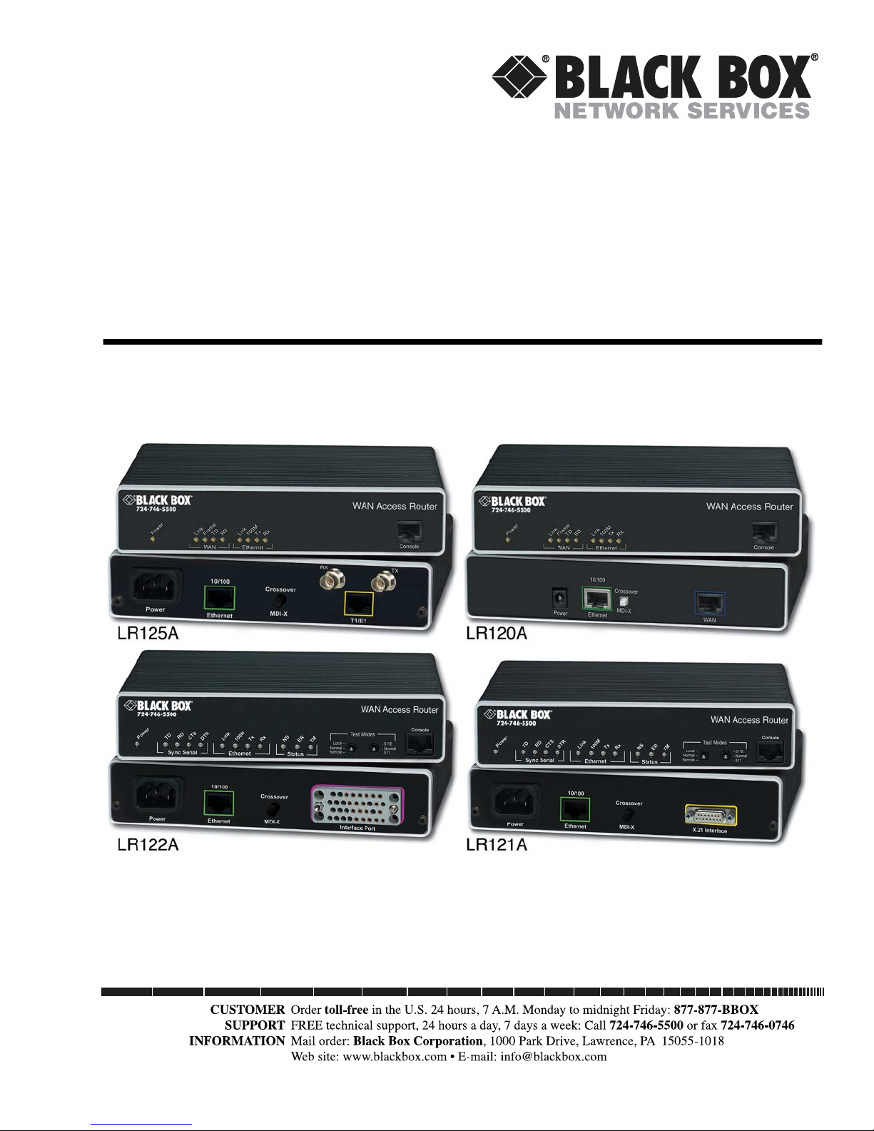
LR120A, LR121A, LR122A, LR125A
WAN Access Routers
Getting Started Guide
Page 2

IC
Compliance Information
and TV
Radio
The WAN Access Router generates and uses radio frequency energy, and if not installed and used properly-that
is, in strict accordance with the manufacturer’s instructions-may cause interference to radio and television
reception. The WAN Access Router have been tested and found to comply with the limits for a Class A computing device in accordance with specifications in Subpart B of Part 15 of FCC rules, which are designed to
provide reasonable protection from such interference in a commercial installation. However, there is no guarantee that interference will not occur in a particular installation. If The WAN Access Router does cause interference to radio or television reception, which can be determined by disconnecting the unit, the user is
encouraged to try to correct the interference by one or more of the following measures: moving the computing
equipment away from the receiver, re-orienting the receiving antenna and/or plugging the receiving equipment
into a different AC outlet (such that the computing equipment and receiver are on different branches).
CE Notice
The CE symbol on your Black Box equipment indicates that it is in compliance with the Electromagnetic
Compatibility (EMC) directive and the Low Voltage Directive (LVD) of the European Union (EU). A Certificate of Compliance is available by contacting Technical Support.
Interference
FCC Part 68 (ACTA) Statement (LR120A only)
This equipment complies with Part 68 of FCC rules and the requirements adopted by ACTA. On the bottom
side of this equipment is a label that contains—among other information—a product identifier in the format
US: AAAEQ##TXXXX . If requested, this number must be provided to the telephone company.
A plug and jack used to connect this equipment to the premises wiring and telephone network must comply
with the applicable FCC Part 68 rules and requirements adopted by the ACTA.
This equipment uses a Universal Service Order Code (USOC) jack: RJ-11C.
If this equipment causes harm to the telephone network, the telephone company will notify you in advance
that temporary discontinuance of service may be required. But if advance notice isn’t practical, the telephone
company will notify the customer as soon as possible. Also, you will be advised of your right to file a complaint
with the FCC if you believe it is necessary.
The telephone company may make changes in its facilities, equipment, operations or procedures that could
affect the operation of the equipment. If this happens the telephone company will provide advance notice in
order for you to make necessary modifications to maintain uninterrupted service.
If trouble is experienced with this equipment, for repair or warranty information, please contact our company.
If the equipment is causing harm to the telephone network, the telephone company may request that you disconnect the equipment until the problem is resolved.
Connection to party line service is subject to state tariffs. Contact the state public utility commission, public
service commission or corporation commission for information.
Industry Canada Notice
Note
This equipment meets the applicable Industry Canada Terminal Equipment Technical Specifications. This is confirmed by the registration number. The abbreviation,
, before the registration number signifies that registration was performed based on
a Declaration of conformity indicating that Industry Canada technical specifications
were met. It does not imply that Industry Canada approved the equipment.
Page 3

Trademarks Used In This Manual
All applied-for and registered trademarks are the property of their respective owners.
Normas Oficiales Mexicanas (NOM)
Electrical Safety Statement
Instrucciones De Seguridad
1. Todas las instrucciones de seguridad y operación deberán ser leídas antes de que el aparato eléctrico sea
operado.
2. Las instrucciones de seguridad y operación deberán ser guardadas para referencia futura.
3. Todas las advertencias en el aparato eléctrico y en sus instrucciones de operación deben ser respetadas.
4. Todas las instrucciones de operación y uso deben ser seguidas.
5. El aparato eléctrico no deberá ser usado cerca del agua—por ejemplo, cerca de la tina de baño, lavabo,
sótano mojado o cerca de una alberca, etc.
6. El aparato eléctrico debe ser usado únicamente con carritos o pedestales que sean recomendados por el
fabricante.
7. El aparato eléctrico debe ser montado a la pared o al techo sólo como sea recomendado por el fabricante.
8. Servicio—El usuario no debe intentar dar servicio al equipo eléctrico más allá a lo descrito en las
instrucciones de operación. Todo otro servicio deberá ser referido a personal de servicio calificado.
9. El aparato eléctrico debe ser situado de tal manera que su posición no interfiera su uso. La colocación del
aparato eléctrico sobre una cama, sofá, alfombra o superficie similar puede bloquea la ventilación, no se
debe colocar en libreros o gabinetes que impidan el flujo de aire por los orificios de ventilación.
10. El equipo eléctrico deber ser situado fuera del alcance de fuentes de calor como radiadores, registros de
calor, estufas u otros aparatos (incluyendo amplificadores) que producen calor.
11. El aparato eléctrico deberá ser connectado a una fuente de poder sólo del tipo descrito en el instructivo
de operación, o como se indique en el aparato.
12. Precaución debe ser tomada de tal manera que la tierra fisica y la polarización del equipo no sea eliminada.
13. Los cables de la fuente de poder deben ser guiados de tal manera que no sean pisados ni pellizcados
por objetos colocados sobre o contra ellos, poniendo particular atención a los contactos y receptáculos
donde salen del aparato.
14. El equipo eléctrico debe ser limpiado únicamente de acuerdo a las recomendaciones del fabricante.
15. En caso de existir, una antena externa deberá ser localizada lejos de las lineas de energia.
Page 4

16. El cable de corriente deberá ser desconectado del cuando el equipo no sea usado por un largo periodo
de tiempo.
17. Cuidado debe ser tomado de tal manera que objectos liquidos no sean derramados sobre la cubierta u
orificios de ventilación.
18. Servicio por personal calificado deberá ser provisto cuando:
— A: El cable de poder o el contacto ha sido dañado; o
— B: Objectos han caído o líquido ha sido derramado dentro del aparato; o
— C: El aparato ha sido expuesto a la lluvia; o
— D: El aparato parece no operar normalmente o muestra un cambio en su desempeño; o
— E: El aparato ha sido tirado o su cubierta ha sido dañada.
Page 5

Summary Table of Contents
1 General Information ......................................................................................................................................12
2 Product Overview...........................................................................................................................................19
3 Initial configuration .......................................................................................................................................22
4 Ethernet LAN Port .........................................................................................................................................34
5 Serial Port Configuration ...............................................................................................................................38
6 WAN Services .................................................................................................................................................45
7 Security ..........................................................................................................................................................62
8 DHCP and DNS configuration ......................................................................................................................76
9 IP Services ......................................................................................................................................................87
10 System Configuration.....................................................................................................................................90
11 SNTP Client Configuration ...........................................................................................................................99
12 System Status................................................................................................................................................102
A Specifications ..............................................................................................................................................106
B Cable recommendations ..............................................................................................................................110
C Black Box physical connectors ....................................................................................................................112
D Command Line Interface (CLI) Operation .................................................................................................117
5
Page 6

Table of Contents
Compliance Information................................................................................................................................. 2
Radio and TV Interference ...............................................................................................................................2
CE Notice .........................................................................................................................................................2
FCC Part 68 (ACTA) Statement (LR120A only) ..............................................................................................2
Industry Canada Notice ....................................................................................................................................2
Summary Table of Contents ............................................................................................................................5
Table of Contents ............................................................................................................................................1
List of Figures ..................................................................................................................................................6
List of Tables ...................................................................................................................................................8
About this guide ..............................................................................................................................................9
Audience.......................................................................................................................................................... 9
Structure.......................................................................................................................................................... 9
Precautions.................................................................................................................................................... 10
Factory default parameters ............................................................................................................................ 10
Typographical conventions used in this document ....................................................................................... 11
General conventions .......................................................................................................................................11
Mouse conventions .........................................................................................................................................11
1 General Information ......................................................................................................................................12
WAN Access High Speed Routers overview...........................................................................................................13
General attributes ...........................................................................................................................................13
Ethernet ..........................................................................................................................................................14
Protocol support .............................................................................................................................................14
PPP support ....................................................................................................................................................14
WAN interfaces ..............................................................................................................................................14
Management ...................................................................................................................................................14
Security ...........................................................................................................................................................15
Front panel status LEDs and console port .......................................................................................................15
Console port .............................................................................................................................................16
Rear panel connectors and switches .................................................................................................................17
Power connector .......................................................................................................................................17
AC universal power supply .................................................................................................................17
48 VDC power supply ........................................................................................................................17
Ethernet port (outlined in green) ..............................................................................................................17
MDI-X .....................................................................................................................................................18
2 Product Overview...........................................................................................................................................19
Introduction..........................................................................................................................................................20
Applications overview............................................................................................................................................21
3 Initial configuration .......................................................................................................................................22
Hardware installation ............................................................................................................................................23
1
Page 7

2
WAN Access Routers Getting Started Guide
Table of Contents
What you will need .........................................................................................................................................23
Interface cable installation ...............................................................................................................................23
Installing an interface cable on the Black Box LR120A’s T1/E1 interface port ..........................................24
Installing an interface cable on the Black Box LR121A’s X.21 interface port .............................................26
Installing an interface cable on the Black Box LR122A’s V.35 interface port .............................................28
Installing the AC power cord ..........................................................................................................................29
Installing the Ethernet cable ............................................................................................................................31
IP address modification ...................................................................................................................................31
Web operation and configuration ...................................................................................................................32
PC configuration .......................................................................................................................................32
Web browser .............................................................................................................................................32
4 Ethernet LAN Port .........................................................................................................................................34
Introduction..........................................................................................................................................................35
LAN connections ............................................................................................................................................35
Ethernet Port ..................................................................................................................................................35
5 Serial Port Configuration ...............................................................................................................................38
WAN serial port configuration ..............................................................................................................................39
Serial interface .................................................................................................................................................39
Variables ...................................................................................................................................................39
Web interface configuration ......................................................................................................................40
T1/E1 interface configuration .........................................................................................................................40
Configuring the WAN Access Routers LR120A for T1 operation .............................................................41
Web configuration ..............................................................................................................................41
Configuring the WAN Access Routers LR120A for E1 operation .............................................................42
Web configuration ..............................................................................................................................42
Configuring the WAN Access Routers LR120A for E1 operation .............................................................43
Web Configuration .............................................................................................................................43
6 WAN Services .................................................................................................................................................45
Introduction..........................................................................................................................................................46
PPP Bridged.......................................................................................................................................................... 46
Remote site configuration ...............................................................................................................................46
Central site configuration ................................................................................................................................47
PPP Routed...........................................................................................................................................................48
Remote site configuration ...............................................................................................................................48
Central site configuration ................................................................................................................................51
LMI Management (Frame Relay links)..................................................................................................................52
LMI configuration ..........................................................................................................................................52
Frame Relay Local Management Interface .................................................................................................52
LMI Configuration Options .....................................................................................................................53
Web Configuration Methods ....................................................................................................................54
Frame Relay bridged..............................................................................................................................................54
Remote site configuration ...............................................................................................................................54
Central site configuration ................................................................................................................................56
Page 8

3
WAN Access Routers Getting Started Guide
Table of Contents
Frame Relay Routed ..............................................................................................................................................57
Remote site configuration ...............................................................................................................................57
Central site configuration ................................................................................................................................60
7 Security ..........................................................................................................................................................62
Introduction..........................................................................................................................................................63
Configuring the router ..........................................................................................................................................63
Configuring the security interfaces.........................................................................................................................65
Configuring security policies ...........................................................................................................................66
Deleting a security Policy ..........................................................................................................................67
Enabling the Firewall.............................................................................................................................................67
Firewall Portfilters .................................................................................................................................................68
Security Triggers....................................................................................................................................................69
Intrusion Detection System (IDS).........................................................................................................................70
Introduction to NAT ............................................................................................................................................73
Enabling NAT ................................................................................................................................................73
Global address pool and reserved map .............................................................................................................73
8 DHCP and DNS configuration ......................................................................................................................76
Introduction..........................................................................................................................................................77
Services and features normally associated with each other ................................................................................77
DHCP Server .................................................................................................................................................78
Parameters for the DHCP Server subnet ...................................................................................................80
IP Addresses to be available on this subnet ................................................................................................81
DNS server option information .................................................................................................................82
Default gateway option information ..........................................................................................................82
Additional option information ..................................................................................................................83
DHCP Relay ..................................................................................................................................................83
Configuration of the DHCP Relay ............................................................................................................83
DNS Relay ......................................................................................................................................................85
Configuring the DNS Relay ......................................................................................................................85
9 IP Services ......................................................................................................................................................87
Introduction..........................................................................................................................................................88
WEB Server...........................................................................................................................................................88
CLI Configuration ..........................................................................................................................................88
Associated Ports for the different System (IP) Services ....................................................................................89
10 System Configuration.....................................................................................................................................90
Introduction..........................................................................................................................................................91
Detailed Description .............................................................................................................................................91
Authentication ................................................................................................................................................91
Alarm ..............................................................................................................................................................92
Remote Access ................................................................................................................................................94
Update ............................................................................................................................................................94
Save ................................................................................................................................................................95
Page 9

4
WAN Access Routers Getting Started Guide
Table of Contents
Backup/Restore ...............................................................................................................................................95
Restart ............................................................................................................................................................96
Website Settings .............................................................................................................................................96
Error Log ........................................................................................................................................................97
SNMP Daemon ..............................................................................................................................................97
System Tools ..................................................................................................................................................98
11 SNTP Client Configuration ...........................................................................................................................99
Introduction........................................................................................................................................................100
Configuring the SNTP client ..............................................................................................................................100
SNTP Client Mode Configuration Parameters .............................................................................................100
SNTP Client General Configuration Parameters ..........................................................................................101
System Clock Setting...........................................................................................................................................101
12 System Status................................................................................................................................................102
System Status.......................................................................................................................................................103
Port Connection Status .................................................................................................................................103
LAN Status ...................................................................................................................................................104
WAN Status .................................................................................................................................................104
Hardware Status ............................................................................................................................................104
Defined Interfaces .........................................................................................................................................104
Status LEDs.........................................................................................................................................................105
A Specifications ..............................................................................................................................................106
General Characteristics........................................................................................................................................ 107
Ethernet ..............................................................................................................................................................107
Sync Serial Interface ............................................................................................................................................107
T1/E1 Interface...................................................................................................................................................107
Protocol Support .................................................................................................................................................107
PPP Support........................................................................................................................................................108
Management .......................................................................................................................................................108
Security ...............................................................................................................................................................108
Compliance Standard Requirements....................................................................................................................109
Australia Specific .....................................................................................................................................109
Dimensions .........................................................................................................................................................109
Power and Power Supply Specifications...............................................................................................................109
AC universal power supply ......................................................................................................................109
48 VDC power supply ............................................................................................................................109
B Cable recommendations ..............................................................................................................................110
Ethernet Cable ....................................................................................................................................................111
Adapter................................................................................................................................................................111
C Black Box physical connectors ....................................................................................................................112
RJ-45 shielded 10/100 Ethernet port...................................................................................................................113
RJ-45 non-shielded RS-232 console port (EIA-561)............................................................................................ 113
Serial port............................................................................................................................................................114
Page 10

5
WAN Access Routers Getting Started Guide
Table of Contents
V.35 (M/34 and DB-25 Connector) .............................................................................................................114
X.21 (DB-15 Connector) ..............................................................................................................................115
E1/T1 (RJ-48C Connector) ..........................................................................................................................116
D Command Line Interface (CLI) Operation .................................................................................................117
Introduction........................................................................................................................................................118
CLI Terminology ................................................................................................................................................118
Local (VT-100 emulation) ............................................................................................................................118
Remote (Telnet) ...........................................................................................................................................118
Using the Console .........................................................................................................................................118
Administering user accounts................................................................................................................................120
Adding new users ..........................................................................................................................................120
Setting user passwords ...................................................................................................................................121
Changing user settings ..................................................................................................................................121
Controlling login access ..........................................................................................................................121
Controlling user access ............................................................................................................................121
Page 11

List of Figures
1 WAN Access Router (LR120A shown) . . . . . . . . . . . . . . . . . . . . . . . . . . . . . . . . . . . . . . . . . . . . . . . . . . . . . . . 15
2 Sync Serial Application . . . . . . . . . . . . . . . . . . . . . . . . . . . . . . . . . . . . . . . . . . . . . . . . . . . . . . . . . . . . . . . . . . . 21
3 T1/E1 Application . . . . . . . . . . . . . . . . . . . . . . . . . . . . . . . . . . . . . . . . . . . . . . . . . . . . . . . . . . . . . . . . . . . . . . 21
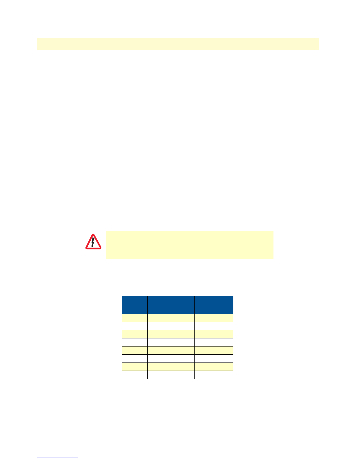
4 Rear View of the LR120A showing location of Ethernet and WAN connectors . . . . . . . . . . . . . . . . . . . . . . . . 24
5 RJ-48C pinout diagram . . . . . . . . . . . . . . . . . . . . . . . . . . . . . . . . . . . . . . . . . . . . . . . . . . . . . . . . . . . . . . . . . . 24
6 Rear view of the LR125A showing location of Ethernet and WAN connectors . . . . . . . . . . . . . . . . . . . . . . . . . 25
7 Rear view of the LR121A showing location of Ethernet and X.21 connectors . . . . . . . . . . . . . . . . . . . . . . . . . . 26
8 Case being opened with a screwdriver . . . . . . . . . . . . . . . . . . . . . . . . . . . . . . . . . . . . . . . . . . . . . . . . . . . . . . . . 26
9 Location of DTE/DCE board . . . . . . . . . . . . . . . . . . . . . . . . . . . . . . . . . . . . . . . . . . . . . . . . . . . . . . . . . . . . . . 27
10 Rear view of the LR122A showing location of Ethernet and V.35 connectors . . . . . . . . . . . . . . . . . . . . . . . . . . 28
11 Connecting the LR122A to a DCE device . . . . . . . . . . . . . . . . . . . . . . . . . . . . . . . . . . . . . . . . . . . . . . . . . . . . 28
12 Power connector location on rear panel (LR120A shown) . . . . . . . . . . . . . . . . . . . . . . . . . . . . . . . . . . . . . . . . 29
13 Black Box front panel LEDs and Console port locations (LR120A shown) . . . . . . . . . . . . . . . . . . . . . . . . . . . . 30
14 LR120A home page . . . . . . . . . . . . . . . . . . . . . . . . . . . . . . . . . . . . . . . . . . . . . . . . . . . . . . . . . . . . . . . . . . . . . 32
15 LR121A home page . . . . . . . . . . . . . . . . . . . . . . . . . . . . . . . . . . . . . . . . . . . . . . . . . . . . . . . . . . . . . . . . . . . . . 33
16 LR122A home page . . . . . . . . . . . . . . . . . . . . . . . . . . . . . . . . . . . . . . . . . . . . . . . . . . . . . . . . . . . . . . . . . . . . . 33
17 Ethernet LAN port IP address configuration . . . . . . . . . . . . . . . . . . . . . . . . . . . . . . . . . . . . . . . . . . . . . . . . . . . 35
18 Basic Ethernet port attributes . . . . . . . . . . . . . . . . . . . . . . . . . . . . . . . . . . . . . . . . . . . . . . . . . . . . . . . . . . . . . . 36
19 Advanced Ethernet port attributes . . . . . . . . . . . . . . . . . . . . . . . . . . . . . . . . . . . . . . . . . . . . . . . . . . . . . . . . . . 36
20 Configurable Ethernet parameters . . . . . . . . . . . . . . . . . . . . . . . . . . . . . . . . . . . . . . . . . . . . . . . . . . . . . . . . . . 37
21 LR121A X.21 serial port configuration parameters . . . . . . . . . . . . . . . . . . . . . . . . . . . . . . . . . . . . . . . . . . . . . . 40
22 LR122A V.35 serial port configuration parameters . . . . . . . . . . . . . . . . . . . . . . . . . . . . . . . . . . . . . . . . . . . . . . 40
23 LR120A T1/E1 WAN port configuration parameters . . . . . . . . . . . . . . . . . . . . . . . . . . . . . . . . . . . . . . . . . . . . 41
24 T1 configuration . . . . . . . . . . . . . . . . . . . . . . . . . . . . . . . . . . . . . . . . . . . . . . . . . . . . . . . . . . . . . . . . . . . . . . . 41
25 E1 port configuration . . . . . . . . . . . . . . . . . . . . . . . . . . . . . . . . . . . . . . . . . . . . . . . . . . . . . . . . . . . . . . . . . . . . 42
26 E1 port configuration . . . . . . . . . . . . . . . . . . . . . . . . . . . . . . . . . . . . . . . . . . . . . . . . . . . . . . . . . . . . . . . . . . . . 43
27 PPP Bridged Application . . . . . . . . . . . . . . . . . . . . . . . . . . . . . . . . . . . . . . . . . . . . . . . . . . . . . . . . . . . . . . . . . 46
28 WAN services’ options . . . . . . . . . . . . . . . . . . . . . . . . . . . . . . . . . . . . . . . . . . . . . . . . . . . . . . . . . . . . . . . . . . . 46
29 Configuring PPP bridged WAN service . . . . . . . . . . . . . . . . . . . . . . . . . . . . . . . . . . . . . . . . . . . . . . . . . . . . . . 47
30 PPP Routed Application . . . . . . . . . . . . . . . . . . . . . . . . . . . . . . . . . . . . . . . . . . . . . . . . . . . . . . . . . . . . . . . . . . 48
31 PPP Routed Configuration menu . . . . . . . . . . . . . . . . . . . . . . . . . . . . . . . . . . . . . . . . . . . . . . . . . . . . . . . . . . . 49
32 Edit IP address of WAN port . . . . . . . . . . . . . . . . . . . . . . . . . . . . . . . . . . . . . . . . . . . . . . . . . . . . . . . . . . . . . . 49
33 Configuring the gateway . . . . . . . . . . . . . . . . . . . . . . . . . . . . . . . . . . . . . . . . . . . . . . . . . . . . . . . . . . . . . . . . . . 50
34 PPP link status . . . . . . . . . . . . . . . . . . . . . . . . . . . . . . . . . . . . . . . . . . . . . . . . . . . . . . . . . . . . . . . . . . . . . . . . . 51
35 LMI Configuration webpage . . . . . . . . . . . . . . . . . . . . . . . . . . . . . . . . . . . . . . . . . . . . . . . . . . . . . . . . . . . . . . . 54
36 Frame Relay bridged application . . . . . . . . . . . . . . . . . . . . . . . . . . . . . . . . . . . . . . . . . . . . . . . . . . . . . . . . . . . . 54
37 Frame Relay bridged creation . . . . . . . . . . . . . . . . . . . . . . . . . . . . . . . . . . . . . . . . . . . . . . . . . . . . . . . . . . . . . . 55
38 Frame Relay Channel configuration . . . . . . . . . . . . . . . . . . . . . . . . . . . . . . . . . . . . . . . . . . . . . . . . . . . . . . . . . 56
39 Frame Relay routed application . . . . . . . . . . . . . . . . . . . . . . . . . . . . . . . . . . . . . . . . . . . . . . . . . . . . . . . . . . . . 57
40 Frame Relay routed configuration . . . . . . . . . . . . . . . . . . . . . . . . . . . . . . . . . . . . . . . . . . . . . . . . . . . . . . . . . . . 58
41 Frame Relay Channel - Routed configuration . . . . . . . . . . . . . . . . . . . . . . . . . . . . . . . . . . . . . . . . . . . . . . . . . . 59
42 IP route for Frame Relay routed application . . . . . . . . . . . . . . . . . . . . . . . . . . . . . . . . . . . . . . . . . . . . . . . . . . . 60
43 PPP routed WAN service for Security Firewall example . . . . . . . . . . . . . . . . . . . . . . . . . . . . . . . . . . . . . . . . . . 64
44 IP address of PPP routed WAN service . . . . . . . . . . . . . . . . . . . . . . . . . . . . . . . . . . . . . . . . . . . . . . . . . . . . . . . 64
45 Valid gateway route . . . . . . . . . . . . . . . . . . . . . . . . . . . . . . . . . . . . . . . . . . . . . . . . . . . . . . . . . . . . . . . . . . . . . 65
46 Security configuration home page . . . . . . . . . . . . . . . . . . . . . . . . . . . . . . . . . . . . . . . . . . . . . . . . . . . . . . . . . . . 65
47 Define ‘ip1’ interface as Internal . . . . . . . . . . . . . . . . . . . . . . . . . . . . . . . . . . . . . . . . . . . . . . . . . . . . . . . . . . . . 66
6
Page 12

7
WAN Access Routers Getting Started Guide
48 Define ‘ppp-0’ interface as External . . . . . . . . . . . . . . . . . . . . . . . . . . . . . . . . . . . . . . . . . . . . . . . . . . . . . . . . . 66
49 Security Policy Configuration hyperlink . . . . . . . . . . . . . . . . . . . . . . . . . . . . . . . . . . . . . . . . . . . . . . . . . . . . . . 67
50 New Policy link to configuration webpage . . . . . . . . . . . . . . . . . . . . . . . . . . . . . . . . . . . . . . . . . . . . . . . . . . . . 67
51 Deleting a Security Policy . . . . . . . . . . . . . . . . . . . . . . . . . . . . . . . . . . . . . . . . . . . . . . . . . . . . . . . . . . . . . . . . . 67
52 Defining ICMP port filter for ping . . . . . . . . . . . . . . . . . . . . . . . . . . . . . . . . . . . . . . . . . . . . . . . . . . . . . . . . . . 69
53 Configuring TCP port filter for FTP . . . . . . . . . . . . . . . . . . . . . . . . . . . . . . . . . . . . . . . . . . . . . . . . . . . . . . . . 69
54 Adding trigger for FTP data transfer . . . . . . . . . . . . . . . . . . . . . . . . . . . . . . . . . . . . . . . . . . . . . . . . . . . . . . . . . 70
55 NAT Global Address Pool configuration . . . . . . . . . . . . . . . . . . . . . . . . . . . . . . . . . . . . . . . . . . . . . . . . . . . . . 74
56 NAT Reserved mapping configuration . . . . . . . . . . . . . . . . . . . . . . . . . . . . . . . . . . . . . . . . . . . . . . . . . . . . . . . 75
57 DHCP Server web page . . . . . . . . . . . . . . . . . . . . . . . . . . . . . . . . . . . . . . . . . . . . . . . . . . . . . . . . . . . . . . . . . . 79
58 DHCP server configuration web page . . . . . . . . . . . . . . . . . . . . . . . . . . . . . . . . . . . . . . . . . . . . . . . . . . . . . . . . 80
59 DHCP Server subnet parameters . . . . . . . . . . . . . . . . . . . . . . . . . . . . . . . . . . . . . . . . . . . . . . . . . . . . . . . . . . . 80
60 DHCP IP address pool . . . . . . . . . . . . . . . . . . . . . . . . . . . . . . . . . . . . . . . . . . . . . . . . . . . . . . . . . . . . . . . . . . . 81
61 Example based on default range of IP address pool . . . . . . . . . . . . . . . . . . . . . . . . . . . . . . . . . . . . . . . . . . . . . . 82
62 Configuration of the DNS server IP addresses . . . . . . . . . . . . . . . . . . . . . . . . . . . . . . . . . . . . . . . . . . . . . . . . . 82
63 DHCP server optional information example . . . . . . . . . . . . . . . . . . . . . . . . . . . . . . . . . . . . . . . . . . . . . . . . . . . 83
64 DHCP Relay webpage . . . . . . . . . . . . . . . . . . . . . . . . . . . . . . . . . . . . . . . . . . . . . . . . . . . . . . . . . . . . . . . . . . . 84
65 DHCP Relay server list . . . . . . . . . . . . . . . . . . . . . . . . . . . . . . . . . . . . . . . . . . . . . . . . . . . . . . . . . . . . . . . . . . . 84
66 Hyperlink path to the DNS Relay webpage . . . . . . . . . . . . . . . . . . . . . . . . . . . . . . . . . . . . . . . . . . . . . . . . . . . 85
67 DNS Relay configuration webpage . . . . . . . . . . . . . . . . . . . . . . . . . . . . . . . . . . . . . . . . . . . . . . . . . . . . . . . . . . 86
68 DNS Relay - configuration completed . . . . . . . . . . . . . . . . . . . . . . . . . . . . . . . . . . . . . . . . . . . . . . . . . . . . . . . 86
69 System Services configuration web page . . . . . . . . . . . . . . . . . . . . . . . . . . . . . . . . . . . . . . . . . . . . . . . . . . . . . . 88
70 Authentication web page showing default superuser . . . . . . . . . . . . . . . . . . . . . . . . . . . . . . . . . . . . . . . . . . . . . 91
71 Creating new user . . . . . . . . . . . . . . . . . . . . . . . . . . . . . . . . . . . . . . . . . . . . . . . . . . . . . . . . . . . . . . . . . . . . . . . 92
72 Alarm Management web-page . . . . . . . . . . . . . . . . . . . . . . . . . . . . . . . . . . . . . . . . . . . . . . . . . . . . . . . . . . . . . . 92
73 Alarm & Alarm Error Log configuration . . . . . . . . . . . . . . . . . . . . . . . . . . . . . . . . . . . . . . . . . . . . . . . . . . . . . . 93
74 Remote Access (Telnet) access limit . . . . . . . . . . . . . . . . . . . . . . . . . . . . . . . . . . . . . . . . . . . . . . . . . . . . . . . . . 94
75 Updating software . . . . . . . . . . . . . . . . . . . . . . . . . . . . . . . . . . . . . . . . . . . . . . . . . . . . . . . . . . . . . . . . . . . . . . 94
76 Save configuration changes in non-volatile memory . . . . . . . . . . . . . . . . . . . . . . . . . . . . . . . . . . . . . . . . . . . . . 95
77 Saving or reloading previously saved configuration files . . . . . . . . . . . . . . . . . . . . . . . . . . . . . . . . . . . . . . . . . . 95
78 Restoring to factory defaults . . . . . . . . . . . . . . . . . . . . . . . . . . . . . . . . . . . . . . . . . . . . . . . . . . . . . . . . . . . . . . . 96
79 Webpage refresh rates . . . . . . . . . . . . . . . . . . . . . . . . . . . . . . . . . . . . . . . . . . . . . . . . . . . . . . . . . . . . . . . . . . . . 96
80 Error Log and Syslog Settings . . . . . . . . . . . . . . . . . . . . . . . . . . . . . . . . . . . . . . . . . . . . . . . . . . . . . . . . . . . . . . 97
81 SNMP Daemon configuration . . . . . . . . . . . . . . . . . . . . . . . . . . . . . . . . . . . . . . . . . . . . . . . . . . . . . . . . . . . . . 98
82 Ping and Traceroute utilities . . . . . . . . . . . . . . . . . . . . . . . . . . . . . . . . . . . . . . . . . . . . . . . . . . . . . . . . . . . . . . . 98
83 SNTP synchronization and server IP address configuration . . . . . . . . . . . . . . . . . . . . . . . . . . . . . . . . . . . . . . 100
84 Timezone and Polling packet configuration . . . . . . . . . . . . . . . . . . . . . . . . . . . . . . . . . . . . . . . . . . . . . . . . . . 101
85 Configuration of the internal system calendar clock . . . . . . . . . . . . . . . . . . . . . . . . . . . . . . . . . . . . . . . . . . . . 101
86 System Status: subsystems’ summary . . . . . . . . . . . . . . . . . . . . . . . . . . . . . . . . . . . . . . . . . . . . . . . . . . . . . . . . 103
87 X.21 DB-15 connector . . . . . . . . . . . . . . . . . . . . . . . . . . . . . . . . . . . . . . . . . . . . . . . . . . . . . . . . . . . . . . . . . . 115
88 T1/E1 RJ-48C connector . . . . . . . . . . . . . . . . . . . . . . . . . . . . . . . . . . . . . . . . . . . . . . . . . . . . . . . . . . . . . . . . 116
Page 13

List of Tables
1 General conventions . . . . . . . . . . . . . . . . . . . . . . . . . . . . . . . . . . . . . . . . . . . . . . . . . . . . . . . . . . . . . . . . . . . . . 11
2 Mouse conventions . . . . . . . . . . . . . . . . . . . . . . . . . . . . . . . . . . . . . . . . . . . . . . . . . . . . . . . . . . . . . . . . . . . . . . 11
3 Status LED descriptions . . . . . . . . . . . . . . . . . . . . . . . . . . . . . . . . . . . . . . . . . . . . . . . . . . . . . . . . . . . . . . . . . . 16
4 LMI Implementation on the Black Box . . . . . . . . . . . . . . . . . . . . . . . . . . . . . . . . . . . . . . . . . . . . . . . . . . . . . . 52
5 Features and services matrix . . . . . . . . . . . . . . . . . . . . . . . . . . . . . . . . . . . . . . . . . . . . . . . . . . . . . . . . . . . . . . . 78
6 Standard port numbers for the System Services . . . . . . . . . . . . . . . . . . . . . . . . . . . . . . . . . . . . . . . . . . . . . . . . . 89
7 Status LED descriptions . . . . . . . . . . . . . . . . . . . . . . . . . . . . . . . . . . . . . . . . . . . . . . . . . . . . . . . . . . . . . . . . . 105
8 Ethernet Port (MDI-X switch in out position) . . . . . . . . . . . . . . . . . . . . . . . . . . . . . . . . . . . . . . . . . . . . . . . . 113
9 RS-232 Control Port . . . . . . . . . . . . . . . . . . . . . . . . . . . . . . . . . . . . . . . . . . . . . . . . . . . . . . . . . . . . . . . . . . . 113
10 V.35 pinout for M/34 & DB-25 connectors . . . . . . . . . . . . . . . . . . . . . . . . . . . . . . . . . . . . . . . . . . . . . . . . . 114
11 X.21 Interface (LR121A) . . . . . . . . . . . . . . . . . . . . . . . . . . . . . . . . . . . . . . . . . . . . . . . . . . . . . . . . . . . . . . . . 115
12 T1/E1 Port . . . . . . . . . . . . . . . . . . . . . . . . . . . . . . . . . . . . . . . . . . . . . . . . . . . . . . . . . . . . . . . . . . . . . . . . . . . 116
8
Page 14

About this guide
This guide describes installing and configuring Black Box WAN Access Routers High Speed Routers. The
instructions in this guide are based on the following assumptions:
• The router may connect to a serial DTE device or T1/E1 line
• There is a LAN connected to the Ethernet port of the router
Audience
This guide is intended for the following users:
• Operators
• Installers
• Maintenance technicians
Structure
This guide contains the following chapters and appendices:
• Chapter 1 provides information about router features and capabilities
• Chapter 2 contains an overview describing router operation
• Chapter 3 provides quick start installation procedures
• Chapter 4 describes configuring the Ethernet WAN port
• Chapter 5 describes configuring the serial port
• Chapter 6 describes configuring WAN services
• Chapter 7 describes configuring security for the router
• Chapter 8 describes configuring DHCP and DNS
• Chapter 9 describes configuring IP services
• Chapter 10 describes configuring system settings
• Chapter 11 describes configuring the SNTP client
• Chapter 12 describes status LEDs
• Appendix A contains specifications for the routers
• Appendix B provides cable recommendations
• Appendix C describes the router’s ports
• Appendix D describes how to use the command line interface (CLI)
For best results, read the contents of this guide before you install the router.
9
Page 15

10
WAN Access Routers Getting Started Guide
Precautions
Notes and cautions, which have the following meanings, are used throughout this guide to help you become
aware of potential Router problems. Warnings relate to personal injury issues, and Cautions refer to potential
property damage.
Note
WARNING
WARNING
CAUTION
CAUTION
Calls attention to important information.
The shock hazard symbol and WARNING heading indicate a potential electric
shock hazard. Strictly follow the warning instructions to avoid injury caused
by electric shock.
The alert symbol and WARNING heading indicate a potential safety hazard.
Strictly follow the warning instructions to avoid personal injury.
The shock hazard symbol and CAUTION heading indicate a
potential electric shock hazard. Strictly follow the instructions to
avoid property damage caused by electric shock.
The alert symbol and CAUTION heading indicate a potential
hazard. Strictly follow the instructions to avoid property damage.
Factory default parameters
WAN Access High Speed Routers have the following factory default parameters.
• Ethernet IP address: 192.168.200.10/24
• WAN Connection: PPP Bridged
• Ethernet and serial connections
• MDI (LAN connector)
• LR121A (X.21)—DB-15 port (DTE)
• LR122A (V.35)—DB-25 port (DCE, DTE when using special V.35 cable)
• LR120A—T1 configuration. RJ-48C (100-ohm) interface
• LR125A—E1 configuration. RJ-48C (120-ohm) and dual-BNC interface (75-ohm)
Page 16

11
WAN Access Routers Getting Started Guide
Typographical conventions used in this document
This section describes the typographical conventions and terms used in this guide.
General conventions
The procedures described in this manual use the following text conventions:
Table 1. General conventions
Convention Meaning
Futura bold type
Italicized Futura type
Futura type Indicates the names of fields or windows.
Garamond bold type Indicates the names of command buttons that execute an action.
< > Angle brackets indicate function and keyboard keys, such as <SHIFT>,
Are you ready? All system messages and prompts appear in the Courier font as the
% dir *.*
Indicates the names of menu bar options.
Indicates the names of options on pull-down menus.
<CTRL>, <C>, and so on.
system would display them.
Bold Courier font indicates where the operator must type a response or
command
Mouse conventions
The following conventions are used when describing mouse actions:
Table 2. Mouse conventions
Convention Meaning
Left mouse button
Right mouse button This button refers the secondary or rightmost mouse button (unless you have
Point This word means to move the mouse in such a way that the tip of the pointing
Click Means to quickly press and release the left or right mouse button (as instructed in
Double-click Means to press and release the same mouse button two times quickly
Drag This word means to point the arrow and then hold down the left or right mouse but-
This button refers to the primary or leftmost mouse button (unless you have
changed the default configuration).
changed the default configuration).
arrow on the screen ends up resting at the desired location.
the procedure). Make sure you do not move the mouse pointer while clicking a
mouse button.
ton (as instructed in the procedure) as you move the mouse to a new location.
When you have moved the mouse pointer to the desired location, you can release
the mouse button.
Page 17

Chapter 1
Chapter contents
WAN Access High Speed Routers overview...........................................................................................................13
General attributes ...........................................................................................................................................13
Ethernet ..........................................................................................................................................................14
Protocol support .............................................................................................................................................14
PPP support ....................................................................................................................................................14
WAN interfaces ..............................................................................................................................................14
Management ...................................................................................................................................................14
Security ...........................................................................................................................................................15
Front panel status LEDs and console port .......................................................................................................15
Console port .............................................................................................................................................16
Rear panel connectors and switches .................................................................................................................17
Power connector .......................................................................................................................................17
AC universal power supply.................................................................................................................. 17
48 VDC power supply ........................................................................................................................ 17
Ethernet port (outlined in green) ..............................................................................................................17
MDI-X .....................................................................................................................................................18
General Information
12
Page 18

13
WAN Access Routers Getting Started Guide
1 • General Information
WAN Access High Speed Routers overview
The WAN Access Routers of gateway routers/bridges combine full set of high-speed IP routing features and
WAN access via PPP/IP/FR protocols. All WAN Access Routers come with an auto-sensing full-duplex
10/100Base-T Ethernet port, MDI-X cross-over switch, console port, and internal or external power supply.
There are three versions in the WAN Access Routers corresponding to a choice of WAN interface:
• The LR120A is equipped with an integrated T1/E1 CSU/DSU for connection to full and fractional
T1/E1 services.
• The LR121A is equipped with DTE/DCE user configurable X.21 interface.
• The LR122A equipped with a V.35 interface presented on a female DB-25 connector and a cable to con-
nect to an M/32-F.
The WAN Access Routers provide selectable bridging or routing functionality along with advanced IP features
such as NAT/NAPT, Firewall, and DHCP. A complete set of configurable PPP/IP/FR WAN protocols allow a
wide range of choices when connecting branches via common WAN services. The WAN Access Routers boast
easy installation offering Console/VT-100, Telnet, HTTP, and SNMP management options.
The following sections describe WAN Access Router features and capabilities:
• General attributes, see section “General attributes”
• Ethernet, see section “Ethernet” on page 14
• Protocol support, see section “Protocol support” on page 14
• PPP support, see section “PPP support” on page 14
• Management, see section “Management” on page 14
• WAN interface, see section “WAN interfaces” on page 14
• Security, see section “Security” on page 15
• Front panel status LEDs, see section “Front panel status LEDs and console port” on page 15
General attributes
• Compact, low cost router/bridge
• 10/100 Ethernet
• Comprehensive hardware diagnostics. Easy maintenance and effortless installation.
• Plug-and-Play operation for fast and seamless turn-up with pre-configured WAN and LAN options.
• Built-in web configuration.
• Setup allows for standard IP address and unique method for entering an IP address and mask without
requiring a console connection. Default IP address of 192.168.1.1/24.
• Simple software upgrades obtained via FTP.
• Front panel LEDs indicate Power, WAN, and Ethernet LAN speed and status.
• Convenient and standard RJ connectors for Ethernet, Line, and Console.
• Standard one-year warranty.
WAN Access High Speed Routers overview
Page 19

14
WAN Access Routers Getting Started Guide
1 • General Information
Ethernet
• Auto-sensing full-duplex 10Base-T/100Base-TX Ethernet.
• Standard RJ-45 connector
• Built-in MDI-X cross-over switch.
• IEEE 802.1d transparent learning bridge.
• 2 IP address/subnets on Ethernet interface.
Protocol support
• Complete internetworking with IP (RFC 741), TCP (RFC 793), UDP (RFC 768), ICMP (RFC 950),
ARP (RFC 826).
• IP router with RIP (RFC 1058), RIPv2 (RFC 2453).
• Support for RIPv1, v2 and static routes.
• Built-in ping and traceroute facilities.
• Integrated DHCP server (RFC 2131).
• DHCP relay agent (RFC 2132/RFC 1542) with 8 individual address pools.
• DNS relay with primary and secondary name server selection.
• NAT (RFC 3022) with network address port translation (NAPT), MultiNat with 1:1, Many:1,
Many:Many mapping, Port/IP redirection and mapping.
• IGMPv2 Proxy support (RFC 2236).
• Frame Relay with Annex A/DLMI, RFC 1490 and FRF.12 Fragmentation.
PPP support
• Point-to-point protocol over HDLC
• PPPoE (RFC 2516) Client for autonomous network connection. Eliminates the requirement of installing
client software on a local PC and allows sharing of the connection across a LAN.
• User configurable PPP PAP (RFC 1661) or CHAP (RFC 1994) authentication.
WAN interfaces
• T1/E1, V.35 or X.21 interfaces
• Available with female RJ-48C, dual BNC, DB-25, and DB-15 connectors
• User configurable DTE/DCE for X.21
Management
• User selectable HDLC or Frame Relay WAN datalink connection.
• Web-Based configuration via embedded web server
• CLI menu for configuration, management, and diagnostics.
• Local/Remote CLI (VT-100 or Telnet).
WAN Access High Speed Routers overview
Page 20
15
WAN Access Routers Getting Started Guide
1 • General Information
• SNMPv1 (RFC 1157) MIB II (RFC 1213)
• Logging via SYSLOG, and VT-100 console.
• Console port set at 9600 bps, 8 data bits, no parity, 1 stop bit, and no flow control.
Security
• Packet filtering firewall for controlled access to and from LAN/WAN. Support for 255 rules in 32 filter sets.
16 individual connection profiles.
• DoS Detection/protection. Intrusion detection, Logging of session, blocking and intrusion events and Real-
Time alerts. Logging or SMTP on event.
• Password protected system management with a username/password for console and virtual terminal. Sepa-
rate user selectable passwords for SNMP RO/RW strings.
• Access list determining up to 5 hosts/networks which are allowed to access management system
SNMP/HTTP/TELNET.
• Logging or SMTP on events: POST, POST errors, PPP/DHCP, IP.
Front panel status LEDs and console port
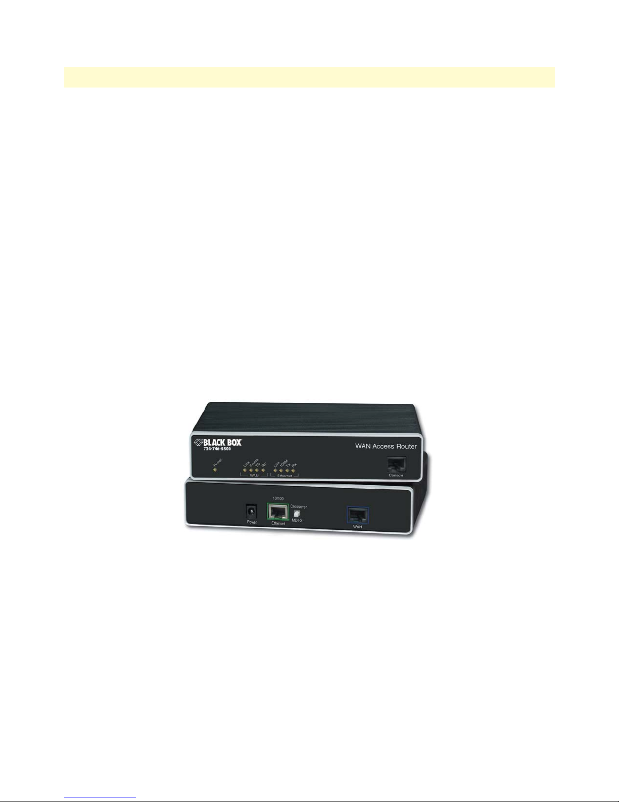
The WAN Access Routers have all status LEDs and console port on the front panel of the unit, and all other
electrical connections are located on the rear panel.
Figure 1. WAN Access Router (LR120A shown)
WAN Access High Speed Routers overview
Page 21

WAN Access Routers Getting Started Guide 1 • General Information
The status LEDs from left to right are (see table 3 for LED descriptions):
• Power
• Sync Serial TD, RD, CTS, and DTR
• Ethernet Link, 100M, Tx, and Rx
Table 3. Status LED descriptions
Power Green ON indicates that power is applied. Off indicates that no power
is applied.
T1/E1 Link Green Solid green: connected
Off: disconnected
LOS Red On: indicates a T1/E1 loss-of-frame condition. It also indicates
that no T1/E1 signal is detected.
TD Green Green: indicates a binary ‘0’ condition
off: indicates a binary ‘1’or idle condition
RD Green Green: indicates a binary ‘0’condition
off: indicates a binary ‘1’ or idle condition
Sync Serial TD Green Green: indicates a binary ‘0’ condition
off: indicates a binary ‘1’or idle condition
RD Green Green: indicates a binary ‘0’condition
off: indicates a binary ‘1’ or idle condition
CTS Green ON: indicates the CTS signal from the router is active, binary
‘1’
off: indicates CTS is binary ‘0’
DTR Green ON: indicates the DTR signal from the DTE device attached to
the serial port is active, binary ‘1’
Ethernet Link Green ON: indicates an active 10/100 Base-T connection
100M Green ON: connected to a 100BaseT LAN
Off: connected to a 10BaseT LAN
Tx Green Flashing: when transmitting data from the router to the Ethernet
Rx Green Flashing: when transmitting data from the Ethernet to the router.
Console port
Located on the front panel, the unshielded RJ-45 RS-232 console DCE port (EIA-561) with the pin-out listed
in the following table
Pin No. Signal Direction Signal Name Pin No. Signal Direction Signal Name
1 Out DSR 5 Out RD
2 Out CD 6 In TD
3 In DTR 7 Out CTS
4 — Signal Ground 8 In RTS
WAN Access High Speed Routers overview 16
:
Page 22
WAN Access Routers Getting Started Guide 1 • General Information
Rear panel connectors and switches
On the rear panel from left to right are the following:
• Power input connector
• Ethernet connector
• MDI-X switch
• WAN port (V.35, X.21, T1/E1)
Power connector
AC universal power supply.
The WAN Access Router offers internal or external AC power supply options.
• The internal power supply connects to an AC source via an IEC-320 connector (100–240 VAC, 200 mA,
50/60 Hz)
• The external power supply connects to an external source providing +5 VDC via a barrel-type connector
48 VDC power supply.
• The DC power supply connects to a DC source via a terminal block
• Rated voltage and current: 36–60 VDC, 400 mA
Connect the equipment to a 36–60 VDC source that is electrically isolated from the AC source. The 36–60 VDC source is to
CAUTION
be reliably connected to earth.
Ethernet port (outlined in green)
Shielded RJ-45 10Base-T/100Base-TX Ethernet port using pins 1, 2, 3, and 6. See MDI-X switch for hub or transceiver configuration.The following table defines conditions that occur when the MDI-X switch is in the out position.
Pin No.
1 Output TX+
2 Output TX3 Input RX+
4 — —
5 — —
6 Input RX7 — —
8 — —
Signal
Direction
Signal
Name
WAN Access High Speed Routers overview 17
Page 23

WAN Access Routers Getting Started Guide 1 • General Information
MDI-X
The MDI-X push switch operates as follows:
• When in the default “out” position, the Ethernet circuitry takes on a straight-through MDI configuration
and functions as a transceiver. It will connect directly to a hub.
• When in the “in” position, the Ethernet circuitry is configured in cross-over MDI-X mode so that a
straight-through cable can connect The WAN Access Router’s Ethernet port directly to a PC’s NIC card.
WAN Access High Speed Routers overview 18
Page 24

Chapter 2 Product Overview
Chapter contents
Introduction..........................................................................................................................................................20
Applications overview............................................................................................................................................21
19
Page 25

WAN Access Routers Getting Started Guide 2 • Product Overview
Introduction
The WAN Access Router operates as a bridge or a router and has two ports for communication:
• The Ethernet port—Connects to the LAN side of the connection
• The Serial port—Connects to local DTE devices (LR121A and LR122A)
• The T1/E1 port—Connects directly to T1/E1 lines (LR120A)
the router provides all layer 2 and layer 3 protocols required for end-to-end-link communication.
When configuring the WAN Access Router, questions must be answered so the WAN Access Router functions
as desired. For example, when a router or bridge module needs to be activated, some questions would be:
• Is a default gateway required?
• Which encapsulation technique is best for this application: Frame Relay, PPP, or another?
These decisions can be made and implemented more easily if the WAN Access Router’s fundamental architecture
is understood. Also, while configuring The WAN Access Router via a browser using the built-in HTTP server is
very intuitive, an understanding of the architecture is essential when using the command-line interface (CLI)
commands.
The fundamental building blocks comprise a router or bridge, interfaces, and transports. the router and bridge
each have interfaces. A transport provides the path between an interface and an external connection. For example, the Ethernet transport attaches to an Internet Protocol (IP) interface. A transport consists of layer 2 and
everything below it. Creating a transport and attaching it to a bridge or router’s interface enables data to be
bridged or routed. The supported transports are PPPoE, Frame Relay, PPP, and Ethernet.
Configuring an interface and transport for the router or bridge requires naming the interface and transport before
attaching them. When using the built-in HTTP server web browser, this is done automatically. But when configuring The WAN Access Router via CLI commands through the RS-232 control port, it must be done manually.
Introduction 20
Page 26

WAN Access Routers Getting Started Guide 2 • Product Overview
Applications overview
Black Box’s WAN Access Routers deliver all the advanced features for secure, reliable, and high speed Internet
data connections. They combine ease-of-use with powerful data routing to make shared Internet connectivity
simple and easy.
With NAT support, the WAN Access Routers offer convenient and economical operation by using a single IP
address while the integrated DHCP server automates IP address assignment for connected LAN computers. Security is standard with built-in firewall and violation alerting features that protect the network from wouldbe intruders.
Figure 2. Sync Serial Application
Figure 3. T1/E1 Application
Applications overview 21
Page 27

Chapter 3 Initial configuration
Chapter contents
Hardware installation ............................................................................................................................................23
What you will need .........................................................................................................................................23
Interface cable installation ...............................................................................................................................23
Installing an interface cable on the Black Box LR120A’s T1/E1 interface port ..........................................24
Installing an interface cable on the Black Box LR121A’s X.21 interface port .............................................26
Installing an interface cable on the Black Box LR122A’s V.35 interface port .............................................28
Installing the AC power cord ..........................................................................................................................29
Installing the Ethernet cable ............................................................................................................................31
IP address modification ...................................................................................................................................31
Web operation and configuration ...................................................................................................................32
PC configuration .......................................................................................................................................32
Web browser .............................................................................................................................................32
22
Page 28

WAN Access Routers Getting Started Guide 3 • Initial configuration
Hardware installation
If you are already familiar with WAN Access Router installation and configuration, this chapter will enable you
to finish the job quickly. Installation consists of the following:
• Preparing for the installation (see section “What you will need”)
• Installing the T1/E1 WAN, X.21, or V.35 interface cable (see section “Interface cable installation”)
• Hooking up network cables, verifying that the unit will power up, and running a HyperTerminal session
(see section “Installing the Ethernet cable” on page 31)
• Changing the IP address from the factory default setting (see section “IP address modification” on page 31)
• Launching a web browser in preparation for configuring the modem (see “Web operation and configura-
tion” on page 32)
What you will need
• WAN Access Routers High Speed Router
• Ethernet cable with RJ45 plugs on each end (included with router)
• DB9-RJ45 adapter (included with router)
• RJ45/RJ45 straight-through cable for connecting to control port (included with router)
• PC computer with HyperTerminal or equivalent VT-100 emulation program, or an ASCII terminal (also
called a dumb terminal) capable of emulating a VT-100.
Interface cable installation
An WAN Access Router comes with a T1/E1 WAN, V.35, or X.21 interface. Refer to the appropriate section to
install an interface cable on your WAN Access Router:
• LR120A Router (see “Installing an interface cable on the Black Box LR120A’s T1/E1 interface port” on
page 24)
• LR121A Router (see “Installing an interface cable on the Black Box LR121A’s X.21 interface port” on
page 26)
• LR122A Router (see “Installing an interface cable on the Black Box LR122A’s V.35 interface port” on
page 28)
Hardware installation 23
Page 29
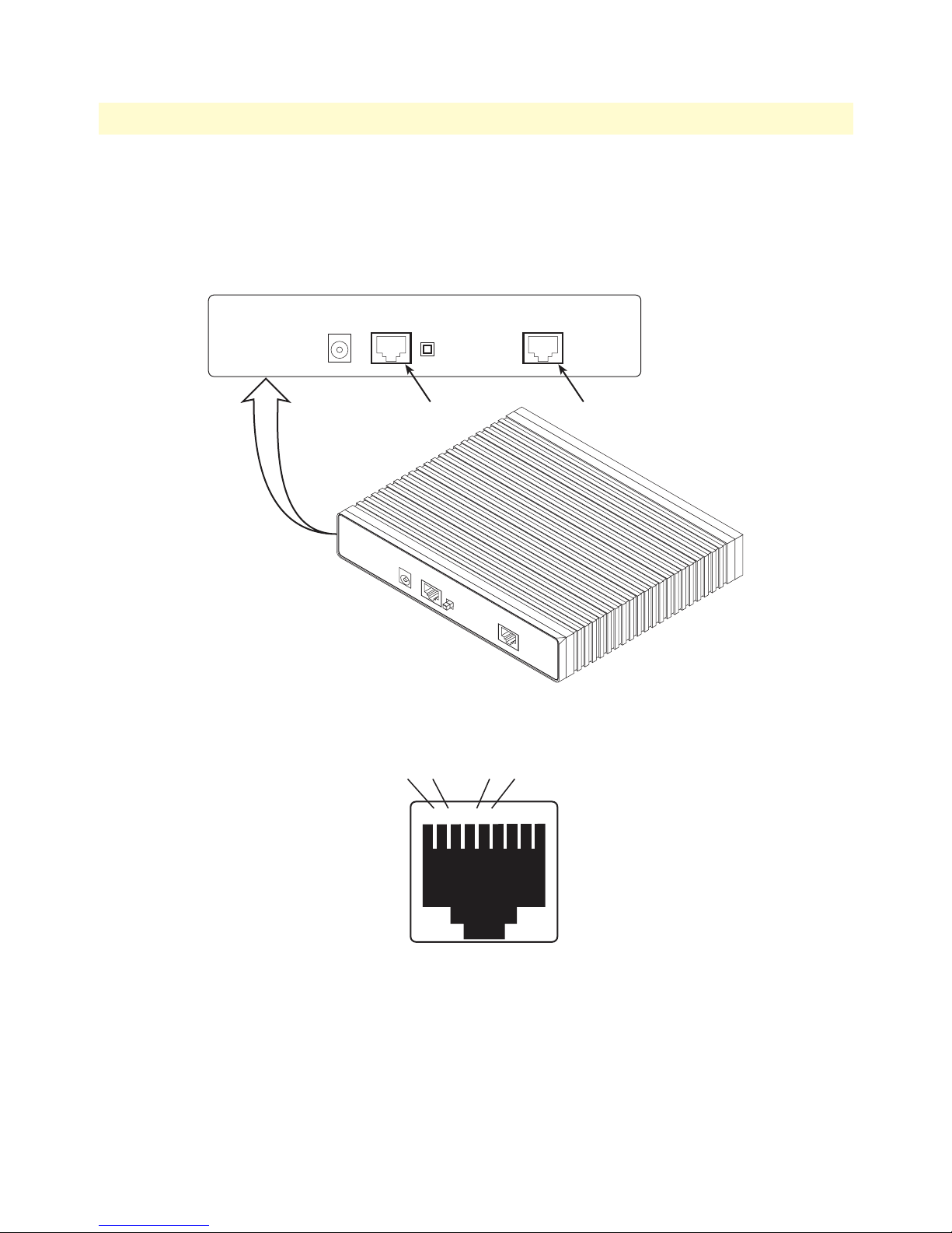
WAN Access Routers Getting Started Guide 3 • Initial configuration
Installing an interface cable on the Black Box LR120A’s T1/E1 interface port
The Black Box Models LR120A and LR125A come with a selectable T1/E1 WAN interface (see figure 4).
Located on the back of the Black Box, the T1 and E1 interfaces are presented on an RJ-48C connector with
selectable line impedances of 100-ohms for T1 and 120-ohms for E1 lines (see figure 5). The LR125A also
comes with dual BNC for alternate connection to unbalanced 75-ohm E1 lines (see figure 6 on page 25).
10/100
Crossover
Power
MDI-X
Ethernet WAN
Ethernet connector
(RJ-45)
10/100
Power
Crossover
10/100
Ethernet
MDI-X
WAN
WAN connector
(RJ-48C)
Figure 4. Rear View of the LR120A showing location of Ethernet and WAN connectors
RX RX TX TX
Hardware installation 24
12345678
Figure 5. RJ-48C pinout diagram
Page 30

WAN Access Routers Getting Started Guide 3 • Initial configuration
Power
RX connector
(BNC)
RX TX
10/100
Crossover
MDI-X
Ethernet WAN
TX connector
(BNC)
Ethernet connector
(RJ-45)
10/100
Power
Crossover
Ethernet
RX
MDI-X
TX
WAN
WAN connector
(RJ-48C)
Figure 6. Rear view of the LR125A showing location of Ethernet and WAN connectors
The interface cable has been installed, go to section “Installing the AC power cord” on page 29.
Hardware installation 25
Page 31

WAN Access Routers Getting Started Guide 3 • Initial configuration
Installing an interface cable on the Black Box LR121A’s X.21 interface port
The Black Box LR121A comes with an X.21 interface presented on a female DB-15 connector (see figure 7).
This interface can be configured as a DTE (factory default), or as a DCE via internal configuration jumper.
Ethernet connector
(RJ-45)
10/100
EthernetPower X.21 Interface
Power
Crossover
MDI-X
10/100
Ethernet
Crossover
MDI-X
X.21 Interface connector
(DB-15)
X.21 Interface
Figure 7. Rear view of the LR121A showing location of Ethernet and X.21 connectors
When the local third party equipment is configured as DTE, the Model 3086 X.21 serial port can be configured as DCE, and a regular straight-through cable can then be used. Do the following to configure the X.21
port as a DCE:
1. Open the Black Box’s case by inserting a screwdriver into the slots and twist the screwdriver head slightly.
The top half of the case will separate from the lower half of the case (see figure 8). Take caution not to
damage any of the PC board mounted components.
Figure 8. Case being opened with a screwdriver
Hardware installation 26
Page 32
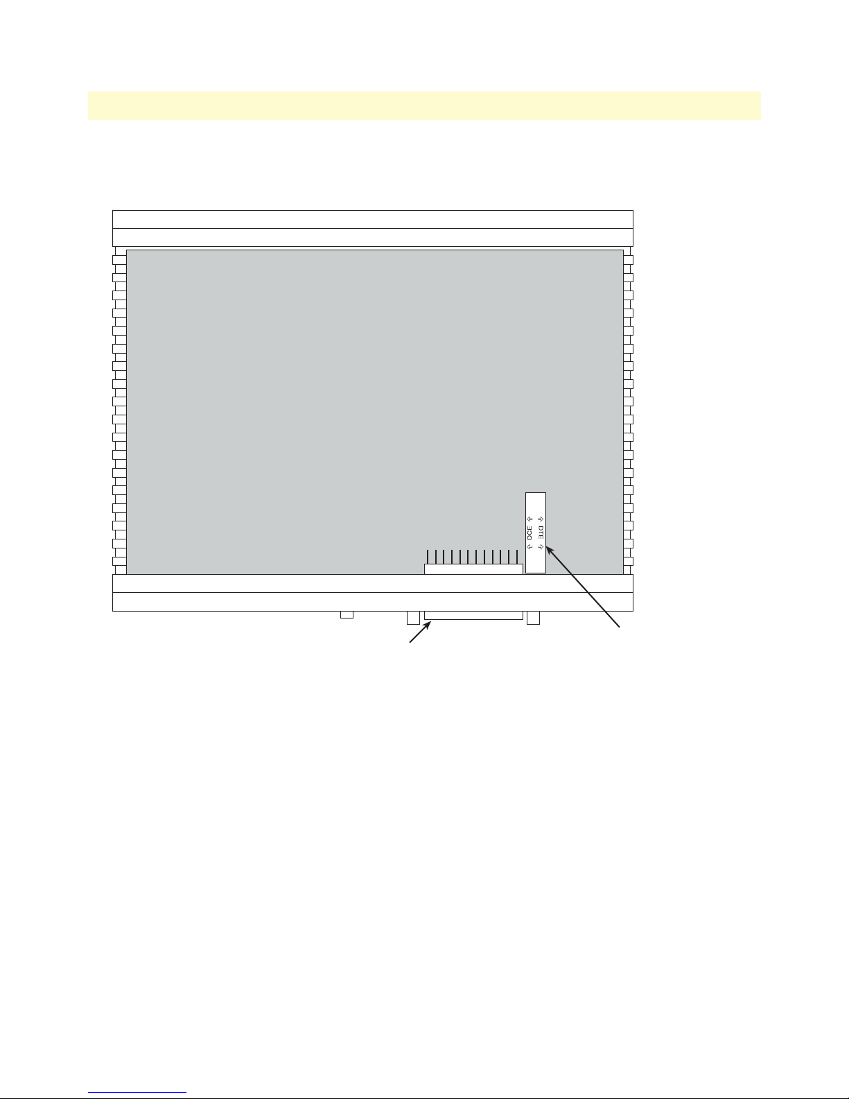
WAN Access Routers Getting Started Guide 3 • Initial configuration
2. Locate the small daughter board on the LR121A board to the right of the DB-9 connector (see figure 9)
shows location of DTE/DCE daughter board).
In this example, the DCE/DTE strap is
X.21 connector
Figure 9. Location of DTE/DCE board
configured for DCE because the DCE label
on the strap is pointed toward the
X.21 connector
3. The DTE/DCE daughter board is installed at the factory with the DTE label and arrows pointing towards
the X.21 connector (DTE configuration). To change to DCE configuration, lift the daughter board from
the connector, turn it around so that the DCE label an arrows point to the X.21 connector, and place it
back on the connector. The X.21 port is now configured as a DCE.
Note When the X.21 port is configured as a DTE, the clocking mode for the port
must be set for external clock.
4. Re-assemble the case.
The interface cable has been installed, go to section “Installing the AC power cord” on page 29.
Hardware installation 27
Page 33
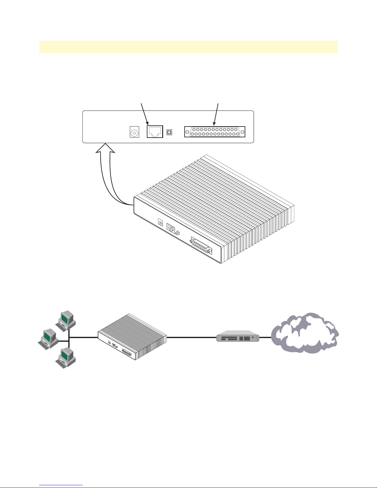
WAN Access Routers Getting Started Guide 3 • Initial configuration
Installing an interface cable on the Black Box LR122A’s V.35 interface port
The Black Box LR122A comes with a V.35 interface presented on a DB-25 female connector (see figure 10).
Ethernet connector
(RJ-45)
10/100
EthernetPower
Power
Crossover
MDI-X
10/100
Ethernet
Crossover
MDI-X
V.35 Interface connector
(DB-25)
V.35 Interface
X.21 Interface
WAN
Figure 10. Rear view of the LR122A showing location of Ethernet and V.35 connectors
Note The Black Box comes with a V.35 tail circuit cable. Use this cable to inter-
connect the Black Box’s V.35 port to a device configured as a DCE.
2635 IPLink
Modem
V.35
1
0
/
1
0
0
P
o
w
e
r
C
r
o
s
s
o
E
v
t
e
h
r
e
r
n
e
M
t
D
I
X
X
.
2
1
W
I
n
A
t
e
N
r
f
a
c
e
Use cable provided
with 2635 IPLink
DCE
Figure 11. Connecting the LR122A to a DCE device
The serial port on the Black Box LR122A is configured as a DCE; it connects directly to a DTE using a standard straight-through V.35 cable.
However, in many applications, the Black Box’s V.35 interface will connect to a DCE (modem or multiplexer),
in this situation use the special cable provided with your LR122A. This DB-25/M35 cable presents the
LR122A’s V.35 interface as a DTE for direct connection to a DCE. (See figure 11.)
Hardware installation 28
Page 34
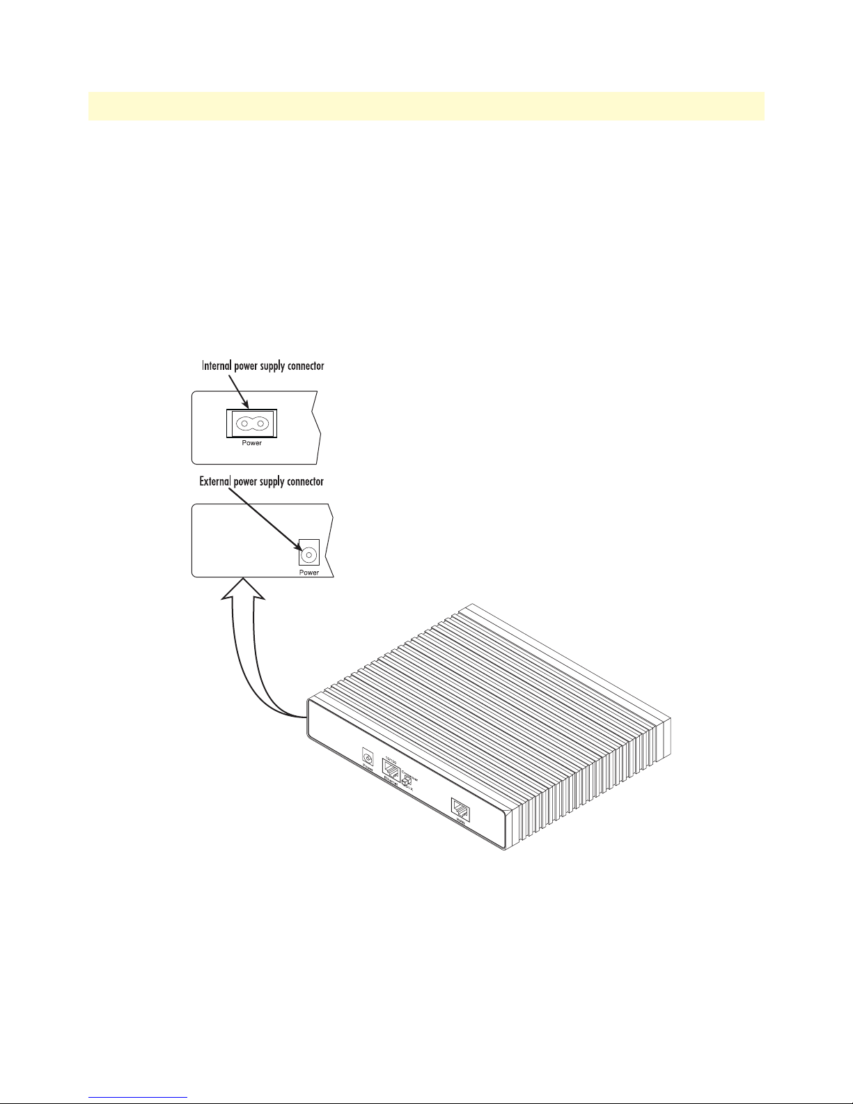
WAN Access Routers Getting Started Guide 3 • Initial configuration
Installing the AC power cord
The WAN Access Router comes with an internal or external power supply. This section describes installing the
power cord into the WAN Access Router. Do the following:
Note Do not connect the other end of the power cord to the power outlet at
this time.
1. If your unit is equipped with an internal power supply, go to step 2. Otherwise, insert the barrel type con-
nector end of the AC power cord into the external power supply connector (see figure 12).
2. Insert the female end of the AC power cord into the internal power supply connector (see figure 12).
Figure 12. Power connector location on rear panel (LR120A shown)
Hardware installation 29
Page 35
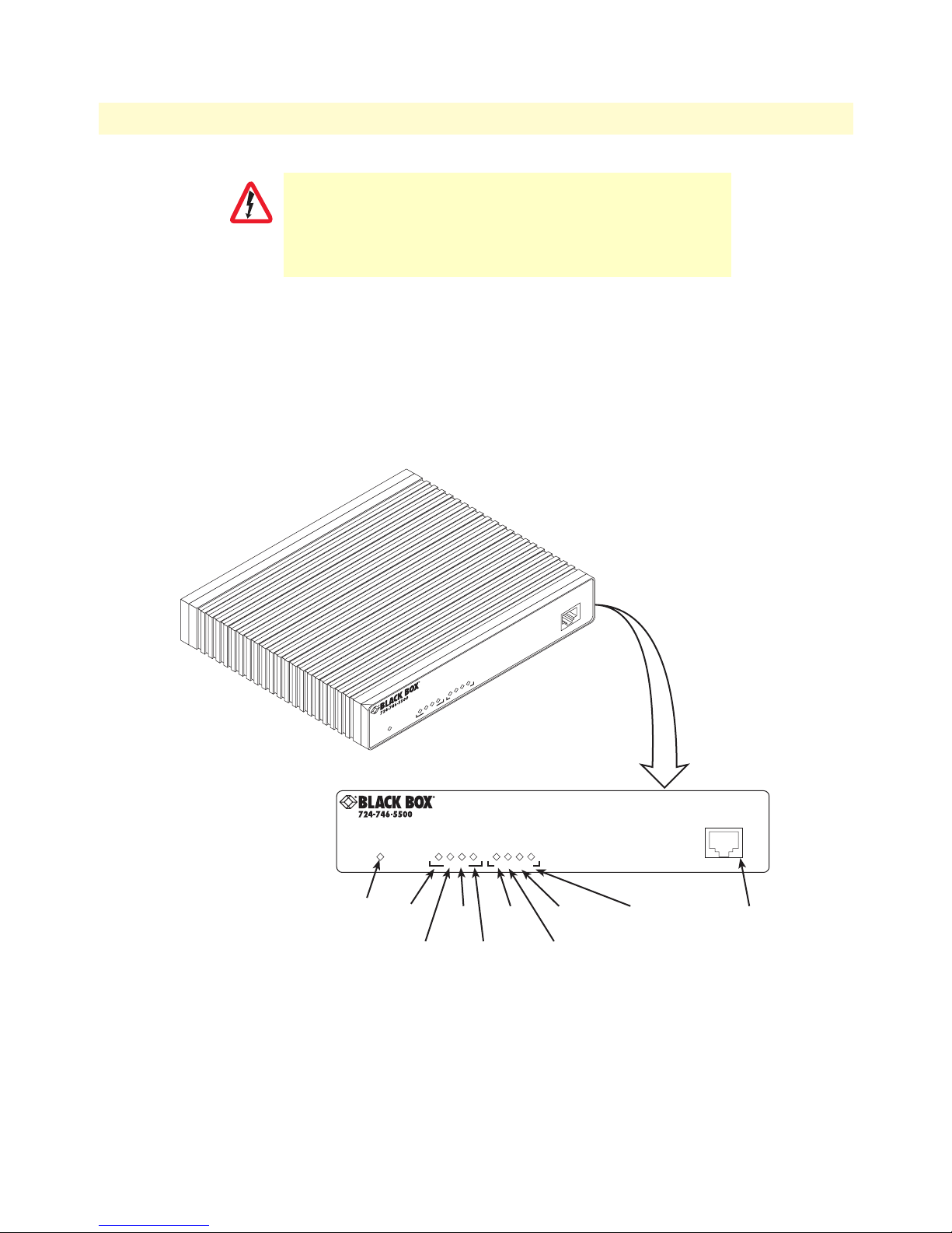
WAN Access Routers Getting Started Guide 3 • Initial configuration
Link
Frame
TD
RD
Link
100M
Tx
Rx
WAN
Ethernet
Power
Console
The WAN Access Router power supply automatically adjusts to
accept an input voltage from 100 to 240 VAC (50/60 Hz).
CAUTION
Verify that the proper voltage is present before plugging the
power cord into the receptacle. Failure to do so could result in
equipment damage.
3. Verify that the AC power cord included with your WAN Access Router is compatible with local standards.
If it is not, contact Black Box Technical Support to find out how to replace it with a compatible
power cord.
4. Connect the male end of the power cord to an appropriate power outlet.
5. Verify that the green Power LED is lit (see figure 13).
6. Unplug the AC power cord from the WAN Access Router to power down the unit.
outer
ccess R
N A
A
W
WAN Access Router
Link
LOSTDRD
Link
LED
100MTxRx
Ethernet
Link
LED
Ethernet Tx
Ethernet
100M
LED
Ethernet Rx
LED
Console
Console
port
Power
LED
Power
WAN Link
LED
WAN LOS
WAN Ethernet
WAN TD
LED
WAN RD
LED
LED
Figure 13. Black Box front panel LEDs and Console port locations (LR120A shown)
Hardware installation 30
Page 36

WAN Access Routers Getting Started Guide 3 • Initial configuration
Installing the Ethernet cable
Do the following:
1. Connect the DB9-RJ45 adapter to the DB-9 serial port on the PC or dumb terminal. Use the RJ45-RJ45
straight-through cable between the adapter and the red marked RJ45 port on the WAN Access Router.
2. Do not connect the router to the Ethernet LAN at this time.
3. On the PC, start a terminal emulation session (such as TeraTerm or HyperTerminal) at 9600 bps, 8 data
bits, 1 stop bit, and no parity.
4. Plug the AC power cord into The WAN Access Router to power up the router.
5. Type superuser for Login:, and press Enter.
6. Then type superuser for the password, press Enter.
7. A message will display, “Login Successful.” By typing the character “?”, all the commands will be displayed.
Login: superuser
Password: *********
Login successful
-->
8. Any commands’ parameters may be seen by entering the command followed by a space and a question
mark.
→
ethernet ?
add
delete
set
show
list
clear
[The following parameters appear]
IP address modification
The first parameter to change is the IP address from the default IP address of 192.168.200.10 to your selected
IP address. Do the following (comments are in brackets […]):
→
ip list interfaces <enter>
IP Interfaces:
ID | Name | IP Address | DHCP | Transport
-------|---------------|------------------|-------------|----------------- 1 | ip1 | 192.168.200.10 | disabled | eth0
---------------------------------------------------------------------------
→
ip set interface ip1 ipaddress 10.10.19.10 255.255.0.0 <enter>
[lists the characteristics of the different interfaces]
[Sets the new IP address which you have selected. The IP
address in this example is for illustrative purposes only.]
→
ip list interfaces <enter>
→
system config save <enter>
→
[To see if the change in IP address is correct]
[To save the new IP address in flash memory.]
The IP address has now been successfully changed.
Hardware installation 31
Page 37
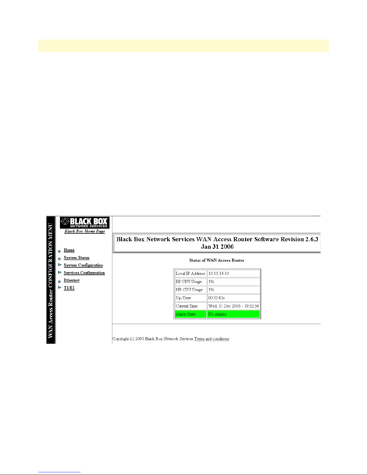
WAN Access Routers Getting Started Guide 3 • Initial configuration
Web operation and configuration
Now that the IP address has been configured for your application, you can complete the configuration using
any standard web browser.
PC configuration
In order to connect the PC to the Ethernet LAN to communicate with The WAN Access Router, the PC’s IP
address should be on the same subnet as the router.
Connect a straight-through Ethernet cable between the PC’s NIC or PCMCIA Ethernet card and an Ethernet
hub or switch.
Web browser
Do the following:
1. Launch a standard web browser such as Netscape Communicator or Internet Explorer (IE).
2. Enter the WAN Access Router’s IP address into the URL or Address field of the browser.
To see the WAN Access Router home page, refer to the following Figures. LR120A is shown in figure 14.
LR121A in figure 15. LR122A in figure 16.
Hardware installation 32
Figure 14. LR120A home page
Page 38
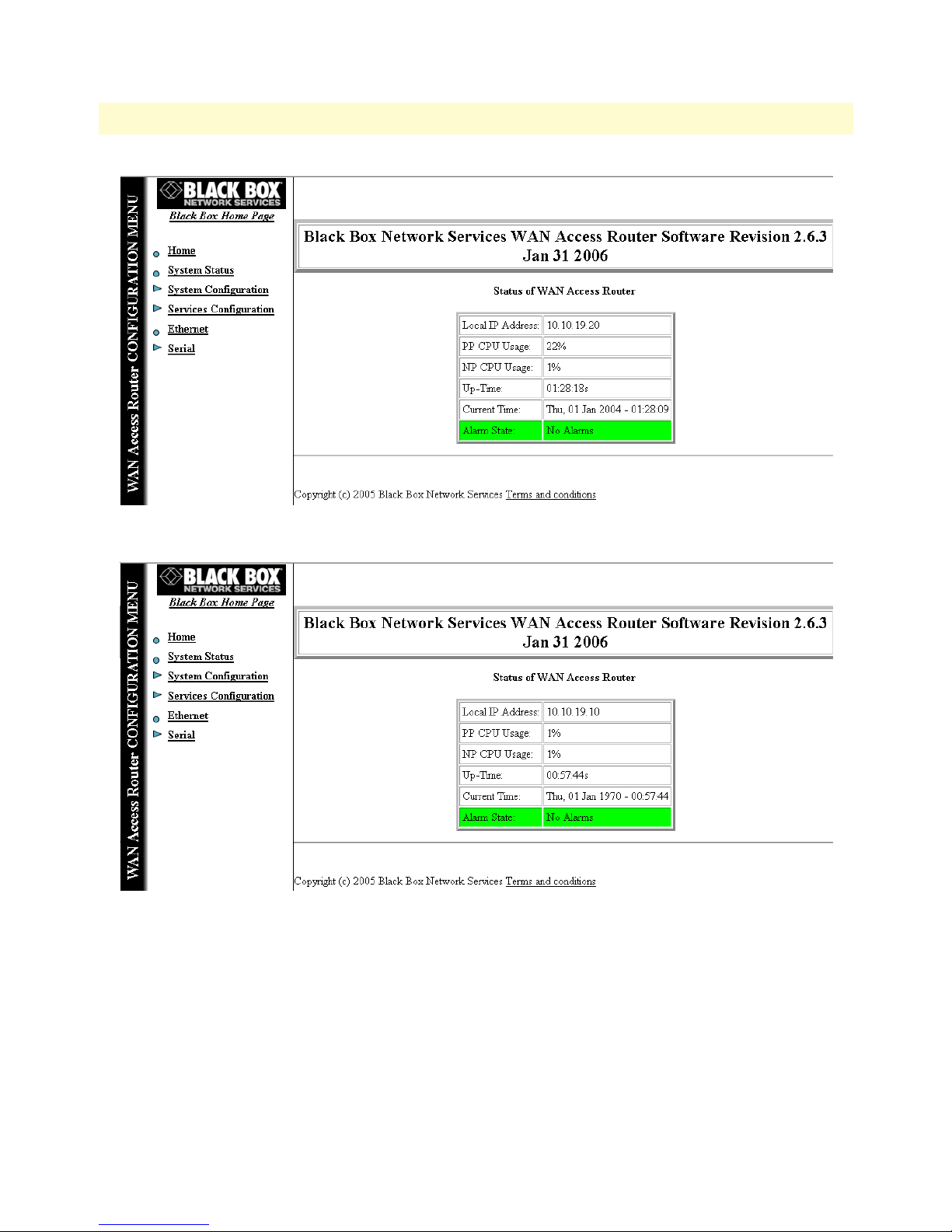
WAN Access Routers Getting Started Guide 3 • Initial configuration
Figure 15. LR121A home page
Hardware installation 33
Figure 16. LR122A home page
Page 39

Chapter 4 Ethernet LAN Port
Chapter contents
Introduction..........................................................................................................................................................35
LAN connections ............................................................................................................................................35
Ethernet Port ..................................................................................................................................................35
34
Page 40
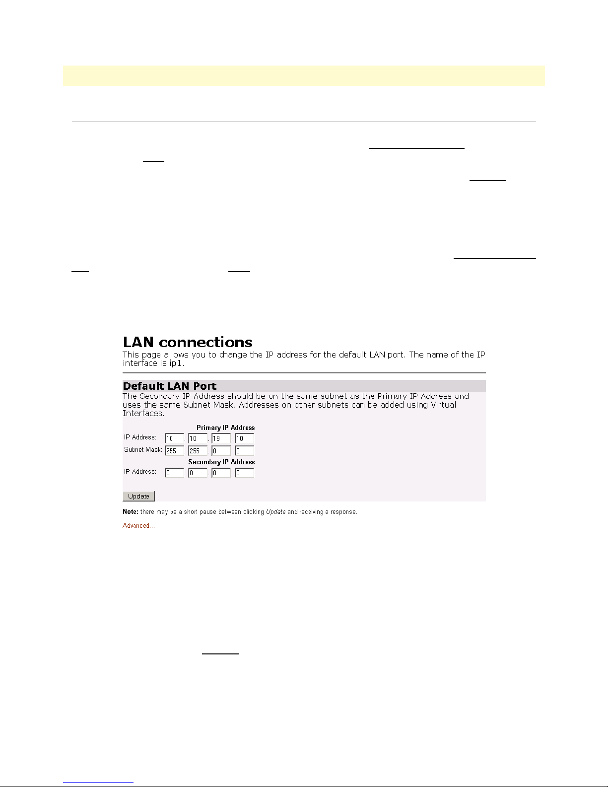
WAN Access Routers Getting Started Guide 4 • Ethernet LAN Port
Introduction
The Ethernet LAN interface/port can be configured with two IP addresses, a primary and a secondary IP
address. The configuration web page is found by following the path -> S
ration Menu) -> L
AN -> ‘Change default LAN port IP address’ (button on the main window).
The Basic and Advanced Port Attributes of the Ethernet LAN port is found by clicking on the Ethernet hyperlink in the Black Box’s Configuration Menu, the narrow window on the left-hand side of the web page. Clicking on the View advanced attributes... hyperlink leads to a webpage with only a few parameters that could be of
interest. They are for controlling auto-negotiation, 100BaseT mode, and Full-duplex mode.
LAN connections
The default LAN port’s IP address and netmask can be changed on this webpage. Go to -> Services Configuration (in the Configuration Menu) -> LAN -> ‘Change default LAN port IP address’ (button on the main
window). (See figure 17.) The primary IP address and mask can be modified here, but if you do, you will no
longer be able to access the Black Box’s webpages with the previous IP address. The interface associated with
the Ethernet is named ip1. You can also configure a secondary IP address to the Ethernet LAN port.
ervices Configuration (in the Configu-
Figure 17. Ethernet LAN port IP address configuration
The secondary IP address must be in the same subnet as the primary IP address. With primary and secondary
IP addresses, you can reach the Black Box’s webpages via either IP address. However you will have to login for
each separate IP address.
Ethernet Port
The Ethernet Port Configuration webpage provides a summary of the Ethernet port’s performance. You reach
it by clicking on the hyperlink E
The Basic Port Attributes webpage displays the most commonly used Ethernet parameters for determining the
performance of the Ethernet port.
Introduction 35
thernet in the Black Box’s Configuration Menu window.
Page 41
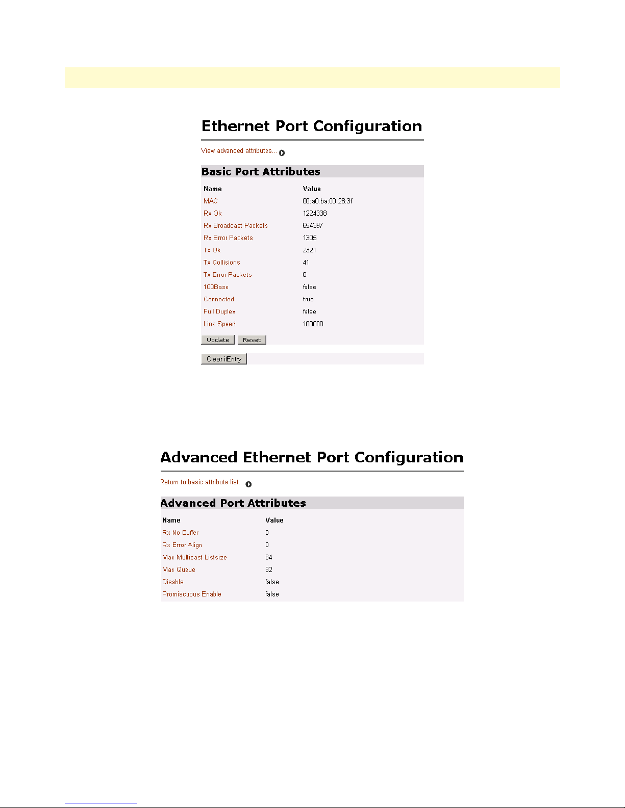
WAN Access Routers Getting Started Guide 4 • Ethernet LAN Port
Figure 18. Basic Ethernet port attributes
For additional statistical parameters and a few configurable parameters, click on the hyperlink View advanced
attributes... (See figure 19.)
Figure 19. Advanced Ethernet port attributes
The three configurable parameters are all either ‘true’ or ‘false.’
• Auto Negotiation: the autonegotiation can be enabled (default) or disabled. In some instances autonegotia-
tion may be problematic if another device on the LAN does not work properly with autonegotiation.
• 100Base Mode: the default is for 100BaseT (‘true’). To configure it for 10BaseT operation at all times, set to
‘false.’
Introduction 36
Page 42

WAN Access Routers Getting Started Guide 4 • Ethernet LAN Port
• Full Duplex Mode: the default value is ‘true’ for Full Duplex operation. Setting it to ‘false’ configures the
Ethernet port to operate only in half-duplex mode.
Rarely do these parameters require a change from their default operation.
Figure 20. Configurable Ethernet parameters
Introduction 37
Page 43

Chapter 5 Serial Port Configuration
Chapter contents
WAN serial port configuration ..............................................................................................................................39
Serial interface .................................................................................................................................................39
Variables ...................................................................................................................................................39
Web interface configuration ......................................................................................................................40
T1/E1 interface configuration .........................................................................................................................40
Configuring the WAN Access Routers LR120A for T1 operation .............................................................41
Web configuration .............................................................................................................................. 41
Configuring the WAN Access Routers LR120A for E1 operation .............................................................42
Web configuration .............................................................................................................................. 42
Configuring the WAN Access Routers LR120A for E1 operation .............................................................43
Web Configuration ............................................................................................................................. 43
38
Page 44

WAN Access Routers Getting Started Guide 5 • Serial Port Configuration
WAN serial port configuration
The WAN Access Routers use a sync.-serial interface (X.21, V.35) or a T1/E1 interface for connection to standard WAN services. Below are the configuration options for the WAN interface.
Serial interface
The serial interface configuration menus allow the user to configure the serial interface for HDLC based connections.
Variables
The following table lists variables that are configurable on the Black Box’s software:
Variable Options Function
Clock Mode Internal The clock setting for the serial interface will determine the
External
RX Clock Invert / TX
Clock Invert
Serial Speed Any n x 64 kbps speed.
TX Data SamplePoint Ext Clk When the unit is running in internal clock mode, the setting of
Inverted The clock invert functions could be used to invert the clocks
Normal
Speed should be entered as the rate, i.e. 512
for 512 kbps or 2048
for 2.048 Mbps
Tx Clk
source of timing for the serial interface only.
that are used on the serial interface. It is not recommended to
change this parameter unless requested by Black Box’ technical support. Keep at default.
Defines the generated speed for internal clock mode operation or the clock that will be received in external clock mode
operation.
TX Data SamplePoint will indicate to the system which clock
to use to sample the in coming data. Some systems require
that the data be sampled on one clock or another. This is
also useful when tail circuits are being created.
When running in the external clock mode this should be set to
Ext Clk.
WAN serial port configuration 39
Page 45

WAN Access Routers Getting Started Guide 5 • Serial Port Configuration
Web interface configuration
The following screen capture shows the variables available to configure the X.21 serial interface.
Figure 21. LR121A X.21 serial port configuration parameters
The next figure shows the LR122A (V.35) serial port configuration parameters.
Figure 22. LR122A V.35 serial port configuration parameters
After the serial port has been configured, go to section “WAN Services” on page 45 for router/bridge and
WAN service configuration.
T1/E1 interface configuration
The WAN Access Routers LR120A is equipped with a user selectable T1/E1 interface. The T1 interface is presented on an RJ-48C (100-ohm) connector, while the E1 interface can use the RJ-48C (120-ohm) or dual
BNC (75-ohm) connectors.
WAN serial port configuration 40
Page 46

WAN Access Routers Getting Started Guide 5 • Serial Port Configuration
The LR120A T1/E1 serial port configuration page appears in figure 23.
Figure 23. LR120A T1/E1 WAN port configuration parameters
Configuring the WAN Access Routers LR120A for T1 operation
Web configuration. Launch Netscape, Internet Explorer or similar web browser, type the IP address of the
LR120A, enter username
superuser and password superuser. From the main page click on the T1/E1 > Configura-
tion. (See figure 24.)
Time Slot Select. For a T1 using all 24 time slots enter 1-24, for fractional T1 enter in any format for example:
1,2,3,5; or 1-5,10-24. Any entry for timeslots above 24 will return an invalid-selection message.
WAN serial port configuration 41
Figure 24. T1 configuration
Page 47

WAN Access Routers Getting Started Guide 5 • Serial Port Configuration
Line Options: Fractional T1
Line Code: The LR120A uses B8Zs and AMI. B8Zs is the most widely used.
Line Build Out: Select from 100 0dB, 100 Ohm -7.5dB, 100 Ohm -15dB, and – 22.5dB. For CSU/DSU
application use 100 0dB option, consult your T1 service provider for more information.
FDL Mode: Options are ANSI-T1-403 and Fdl-none. Consult your T1 service provider if FDL is active on
your T1 link.
Clocking Mode: Internal, Receive Clock (network). In most applications clocking for the LR120A will be derived
from the T1 network, set the unit for Receive Recover unless instructed otherwise by your service provider.
Idle code: Enabled, Disabled. When enabled, the LR120A inserts idle codes (7E hex) on unused timeslots. Set
this option to ‘Disabled’ unless instructed otherwise.
Power Down: Normal, Powered Down. When powered down, T1/E1 transceiver input and output lines will
be set to high impedance to protect the device – set unit to “Normal” for regular operation.
After all options have been selected, click on the Configure and Activate button at the bottom of the screen.
Additionally, save the configuration in non-volatile memory by going to the System Configuration > Save menu.
This concludes the T1 interface configuration via the web browser, go to section “WAN Services” on page 45
for instructions on router/bridge and WAN service configuration.
Configuring the WAN Access Routers LR120A for E1 operation
Web configuration. Launch Internet Explorer or similar web browser, type the IP address of the LR120A, enter
username
superuser and password superuser. From the main page click on the T1/E1 > Configuration. (See
figure 25.)
Figure 25. E1 port configuration
Time Slot Select. For unframed E1 service (Clear Channel) go to the “Line Option” parameter and select
“Clear Channel E1 (G.703).” For a full framed E1 enter 1-31, for partially filled E1 enter the range of
WAN serial port configuration 42
Page 48
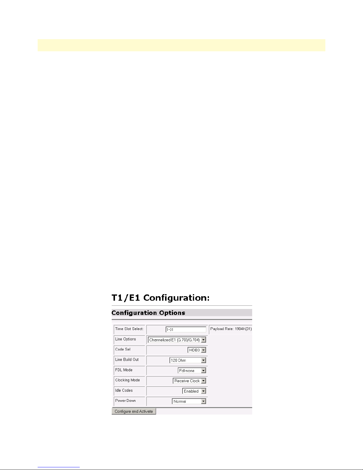
WAN Access Routers Getting Started Guide 5 • Serial Port Configuration
timeslots using the format for example: 1,2,3,5; or 1-5,10-31. Any entry for timeslots above 31 will return and
invalid selection message.
Line Options: Choose from Clear Channel E1(G.703) or Channelized E1(G.703/G.704). Consult with your
service provider which option is required.
Line Code: Choose from AMI or HDB3. Most E1 applications use HDB3.
Line Build Out: Select 120 Ohms if the E1 connection is made via the RJ-48C connector, select 75 Ohm if
the E1 connection is made via the dual BNC connectors.
FDL Mode: FDL is a T1 application, therefore select ‘Fdl- none’ for E1 applications.
Clocking Mode: Options are Internal or Receive Recover Clock (network). In most applications clocking for
the LR120A will be derived from the E1 network, set the unit for Receive Recover unless instructed otherwise
by your service provider.
Idle code: Options are Enabled or Disabled. When idle code is Enabled, the LR120A inserts idle codes (7E
hex) on unused timeslots. Set this option to Disabled unless instructed otherwise.
Power Down: Options are Normal and Powerdown. When powered down, the E1 will put high impedance on
the input and output lines to protect the device—set unit to Normal for regular operation.
Once all options have been selected, click on the Configure and Activate button at the bottom of the screen.
Additionally, save the configuration by going to the System Configuration > Save menu.
This concludes the E1 interface configuration via the web browser, go to section “WAN Services” on page 45
for instructions on router/bridge and WAN service configuration.
Configuring the WAN Access Routers LR120A for E1 operation
Web Configuration. Launch Internet Explorer or similar web browser, type the IP address of the LR120A,
enter username
superuser and password superuser. From the main page click on the T1/E1 > Configuration. (See
figure 25.)
WAN serial port configuration 43
Figure 26. E1 port configuration
Page 49

WAN Access Routers Getting Started Guide 5 • Serial Port Configuration
Time Slot Select. For unframed E1 service (Clear Channel) go to the “Line Option” parameter and select
“Clear Channel E1 (G.703).” For a full framed E1 enter 1-31, for partially filled E1 enter the range of
timeslots using the format for example: 1,2,3,5; or 1-5,10-31. Any entry for timeslots above 31 will return and
invalid selection message.
Line Options: Choose from Clear Channel E1(G.703) or Channelized E1(G.703/G.704). Consult with your
service provider which option is required.
Line Code: Choose from AMI or HDB3. Most E1 applications use HDB3.
Line Build Out: Select 120 Ohms if the E1 connection is made via the RJ-48C connector, select 75 Ohm if
the E1 connection is made via the dual BNC connectors.
FDL Mode: FDL is a T1 application, therefore select ‘Fdl- none’ for E1 applications.
Clocking Mode: Options are Internal or Receive Recover Clock (network). In most applications clocking for
the LR120A will be derived from the E1 network, set the unit for Receive Recover unless instructed otherwise
by your service provider.
Idle code: Options are Enabled or Disabled. When idle code is Enabled, the LR120A inserts idle codes (7E
hex) on unused timeslots. Set this option to Disabled unless instructed otherwise.
Power Down: Options are Normal and Powerdown. When powered down, the E1 will put high impedance on
the input and output lines to protect the device—set unit to Normal for regular operation.
Once all options have been selected, click on the Configure and Activate button at the bottom of the screen.
Additionally, save the configuration by going to the System Configuration > Save menu.
This concludes the E1 interface configuration via the web browser, go to section “WAN Services” on page 45
for instructions on router/bridge and WAN service configuration.
WAN serial port configuration 44
Page 50

Chapter 6 WAN Services
Chapter contents
Introduction..........................................................................................................................................................46
PPP Bridged.......................................................................................................................................................... 46
Remote site configuration ...............................................................................................................................46
Central site configuration ................................................................................................................................47
PPP Routed...........................................................................................................................................................48
Remote site configuration ...............................................................................................................................48
Central site configuration ................................................................................................................................51
LMI Management (Frame Relay links)..................................................................................................................52
LMI configuration ..........................................................................................................................................52
Frame Relay Local Management Interface .................................................................................................52
LMI Configuration Options .....................................................................................................................53
Web Configuration Methods ....................................................................................................................54
Frame Relay bridged..............................................................................................................................................54
Remote site configuration ...............................................................................................................................54
Central site configuration ................................................................................................................................56
Frame Relay Routed ..............................................................................................................................................57
Remote site configuration ...............................................................................................................................57
Central site configuration ................................................................................................................................60
45
Page 51
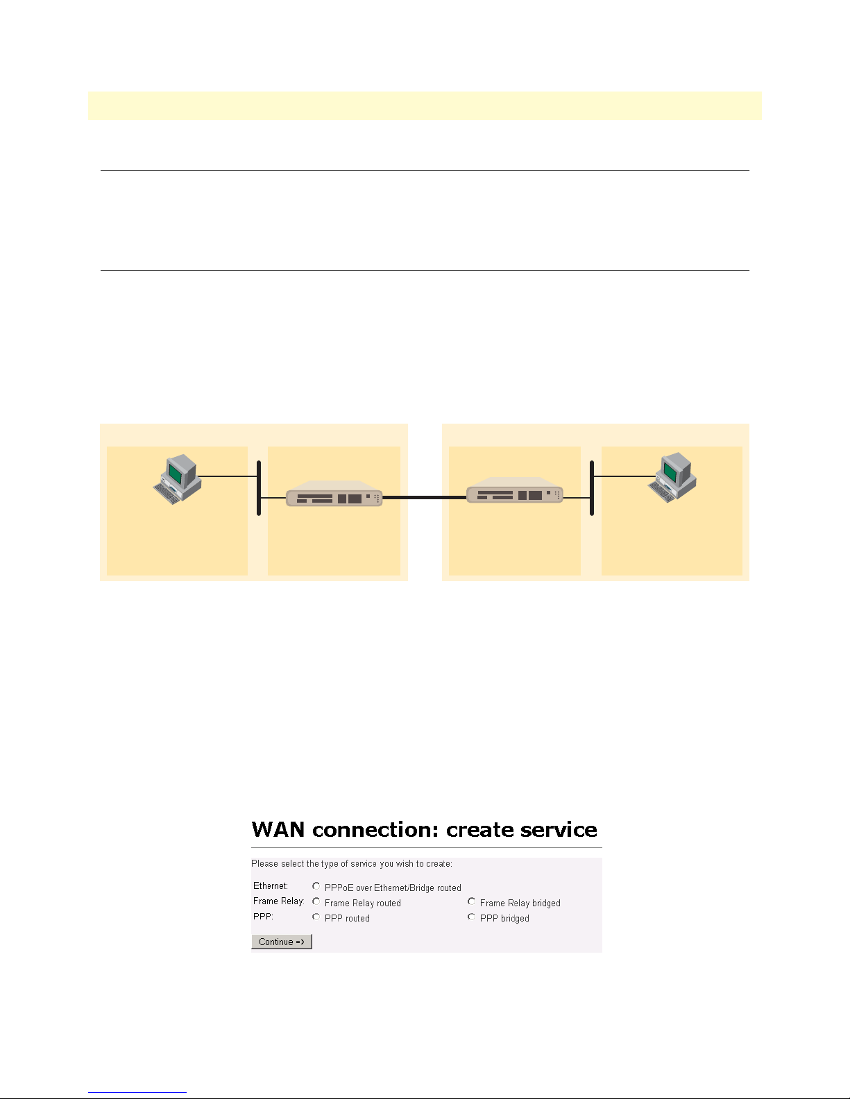
WAN Access Routers Getting Started Guide 6 • WAN Services
Introduction
The WAN Access Routers offer various WAN services for the proper transport encapsulation: Ethernet, Frame
Relay, and PPP options. The Ethernet option is PPPoE, bridged only. Frame Relay and PPP can be used in
either bridged or routed applications.
PPP Bridged
Remote site configuration
The WAN Access Routers can be configured as bridges; in this situation the Black Box typically is at the customer premise or branch office and connects to a router or bridge at a service provider location (this can be
another WAN Access Router). This application shows configuration for two Black Box units in bridged mode.
If using a third party router at the Central side, review the router’s configuration for connection to a remote
bridge. (See figure 27.)
Remote
IP Address: 192.168.100.11/24
Gateway: 192.168.100.2
IPLink routerPC
Figure 27. PPP Bridged Application
IPLink router PC
IP Address: 192.168.100.3IP Address: 192.168.100.2
Central
IP Address: 192.168.100.229/24
IP Address: 192.168.100.229/24IP Address: 192.168.100.11/24
Gateway: 192.168.100.3
WAN Access Routers (Remote)
First configure the IP address on the Ethernet port (interface ip1) for 192.168.100.2/24 via the command line
(CLI). Once this is done, you can complete the configuration using the web pages.
1. Bring up the web-page management system on your browser by entering the IP address of Black Box.
2. On the Menu, go to Services Configuration, then to WAN. Delete the factory default WAN services
already defined.
3. Click on Create a new service in the main window, select “PPP bridged” and click on the Configure button.
Introduction 46
Figure 28. WAN services’ options
Page 52
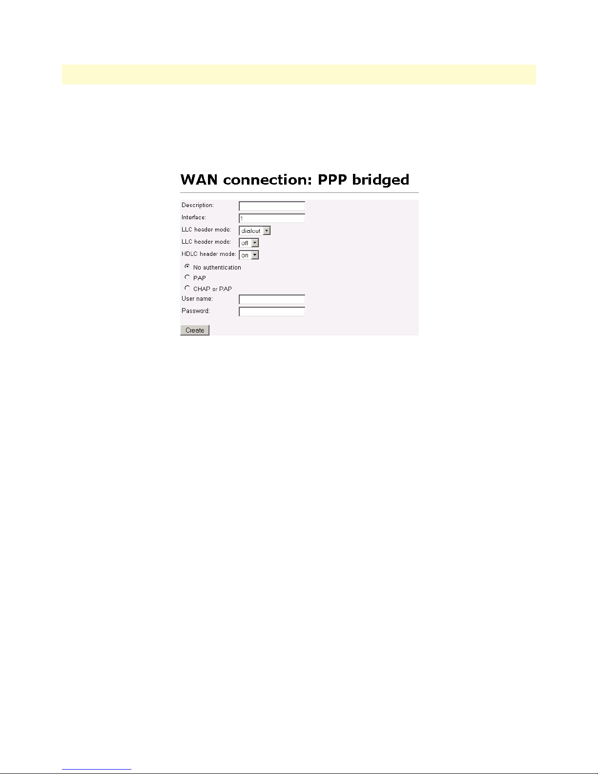
WAN Access Routers Getting Started Guide 6 • WAN Services
4. In the Description field, enter the description you wish. This is a mandatory field. Without a description,
you cannot create the WAN service.
Figure 29. Configuring PPP bridged WAN service
Verify the settings to be:
• Interface = 1
• LLC header mode = dialout
• LLC header mode = off
• HDLC header mode = on
• No authentication
• Leave User name and Password blank.
Click on Create.
Central site configuration
If the central site also has an Black Box, you may configure as described in this section. Refer to the web page
images for the Remote Black Box configuration above.
In this example, the IP address of interface ip1 is changed to 192.168.100.3/24.
1. Bring up the web-page management system on your browser by entering the IP address of the Black Box
2. On the Menu, go to Services Configuration, then to WAN. Delete the factory default WAN services
already defined.
3. Click on Create a new service in the main window, select PPP bridged and click on the Continue button.
4. In the Description field, enter the description you wish, for example, PPP Bridged.
PPP Bridged 47
Page 53

WAN Access Routers Getting Started Guide 6 • WAN Services
Verify the settings to be:
• Interface = 1
• LLC header mode = dialout
• LLC header mode = off
• HDLC header mode = on
• No authentication
• Leave User name and Password blank.
Click on Create.
PPP Routed
This application shows configuration for two Black Box units in PPP routed mode. An Black Box may be used
as the router at the Central site, but it is not necessary. You can use a third party router as long as it supports
PPP routed operation. If using a third party router at the Central site, review the router’s configuration. (See
figure 30.)
Remote site configuration
First configure the IP address on the Ethernet port (interface ip1) for 192.168.200.2/24 via the command line
(CLI). The PC will be on the same subnet as the Black Box Ethernet port. Once this is done, you can complete
the configuration using the web pages.
1. Bring up the web-page management system on your browser by entering the IP address of the Black Box.
2. On the Menu, go to Services Configuration, then to WAN. Delete the factory default WAN services
already defined.
3. Click on Create a new service in the main window, select “PPP routed” and click on the Continue button.
In the Description field, enter the description you wish. In this example, it is called PPP Routed.
– Description: PPP Routed
– Interface: 1
PPP Routed 48
Figure 30. PPP Routed Application
Page 54
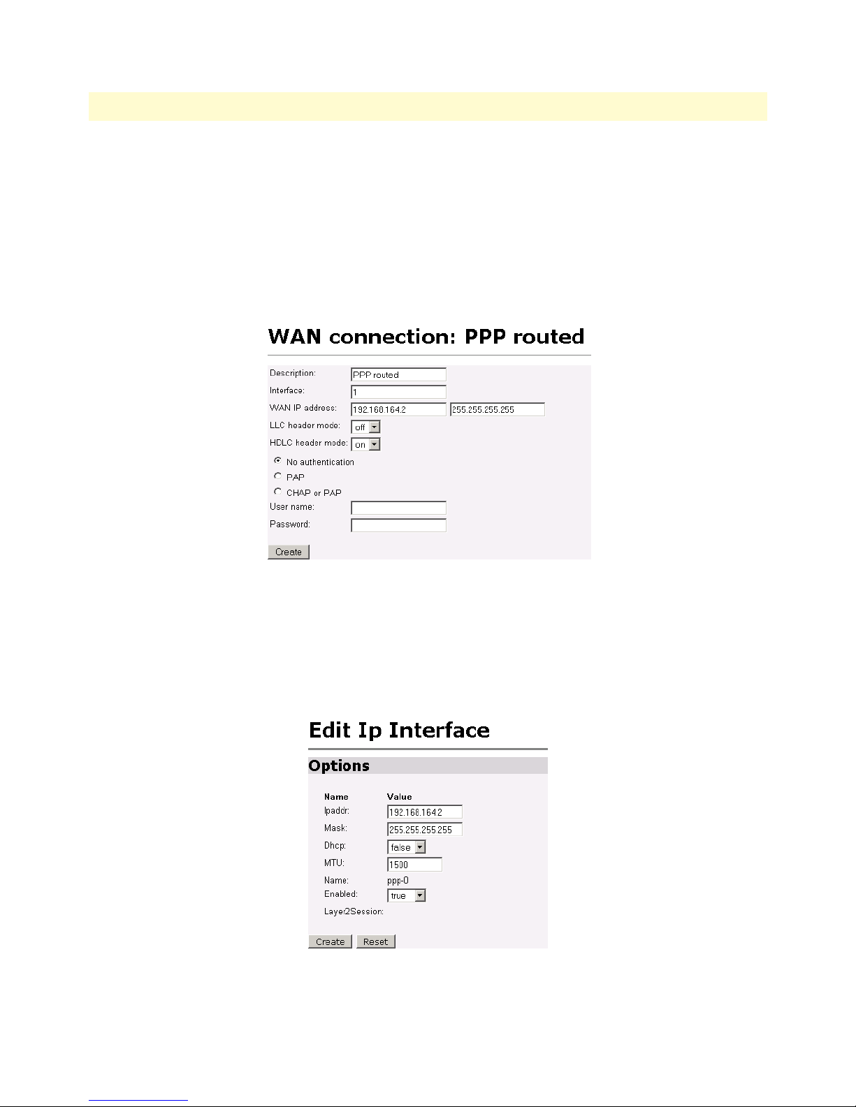
WAN Access Routers Getting Started Guide 6 • WAN Services
– WAN IP address: 192.168.164.2 255.255.255.255
– LLC Header Mode: off
– HDLC Header Mode: ON
– No authentication
– Username: [blank]
– Password: [blank]
Figure 31. PPP Routed Configuration menu
4. Click on Create.
5. Go to Services Configuration > WAN > Edit... (for PPP routed) > Edit ‘IP Interface’ > Ipaddr: [enter the
WAN IP Address and Mask, in this example = 192.168.164.2 and 255.255.255.255]. (See figure 32.)
6. Click on Create.
Figure 32. Edit IP address of WAN port
PPP Routed 49
Page 55
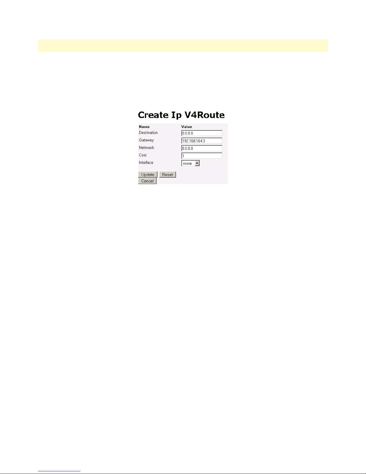
WAN Access Routers Getting Started Guide 6 • WAN Services
7. Click on Services Configuration > IP Routes > Create new Ip V4 Route. Create the gateway to the remote
router by entering the WAN IP address of the remote router, in this example, enter 192.168.164.3 in the
Gateway field. (See figure 33.)
8. Click the Update button.
Figure 33. Configuring the gateway
The other fields should be:
• Destination: 0.0.0.0
• Gateway: 192.168.164.3
• Mask: 0.0.0.0
• Cost: 1
• Interface: [blank]
You can see the status of the PPP link by going to the ‘Edit PPP’ web page and paging down until you see the
Summary description. In figure 34, the PPP link is in the Establishment phase. To get to the Edit PPP web
page, follow this path: Services Configuration > WAN > Edit... > Edit ‘PPP’
PPP Routed 50
Page 56
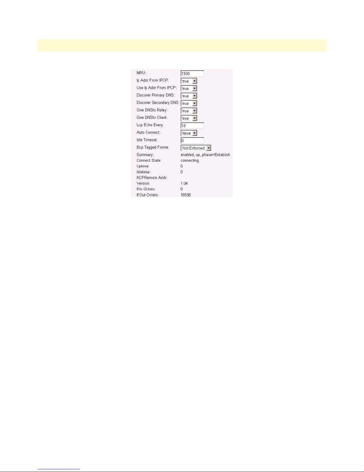
WAN Access Routers Getting Started Guide 6 • WAN Services
Figure 34. PPP link status
Central site configuration
If the router at the ISP or Central site is another WAN Access Routers, follow the instructions below. If not,
consult your third party router user manual for configuration.
See the web pages for the desktop above. Some configurable parameters are different although the process is
the same.
Configure the IP address of the Ethernet port (interface ip1) to be 192.168.172.3/24. The PC, connected to
the Ethernet LAN directly, must be on the same subnet in order to access the configuration web pages. In this
example, the PC’s IP address is 192.168.172.229/24. Notice that this subnet differs from the subnets of the
WAN service link and also the Ethernet port of the remote Black Box (which we just configured).
1. Bring up the web-page management system on your browser by entering the IP address of the Black Box,
192.168.172.3.
2. On the Menu, go to Service Configuration, then to WAN. Delete the default WAN services already defined.
3. Click on Create a new service in the main window, select “PPP routed” and click on the Continue button.
In the Description field, enter the description. In this example, it is called PPP Routed.
– Description: PPP Routed
– Interface: 1
– WAN IP address and Mask: 192.168.164.3 255.255.255.255
– LLC Header Mode: off
– HDLC Header Mode: ON
– No authentication
PPP Routed 51
Page 57

WAN Access Routers Getting Started Guide 6 • WAN Services
– Username: [blank]
– Password: [blank]
Click on the Create button.
4. Go to Services Configuration > WAN > Edit... (for PPP routed) > Edit ‘IP Interface’ > Ipaddr: [enter the
WAN IP Address and Mask, in this example = 192.168.164.3 and 255.255.255.255].
5. Click on Create.
6. Go to Configuration Menu > Configuration > IP Routes > Click on Create new Ip V4 Route.
7. Create the gateway to the remote Black Box by entering the WAN IP address of the remote Black Box, in
this example, enter 192.168.164.2 in the Gateway field
8. Click OK.
The other fields should be:
– Destination:0.0.0.0
– Gateway:192.168.164.2
– Mask:0.0.0.0
– Cost 1
– Interface: [blank]
You can see the status of the PPP link by going to the ‘Edit PPP’ web page and paging down until you see the
“Summary” description. To get to the ‘Edit PPP’ web page, follow this path: Services Configuration > WAN >
Edit... > Edit ‘PPP’
LMI Management (Frame Relay links)
LMI configuration
Frame Relay Local Management Interface
The Frame Relay Local Management Interface (LMI) is a mechanism that two separate frame relay systems can
use to communicate the status of the interface. The LMI interface allows dynamic updates on the status of the
DLCI connections and the congestion state of the network. The Black Box implements all three versions of
LMI available within the frame relay network. These are defined in table 4:
Table 4. LMI Implementation on the Black Box
Protocol Specification Options Available
LMI Frame Relay Forum Implementation Agreement
(IA) FRF.1 superseded by FRF.1.1
Annex D ANSI T1.617 User Side
Annex A ITU Q.933 referenced in FRF.1.1 User Side
User Side
LMI Management (Frame Relay links) 52
Page 58

WAN Access Routers Getting Started Guide 6 • WAN Services
LMI Configuration Options
The Frame Relay Local Management Interface is configurable through either the CLI or web interface on the
WAN Access Routers. The following variables are available for configuration.
• managementType: (Default Value: no_maintenance) the managementType variable defines the LMI proto-
col that will be used from the table above. The following options are available.
- no_maintenance: No maintenance interface will be used for this frame relay connection.
- ITU Network: The ITU Q.933 protocol will be used. The unit will operate as the Network side of the
connection.
- ITU User: The ITU Q.933 protocol will be used. The unit will operate as the User side of the
connection.
- ITU Both: (NNI) The ITU Q.933 protocol will be used. The unit will operate as both the Network and
User side of the connection.
- ANSI Network: The ANSI T1.617 protocol will be used. The unit will operate as the Network side of the
connection
- ANSI User: The ANSI T1.617 protocol will be used. The unit will operate as the User side of the
connection
- ANSI Both: (NNI) The ANSI T1.617 protocol will be used. The unit will operate as both the Network
and User side of the connection.
• Management State: Defines the current state of the DTE side LMI. Possible options are as follows:
- Mgt_Port_DOWN – Currently the LMI on the DTE side is DOWN
- Mgt_Port_UP – Currently the LMI on the DTE side is UP
• Management Auto Start: (Default Value: FALSE) The management Auto Start variable allows the user to
start the LMI session before any DLCI connections are created within the unit. If this variable is set to
FALSE, the LMI session will begin when the first DLCI channel is created. If this variable is set to TRUE
the LMI session will begin immediately.
• Full Report Cycle: (Default Value: 6) This variable represents the N391 protocol value
• User Max Errors: (Default Value: 3) Network side N392 protocol value
• Net Max Errors: (Default Value: 3) Network side N392 protocol value
• User Error Window Size: (Default Value: 4) User side N393 protocol value
• Net Error Window Size: (Default Value: 4) Network side N393 protocol value
• T391_Value: (Default Value: 10) This variable sets the T391 timers in seconds.
• T392_Value: (Default Value: 16) This variable sets the T392 timers in seconds.
LMI Management (Frame Relay links) 53
Page 59
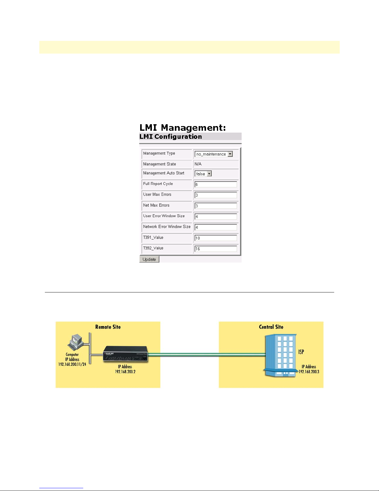
WAN Access Routers Getting Started Guide 6 • WAN Services
Web Configuration Methods
The following documentation defines how to configure the Frame Relay Local Management Interface using
the Web Interface on the WAN Access Routers.
All LMI configuration variables are contained under the “LMI Management” window found through the Ser-
vices Configuration >LMI Management link. The following screen shows the configuration variables available.
Figure 35. LMI Configuration webpage
Frame Relay bridged
Figure 36 shows configuration for two Black Box units in bridged mode. If using a third party router at the
Central site, review the router’s configuration for connection to a remote bridge.
Figure 36. Frame Relay bridged application
Remote site configuration
First configure the IP address of the Ethernet port (interface ip1) via the command line (CLI) for
192.168.200.2/24. The PC must be on the same subnet for configuring the Black Box via the web pages.
1. Bring up the web-page management system on your browser by entering the IP address of the Black Box.
Frame Relay bridged 54
Page 60

WAN Access Routers Getting Started Guide 6 • WAN Services
2. On the Menu, go to Services Configuration, then to WAN. Delete the factory default WAN services
already defined.
3. Click on Create a new service in the main window, select “Frame Relay bridged” and click on Continue.
4. Enter the description for the circuit in the Description field. This is a mandatory field. Without a descrip-
tion you cannot create a WAN service.
5. Click on Create a new service in the main window, select Frame relay bridged and click on the Configure
button. (See figure 37.)
Figure 37. Frame Relay bridged creation
6. Click along the following path: Services Configuration > WAN > ‘Edit...’ Then click on Edit ‘Frame Relay
Channel’. (See figure 38.) The configurable parameters are:
– DLCI: Consult with your service provider for the DLCI number required.
– Encapsulation type: Bridged Ether (Defines the RFC 1490 encapsulation type to be used by the chan-
nel. In some instances you may need to choose another type. Consult your service provider.)
– RX Max PDU: 8192 Receive side max PDU, default 8192 (normally not changed from default)
– TX Max PDU: 8192 Transmit side max PDU, default 8192(normally not changed from default)
– Channel segment size. The channel segment size is used to define fragmentation of the packets based on
the Frame Relay Forum IA FRF.12. If this variable is set to 0 then FRF.12 “Frame Relay Fragmentation”
will be disabled, if set to any other value it will set the fragmentation size used.
– Port: Defines the port that should be used to setup the Frame Relay Connection. For routed applica-
tions the port should be set to “frf”, for bridged applications the port should be set to “fr”.
Click on the Create button.
Frame Relay bridged 55
Page 61

WAN Access Routers Getting Started Guide 6 • WAN Services
Figure 38. Frame Relay Channel configuration
Central site configuration
Note If you are using a Black Box at the Central location, follow the instructions
below, otherwise refer to your third party router documentation
for configuration.
See the web pages for the Black Box above. Some parametric values will differ, but the process remains
the same.
First configure the IP address of the Ethernet port (interface ip1) via the command line (CLI) for
192.168.172.3/24. The PC (IP address 192.168.172.229) must be on the same subnet for configuring the
Black Box via the web pages.
1. Bring up the web-page management system on your browser by entering the IP address of the Black Box.
2. On the Menu, go to Services Configuration, then to WAN. Delete the factory default WAN services already
defined.
3. Click on Create a new service in the main window, select “Frame Relay bridged” and click on Continue.
4. Enter the description for the circuit in the Description field. This is a mandatory field. Without a descrip-
tion you cannot create a WAN service.
5. Click on Create a new service in the main window, select Frame relay bridged and click on the Configure
button.
6. Click along the following path: Services Configuration > WAN > ‘Edit...’ Then click on Edit ‘Frame Relay
Channel’. The configurable parameters are:
– DLCI: Consult with your service provider for the DLCI number required.
– Encapsulation type: Bridged Ether (Defines the RFC 1490 encapsulation type to be used by the chan-
nel. In some instances you may need to choose another type. Consult your service provider.)
– RX Max PDU: 8192 Receive side max PDU, default 8192 (normally not changed from default)
Frame Relay bridged 56
Page 62
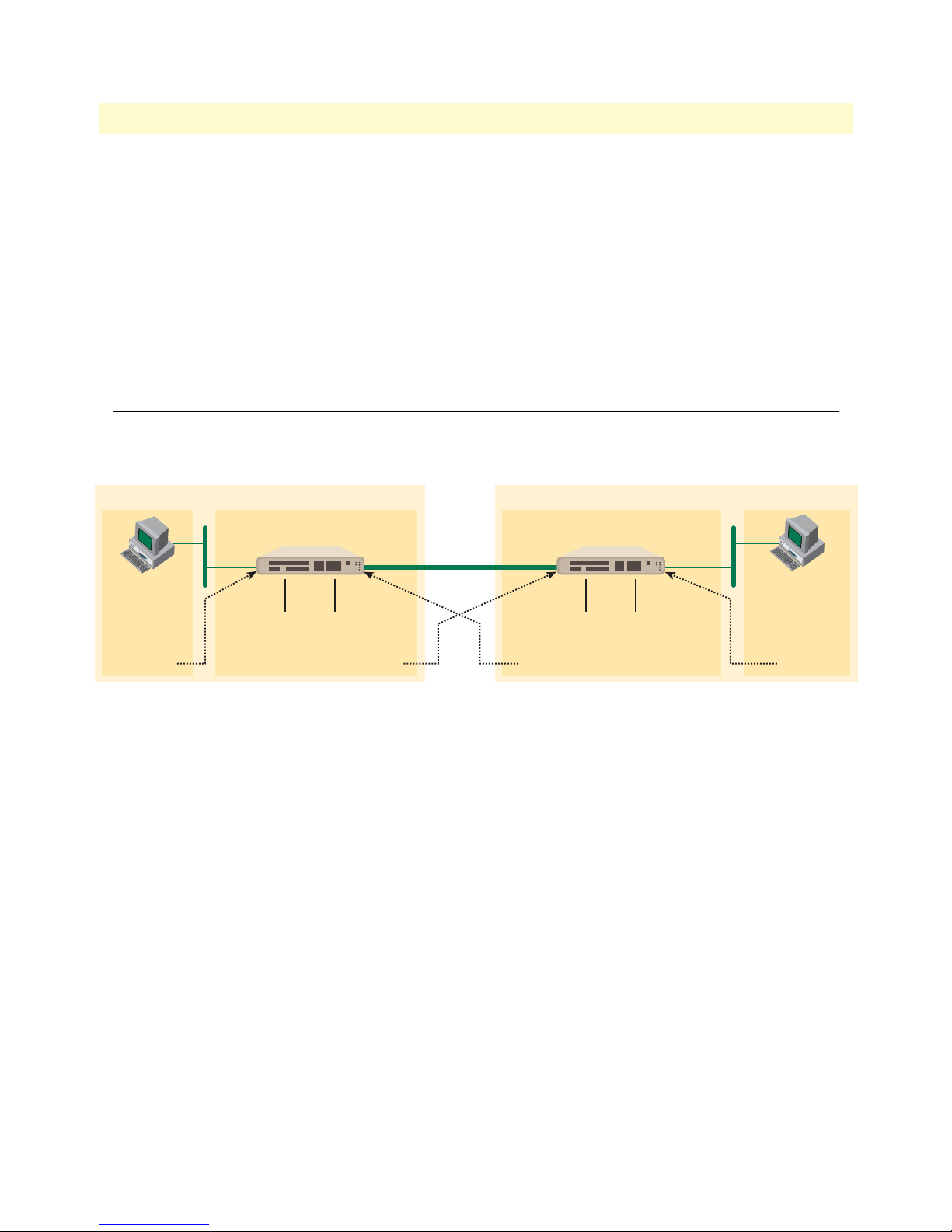
WAN Access Routers Getting Started Guide 6 • WAN Services
– TX Max PDU: 8192 Transmit side max PDU, default 8192(normally not changed from default)
– Channel segment size. The channel segment size is used to define fragmentation of the packets based on
the Frame Relay Forum IA FRF.12. If this variable is set to 0 then FRF.12 “Frame Relay Fragmentation”
will be disabled, if set to any other value it will set the fragmentation size used.
– Port: Defines the port that should be used to setup the Frame Relay Connection. For routed applica-
tions the port should be set to “frf”, for bridged applications the port should be set to “fr”.
Click on the Create button.
This conclude the central site configuration.
Frame Relay Routed
This application shows the configuration for two Black Box units in routed mode. If using a third party router
at the Central site, review the router’s configuration for connection to a remote bridge.
Central
IP Address
192.168.172.3
PC
IP Address
192.168.172.229
Gateway
192.168.172.3
PC
IP Address
192.168.100.11
Gateway
192.168.100.2
Remote
Remote
IP Address
192.168.100.2
WAN IP Address
192.168.164.2
WAN Gateway
192.168.164.3
Central
Frame
Relay
WAN IP Address
192.168.164.3
WAN Gateway
192.168.164.2
Figure 39. Frame Relay routed application
Remote site configuration
First configure the IP address of the Black Box’s Ethernet port (interface ip1) via the command line (CLI) for
192.168.100.2/24. The PC must be on the same subnet for configuring the Black Box via the web pages.
1. Bring up the web-page management system on your browser by entering the IP address of the Black Box.
2. On the Menu, go to Services Configuration, then to WAN. Delete the factory default WAN services
already defined.
3. Click on Create a new service in the main window, select “Frame Relay routed” and click on Continue.
Frame Relay Routed 57
Page 63

WAN Access Routers Getting Started Guide 6 • WAN Services
4. Enter the description for the circuit in the Description field. This is a mandatory field. Without a descrip-
tion you cannot create a WAN service. (See figure 40.)
Figure 40. Frame Relay routed configuration
– Description: FR routed
– DLCI. Enter DLCI number. Consult with your service provider for the DLCI number required.
– Encapsulation Method. Defines the RFC1490 encapsulation type that will be used by the channel.
Choose the encapsulation method best suited for your network needs from the following options:
– Routed IP (default value)
–Raw
– WAN IP address. Enter the IP address assigned to the WAN port (V.35, X.21, or T1/E1)
– Enable NAT on this interface. In this example leave this option blank
5. Click the Create button.
6. Go to System Configuration > WAN > Edit (for Frame Relay Routed service) > Edit ‘IP Interface’
7. Enter the WAN IP Address, in this example = 192.168.164.2, and click on the Create button.
8. From the ‘IP Interface’ web page, click on Edit ‘Frame Relay’, then click on Edit ‘Frame Relay Channel’ (see
figure 41.)
Frame Relay Routed 58
Page 64
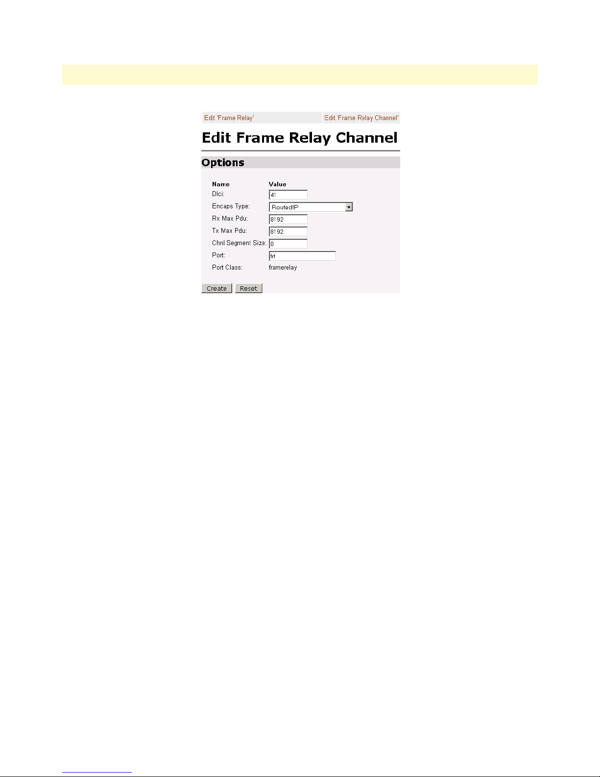
WAN Access Routers Getting Started Guide 6 • WAN Services
Figure 41. Frame Relay Channel - Routed configuration
Edit Frame Relay Channel
Enter the appropriate information in the following fields:
• Dlci: Consult with your service provider for the DLCI number required, in this example use 45.
• Encapsulation Method: Defines the RFC1490 encapsulation type that will be used by the channel. Chose
the encapsulation method best suited for your network. In this example enter RoutedIp
• RX Max PDU: Enter the number of receive side max PDU, in this example it is the default 8192
• TX Max PDU: Enter the number of transmit side max PDU, in this example it is the default 8192
• Channel segment size. The channel segment size is used to define fragmentation of the packets based on
the Frame Relay Forum IA FRF.12. If this variable is set to 0 then FRF.12 “Frame Relay Fragmentation”
will be disabled, if set to any other value it will set the fragmentation size used.
• Port: Defines the port that should be used to setup the Frame Relay Connection. For routed applications
the port should be set to “frf”. (For bridged applications the port should be set to “fr”.)
1. Click on the Create button.
2. Click on System Configuration > IP Routes > Create new Ip V4 Route
3. Create the gateway to the remote Black Box by entering the WAN IP address of the remote Black Box, in
this example, enter 192.168.164.3 in the Gateway field.
The other fields should be:
– Destination: 0.0.0.0
– Gateway: 192.168.164.3
– Mask: 0.0.0.0
Frame Relay Routed 59
Page 65

WAN Access Routers Getting Started Guide 6 • WAN Services
– Cost: 1
– Interface: frame-0
Figure 42. IP route for Frame Relay routed application
4. Click on the Update button.
This concludes the configuration of the remote site. Be sure to save the configuration in non-volatile memory
by System Configuration > Save > Click on Save in the main window.
Central site configuration
Note If you are using an Black Box at the central location, follow the instructions
below, otherwise refer to your third party router documentation
for configuration.
First configure the IP address of the Black Box’s Ethernet port (interface ip1) via the command line (CLI) for
192.168.172.3/24. The PC must be on the same subnet for configuring the Black Box via the web pages.
1. Bring up the web-page management system on your browser by entering the IP address of the Black Box.
2. On the Menu, go to Services Configuration, then to WAN. Delete the factory default WAN services already
defined.
3. Click on Create a new service in the main window, select “Frame Relay routed” and click on Continue.
4. Enter the description for the circuit in the Description field. This is a mandatory field. Without a descrip-
tion you cannot create a WAN service.
– Description: FR routed
– DLCI. Enter DLCI number. Consult with your service provider for the DLCI number required.
– Encapsulation Method. Defines the RFC1490 encapsulation type that will be used by the channel.
Choose the encapsulation method best suited for your network needs from the following options:
– Routed IP (default value)
–Raw
Frame Relay Routed 60
Page 66

WAN Access Routers Getting Started Guide 6 • WAN Services
– WAN IP address. Enter the IP address assigned to the WAN port (V.35, X.21, or T1/E1)
– Enable NAT on this interface. In this example leave this option blank
5. Click the Create button.
6. Go to System Configuration > WAN > Edit (for Frame Relay Routed service) > Edit ‘IP Interface’
7. Enter the WAN IP Address, in this example = 192.168.164.3, and click on the Create button.
8. From the ‘IP Interface’ web page, click on Edit ‘Frame Relay’, then click on Edit ‘Frame Relay Channel’
Edit Frame Relay Channel
Enter the appropriate information in the following fields:
• Dlci: Consult with your service provider for the DLCI number required, in this example use 45.
• Encapsulation Method: Defines the RFC1490 encapsulation type that will be used by the channel. Chose
the encapsulation method best suited for your network. In this example enter RoutedIp
• RX Max PDU: Enter the number of receive side max PDU, in this example it is the default 8192
• TX Max PDU: Enter the number of transmit side max PDU, in this example it is the default 8192
• Channel segment size. The channel segment size is used to define fragmentation of the packets based on
the Frame Relay Forum IA FRF.12. If this variable is set to 0 then FRF.12 “Frame Relay Fragmentation”
will be disabled, if set to any other value it will set the fragmentation size used.
• Port: Defines the port that should be used to setup the Frame Relay Connection. For routed applications
the port should be set to “frf”. (For bridged applications the port should be set to “fr”.)
1. Click on the Create button.
2. Click on System Configuration > IP Routes > Create new Ip V4 Route
3. Create the gateway to the remote Black Box by entering the WAN IP address of the remote Black Box, in
this example, enter 192.168.164.3 in the Gateway field.
The other fields should be:
– Destination: 0.0.0.0
– Gateway: 192.168.164.2
– Mask: 0.0.0.0
– Cost: 1
– Interface: frame-0
4. Click on the Update button.
This concludes the configuration of the remote site. Be sure to save the configuration in non-volatile memory
by System Configuration > Save > Click on Save in the main window.
Frame Relay Routed 61
Page 67

Chapter 7 Security
Chapter contents
Introduction..........................................................................................................................................................63
Configuring the router ..........................................................................................................................................63
Configuring the security interfaces.........................................................................................................................65
Configuring security policies ...........................................................................................................................66
Deleting a security Policy ..........................................................................................................................67
Enabling the Firewall.............................................................................................................................................67
Firewall Portfilters .................................................................................................................................................68
Security Triggers....................................................................................................................................................69
Intrusion Detection System (IDS).........................................................................................................................70
Introduction to NAT ............................................................................................................................................73
Enabling NAT ................................................................................................................................................73
Global address pool and reserved map .............................................................................................................73
62
Page 68

WAN Access Routers Getting Started Guide 7 • Security
Introduction
Security provides the ability to setup and enforce security policies. The policies define the types of traffic permitted to pass through a gateway, either inbound, outbound, or both, and from which origins the traffic may
be allowed to enter.
Within the security configuration is a stateful firewall. A stateful firewall utilizes a security mechanism to maintain information concerning the packets it receives. This information is used for deciding dynamically whether
or not a packet may pass through.
Port filters are rules that determine how a packet should be handled. The rules define the protocol type, the
range of source and destination port numbers and an indication whether the packet is allowed or not.
Security triggers are used with applications that require and create separate sessions. The most common example is FTP. An FTP client establishes a connection to a server using port 21, but data transfers are done on a
separate connection or port. The port number, and who makes the connection, can vary depending on the
FTP client. To allow FTP to work without triggers, you would need to set up port filters allowing the correct
port numbers through. This is a significant security risk.
This risk can be avoided by using security triggers. Triggers tell the security mechanism to expect these secondary sessions and how to handle them. Rather than allowing a range of port numbers, triggers handle the situation dynamically, opening the secondary sessions only when appropriate. The triggers work without needing to
understand the application protocol or reading the payload of the packet, although this does happen when
using NAT.
Triggering allows you to set up a trigger for different application protocols that use multiple sessions. The timeout between sessions and whether or not session chaining are allowed are configurable. Session chaining is not
needed for FTP but is for NetMeeting.
Configuring the router
The configuration of security assumes that the WAN Access Router has been configured with a valid IP address
for the Ethernet port so that the user may access the modem via the web page. If the IP address is still the factory default, go to the section in Chapter 3 entitled IP Address Modification.
In this example the WAN transport between the two WAN Access Router/Routers will be PPP (routed).
1. Click on WAN under Services Configuration in the WAN Access Router’s Configuration Menu.
2. Click on Create a new service....
3. Select PPP routed and click on the Continue=> button.
4. For this example, enter PPP Security Firewall in the Description field. (See figure 43.)
5. Click on Create.
Introduction 63
Page 69
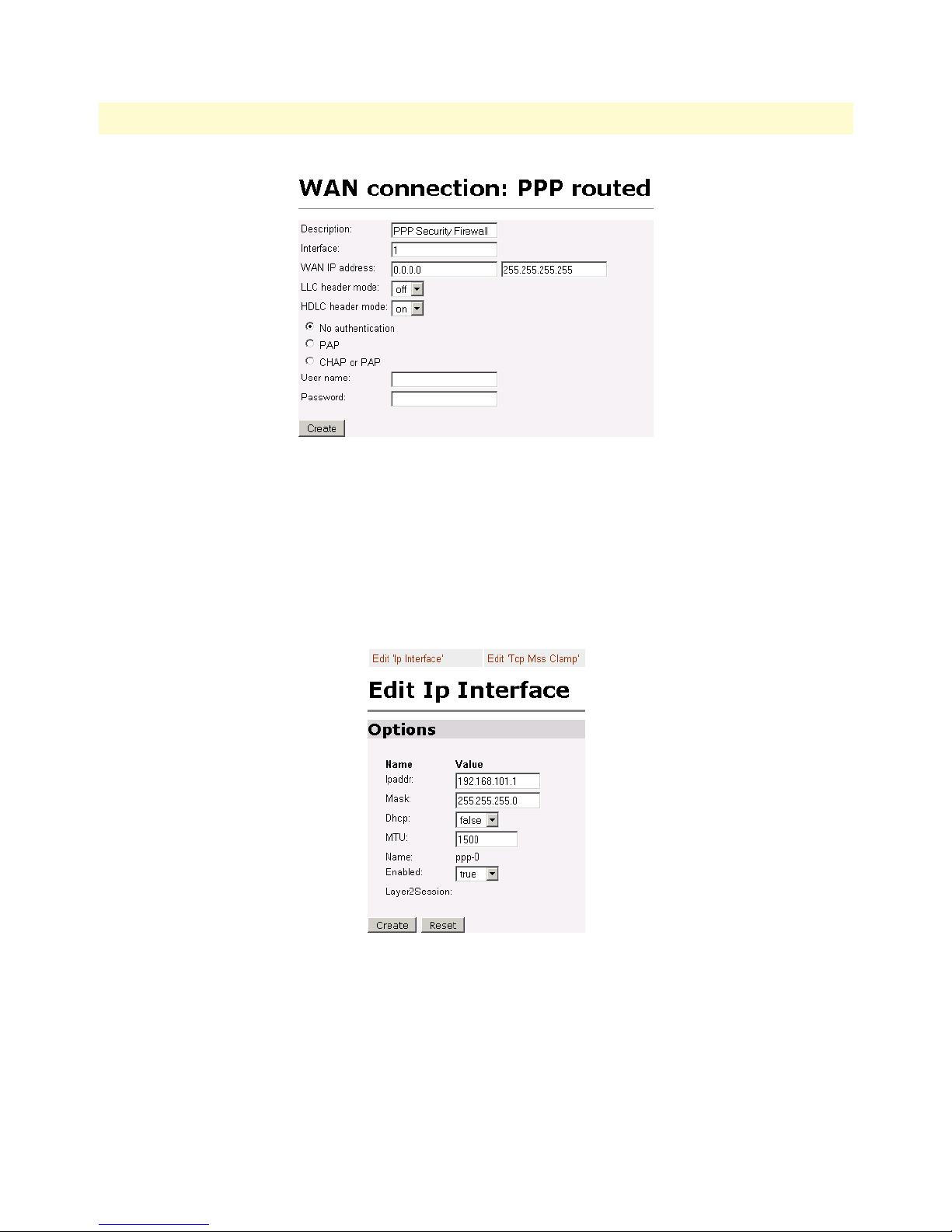
WAN Access Routers Getting Started Guide 7 • Security
Figure 43. PPP routed WAN service for Security Firewall example
6. Click on Edit in the WAN Connections webpage, and then click on the Edit ‘Ip Interface’ hyperlink.
7. In the Edit Ip Interface webpage, enter the fields as follows and click on the Create button. (See
figure 44.)
Ipaddr: 192.168.101.1
Mask: 255.255.255.0
Figure 44. IP address of PPP routed WAN service
The next step in configuring the router is to add the default gateway route. The WAN IP address of the routed
PPP WAN service at the CO site is 192.168.101.2, so this will be the gateway IP address on the Black Box.
1. Click on IP routes under Services Configuration in the Configuration Menu.
2. Click on the Create a new Ip route... hyperlink.
3. Enter 192.168.101.2 in the box adjacent to Gateway.
Configuring the router 64
Page 70
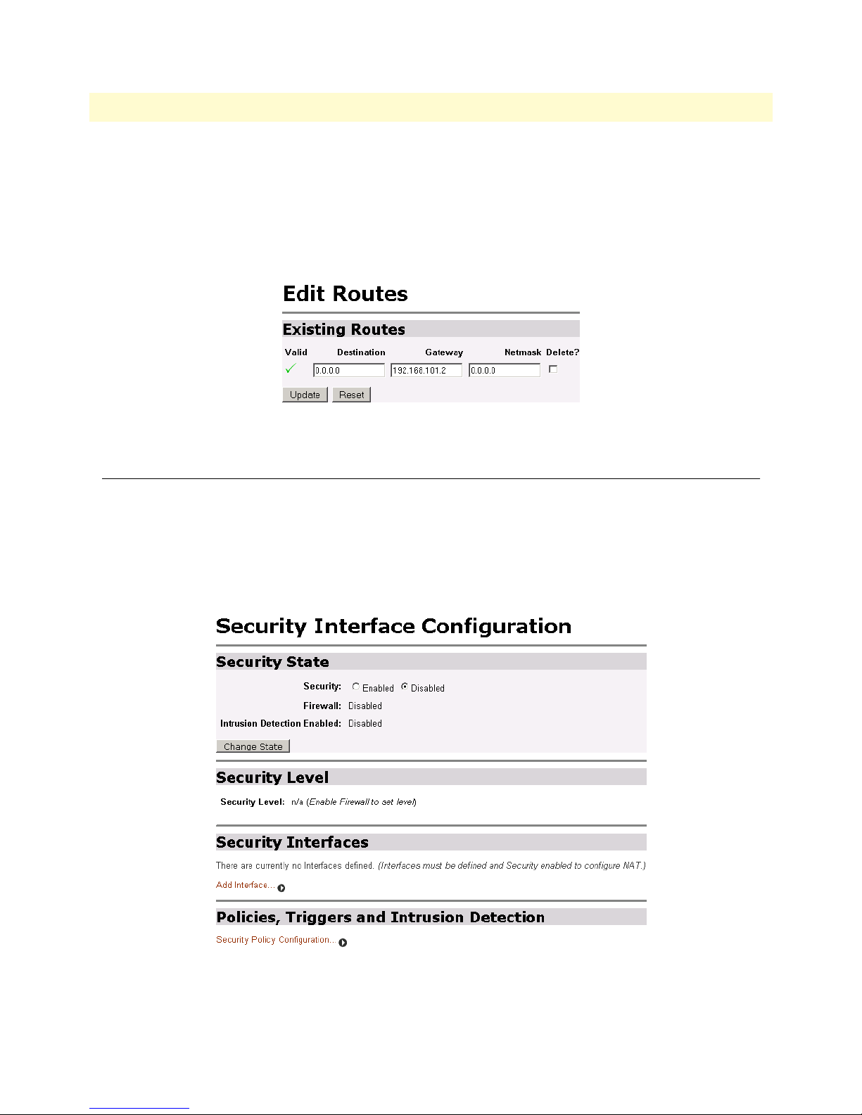
WAN Access Routers Getting Started Guide 7 • Security
4. Leave Destination and Netmask both as 0.0.0.0 because this is the gateway default route.
5. Click on the Update button.
6. Seeing the green check mark under Valid indicates the IP addresses of the WAN service and the gateway
are properly configured. (See figure 45.)
Figure 45. Valid gateway route
Configuring the security interfaces
The interfaces and routes have been configured on the WAN Access Router. The Ethernet side of the WAN
Access Router will be configured to be an internal interface and the WAN side is selected to be the external
interface since it is on “public” side of the modem connection.
1. Go to the Security Interface Configuration webpage as follows Configuration Menu > Services Configuration >
Security. (See figure 46.)
Configuring the security interfaces 65
Figure 46. Security configuration home page
Page 71
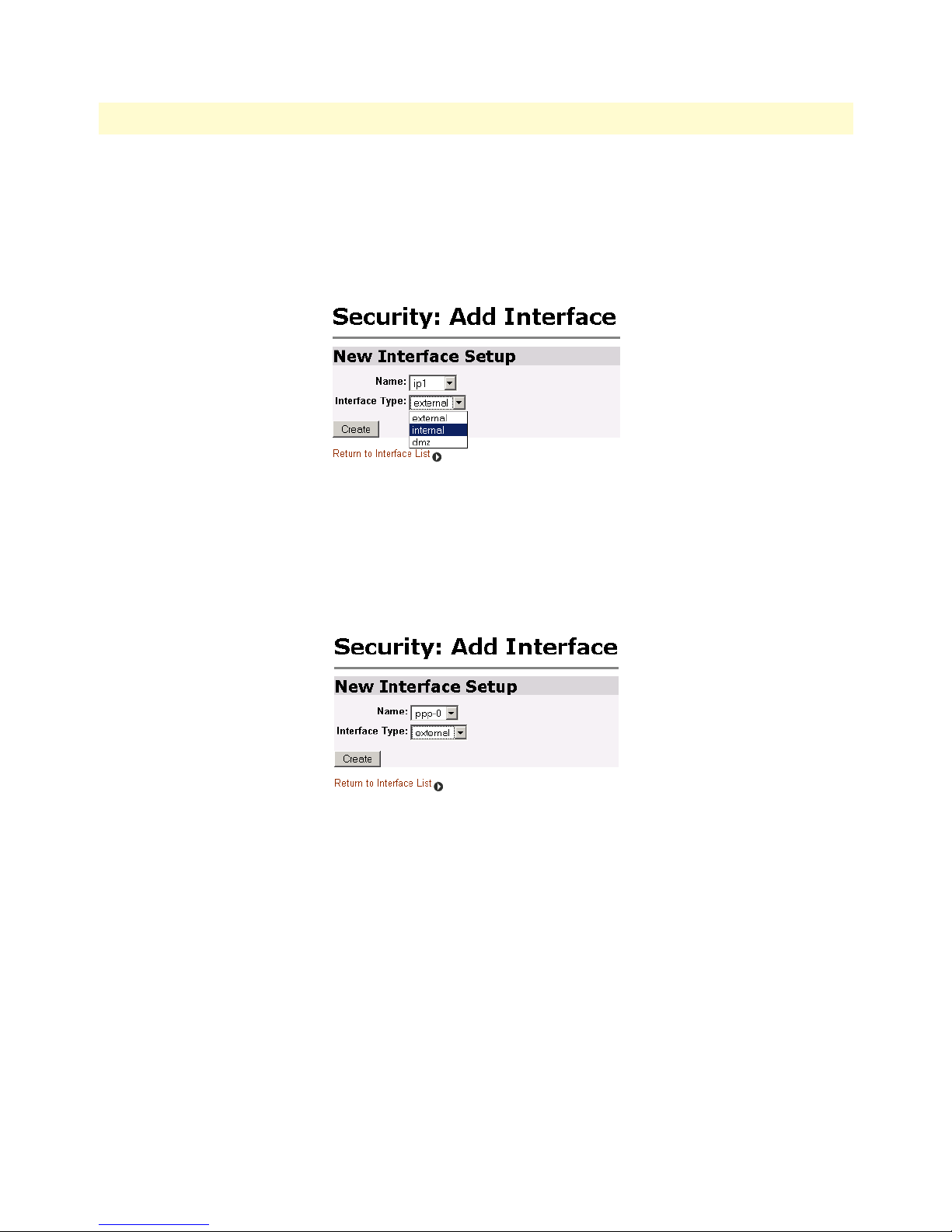
WAN Access Routers Getting Started Guide 7 • Security
2. Go to the third section (Security Interfaces) on the Security Interface Configuration webpage. Click on the
hyperlink Add interface...
3. Select ip1 beside the Name pull-down menu, and select internal beside the Interface Type pull-down menu.
Click on Create. (See figure 47.)
Figure 47. Define ‘ip1’ interface as Internal
4. Again, click on the hyperlink Add interface... to define the WAN interface as external.
5. Select ppp-0 beside the Name pull-down menu, and select external beside the Interface Type pull-down
menu. Click on Create. (See figure 48.)
Figure 48. Define ‘ppp-0’ interface as External
Configuring security policies
Continue the previous example by defining security policies. We will add only one Firewall policy, called etoi,
signifying an external-to-internal policy between the external and internal interfaces.
1. Go to the last section on the Security Interface Configuration webpage called Policies, Triggers and Intrusion
Detection. Click on the hyperlink Security Policy Configuration... (See figure 49.)
Configuring the security interfaces 66
Page 72
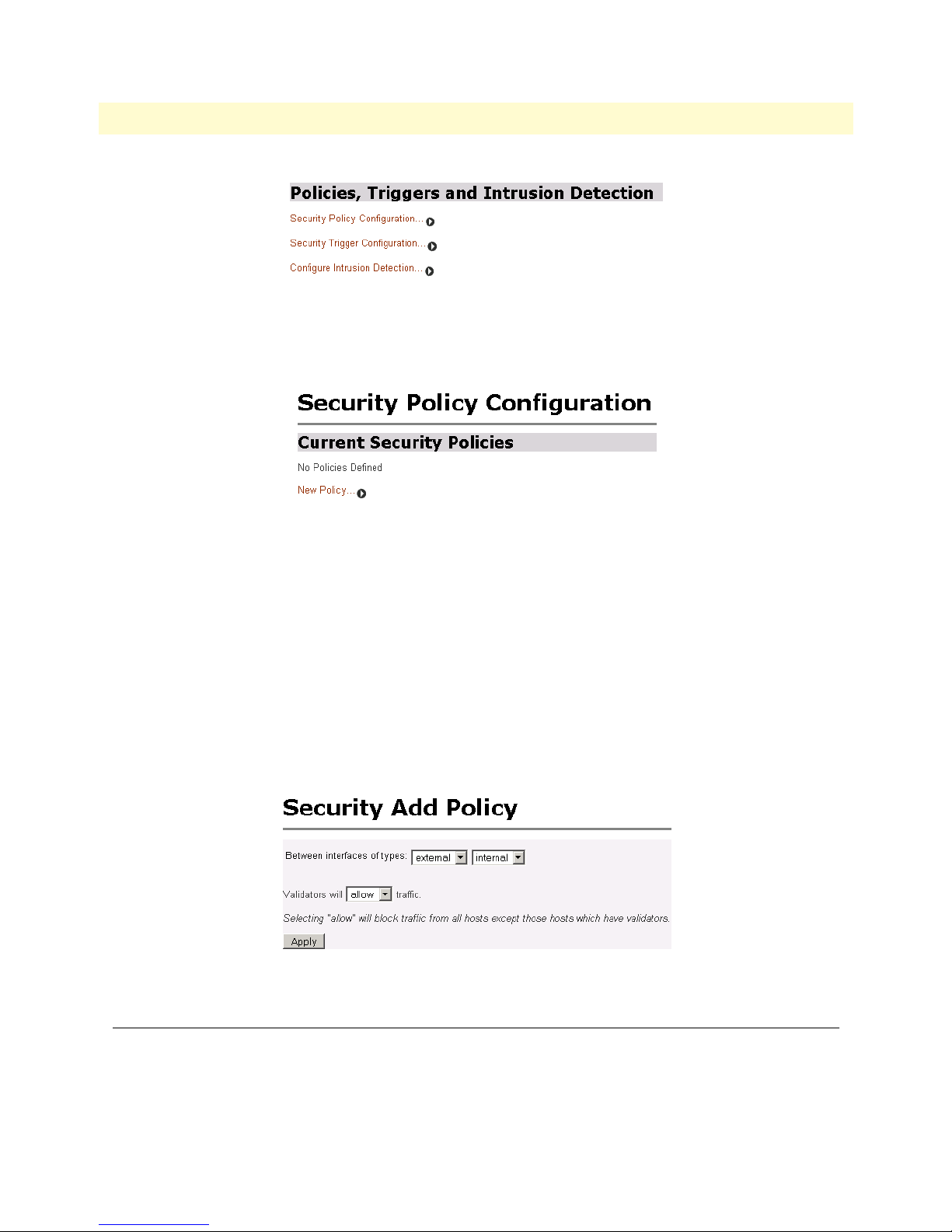
WAN Access Routers Getting Started Guide 7 • Security
Figure 49. Security Policy Configuration hyperlink
2. Click on the hyperlink New Policy... (See figure 50.)
Figure 50. New Policy link to configuration webpage
3. Select the parameters so the policy is defined as follows:
Between interfaces of types: external internal
Validators will allow traffic.
Click on Apply.
Deleting a security Policy
To delete a security policy, go to the table of Current Security Policies and click on the Delete button for the
selected security policy.
Figure 51. Deleting a Security Policy
Enabling the Firewall
At this point, both security and the firewall can be enabled and the network is secure. All the interfaces which
have been defined are protected, that is, all traffic has been blocked between the internal (ip1) and external
(ppp-0) interfaces. Only traffic which has validators is allowed to pass through, and, at this moment, there are
no validators.
Enabling the Firewall 67
Page 73

WAN Access Routers Getting Started Guide 7 • Security
1. Return to the Security page.
2. Under Security State select Enabled for Security. Click on Change State.
3. Next select Enabled for Firewall. Click on Change State.
The network is now secure. All the interfaces which have been defined are protected and all traffic is blocked
between different the different interface types. That is, all traffic is blocked between the external and
internal interfaces.
The next section describes how to configure the Firewall for allowing certain types of data transfer to occur
between the PCs on different networks.
Firewall Portfilters
Next, we configure the Firewall to permit certain types of data transfer between the PCs (in general, hosts) on
the different networks. This is done by the implementation of Firewall portfilters. Portfilters are individual
rules that determine what kind of traffic can pass between two interface types.
For the Protocol Number below, the different types are defined as:
Protocol Number Abbreviation Protocol Number Abbreviation
1 ICMP 17 UDP
2 IGMP 46 RSVP
3 GGP 47 GRE
4 IP 89 OSPFIGP
6 TCP 92 MTP
8 EGP 94 IPIP
9 IGP
This example continues to allow pings over the firewall:
1. From the Configuration Menu, > Configuration > Security > Security Policy Configuration... > Port Filters...
> Add Raw IP Filter
2. Enter 1 (for ICMP) in the Protocol Number field.
3. Set both Inbound and Outbound for Allow. (See figure 52.)
4. Click on Create.
Firewall Portfilters 68
Page 74

WAN Access Routers Getting Started Guide 7 • Security
Figure 52. Defining ICMP port filter for ping
You can now ping between the two networks
Security Triggers
Security triggers are used to allow an application to open a secondary port in order to transport data. The most
common example is FTP. This procedure sets up a trigger on the Firewall to permit an FTP session from PC A
to PC B, but not the reverse.
1. First, create an outbound-only portfilter for FTP and add it to the item0 policy.
2. Following the path given in step 1 for the ping portfilter in the previous section, click on Add TCP Filter.
3. The Port Range is entered as 21 for both Start and End.
4. Set Inbound as Block, but Outbound as Allow. (See figure 53.)
5. Click on Create.
Figure 53. Configuring TCP port filter for FTP
After configuring the FTP portfilter, you can open an ftp session from Remote to Local, however you can issue
ftp commands (e.g., login, cd, etc.). Because the trigger to permit transfer of data via FTP has not been
defined, no data can be transferred. (Data transfer occurs with the commands ls, dir, get, put commands.) The
portfilter allows an ftp control channel but does not allow the use of a secondary data channel for passing data
by ftp.
To enable the FTP data channel, add a trigger to open a secondary channel only when data is being passed.
This minimizes the number of open ports. Each open port is a security risk.
1. From the Configuration Menu, > Configuration > Security > Security Trigger Configuration... >
New Trigger.
Security Triggers 69
Page 75
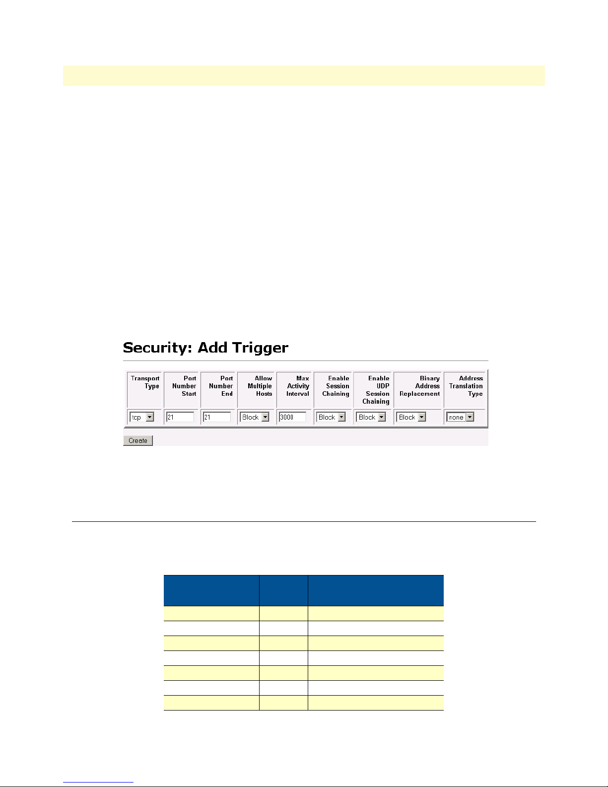
WAN Access Routers Getting Started Guide 7 • Security
2. Set the parameters as follows (See figure 54.):
– Transport Type = tcp
– Port Number Start = 21
– Port Number End = 21
– Allow Multiple Hosts = Block
– Max Activity Interval = 3000
– Enable Session Chaining = Block
– Enable UDP Session Chaining = Block
– Binary Address Replacement = Block
– Address Translation Type = none
3. Click on Create.
Figure 54. Adding trigger for FTP data transfer
You should now be able to use FTP commands to pass data between Remote and Local.
Intrusion Detection System (IDS)
The security feature in the WAN Access Router provides protection from a number of attacks. Some attacks
cause a host to be blacklisted (i.e., no traffic from that host is accepted under any circumstances) for a period of
time. Other attacks are simply logged. The subsequent table is a summary of the attacks detected.
Attack Name Protocol
Ascend Kill UDP yes
Echo/Chargen UDP no
Echo Scan UDP yes
WinNuke TCP yes
Xmas Tree Scan TCP yes
IMAP SYN/FIN Scan TCP yes
Smurf ICMP If victim protection set
Intrusion Detection System (IDS) 70
Attacking Host
Blacklisted?
Page 76

WAN Access Routers Getting Started Guide 7 • Security
Attack Name Protocol
SYN/FIN/RST Flood TCP If scanning threshold
Net Bus Scan TCP yes
Back Orifice Scan UDP yes
Attacking Host
Blacklisted?
exceeded
1. To enable IDS, click on Enabled for “Intrusion Detection Enabled” on the “Security Interface Configuration” page. Then click on Change State.
2. Click on Configure Intrusion Detection...
3. You may choose which of the parameters to configure and for which value.
– Use Blacklist: Default = 10 minutes when enabled.
If IDS has detected an intrusion an external host, access to the network is denied for ten minutes.
– Use Victim Protection: Default = Disabled.
Victim Protection. When enabled, Victim Protection protects the victim from an attempted spoofing
attack. Web spoofing allows an attacker to create a ‘shadow’ copy of the world wide web (WWW). All
access to the shadow Web goes through the attacker’s machine, so the attacker can monitor all of the victim’s activities and send false data to or from the victim’s machine. When enabled, packets destined for the
victim host of a spooking style attack are blocked.
– Victim Protection Block Duration: Default = 600 seconds
– DOS Attack Block Duration:Default = 1800 seconds (30 minutes).
A Denial of Service (DOS) attack is an attempt by an attacker to prevent legitimate users from using a service. If a DOS attack is detected, all suspicious hosts are blocked by the firewall for a set time limit
– Scan Attack Block Duration:Default = 86400 seconds
Sets the duration for blocking all suspicious hosts. The firewall detects when the system is being scanned
by a suspicious host attempting to identify any open ports.
– Victim Protection Block Duration:Default = 600 seconds (10 minutes).
Sets the duration of the block in seconds.
– Maximum TCP Open Handshaking Count:Default = 100
Sets the maximum number of unfinished TCP handshaking sessions per second that are allowed by a firewall before a SYN Flood is detected. SYN Flood is a DOS attack. When establishing normal TCP connections, three packets are exchanged: (1) A SYN (synchronize) packet is sent from the host to the network
server. (2) A SYN/ACK packet is sent from the network server to the host. (3) An Ack (acknowledge)
packet is sent from the host to the network server. If the host sends unreachable source addresses in the
SYN packet, the server sends the SYN/ACK packets to the unreachable addresses and keeps resending
them. This creates a backlog queue of unacknowledged SYN/ACK packets. Once the queue is full, the system will ignore all incoming SYN request and no legitimate TCP connections can be established.
Intrusion Detection System (IDS) 71
Page 77

WAN Access Routers Getting Started Guide 7 • Security
– Once the maximum number of unfinished TCP handshaking sessions is reached, an attempted DOS
attack is detected. The firewall blocks the suspected attacker for the time limit specified in the DOS
Attack Block Duration parameter.
– Maximum Ping Count:Default = 15
Sets the maximum number of pings per second that are allowed by the firewall before an Echo Storm is
detected. Echo Storm is a DOS attack. An attacker sends oversized ICMP datagrams to the system using
the ‘ping’ command. This can cause the system to crash, freeze, or reboot, resulting in denial of service to
legitimate users.
– Maximum ICMP Count:Default = 100
Sets the maximum number of ICMP packets per second that are allowed by the firewall before an ICMP
Flood is detected. An ICMP Flood is a DOS attack. The attacker tries to flood the network with ICMP
packets in order to prevent transmission of legitimate network traffic.
4. After selecting the chosen parameters, click on Update.
Intrusion Detection System (IDS) 72
Page 78

WAN Access Routers Getting Started Guide 7 • Security
Introduction to NAT
The basic steps for configuring NAT are:
1. Enable NAT between the internal and external interfaces of the firewall.
2. Create global addresses which will be added to the global pool of IP addresses on the WAN interface.
3. Create a reserved mapping between a global IP address and the IP address of an internal PC.
A Global Address Pool is a pool of addresses seen from the outside network. Each external interface creates a
Global Address Pool with a single address—the address assigned to that interface. For outbound sessions, an
address is picked from a pool by hashing the source IP address for a pool index and then hashing again for an
address index. For inbound sessions, it is necessary to create a reserved mapping.
A reserved mapping is used so that NAT knows where to route packets on inbound sessions. The reserved mapping will map a specific global address and port to an inside address and port. Reserved mappings can also be
used so that different inside hosts can share a global address by mapping different ports to different hosts. For
example, Host A is an FTP server and Host B is a web server. By mapping the FTP port to Host A and the
HTTP port to Host B, both insides hosts can share the same global address. Setting the protocol number to
255 (0xFF) means that the mapping will apply to all protocols. Setting the port number to 65535 (0xFFFF) for
TCP or UDP protocols means that the mapping will apply to all port numbers for that protocol.
Some applications embed address and/or port information in the payload of the packet. The most notorious of
these is FTP. For most applications, it is sufficient to create a trigger with address replacement enabled. However there are three applications for which a specific Application Level Gateway is provided: FTP, NetBIOS,
and DNS.
Enabling NAT
The configuration of NAT in this example follows on the preceding configuration completed earlier in
this chapter.
1. Go to the Security Interface Configuration page by clicking on Security under Configuration in the menu.
2. Click on Enable NAT to internal interfaces in the Security Interfaces table. NAT is now enabled between
the internal (LAN) and the external (WAN) interfaces of the firewall.
Global address pool and reserved map
1. Click on Advanced NAT Configuration... on the web page, Security Interface Configuration.
2. Click on the hyperlink Add Global Address Pool... The global IP addresses need to be created and put
into the Global Address Pool.
Introduction to NAT 73
Page 79

WAN Access Routers Getting Started Guide 7 • Security
3. Set the parameters to the following values (See figure 55.):
– Interface Type: internal
– Use Subnet Configuration: Use IP Address Range
– IP Address: 100.100.100.101
– Subnet Mask/IP Address 2: 100.100.100.102
Click on Add Global Address Pool button.
Figure 55. NAT Global Address Pool configuration
4. Next, create a reserved mapping between a global IP address from the global pool and a PC on the side of
the internal interface (ip1). In this example, 10.10.19.11.
5. Click on the hyperlink Add Reserved Mapping...
6. Set the parameters to the following values (See figure 56.):
– Global IP Address: 100.100.100.101
– Internal IP address: 10.10.19.11
– Transport Type: all
– Port Number: 65535(This port number means all port numbers for TCP or UDP protocols will
be mapped.)
7. Click on Add Reserved Mapping.
Introduction to NAT 74
Page 80
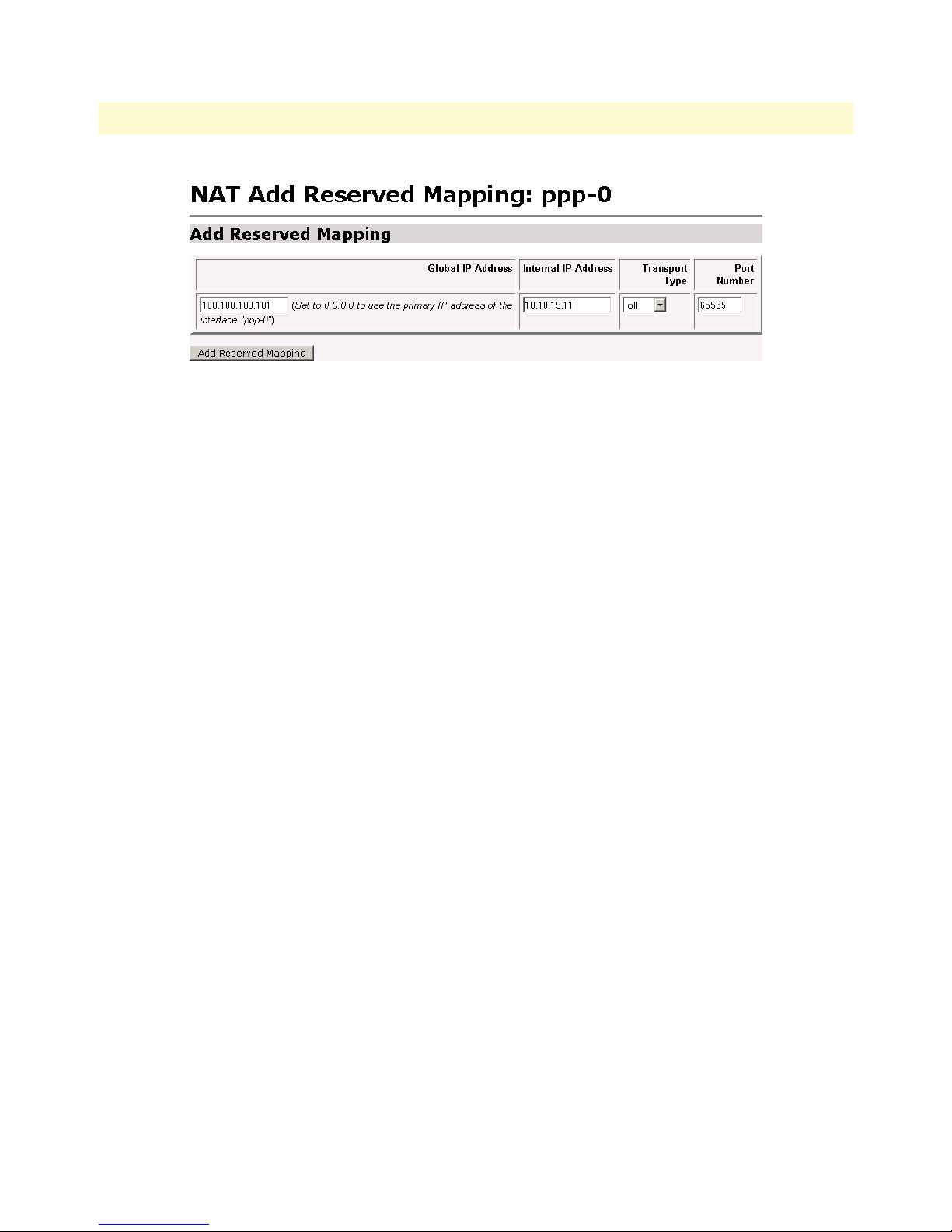
WAN Access Routers Getting Started Guide 7 • Security
Figure 56. NAT Reserved mapping configuration
The PC on the Ethernet side of the Black Box can now communicate with the ‘public’ or ‘global’ side
through NAT.
Introduction to NAT 75
Page 81

Chapter 8 DHCP and DNS configuration
Chapter contents
Introduction..........................................................................................................................................................77
Services and features normally associated with each other ................................................................................77
DHCP Server .................................................................................................................................................78
Parameters for the DHCP Server subnet ...................................................................................................80
IP Addresses to be available on this subnet ................................................................................................81
DNS server option information .................................................................................................................82
Default gateway option information ..........................................................................................................82
Additional option information ..................................................................................................................83
DHCP Relay ..................................................................................................................................................83
Configuration of the DHCP Relay ............................................................................................................83
DNS Relay ......................................................................................................................................................85
Configuring the DNS Relay ......................................................................................................................85
76
Page 82

WAN Access Routers Getting Started Guide 8 • DHCP and DNS configuration
Introduction
The routers offer a DHCP Server, DHCP Relay capability, and DNS Relay incorporated into the Black Box.
Of the two DHCP features, only one can be enabled at a time-either DHCP server or DHCP relay.
DNS relay can hold two DNS server IP addresses in memory so the DNS relay can forward DNS queries and
responses between the host user and the DNS server.
The DHCP Server will listen for DHCP client requests on a suitable IP interface. Typically this is the Ethernet
interface, named ip1 by default.
Note The Ethernet LAN port can be configured as a DHCP client to receive its IP
address from a DHCP server on the Ethernet LAN. If so configured, you
should not enable the Black Box’s DHCP server on the Ethernet interface.
DHCP Relay functions transparently between a a DHCP client and a DHCP server. The DHCP relay appears
as a DHCP server to the DHCP client’s point of view. The relay operates by forwarding all broadcast client
request to known DHCP servers. The DHCP relay listens on all available interfaces. All relay-server communication is unicast. It is important that valid routes are set up to the server and also to the client.
Services and features normally associated with each other
Table 5 on page 78 lists services that are available for configuration if you will be using DHCP Server, DHCP
Relay, or DNS Relay.
If you are configuring a feature listed in the first column (Configured Feature), you can determine which other
features either cannot be, must be, usually, can be, or are rarely used. The “Rarely used” column is listed to be
technically correct, but it is ill advised to use. The three most important columns (other than the first) are:
• Cannot be used
• Must be used
• Usually used
Use the table like this: “The feature in this column [...] with the Configured Feature (in Column 1).”
Introduction 77
Page 83

WAN Access Routers Getting Started Guide 8 • DHCP and DNS configuration
For example:
1. The feature DHCP Relay [column 2] cannot be used with DHCP Server [row 1, column 1].
2. The feature Routed [column 4] usually is used with DHCP Relay [row 2, column 1].
Table 5. Features and services matrix
The feature
Configured
Feature
DHCP Server DHCP Relay Routed,
DHCP Relay DHCP Server Routed
DNS Relay Routed,
NAT Bridged Routed DHCP Server,
DHCP Client
(WAN side)
Static IP
(WAN side)
Cannot be
used
in this
column
Must be
used
Routed
[...] with (Column 1 feature)
Usually used Can be used Rarely used
NAT
2
NAT
DHCP Server
or
DHCP Relay
DHCP Relay,
DNS Relay
Routed
Some comments on table 5:
• Routed means a ‘routed WAN service’ and Bridged means a ‘bridged WAN service.’
Bridged
Bridged
Bridged
1
3
• DHCP Server and DHCP Relay cannot be used simultaneously.
• NAT can be used only if a Routed WAN service is configured.
•1If a DHCP Server were used with a Bridged WAN service, the DHCP server would respond to IP address
requests from both interfaces, that is, the Ethernet and the WAN serial interfaces.
•2When NAT is used together with DHCP Relay, the WAN service must be routed.
•3When DHCP Relay is used with a Bridged WAN service, the DHCP server must be on the same subnet as
the clients and the Black Box.
DHCP Server
Go to the DHCP Server webpage from the Configuration Menu --> Services Configuration --> DHCP Server.
The DHCP server default is disabled. Click on the Enable button to begin the configuration process.
Introduction 78
Page 84
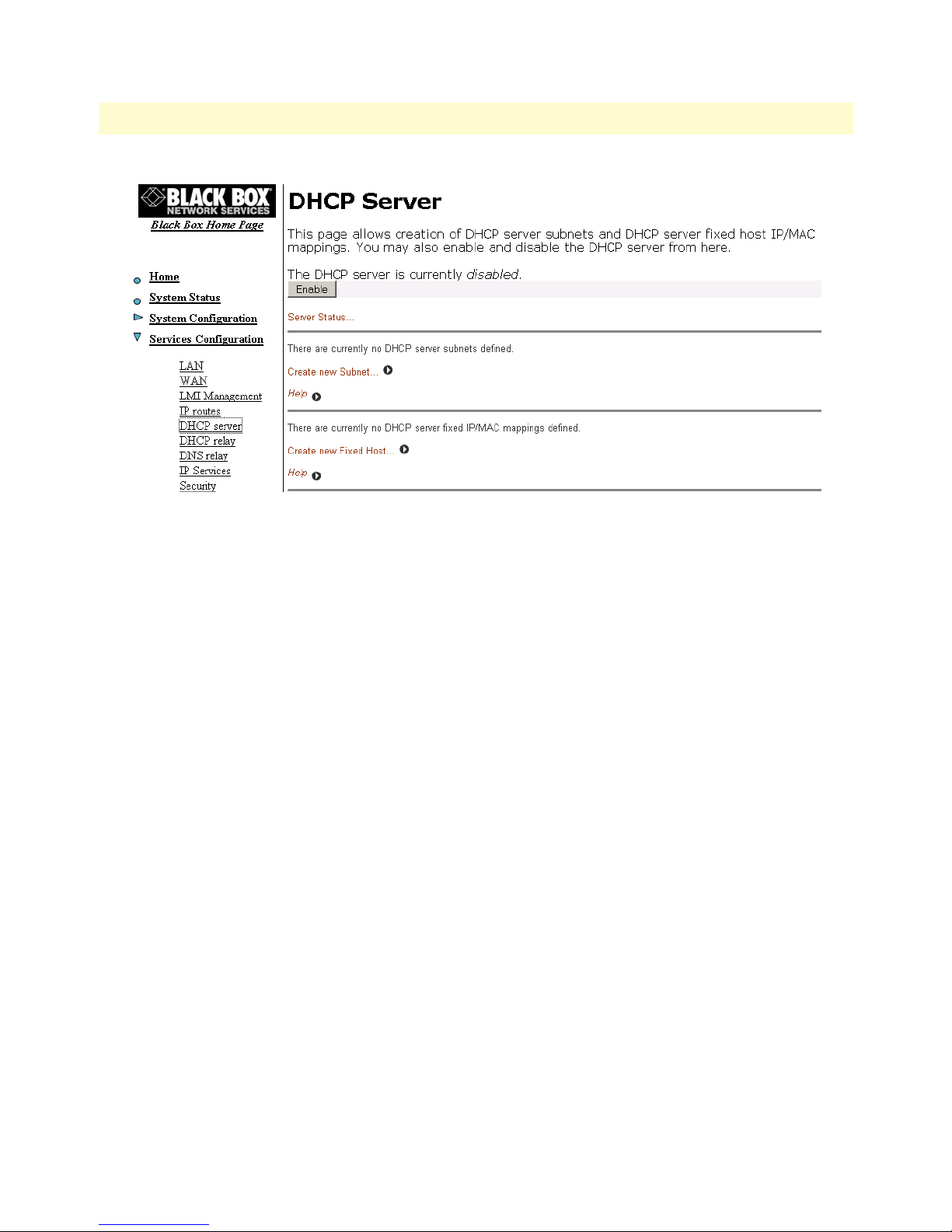
WAN Access Routers Getting Started Guide 8 • DHCP and DNS configuration
Figure 57. DHCP Server web page
The server needs to have a subnet of IP addresses which will be allocated when a DHCP client makes a request.
Define the subnet by clicking on the hyperlink Create new Subnet... The next webpage, Create new DHCP
Server subnet has four sections.
• Parameters for this subnet: defines the subnet and netmask, the origin of the subnet, maximum lease time,
and default lease time.
• IP addresses to be available on this subnet: either define the IP address range for the DHCP server IP pool,
or use the default range which is a set of 20 IP addresses.
• DNS server option information: enter the IP addresses of the primary and secondary DNS servers which
are provided to the DHCP clients.
• Default gateway option information: You may use the local host as the default gateway.
Figure 58 shows the entire configuration web page for the DHCP server.
Introduction 79
Page 85
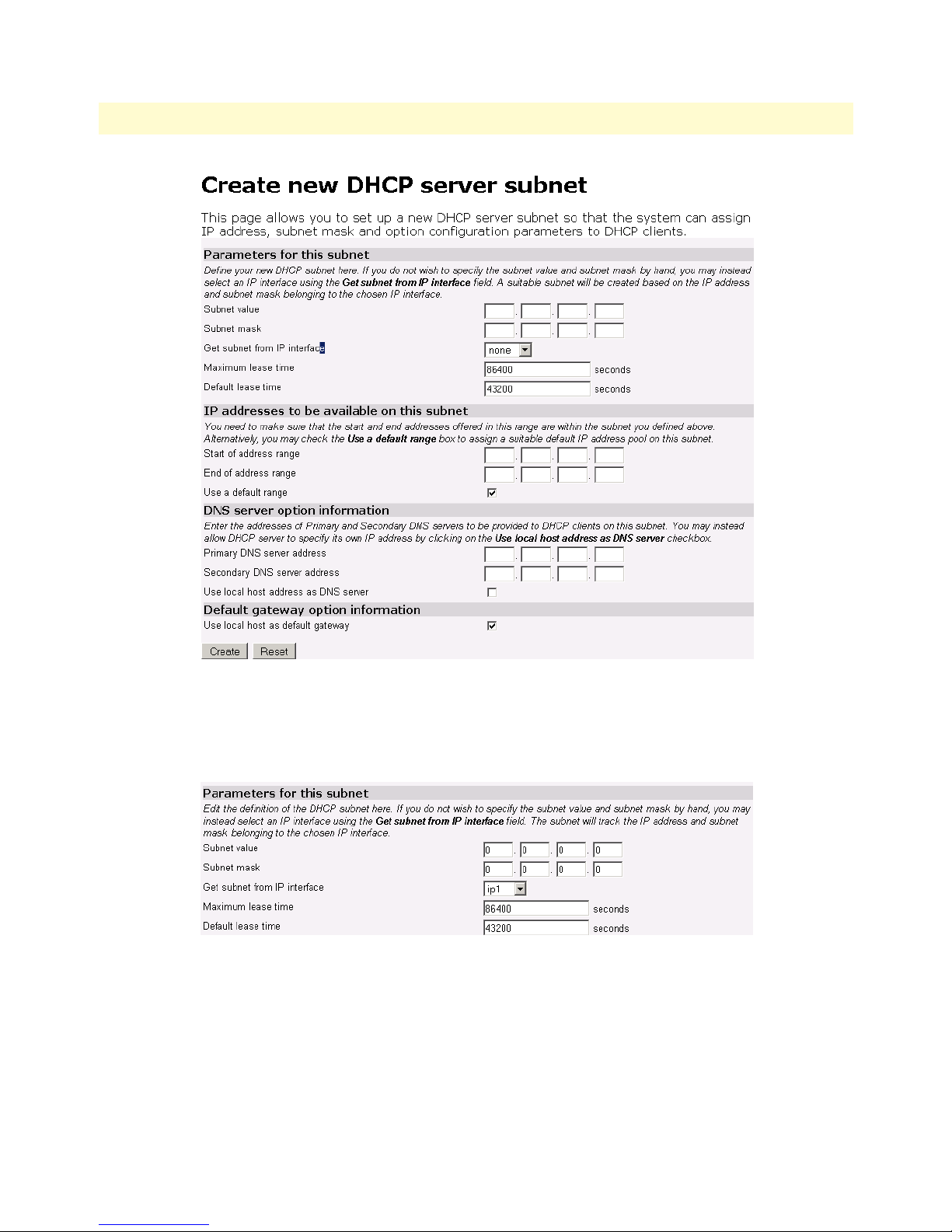
WAN Access Routers Getting Started Guide 8 • DHCP and DNS configuration
Figure 58. DHCP server configuration web page
Parameters for the DHCP Server subnet
Four parameters are in the section for defining the DHCP subnet. (See figure 59.)
Figure 59. DHCP Server subnet parameters
The first two parameters are applicable when you will define the subnet.
• Subnet value: It is necessary to enter the selected value here and the ‘Subnet mask’ if you do not ‘Get subnet
from IP interface.’ See description for the 3rd parameter.
• Subnet mask
Introduction 80
Page 86

WAN Access Routers Getting Started Guide 8 • DHCP and DNS configuration
The third parameter is
• Get subnet from IP interface: If you use this option, then you will not enter any values in the first two
parameters. Should you define another subnet and also select Get subnet from IP interface, the Black Box
uses the Get subnet from IP interface as the ruling parameter and sets Subnet value and Subnet mask appropriately, overriding your initial selection. The ip1 Ethernet interface is always one option. However there may
be a WAN interface also as an additional option. The interface is the DHCP server “listening” interface. It
listens for client requests on this interface.
The two remaining parameters are:
• Maximum lease time: the default value is 86,400 seconds.
• Default lease time: the default value is 43,200 seconds.
IP Addresses to be available on this subnet
The next section (see figure 60) has three parameters:
• Start of address range: Enter the first IP address to be available in the DHCP IP address pool.
• End of address range: Enter the last IP address to be available in the DHCP IP address pool.
Figure 60. DHCP IP address pool
• Use a default range: Checking this box will give you an IP address pool of 20 contiguous addresses. This set-
ting, when checked, overrides anything entered in the Start and End of address range.
If you have selected Get subnet from IP interface and have checked the Use a default range, the first of the twenty
IP addresses will be the next sequential address following the IP address of the IP interface. For example,
Introduction 81
Page 87

WAN Access Routers Getting Started Guide 8 • DHCP and DNS configuration
assume that the IP address of ip1 is 10.10.19.10/16. Figure 61 shows that the IP address pool ranges from
10.10.19.11 to 10.10.19.30.
Figure 61. Example based on default range of IP address pool
DNS server option information
When a client requests an IP address from a DHCP server, the server can also send the IP addresses of the primary and secondary DNS servers’ IP addresses. The Black Box can accomplish this in one of two ways, neither
really having an advantage over the other. This section of the configuration page is one method, the other is
DNS Relay to be described later in this chapter. Refer to figure 62.
Figure 62. Configuration of the DNS server IP addresses
Enter the IP addresses of the primary and secondary DNS servers. Subsequently, the client will receive these
addresses when assigned an IP address. When the client makes a DNS inquiry, it sends the request directly to
the appropriate DNS server. The WAN Access Router merely forwards the packet.
The third parameter is ‘Use local host address as DNS server’ which is the IP address of the Black Box. In this
scenario, the client considers the Black Box as a DNS server by sending all requests to the Black Box’s IP
address. The Black Box forwards the request to the DNS servers using the IP address of the actual servers. You
still need to define the IP addresses of the primary and secondary DNS servers in the section because the Black
Box needs to know in order to forward the DNS requests.
Default gateway option information
Introduction 82
Page 88

WAN Access Routers Getting Started Guide 8 • DHCP and DNS configuration
Additional option information
You may wish to provide additional information to the clients on the DHCP subnet. Click on the hyperlink
Create new DHCP option... to access the configuration webpage. The options can specify:
• A default gateway
• Domain name
• IRC server
• HTTP server
• SMTP server
• POP3 server
• NNTP server
• WINS server
• Time servers
Refer to figure 63 as an example of multiple options to be sent to the clients.
Figure 63. DHCP server optional information example
DHCP Relay
With this webpage, you can enter a list of IP addresses for DHCP servers. When a client requests an IP address,
it uses one of the DHCP addresses listed in the DHCP relay webpage. The Black Box forwards (or ‘relays’) the
request to the DHCP server.
Note Do not use the Black Box’s DHCP server if the DHCP Relay is enabled.
Configuration of the DHCP Relay
The DHCP Relay webpage has three sections. (See figure 64.)
• Enable/disable: The button in the first section enables or disables the DHCP relay on the WAN
Access Router.
• Edit DHCP server list: The IP addresses of DHCP servers can be updated, reset, or deleted from the list.
• Add new DHCP server: the IP addresses of the DHCP servers are added to the DHCP relay list in
this section.
Introduction 83
Page 89
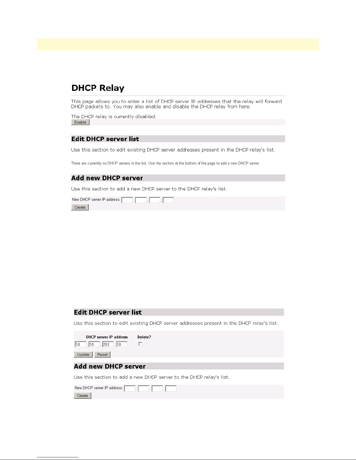
WAN Access Routers Getting Started Guide 8 • DHCP and DNS configuration
In the first section of the DHCP Relay webpage, click on the Enable button on the DHCP Relay webpage.
Figure 64. DHCP Relay webpage
In the third section of the DHCP Relay webpage, enter the IP address of a DHCP server, and click on the Create button. (See figure 65.) The IP addresses will appear in the section, Edit DHCP server list.
In the second section, you may update or delete the DHCP server IP addresses. (See figure 65.)
To update or change a DHCP server IP address, enter the desired IP address over the IP address which is no
longer valid. Click on the Update button. With this action, you do not need to delete the IP address and subsequently add a new IP address. It is one action.
To delete a DHCP server IP address, check the Delete? box for the appropriate IP address and click on the
Update button.
Introduction 84
Figure 65. DHCP Relay server list
Page 90

WAN Access Routers Getting Started Guide 8 • DHCP and DNS configuration
DNS Relay
The DNS Relay webpage contains a configurable list of DNS server IP addresses. The Black Box’s DNS Relay
forwards DNS queries from a client to a pre-defined DNS server and DNS server responses to the client.
You can configure the DNS Relay for two IP addresses. These are for access to primary and secondary
DNS servers.
Configuring the DNS Relay
Go to the DNS Relay webpage by following the hyperlink path Configuration Menu > Services Configuration >
DNS Relay. (See figure 66.)
Figure 66. Hyperlink path to the DNS Relay webpage
Introduction 85
Page 91
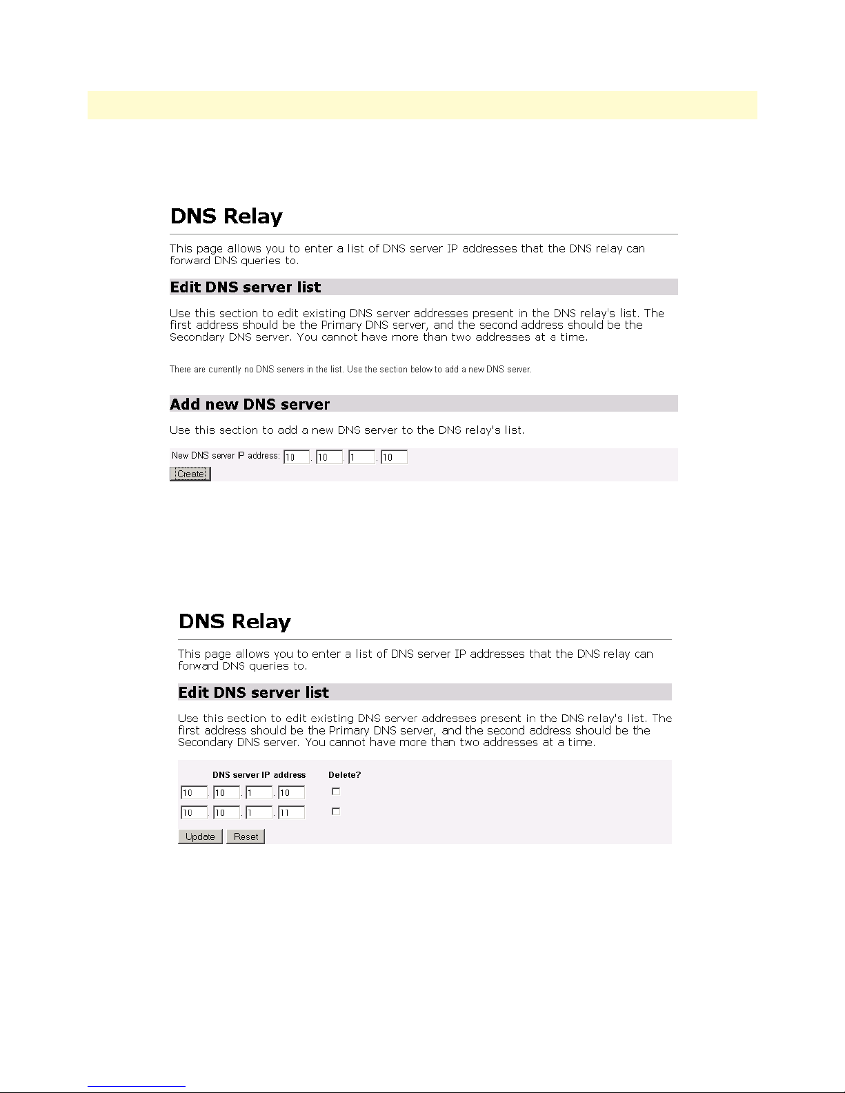
WAN Access Routers Getting Started Guide 8 • DHCP and DNS configuration
Enter the IP address of the primary DNS server (see figure 67) and click on the Create button. Similarly enter
the IP address of the secondary DNS server.
Figure 67. DNS Relay configuration webpage
You can change the IP address of the DNS servers on the DNS Relay webpage (see figure 68) by modifying the
IP address requiring the change and clicking on the Update button.
To delete the IP address of a DNS server, check the Delete? box, then click on the Update button.
Figure 68. DNS Relay - configuration completed
Introduction 86
Page 92

Chapter 9 IP Services
Chapter contents
Introduction..........................................................................................................................................................88
WEB Server...........................................................................................................................................................88
CLI Configuration ..........................................................................................................................................88
Associated Ports for the different System (IP) Services ....................................................................................89
87
Page 93

WAN Access Routers Getting Started Guide 9 • IP Services
Introduction
The following system services can be enabled or disabled:
• DNS Relay
• FTP
• TFTP
• SNMP
• WEB Server.
The importance of disabling any of these services is an issue of security. If you are not using a particular service,
it is best to disable it. By disabling it, the associated port is not active, which means it is not available to abuse
with the intent of unauthorized access.
Figure 69. System Services configuration web page
WEB Server
The System Service which must be wisely disabled is the WEB Server. After you disable the WEB Server from
the web page, you can no longer access the any of the Black Box’s web pages. The only way to enable it is
through the Command Line Interface (CLI).
CLI Configuration
After configuring a terminal emulator to access the Black Box’s serial port, there are two commands for the
enabling or disabling the WEB Server. The following command enables the WEB Server so you can access the
management web pages via a browser. Remember that by only doing this command, the change is saved only
in volatile memory. Be sure to execute the next command to save it in non-volatile memory.
→
webserver enable
→
system config save
The next command disables the WEB server.
→
webserver disable
Introduction 88
Page 94

WAN Access Routers Getting Started Guide 9 • IP Services
Associated Ports for the different System (IP) Services
This section is for information purposes only. Consult the table to identify which ports are associated with the
different System (IP) Services.
Table 6. Standard port numbers for the System Services
System (IP) Service TCP UDP
FTP 21 (control connection)
20 (data connection)
TFTP 69
SNMP 161
WEB Server 80 80
WEB Server 89
Page 95

Chapter 10 System Configuration
Chapter contents
Introduction..........................................................................................................................................................91
Detailed Description .............................................................................................................................................91
Authentication ................................................................................................................................................91
Alarm ..............................................................................................................................................................92
Remote Access ................................................................................................................................................94
Update ............................................................................................................................................................94
Save ................................................................................................................................................................95
Backup/Restore ...............................................................................................................................................95
Restart ............................................................................................................................................................96
Website Settings .............................................................................................................................................96
Error Log ........................................................................................................................................................97
SNMP Daemon ..............................................................................................................................................97
System Tools ..................................................................................................................................................98
90
Page 96
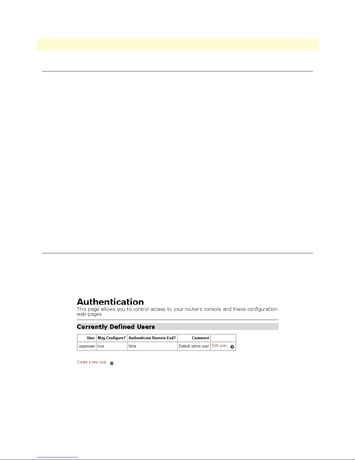
WAN Access Routers Getting Started Guide 10 • System Configuration
Introduction
The System Configuration item on the Configuration Menu opens to provide access to the following:
• Authentication: allows you to control access to the Black Box’s console and web configuration pages.
• Alarm: shows the Alarm Table and CPU Usage Settings. You can configure the alarm severity for each of the
alarms and enable/disable the Alarm Error Log.
• Remote Access: enable and set the time limit for a remote user to have access to the Black Box.
• Update: update the Black Box software from here.
• Save: to save the Black Box configuration in non-volatile memory.
• Backup/Restore: used to save the Black Box’s configuration on a PC or to load a configuration already saved
on a PC.
• Restart: to do a soft start of the Black Box or to restore the Black Box to factory defaults.
• Key: the key version is used to identify which features are installed in the Black Box.
• Website Settings: configures the refresh rate of the web pages.
• Error Log: displays the Syslog Settings and shows recent configuration errors from the Black Box.
• SNMP Daemon: to modify the SNMP parameters for the Black Box.
• Tools: provides ‘ping’ and ‘traceroute’ commands from the Black Box. Also used to clear the interface table
counters.
Detailed Description
Authentication
The Black Box manager controls access to the Black Box’s console and web pages. The default defined user is
superuser. See figure 70.
Figure 70. Authentication web page showing default superuser
The superuser is the default administrative user and is given authority to configure the Black Box, but the
default settings have disabled the ability to authenticate through a remote connection. To enable remote access
authentication, click on Edit user...
Introduction 91
Page 97
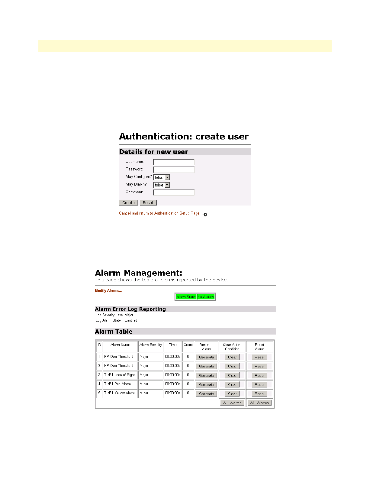
WAN Access Routers Getting Started Guide 10 • System Configuration
To add another user account, click on Create a new user... (See figure 71.) You will define the new user by
• creating a Username
• defining the Password
• give the user ability to configure the Black Box or read-only authority
• add a comment useful to the administrator
Figure 71. Creating new user
Alarm
Access the configuration and status of the alarms.
Detailed Description 92
Figure 72. Alarm Management web-page
Page 98
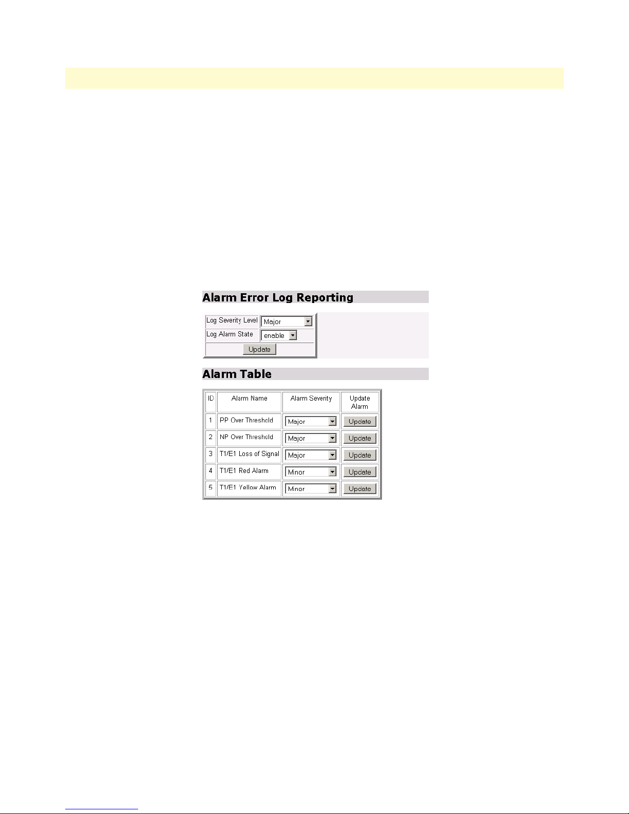
WAN Access Routers Getting Started Guide 10 • System Configuration
All Black Box routers have the ‘PP over Threshold’ and ‘NP over Threshold’ alarms. The LR120A has additional alarms for the T1/E1 WAN port. An alarm can be tested by clicking on the Generate button. Similarly,
by clicking on the Clear button, the alarm is cleared, that is, turned off, however the Time and Count parameters remain. Only by clicking on the Reset button can you clear the alarm and reset the Time and Count
parameters. The parameter definitions are:
• Alarm Severity: there are five categories of severity-Critical, Major, Minor, Informational, and Ignore.
• Time: the time that the last alarm occurred.
• Count: the number of instances the alarm has occurred.
To configure the severity of each alarm and to configure the Alarm Error Log, click on Modify Alarms... to
reach the webpage. (See figure 73.)
Figure 73. Alarm & Alarm Error Log configuration
The Alarm Error Log can be enabled or disabled. The severity level of the Alarm Log can also be configured.
Similarly each alarm can be set for its own severity level.
Detailed Description 93
Page 99
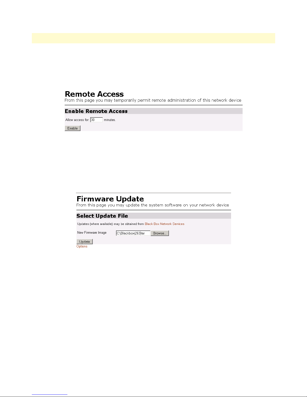
WAN Access Routers Getting Started Guide 10 • System Configuration
Remote Access
The Black Box can be accessed via Telnet, known as Remote Access (see figure 74). The length of access over a
remote connection is set on this webpage. If set for zero (0), no user can access the Black Box remotely. However if a user is authorized for access, then the time is the limit before the remote access session is closed.
Figure 74. Remote Access (Telnet) access limit
Update
To upgrade the Black Box to another software version, select the software image by clicking on the Browse button. The software is a ‘.tar’ file. (See figure 75.) After selected, the software is downloaded to the Black Box.
Wait until the upload has completed. The best way to monitor when the Black Box reboots is to view the process from the RS-232 console port.
Clicking on Options provides for selecting ‘Firmware Update Configuration.’ If enabled, the Black Box will
prevent updating with incorrect software.
Detailed Description 94
Figure 75. Updating software
Page 100
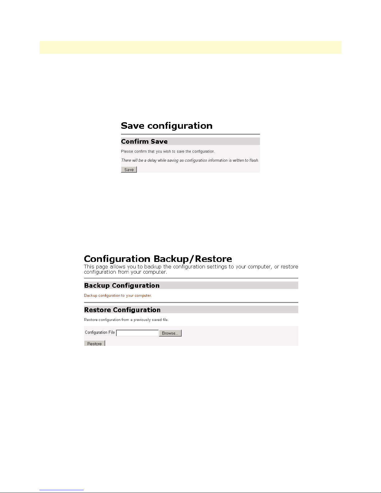
WAN Access Routers Getting Started Guide 10 • System Configuration
Save
To save configuration changes to non-volatile memory, it is essential to click on the Save button on this
webpage. (See figure 76.) If you do not do this, all configuration changes are stored only in volatile memory,
meaning that if the Black Box is restarted, all configuration changes are lost. Click on the Save button and wait
until seeing the message Saved information model to im.conf.
Figure 76. Save configuration changes in non-volatile memory
Backup/Restore
You may save or use previously saved configurations from this webpage. Should you want to save a specific
application configuration from the Black Box, click on Backup configuration to your computer.
To reload a previously saved configuration file (.icf ), browse and select the file from your computer. Click on
the Restore button to load into the Black Box. (See figure 77.)
Figure 77. Saving or reloading previously saved configuration files
Detailed Description 95
 Loading...