

Page 1

May 2004
LR1102A-T1/E1
LR1104A-T1/E1
LR1112A-T1/E1
LR1114A-T1/E1
Black Box LR11xx Series Router Configurations
CUSTOMER
SUPPORT
INFORMATION
Order toll-free in the U.S. 24 hours, 7 A.M. Monday to midnight Friday: 877-877-BBOX
FREE technical support, 24 hours a day, 7 days a week: Call 724-746-5500 or fax 724-746-0746
Mail order: Black Box Corporation, 1000 Park Drive, Lawrence, PA 15055-1018
Web site: www.blackbox.com • E-mail: info@blackbox.com
Page 2

Black Box LR11xx Series Router Configurations Guide
FEDERAL COMMUNICATIONS COMMISSION
AND
CANADIAN DEPARTMENT OF COMMUNICATIONS
RADIO FREQUENCY INTERFERENCE STATEMENTS
This equipment generates, uses, and can radiate radio frequency energy and
if not installed and used properly, that is, in strict accordance with the manufacturer’s instructions, may cause interference to radio communication. It
has been tested and found to comply with the limits for a Class A computing
device in accordance with the specifications in Subpart B of Part 15 of FCC
rules, which are designed to provide reasonable protection against such
interference when the equipme nt is operated in a commercial environment .
Operation of this equipment in a residential area is likely to cause interference, in which case the user at his own expense will be required to take
whatever measures may be necessary to correct the interference.
Changes or modifications not expressly approved by the party responsible
for compliance could void the user’s authority to operate the equip ment.
This digital apparatus does not exceed the Class A limits for radio noise
emission from digital apparatus set out in the Radio Interference Regulation
of the Canadian Depar tm e nt of Com m un i c at ion s .
Le présent appareil numérique n’émet pas de bruits radioélectriqu es dépassant les limites applicables aux appareils numériques de la classe A prescrites dans le Règlement sur le brouillage radioélectrique publié par le
ministère des Communications du Canada.
2
Page 3

Normas Oficiales Mexicanas (NOM)
Electrical Safety Statement
INSTRUCCIONES DE SEGURIDAD
1. Todas las instrucciones de seguridad y operación deberán ser leídas antes de que
el aparato eléctrico sea operado.
2. Las instrucciones de seguridad y operación deberán ser guardadas para referencia
futura.
3. Todas las adve rtencias en el aparato eléctrico y en sus instrucciones de operación
deben ser respetadas.
4. Todas las instrucciones de operación y uso deben ser seguidas.
5. El aparato eléctrico no deberá ser usado cerca del agua—por ejemplo, cerca de la
tina de baño, lavabo, sótano mojado o cerca de una alberca, e tc.
6. El aparato eléctrico debe ser usado únic amente con carritos o pedestales que sean
recomendados por el f a bricante.
7. El aparato eléctrico debe ser mo ntado a la pared o al techo sólo como sea
recomendado por el fabricante.
8. Servicio—El usuario no deb e intentar dar servic io al equipo eléctric o más allá a lo
descrito en las instrucciones de operació n. Todo otro servicio deberá ser referido a
personal de servicio calificado.
9. El aparato eléctrico debe ser situado de tal manera que su posición no interfiera su
uso. La colocación del aparato eléctrico sobre una cama, sofá, alfombra o superficie similar puede bloquea la ventilación, no se debe colocar en libreros o gabinetes que impida n el flujo de aire por los or ificios de ventilación.
10. El equipo eléctrico deber ser situado fuera del alcance de fuentes de calor como
radiadores, registros de calor, estufas u otros aparatos (incluyendo amplificadores) que producen calor.
11. El aparato eléctrico deberá ser connectado a una fuente de pode r sól o del tipo
descrito en el instructivo de operación, o como se indique en el aparato.
12. Precaución debe ser tomada de tal manera que la tierra fisica y la polarización del
equipo no sea eliminada.
13. Los cables de la fuente de poder deben ser guiados de tal manera que no sean pisados ni pellizcados por objetos colocados sobre o contra ellos, poniendo particular
atención a los contactos y receptáculos donde salen del aparato.
14. El equipo eléctrico debe ser limpiado únicamente de acuerdo a las recomendaciones del fabricante.
15. En caso de existir, una antena externa deberá ser localizada lejos de las lineas de
energia.
3
Page 4

Black Box LR11xx Series Router Configurations Guide
16. El cable de corriente deberá ser desconectado del cuando el equipo no sea usado
por un largo periodo de tiempo.
17. Cuidado debe ser tomado de tal manera que objectos liquidos no sean derramados
sobre la cubierta u orificios de ventilación.
18. Servicio por pers onal calificado de berá ser provisto cuando:
A: El cable de poder o el contacto ha sido dañado; o
B: Objectos han caído o líquido ha sido derramado dentro del aparato ; o
C: El aparato ha sido expuesto a la llu via ; o
D: El aparato parece no operar normalmente o muestra un cambio en su desem-
peño; o
E: El aparato ha sido tira do o su cubierta ha sido dañada.
4
Page 5

Contents
DHCP RELAY........................................................................................13
DHCP Relay ......................................................................................13
Feature Overview ...........................................................................13
Functionality ..................................................................................13
BOOTP Requests ............................. ...... ........................................13
BOOTP Replies ..............................................................................14
Using DHCP Relay with NAT ................................ .......................14
Command Line Interface ...............................................................14
Enabling DHCP Relay ...................................................................14
Disabling DHCP Relay ............................... ...... .............................15
Configuring the Gateway Address field when NAT is enabled .....15
Displaying DHCP Configuration ...................................................15
Displaying Statistics ......................................................................15
DHCP Limitations .........................................................................16
Contents
C
ONFIGURING INTERNET GROUP MANAGEMENT PROTOCOL ...........17
IGMP Configuration ..........................................................................17
IGMP Commands ..........................................................................18
IGMP Configuration Examples .....................................................1 8
Example 1 .......................................................................................18
Example 2 .......................................................................................18
Example 3 .......................................................................................18
Example 4 .......................................................................................18
Example 5 .......................................................................................19
Example 6 .......................................................................................19
Example 7 .......................................................................................19
Example 8 .......................................................................................19
Example 9 .......................................................................................19
Example 10 .....................................................................................19
Example 11 .....................................................................................19
Example 12 .....................................................................................19
Example 13 .....................................................................................19
F
ILTERING IP TRAFFIC.........................................................................21
IP Packet Filter Lists ...................................... ...... .............................21
Example1 .......................................................................................21
Configure the Black Box LR1104A. ..............................................21
Example 2 ......................................................................................22
Configure the Black Box LR1104A ...............................................22
Example 3 ......................................................................................22
Configure the Black Box LR1104A ...............................................22
C
ONFIGURING SECURITY......................................................................2 3
IPSec Configurations .........................................................................23
Example 1: Managing the Black Box LR1104A Securely Over
an IPSec Tunnel .................................................................................24
Example 2: Single Proposal: Tunnel Mode Between Two Black
5
Page 6

Black Box LR11xx Series Router Configurations Guide
Box Security Gateways .....................................................................28
Example 3: Multiple IPSec Proposals: Tunnel Mode Between
Two Black Box Security Gateways .................................................. 33
Example 4: IPSec remote access to corporate LAN using user
group method .................................................................................... 35
Example 5: IPSec remote access to corporate LAN using mode
configuration method ........................................................................ 40
IPS
EC SPECIFICATIONS ........................................................................ 47
IPSec Appendix ..................................................................................47
Black Box IKE and IPSec Defaults .............................................. 48
IKE Defaults .................................................................................. 48
IPSec Defaults ...............................................................................48
F
ORWARDING IP TRAFFIC.................................................................... 51
IP Multiplexing ..................... ..... ................................................... ....51
Packet Forwarding Modes ............................. ................................ 51
Proxy ARP and Packet Forwarding .............................................. 51
Addressing in IP Multiplexing Networks ..................................... 52
Single Subnet ................................................................................ 53
Split Subnet ...................................................................................53
Secondary Addressing – POP Only .............................................. 54
Secondary Addressing – 30 Bit ..................................................... 54
Secondary Addressing – 29 Bit ..................................................... 55
Pros and Cons of Different IP Addressing Schemes ..................... 55
Routing Considerations for IP Multiplexing ................................. 55
IP M
ULTIPLEXING HDLC CONFIGURATIONS .................................... 57
Connecting a Black Box Router to a Router/CSU via HDLC .......... 57
Configure the Black Box LR1104A at Site 2 ................................58
ULTIPLEXING PPP AND MLPPP CONFIGURATIONS.................. 59
IP M
Configuring Multiple PPP and MLPPP Bundles .............................. 59
Configure the Black Box LR1104A at the Main Site ...................61
ONFIGURING PPP, MLPPP, AND HDLC........................................... 63
C
Layer Two Configurations: PPP, MLPPP, and HDLC .....................63
MLPPP Configuration ................................................................... 64
Configure the Black Box LR1114A System at Site 1 ...................64
PPP and MLPPP Configuration .................................................... 64
Configure the Black Box LR1104A System at the Main Site ....... 64
HDLC Configuration ....................................................................64
Configure the Black Box LR1104A System at the Main Site ....... 64
C
ONFIGURING FIREWALLS................................................................... 65
Firewalls ............................................................................................ 65
Firewall Configuration Examples ..................................................... 66
Basic Firewall Configuration ........................................................ 66
Stopping DoS Attacks ...................................................................73
Packet Reassembly ........................................................................ 74
NAT Configurations ......................................................................... 74
6
Page 7

NAT Configuration Examples ...........................................................74
Dynamic NAT (many to many) .....................................................75
Static NAT (one to one) ................................................................. 7 6
Port Address Translation (Many to one) ........................................77
M
ULTIPATH MULTICAST CONFIGURATIONS .......................................79
Multipath Multicast ...........................................................................79
Multipath Commands ........................................................................80
Multipath Examples .......................................................................80
C
ONFIGURING NAT...............................................................................81
Network Address Translation ............................................................81
Dynamic NAT ................................................................................81
Static NAT .....................................................................................81
Configuration for Figure 1 .............................................................82
Configuration for Figure 2 .............................................................83
Reverse NAT ................................................................................. 8 3
Configuration for Figure 3 .............................................................84
Contents
NAT C
ONFIGURATION EXAMPLES.......................................................85
NAT Configurations ..........................................................................85
NAT Configuration Examples ...........................................................85
Dynamic NAT (many to many) .....................................................85
Static NAT (one to one) ................................................................. 8 7
Port Address Translation (Many to one) ........................................88
Method:1 – Specifying NAT address with the policy command ...88
Method:2 – Attaching nat pool to the policy .................................88
R
EMOTE ACCESS VPNS ........................................................................89
Secure Remote Access Using IPSec VPN ........................................89
Access Methods .................................................................................89
Remote Access: User Group ..........................................................89
Remote Access: Mode Configuration ............................................90
Configuration Examples ....................................................................90
IPSec Remote Access User Group Method – Single Proposal,
Pre-shared Key Authentication .........................................................90
IPSec Remote Access Mode Configuration Group Method .............92
N
ETWORKING WITH ROUTING INFORMATION PROTOCOL.................95
Routing Information Protocol ...........................................................95
Configuring RIP for Ethernet 0 and WAN 1 Interfaces ................95
Displaying RIP Configuration .......................................................9 5
Displaying All Configured RIP Interfaces .....................................95
C
ONFIGURING STATIC ROUTES............................................................97
Static Routing Configuration .............................................................97
Configure the Router at Site “A” ...................................................98
Configure the Router at site “B” ....................................................98
C
ONFIGURING OPEN SHORTEST PATH FIRST ROUTING.....................99
OSPF Routing Protocol .....................................................................99
7
Page 8

Black Box LR11xx Series Router Configurations Guide
Configuring the host name ............................................................ 99
Configuring interface ethernet 0 ...................................................99
Configuring interface bundle Dallas ............................................. 99
Configuring ospf ........................................................................... 100
Configuring ospf interface parameters .......................................... 100
Displaying neighbors ....................................................................100
Displaying ospf routes ................................................................... 100
Displaying IP routes ...................................................................... 100
C
ONFIGURING GENERIC ROUTING ENCAPSULATION......................... 101
Configuring GRE .............................................................................. 101
Installing Licenses ............................................................................ 101
GRE Configuration Examples .......................................................... 102
Configuring Site to Site Tunnel ....................................................103
Configuring GRE Site to Site with IPSec .........................................105
Configuring GRE Site to Site with IPSec and OSPF ........................ 106
C
ONFIGURING OSPF AND FRAME RELAY..........................................107
OSPF - Frame Relay ......................................................................... 107
Configuring the host name ............................................................ 108
Configuring interface ethernet 0 ...................................................108
Configuring interface bundle Dallas ............................................. 108
Configuring OSPF .........................................................................108
Configuring interface Dallas parameters ...................................... 108
Configuring interface ethernet 0 parameters ................................. 108
Displaying OSPF parameters ........................................................ 108
C
ONFIGURING PROTOCOL INDEPENDENT MULT ICASTING ROUTING 109
PIM Configuration ....................................................... ..................... 109
PIM Commands ................................. ...........................................109
PIM Configuration Examples .................................. ...... ..... .......... 112
MTRACE CONFIGURATION....................................................................117
Multicast Traceroute Facility ............................................................ 117
mtrace Command .......................................................................... 117
Restrictions .................................................................................... 117
mtrace Example .............................................................................118
C
ONFIGURING QUALITY OF SERVICE ROUTING................................. 119
Configuring QoS ...............................................................................119
Features ......................................................................................... 119
Definitions ..................................................................................... 120
Classification Types ......................................................................120
Create bundle AppTest .................................................................. 121
Create traffic classes ...................................................................... 121
Assign classification types ............................................................. 121
VLAN Identifiers .......................................................................... 121
Create bundle VLANtest ............................................................... 122
Create traffic classes and assign classifications ............................. 122
Bulk Statistics ................................................................................ 122
Configuring bulk statistics ............................................................. 123
8
Page 9

VIRTUAL LAN TAGGING....................................................................... 1 25
Managing Traffic with VLAN Tagging ............................................125
Reston configuration: Black Box LR1104A ..................................126
Configure interface bundle balt1 ....................................................126
Configure interface balt1 pvc 100 ..................................................126
Configure interface bundle dc1 ......................................................126
Configure interface ethernet 0 ....................................................... .126
Configure ip routing .......................................................................127
DC configuration: Black Box LR1114A .......................................127
Configure interface ethernet 0 ....................................................... .127
Configure interface bundle mip .....................................................127
Configure ip routing .......................................................................127
M
ANAGING REDUNDANT CONNECTIONS..............................................129
Trunk Group/Failover ........................................................................129
Configuration Details .....................................................................129
Configure the Black Box LR1114A for Failover Operation ..........130
Contents
WAN I
NTERFACE CONFIGURATIONS ...................................................131
T1 Interface Configuration ................................................................131
Module Configuration ...................................................................131
T1 ...................................................................................................131
Bundle Configuration ....................................................................131
Fractional T1 ..................................................................................131
V
IRTUAL LAN FORWARDING...............................................................133
Managing VLAN Traffic ...................................................................133
POP configuration: Black Box LR1104A .....................................135
Configure mlppp bundle interface .................................................135
Configure interface ethernet 0 ....................................................... .135
Configure in-band vlan forwarding table .......................................135
Configure rate limiting for vlans ....................................................135
Bldg1 configuration: Black Box LR1114A ...................................135
Configure interface bundle uplink ................................................. 1 36
Configure inband VLAN forwarding table ....................................136
Configure rate limiting for VLANs ................................................ 1 36
Configure SNMP ............................................................................136
M
UTLILINK FRAME RELAY ..................................................................137
Multilink Frame Relay FRF.15 and FRF.16 .....................................137
Features ..........................................................................................137
# Configure Ethernet interface .......................................................138
# Configure CVC1 .........................................................................138
# Congfigure CVC2 .......................................................................138
# Configure CVC3 .........................................................................138
#Configure AVC ............................................................................. 1 38
C
ONFIGURING FRAME RELAY AND MULTILINK FRAME RELAY ....... 1 39
Layer Two Configurations FR and MFR ..........................................139
FR Configuration ...........................................................................140
Configure the HSSI Bundle at Site 1 .............................................140
Configure the Clear Channel Bundle on the LR1104A .................141
MFR Configuration ................................................. .......................141
9
Page 10

Black Box LR11xx Series Router Configurations Guide
Configure the LR1104A LR1104A at Site 1 ................................. 141
Configure the LR1104A ................................................................ 141
Configure the LR1104A LR1114A at Site 2 ................................. 142
Configure the LR1104A ................................................................ 142
10
Page 11

1
r
DHCP R
ELAY
1.1DHCP Relay
This application describes the functionality of the DHCP relay feature and includes CLI command examples.
1.1.1 Feature Overview
Black Box DHCP relay feature eliminates the need for a DHCP server on every LAN, because DHCP requests can be
relayed to a single remote DHCP server. Black Box’s implementation of DHCP relay is based on RFC 1532.
BOOTP/DHCP messages are relayed (vs. forwarded) between the server and client.
Figure 1 DHCP Relay Overview
LAN
Tasman 1400
DHCP Relay Agent
LAN
LAN
LR1114A
Tasman 1400
DHCP Relay Agent
Tasman 1400
DHCP Relay Agent
WAN
Tasman 6300
LR1104A
DHCP Serve
1.1.2 Functionality
The DHCP relay feature uses BOOTP requests and replies to negotiate packet delivery between the DHCP client and server.
1.1.2.1 BOOTP Requests
BOOTP requests are messages from client to server. Request messages include DHCP DISCOVER, DHCP REQUEST,
DHCP RELEASE, etc. The relay agent modifies the packet header by adding relay information to the DHCP gateway address
(giaddr) field. The server replies to the gateway address specified in the packet’s giaddr field.
Page 12
Black Box LR11xx Series Router Configurations Guide
r
r
r
1
N
Figure 2 BOOTP Requests
Broadcast BOOTREQUEST
Tasman 1400
DHCP Client DHCP Serve
DHCP Relay Agent
Unicast BOOTREQUEST
1.1.2.2 BOOTP Replies
BOOTP replies are messages from the server to the client. Reply messages include DHCP OFFER, DHCP ACK, DHCP
NAK, etc. The relay agent looks up the MAC address and either sends the packet to the client or broadcasts it on the
LAN.
Figure 3 BOOTP Replies
Unicast/Broadcast
BOOTREPLY
Tasman 1400
DHCP Client DHCP Serve
DHCP Relay Agent
Unicast
BOOTREPLY
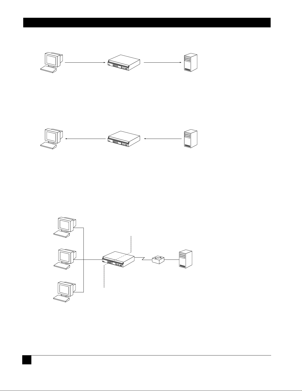
1.1.3 Using DHCP Relay with NAT
When NAT is enabled, the DHCP server may discard packets because the giaddr does not match the source of the packet.
Additionally, it may not know how to route the packet back to the client. See Figure 4. The solution is that the gateway
address (giaddr) field needs to have IP add ress 192. 168.2 0.1 (in this ex ample). The DHCP serv er config urati on shoul d be
able to give 10.1.1.x addresses for packets from 192.168.20.1. However, there may be a limitation that the DHCP server
does not allow configuration using IP addresses from a different subnet, although this is mentioned in the RFC.
Figure 4 A Typical Scenario
Network Address Translation
PRIVATE PUBLIC
192.168.20.1
Tasman 1400
DHCP Relay Agent
Router
DHCP Serve
0.1.1.x
etwork
DHCP Client
10.1.1.1
DHCP Client
DHCP Client
1.1.4 Command Line Interface
The following are examples of command strings relevant to DHCP relay:
1.1.4.1 Enabling DHCP Relay
14
Page 13

DHCP Relay
Blackbox> configure terminal
Blackbox/configure> interface ethernet 0
Blackbox/configure/interface/ethernet 0> dhcp server_address 20.1.1.1
1.1.4.2 Disabling DHCP Relay
Blackbox/configure/interface/ethernet 0> no dhcp server_address 20.1.1.1
1.1.4.3 Configuring the Gateway Address field when NAT is enabled
Blackbox/configure/interface/ethernet 0> dhcp gateway_address 192.168.20.1
1.1.5 Displaying DHCP Configuration
The following screen captures show the displayed results of issuing show commands relevant to DHCP relay, with and without
gateway addresses configur ed.
Figure 5 show dhcp_relay Command
> show dhcp_relay
DHCP RELAY CONFIGURATION
--------------------------Ethernet 0: Disabled
Ethernet 1: Enabled: DHCP Server 10.1.1.1
Figure 6 show dhcp_relay Command
> show dhcp_relay
DHCP RELAY CONFIGURATION
--------------------------Ethernet 0: Disabled
Ethernet 1: Enabled: DHCP Server 10.1.1.1 (Gateway
Address: 192.168.20.1)
1.1.6 Displaying Statistics
15
Page 14

Black Box LR11xx Series Router Configurations Guide
Figure 7 Displaying Ethernet Interface Statistics
> show interface ethernet 1
ethernet 1
ipaddr 192.168.120.1
netmask 255.255.255.0
description status down, operationally down
configured auto
speed mode actual
speed 100
mode half_duplex
mtu 1500
ethernet1 (unit number 1)
Type: ETHERNET (802.3)
Flags: (0x807c203) UP, MULTICAST-ROUTE
Internet Address: 192.168.120.1
Internet Netmask: 255.255.255.0
Internet Broadcast: 192.168.120.255
Maximum Transfer Unit: 1500 bytes
Mac Address: 00:00:23:00:60:01
port counters since last boot/clear
Bytes Rx 0 Bytes Tx 0
Packets Rx 0 Packets Tx 0
Runts Rx 0 Collisions 0
Babbels Rx 0 Late Collisions 0
Err Packets Rx 0 Up/Down States (Phys) 0
Up/Down States (Admin) 2
port counters for the last five minutes
Bytes Rx 0 Bytes Tx 0
Packets Rx 0 Packets Tx 0
Runts Rx 0 Collisions 0
Babbels Rx 0 Late Collisions 0
1.1.7 DHCP Limitations
There are limitations when using DHCP relay on a Black Box system. Only one DHCP server can be specified per interface. DHCP
can be enabled only on Ethernet interfaces (not on bundles). And last, DHCP can be enabled in IP routing (static and dynamic) mode,
but not in IP Mux mode.
16
Page 15

2
C
ONFIGURING INTERNET
M
ANAGEMENT
2.1IGMP Configuration
Internet Group Management Protocol (IGMP) is enabled on hosts and routers that want to receive multicast traffic.
IGMP informs locally-attached routers of their multicast group memberships. Hosts inform routers of the groups of
which they are members by multicasting IGMP Group Membership Reports. When multicast routers listen for these
reports, they can exchange group membership information with other multicast routers. This reporting system allows
distribution trees to be formed to deliver multicast datagrams. The original version of IGMP was defined in RFC 1112,
Host Extensions for IP Multicasting. Extensions to IGMP, known as IGMP version 2.
IGMPv2 improves performance and supports the following message types:
IGMP Query: IGMP Query is sent by the router to know which groups have members on the attached network.
IGMP Reports: IGMP reports are sent as a response to the query by hosts to announce their group membership.
Reports can be sent “unsolicited” when the hosts come up.
IGMP Leaves: IGMP Leaves are sent by the host when it relinquishes membership of a group.
The latest extension to the IGMP standard is Version 3, which includes interoperability with version 2 and version 1
hosts, also provides support for source filtering. Source filtering enables a multicast receiver host to signal to a router
which groups it wants to receive multicast traffic from, and from which source(s) this traffic is expected. This
membership information enables the router to forward traffic only from those sources from which receivers requested
the traffic.
IGMPv3 supports applications that explicitly signal sources from which they want to receive traffic. With IGMPv3,
receivers signal membership to a multicast host group in the following two modes:
INCLUDE mode: In this mode, the receiver announces membership to a host group and provides a list of IP
addresses (the INCLUDE list) from which it wants to receive traffic.
EXCLUDE mode: In this mode, the receiver announces membership to a host group and provides a list of IP
addresses (the EXCLUDE list) from which it does not want to receive traffic. This indicates that the host wants
to receive traffic only from other sources whose IP addresses are not listed in the EXCLUDE list. To receive
traffic from all sources, like in the case o f the In ternet S t an dard Multicast (ISM) s erv ice mod el, a h os t exp resses
EXCLUDE mode membership with an empty EXCLUDE list.
IGMPv3 is used by the hosts to express their desire to be a part of the source-specific multicast (SSM) which is an
emerging standard used by routers to direct multicast traffic to the host only if its is from a specific source.
P
G
ROUP
ROTOCOL
Page 16

Black Box LR11xx Series Router Configurations Guide
2.1.1 IGMP Commands
The IGMP commands are:
ip igmp
ignore-v1-messages
ignore-v2-messages
last-member-query-count
last-member-query-interval
query-interval
query-response-interval
require-router-alert
robustness
send-router-alert
startup-query-count
startup-query-interval
group filter
version
debug ip igmp
debug ip igmp state
debug ip igmp normal
debug ip igmp packet query
debug ip igmp packet report
debug ip igmp packet leave
show ip igmp groups
show ip igmp interface
clear ip igmp groups
2.1.2 IGMP Configuration Examples
Use the examples shown in this section to use IGMP in multicast configurations.
2.1.2.1 Exampl e 1
The following example enables IGMP.
Blackbox/configure> ip igmp
2.1.2.2 Exampl e 2
With the command line still in Interface Configuration Mode, the following example disables IGMP.
Blackbox/configure> no ip igmp
2.1.2.3 Exampl e 3
In the following example, the ignor e-v 1-messag es command is used to disable processing of IGMPv1 messages on
interface ethernet 0.
Blackbox/configure/ip/igmp/interface ethernet0> ignore-v1-messages
Blackbox/configure/ip/igmp/interface ethernet0> exit 3
Blackbox/configure>
2.1.2.4 Exampl e 4
In the following example, the ignore-v2-messages command disables processing of IGMPv1 messages on
interface ethernet 0.
18
Page 17

IGMP Configuration
Blackbox/configure/ip/igmp/interface ethernet0> ip igmp ignore-v2-messages
Blackbox/configure/ip/igmp/interface ethernet0> exit 3
Blackbox/configure>
2.1.2.5 Example 5
The following example configures the Last Member Query Count to be 4 on ethernet 0.
Blackbox/configure/ip/igmp/interface ethernet0> last-member-query-count 4
2.1.2.6 Example 6
In the following example for interface ethernet 0, the Robustness is configured to be 4. The Last Member Query count is
configured to be 5.
Blackbox/configure/ip/igmp/interface ethernet0> robustness 4
Blackbox/configure/ip/igmp/interface ethernet0> last-member-query-count 5
Blackbox/configure/ip/igmp/interface ethernet0> exit 3
Blackbox/configure>
2.1.2.7 Example 7
The following example configures ethernet 0 with the default Last Member Query Interval of 2000 milliseconds (20 seconds).
Blackbox/configure/ip/igmp/interface ethernet0> last-member-query-interval 2000
2.1.2.8 Example 8
The following example configures ethernet 0 with the default Query Interval to be 200 seconds.
Blackbox/configure/ip/igmp/interface ethernet0> query-interval 200
2.1.2.9 Example 9
The following example configures the default Query Response Interval to be 10 seconds (or 100 deciseconds) for ethernet 0.
Blackbox/configure/ip/igmp/interface ethernet0> query-response-time 100
2.1.2.10Example 10
The following example turns require-router-alert on for interface ethernet 0.
Blackbox/configure/ip/igmp/interface ethernet0> require-router-alert
2.1.2.11Example 11
The following example configures the default Robustness to be 3 for interface ethernet 0.
Blackbox/configure/ip/igmp/interface ethernet0> ip igmp robustness 3
2.1.2.12Example 12
The following example turns the send-router-alert option off for interface ethernet 1.
Blackbox/configure/ip/igmp/interface ethernet1> no send-router-alert
2.1.2.13Example 13
The following example configures IGMP version 2 to run on interface ethernet 0.
Blackbox/configure/ip/igmp/interface ethernet0> version 2
Blackbox/configure/ip/igmp/interface ethernet0> exit 3
Blackbox/configure>
19
Page 18

Black Box LR11xx Series Router Configurations Guide
20
Page 19

3w
F
ILTERING
3.1IP Packet Filter Lists
Black Box systems can be configured for IP traffic filtering capabilities. IP traffic filtering allows creation of rule sets
that selectively block TCP/IP packets on a specified interface. Filters are applied independently to all interfaces:
Ethernet, serial, or WAN, as well as independently to interface direction: IN (packets coming in to the Black Box
system) or OUT (packets going out of the Black Box system).
IP packet filtering capability can be used to restrict access to the Black Box system from untrusted, external networks or
from specific, internal networks. An example would be a filter that prohibits external users from establishing Telnet
sessions to the Black Box system, and allows only specific internal users Telnet access to the system.
At the end of every rule list is an implied “deny all traffic” statement. Therefore, all packets not explicitly permitted
by filtering rules, are denied. This effectively means that once you enter a “deny” statement in your filter list, you
are implicitly denying all packets from crossing the interface. Therefore, it is important that each filter list contain at
least one “permit” statement.
The order in which you enter the filtering rules is important. As the Black Box system is evaluating each packet, the
Black Box OS tests the packet against each rule statement sequentially. After a match is found, no more rule
statements are checked. For example, if you create a rule statement that explicitly permits all traffic, all traffic is
passed since no further rules are checked.
The Black Box OS permits easy re-ordering of filter commands through filter_list insert and delete commands.
IP T
RAFFIC
3.1.1 Example1
Consider a Black Box connected via a bundle “WAN1” (wan IP address 200.1.1.1) to an ISP, with Ethernet 0 (IP
address 222.199.19.3) connected to the internal network. The network administrator wants to completely block Telnet
access to the Black Box from all external networks as well as from all internal networks except 222.199.19.0/28. All
other TCP/IP traffic, such as FTP, Ping, and HTTP, is to flow unrestricted through the Black Box system.
3.1.1.1 Configu re the Black Box LR1104A.
Blackbox> configure term
Blackbox/configure> ip
Blackbox/configure/ip> filter_list filtera (gives the list a name)
Blackbox/configure/ip/filter_list> add deny tcp any 200.1.1.1 dport =23
Blackbox/configure/ip/filter_list> add permit tcp 222.199.19.0/28 222.199.19.3 dport =23
Blackbox/configure/ip/filter_list> add deny tcp any 222.199.19.3 dport =23
Blackbox/configure/ip/filter_list> add permit ip any any
Blackbox/configure/ip/filter_list> exit
Page 20

Black Box LR11xx Series Router Configurations Guide
Blackbox/configure/ip> apply_filter ether0 filtera in
Blackbox/configure/ip> apply_filter WAN1 filtera in
Blackbox/configure/ip> exit
Blackbox/configure> exit
Blackbox> save local
3.1.2 Exa mple 2
Consider the same network addressing as in example 1. The network administrator has a slightly different
requirement - he wishes to permit FTP sessions from all networks to the internal FTP server (222.199.19.12), deny
FTP sessions to all other addresses, and permit all other traffic to flow through the Black Box unit.
3.1.2.1 Config ure the Black Box LR1104A
Blackbox> configure terminal
Blackbox/configure> ip
Blackbox/configure/ip> filter_list filterb (gives the list a name)
Blackbox/configure/ip/filter_list> add permit tcp any 222.199.19.12 dport =21
Blackbox/configure/ip/filter_list> add deny tcp any 222.199.19.0 dport =21
Blackbox/configure/ip/filter_list> add permit ip any any
Blackbox/configure/ip/filter_list> exit
Blackbox/configure/ip> apply_filter WAN1 filterb in
Blackbox/configure/ip> exit
Blackbox/configure> exit
Blackbox> save local
3.1.3 Exa mple 3
Example 3 focuses on a filter list where the network administrator is specifically denying all traffic from a specific
external network (197.100.200.0/24) access through the Black Box unit.
3.1.3.1 Config ure the Black Box LR1104A
Blackbox> configure terminal
Blackbox/configure> ip
Blackbox/configure/ip> filter_list filterc (gives the list a name)
Blackbox/configure/ip/filter_list> add deny ip 197.100.200.0/24 any
Blackbox/configure/ip/filter_list> add permit ip any any
Blackbox/configure/ip/filter_list> exit
Blackbox/configure/ip> apply_filter WAN1 filterc in
Blackbox/configure/ip> exit
Blackbox/configure> exit
Blackbox> save local
22
Page 21

C
ONFIGURING
S
ECURITY
4.1IPSec Configurations
This guide provides information and examples on how to configure IPSec.
There are three licenses that control access to the features:
Basic VPN Management (vpn_mgmt)—allows users to manage a remote Black Box router.
Firewall (firewall)—allows users to manage the firewall features. Also includes Basic VPN Management.
Advanced VPN and firewall (vpn_plus_firewall)—Allo ws users to manage remote LANs. Also includes
Basic VPN and Firewall licenses.
To see the licenses available in this release, enter:
4
Blackbox/configure> system licenses ?
NAME
licenses - Configure feature upgrade licenses
SYNTAX
licenses license_type <cr>
DESCRIPTION
license_type -- Specifies the type of feature upgrade license
The parameter may have any of the following values:
enable_1_port -- Enable 1 port
enable_2_ports-- Enable 2 ports
enable_3_ports-- Enable 3 ports
enable_4_ports-- Enable 4 ports
BGP4 -- BGP4 routing
vpn_mgmt -- Enable VPN Mgmt License
firewall -- Enable Firewall and VPN Mgmt License
vpn_plus_firewall-- Enable Advance VPN and Firewall License
To install the advanced VPN and firewall license and use all the security features available in this release, enter:
Page 22

Black Box LR11xx Series Router Configurations Guide
N
1
4
Blackbox/configure> system licenses vpn_plus_firewall
Enter Security Upgrade License key: 024f3bc296b4ea7265
4.2 Example 1: Managing the Black Box LR1104A Securely Over an IPSec Tunnel
The following example demonstrates how to manage a Black Box router through an IP security tunnel. Steps are
presented for configuring the Black Box1 and Black Box2 routers to assist any host on the LAN side of Black
Box-2 to manage the Black Box1 router through the IP security tunnel.
The security requirements are as follows:
Phase 1: 3DES with SHA1
Phase 2: IPSec ESP with AES and HMAC-SHA1
Figure 8 T unnel Mode Between Two Black Box Security Gateways - Multiple Proposals
TRUSTED
etwork
0.0.1.0/24
Black Box 1
Tasman1
172.16.0.1
IPSec ESP
UNTRUSTED
172.16.0.2
Tasman2
Black Box 2
TRUSTED
Network
10.0.2.0/2
Step 1: Configure a WAN bundle of network type untrusted
Black Box1/configure> interface bundle wan1
message: Configuring new bundle
Black Box1/configure/interface/bundle wan1> link t1 1
Black Box1/configure/interface/bundle wan1> encapsulation ppp
Black Box1/configure/interface/bundle wan1> ip address 172.16.0.1 24
Black Box1/configure/interface/bundle wan1> crypto untrusted
Black Box1/configure/interface/bundle wan1> exit
Step 2: Configure the Ethernet interface with trusted network type
Black Box1/configure> interface ethernet 0
message: Configuring existing Ethernet interface
Black Box1/configure interface/ethernet 0> ip address 10.0.1.1 24
Black Box1/configure/interface/ethernet 0> crypto trusted
Black Box1/configure/interface/ethernet 0> exit
Step 3: Display the crypto interfaces
24
Page 23

Example 1: Managing the Black
Blackbox> show crypto interfaces
Interface Network
Name Type
--------- ------wan1 Untrusted
ethernet0 trusted
Blackbox>
Step 4: Add route to peer LAN
Black Box1/configure> ip route 10.0.2.0 24 wan1
Step 5: Configure IKE to the peer gateway
Black Box1/configure> crypto ike policy Black Box2 172.16.0.2
Black Box1/configure/crypto/ike/policy Black Box2 172.16.0.2> local-address 172.16.0.1
message: Default proposal created with priority1-des-sha1-pre_shared-g1.
message: Key String has to be configured by the user.
Black Box1/configure/crypto/ike/policy Black Box2 172.16.0.2> key secretkey
Black Box1/configure/crypto/ike/policy Black Box2 172.16.0.2> proposal 1
Black Box1/configure/crypto/ike/policy Black Box2 172.16.0.2/proposal 1> encryption-algorithm
3des-cbc
Black Box1/configure/crypto/ike/policy Black Box2 172.16.0.2/proposal 1> exit
Black Box1/configure/crypto/ike/policy Black Box2 172.16.0.2> exit
Step 6: Display IKE policies
Blackbox> show crypto ike policy all
Policy Peer Mode Transform
------ ---- ---- --------Black Box 172.14.0.2 Main P1 pre-g1-3des-sha
Blackbox>
Step 7: Display IKE policies in detail
Displays the encryption algorithm, hash algorithm, authentication mode, and other details of the IKE policies.
Step 8: Configure the IPSec tunnel to the remote host
Black Box1/configure/crypto> ipsec policy Black Box2 172.16.0.2
Black Box1/configure/crypto/ipsec/policy Black Box2 172.16.0.2> match address 172.16.0.1 32
10.0.2.0 24
message: Default proposal created with priority1-esp-3des-sha1-tunnel and activated.
Black Box1/configure/crypto/ipsec/policy Black Box2 172.16.0.2> proposal 1
Black Box1/configure/crypto/ipsec/policy Black Box2 172.16.0.2/proposal 1>
encryption-algorithm aes128-cbc
Black Box1/configure/crypto/ipsec/policy Black Box2 172.16.0.2/proposal 1> exit
Black Box1/configure/crypto/ipsec/policy Black Box2 172.16.0.2> exit
Step 9: Display IPSec policies
Displays the policy just added.
Step 10: Display IPSec policies in detail
Shows the details of the IPSec policies.
25
Page 24

Black Box LR11xx Series Router Configurations Guide
Step 10.1: Configure firewall policies to allow IKE negotiation through untrusted interface (applicable onl y if firewall license is also
enabled)
Black Box1/configure> firewall internet
Black Box1/configure/firewall internet> policy 1000 in service ike self
Black Box1/configure/firewall internet/policy 1000 in> exit
Black Box1/configure/firewall internet> exit
Step 10.2: Configure firewall policies to allow desired services through untrusted interface to manage the router (applicable only if
firewall license is also enabled)
Black Box1/configure> firewall internet
Black Box1/configure/firewall internet> policy 1001 in service snmp self
Black Box1/configure/firewall internet/policy 1001 in> exit
Black Box1/configure/firewall internet> policy 1002 in service telnet self
Black Box1/configure/firewall internet/policy 1002 in> exit
Black Box1/configure/firewall internet> policy 1003 in protocol icmp self
Black Box1/configure/firewall internet/policy 1003 in> exit
Black Box1/configure/firewall internet> exit
Step 10.3: Display firewall policies in the internet map (applicable only if firewall license is enabled)
Black Box1> show firewall policy internet
Advanced: S - Self Traffic, F - Ftp-Filter, H - Http-Filter,
R - Rpc-Filter, N - Nat-Ip/Nat-Pool, L - Logging,
E - Policy Enabled, M - Smtp-Filter
Pri Dir Source Addr Destination Addr Sport Dport Proto Action Advanced
--- --- ----------- ---------------- ----------------- ------ -------1000 in any any ike PERMIT SE
1001 in any any snmp PERMIT SE
1002 in any any telnet PERMIT SE
1003 in any any any any icmp PERMIT SE
1024 out any any any any any PERMIT SE
Step 10.4: Display firewall policies in the internet map in detail (applicable only if firewall license is enabled)
26
Page 25

Black Box1> show firewall policy internet detail
Policy with Priority 1000 is enabled, Direction is inbound
Action permit, Traffic is self
Logging is disable
Source Address is any, Dest Address is any
Source Port is any, Service Name is ike
Schedule is disabled, Ftp-Filter is disabled
Smtp-Filter is disabled, Http-Filter is disabled
Rpc-Filter is disabled, Nat is disabled
Bytes In 0, Bytes Out 0
Policy with Priority 1001 is enabled, Direction is inbound
Action permit, Traffic is self
Logging is disable
Source Address is any, Dest Address is any
Source Port is any, Service Name is snmp
Schedule is disabled, Ftp-Filter is disabled
Smtp-Filter is disabled, Http-Filter is disabled
Rpc-Filter is disabled, Nat is disabled
Bytes In 0, Bytes Out 0
Example 1: Managing the Black
Policy with Priority 1002 is enabled, Direction is inbound
Action permit, Traffic is self
Logging is disable
Source Address is any, Dest Address is any
Source Port is any, Service Name is telnet
Schedule is disabled, Ftp-Filter is disabled
Smtp-Filter is disabled, Http-Filter is disabled
Rpc-Filter is disabled, Nat is disabled
Bytes In 0, Bytes Out 0
Policy with Priority 1003 is enabled, Direction is inbound
Action permit, Traffic is self
Logging is disable
Source Address is any, Dest Address is any
Source Port is any, Dest Port is any, Protocol is icmp
Schedule is disabled, Ftp-Filter is disabled
Smtp-Filter is disabled, Http-Filter is disabled
Rpc-Filter is disabled, Nat is disabled
Bytes In 0, Bytes Out 0
Policy with Priority 1024 is enabled, Direction is outbound
Action permit, Traffic is self
Logging is disable
Source Address is any, Dest Address is any
Source Port is any, Dest Port is any, any
Schedule is disabled, Ftp-Filter is disabled
Smtp-Filter is disabled, Http-Filter is disabled
Rpc-Filter is disabled, Nat is disabled
Bytes In 0, Bytes Out 0
Step 11 : Enable SNMP on the Black Box1 router
27
Page 26

Black Box LR11xx Series Router Configurations Guide
N
1
4
Black Box1/configure/crypto/> exit
Black Box1/configure> snmp
Black Box1/configure/snmp> community public rw
Black Box1/configure/snmp> exit
Step 12: Display SNMP communities
Blackbox>show snmp communities
Community = public, privileges=rw
Blackbox>
Step 13: Repeat step s 1 - 10 with sui table modif icatio ns on Black Bo x2 prior t o managing Black Box1 fr om Bla ck Box2’ s LAN
side
Step 14: Test the IPSec tunnel for managing the Black Box1 router from a host on Black Box2’s LAN.
Step 15: When the SNMP manager starts managing Black Box1 from Black Box2’s LAN, display the IKE and IPSec SA
tables using:
show crypto ike sa all
show crypto ike sa all detail
show crypto ipsec sa all
show crypto ipsec sa all detail
4.3 Example 2: Single Proposal: Tunnel Mode Between Two Black Box Security Gateways
The following example demonstrates how to form an IP security tunnel to join two private networks: 10.0.1.0/24 and
10.0.2.0/24. The security requirements are as follows:
Phase 1: 3DES with SHA1
Phase 2: IPSec ESP with AES (256-bit) and HMAC-SHA1
Figure 9 Tunnel Mode Between Two Black Box Security Gateways - Single Proposa ls
172.16.0.1
TRUSTED
etwork
0.0.1.0/24
Tasman1
BlackBox 1
IPSec ESP
UNTRUSTED
Step 1: Configure a WAN bundle of network type untrusted
28
172.16.0.2
Tasman2
BlackBox 2
TRUSTED
Network
10.0.2.0/2
Page 27

Example 2: Single Proposal: Tun-
Black Box1/configure/interface/bundle wan1> link t1 1
Black Box1/configure/interface/bundle wan1> encapsulation ppp
Black Box1/configure/interface/bundle wan1> ip address 172.16.0.1 24
Black Box1/configure/interface/bundle wan1> crypto untrusted
Black Box1/configure/interface/bundle wan1> exit
Step 2: Configure the Ethernet interface with trusted network type
Black Box1/configure> interface ethernet 0
message: Configuring existing Ethernet interface
Black Box1/configure interface/ethernet 0> ip address 10.0.1.1 24
Black Box1/configure/interface/ethernet 0> crypto trusted
Black Box1/configure/interface/ethernet 0> exit
Step 3: Display the crypto interfaces
Blackbox> show crypto interfaces
Interface Network
Name Type
--------- ------wan1 Untrusted
ethernet0 trusted
Blackbox>
Step 4: Add route to peer LAN
Black Box1/configure> ip route 10.0.2.0 24 wan1
Step 5: Configure IKE to the peer gateway
Black Box1/configure> crypto ike policy Black Box2 172.16.0.2
Black Box1/configure/crypto/ike/policy Black Box2 172.16.0.2> local-address 172.16.0.1
message: Default proposal created with priority1-des-sha1-pre_shared-g1.
message: Key String has to be configured by the user.
Black Box1/configure/crypto/ike/policy Black Box2 172.16.0.2> key secretkey
Black Box1/configure/crypto/ike/policy Black Box2 172.16.0.2> proposal 1
Black Box1/configure/crypto/ike/policy Black Box2 172.16.0.2/proposal 1> encryption-algorithm
3des-cbc
Black Box1/configure/crypto/ike/policy Black Box2 172.16.0.2> proposal 1> exit
Black Box1/configure/crypto/ike/policy Black Box2 172.16.0.2> exit
Black Box1/configure/crypto/exit
Black Box1/configure>
Step 6: Display IKE policies
Blackbox> show crypto ike policy all
Policy Peer Mode Transform
------ ---- ---- --------Black Box 172.14.0.2 Main P1 pre-g1-3des-sha
Blackbox>
Step 7: Configure IPSec tunnel to the remote host
Black Box1/configure/crypto> ipsec policy Black Box2 172.16.0.2
Black Box1/configure/crypto/ipsec/policy Black Box2 172.16.0.2> match address 10.0.1.0 24
10.0.2.0 24
NOTE
29
Page 28

Black Box LR11xx Series Router Configurations Guide
For IPSec only – wh en you cr eate an ou tbound tunnel, an inbo und tun nel is au tomatica lly created . The in bound tunnel applies the name that
you provide for the outbound tunnel and adds the prefix “IN” to the name.
message: Default proposal created with priority1-esp-3des-sha1-tunnel and activated.
Black Box1/configure/crypto/ipsec/policy Black Box2 172.16.0.2> proposal 1
Black Box1/configure/crypto/ipsec/policy Black Box2 172.16.0.2/proposal 1>
encryption-algorithm aes256-cbc
Black Box1/configure/crypto/ipsec/policy Black Box2 172.16.0.2/proposal 1> exit
Black Box1/configure/crypto/ipsec/policy Black Box2 172.16.0.2> exit
Step 8: Display IPSec policies
Using the show crypto ipsec policy all command.
Step 8.1: Configure firewall policies to allow IKE negotiation through untrusted interface (applicable only if firewall license is also
enabled)
Black Box1/configure> firewall internet
Black Box1/configure/firewall internet> policy 1000 in service ike self
Black Box1/configure/firewall internet/policy 1000 in> exit
Black Box1/configure/firewall internet> exit
Step 8.2: Display firewall policies in the internet map (applicable only if firewall license is enabled)
Black Box1> show firewall policy internet
Advanced: S - Self Traffic, F - Ftp-Filter, H - Http-Filter,
R - Rpc-Filter, N - Nat-Ip/Nat-Pool, L - Logging,
E - Policy Enabled, M - Smtp-Filter
Pri Dir Source Addr Destination Addr Sport Dport Proto Action Advanced
--- --- ----------- ---------------- ----------------- ------ -------1000 in any any ike PERMIT SE
1024 out any any any any any PERMIT SE
Step 8.3: Display firewall policies in the internet map in detail (applicable only if firewall license is enabled)
30
Page 29

Black Box1> show firewall policy internet detail
Policy with Priority 1000 is enabled, Direction is inbound
Action permit, Traffic is self
Logging is disable
Source Address is any, Dest Address is any
Source Port is any, Service Name is ike
Schedule is disabled, Ftp-Filter is disabled
Smtp-Filter is disabled, Http-Filter is disabled
Rpc-Filter is disabled, Nat is disabled
Bytes In 0, Bytes Out 0
Policy with Priority 1024 is enabled, Direction is outbound
Action permit, Traffic is self
Logging is disable
Source Address is any, Dest Address is any
Source Port is any, Dest Port is any, any
Schedule is disabled, Ftp-Filter is disabled
Smtp-Filter is disabled, Http-Filter is disabled
Rpc-Filter is disabled, Nat is disabled
Bytes In 0, Bytes Out 0
Example 2: Single Proposal: Tun-
Step 8.4: Configure firewall policies to allow transit traffic from remote LAN to the local LAN (applicable only if firewall license is
also enabled)
Black Box1/configure> firewall corp
Black Box1/configure/firewall corp> policy 1000 in address 10.0.2.0 24 10.0.1.0 24
Black Box1/configure/firewall corp/policy 1000 in> exit
Black Box1/configure/firewall corp> exit
Step 8.5: Display firewall policies in the corp map (applicable only if firewall license is enabled)
Black Box1> show firewall policy corp
Advanced: S - Self Traffic, F - Ftp-Filter, H - Http-Filter,
R - Rpc-Filter, N - Nat-Ip/Nat-Pool, L - Logging,
E - Policy Enabled, M - Smtp-Filter
Pri Dir Source Addr Destination Addr Sport Dport Proto Action Advanced
--- --- ----------- ---------------- ----------------- ------ -------1000 in 10.0.2.0/24 10.0.1.0/24 any any any PERMIT E
1022 out any any any any any PERMIT SE
1023 in any any any any any PERMIT SE
1024 out any any any any any PERMIT E
Step 8.6: Display firewall policies in the corp map in detail (applicable only if firewall license is enabled)
31
Page 30

Black Box LR11xx Series Router Configurations Guide
Black Box1> show firewall policy corp detail
Policy with Priority 1000 is enabled, Direction is inbound
Action permit, Traffic is transit
Logging is disable
Source Address is 10.0.2.0/24, Dest Address is 10.0.1.0/24
Source Port is any, Dest Port is any, any
Schedule is disabled, Ftp-Filter is disabled
Smtp-Filter is disabled, Http-Filter is disabled
Rpc-Filter is disabled, Nat is disabled
Max-Connections 1024, Connection-Rate is disabled
Policing is disabled, Bandwidth is disabled
Bytes In 0, Bytes Out 0
Policy with Priority 1022 is enabled, Direction is outbound
Action permit, Traffic is self
Logging is disable
Source Address is any, Dest Address is any
Source Port is any, Dest Port is any, any
Schedule is disabled, Ftp-Filter is disabled
Smtp-Filter is disabled, Http-Filter is disabled
Rpc-Filter is disabled, Nat is disabled
Bytes In 0, Bytes Out 0
Policy with Priority 1023 is enabled, Direction is inbound
Action permit, Traffic is self
Logging is disable
Source Address is any, Dest Address is any
Source Port is any, Dest Port is any, any
Schedule is disabled, Ftp-Filter is disabled
Smtp-Filter is disabled, Http-Filter is disabled
Rpc-Filter is disabled, Nat is disabled
Bytes In 0, Bytes Out 0
Policy with Priority 1024 is enabled, Direction is outbound
Action permit, Traffic is transit
Logging is disable
Source Address is any, Dest Address is any
Source Port is any, Dest Port is any, any
Schedule is disabled, Ftp-Filter is disabled
Smtp-Filter is disabled, Http-Filter is disabled
Rpc-Filter is disabled, Nat is disabled
Max-Connections 1024, Connection-Rate is disabled
Policing is disabled, Bandwidth is disabled
Bytes In 11258, Bytes Out 5813
Step 9: Repeat steps 1 - 8 with suitable modifications on Black Box2 prior to passing traffic.
Step 10: Test the IPSec tunnel between Black Box1 and Black Box2 by passing traffic from the 10.0.1.0 to the 10.0.2.0
network
32
Page 31

Example 3: Multiple IPSec Pro-
N
1
4
Step 11: After transit traffic is passed through the tunnel, display the IKE and IPSec SA tables.
Use the show crypto ike sa all and show crypto ipsec sa all commands.
4.4 Example 3: Multiple IPSec Proposals: Tunnel Mode Between Two Black Box Security Gateways
The following example demonstrates how a security gateway can use multiple ipsec (phase2) proposals to form an IP security tunnel
to join two private networks: 10.0.1.0/24 and 10.0.2.0/24.
IKE Proposal offered by both Black Box1 and Black Box2:
Phase 1: 3DES and SHA1
IPSec Proposals offered by Black Box1:
Ph ase 2: Proposal1: IPSec ESP with DES and HMAC-SHA1
Ph ase 2: Proposal2: IPSec ESP with AES (256-bit) and HMAC-SHA1
IPSec Proposal offered by Black Box2:
Ph ase 2: Proposal1: IPSec ESP with AES (256-bit) and HMAC-SHA1
In this example, the Black Box1 router offers two IPSec proposals to the peer while the Black Box2 router offers only one
proposal. As a result of quick mode negotiation, the two routers are expected to converge on a mutually acceptable proposal,
which is the proposal “IPSec ESP with AES (256-bit) and HMAC-SHA1” in this example.
Figure 10 Tunnel Mode Between Two Black Box Security Gateways - Multiple Proposals
TRUSTED
etwork
0.0.1.0/24
BlackBox 1
Tasman1
172.16.0.1
IPSec ESP
UNTRUSTED
172.16.0.2
Tasman2
BlackBox 2
TRUSTED
Network
10.0.2.0/2
Step 1: Configure a WAN bundle of network type untrusted
Black Box1/configure/interface/bundle wan1> link t1 1
Black Box1/configure/interface/bundle wan1> encapsulation ppp
Black Box1/configure/interface/bundle wan1> ip address 172.16.0.1 24
Black Box1/configure/interface/bundle wan1> crypto untrusted
Black Box1/configure/interface/bundle wan1> exit
Step 2: Configure the Ethernet interface with trusted network type
Black Box1/configure> interface ethernet 0
message: Configuring existing Ethernet interface
Black Box1/configure interface/ethernet 0> ip address 10.0.1.1 24
Black Box1/configure/interface/ethernet 0> crypto trusted
Black Box1/configure/interface/ethernet 0> exit
Step 3: Display the crypto interfaces
33
Page 32

Black Box LR11xx Series Router Configurations Guide
Blackbox> show crypto interfaces
Interface Network
Name Type
--------- ------wan1 Untrusted
ethernet0 trusted
Blackbox>
Step 4: Add route to peer LAN
Black Box1/configure> ip route 10.0.2.0 24 wan1
Step 5: Configure IKE to the peer gateway
Black Box1/configure> crypto ike policy Black Box2 172.16.0.2
Black Box1/configure/crypto/ike/policy/Black Box2 172.16.0.2> local-address 172.16.0.1
message: Default proposal created with priority1-des-sha-pre_shared-g1.
message: Key String has to be configured by the user.
Black Box1/configure/crypto/ike/policy Black Box2 172.16.0.2> key secretkey
Black Box1/configure/crypto/ike/policy Black Box2 172.16.0.2> proposal 1
Black Box1/configure/crypto/ike/policy Black Box2 172.16.0.2/proposal 1> encryption-algorithm
3des-cbc
Black Box1/configure/crypto/ike/policy Black Box2 172.16.0.2/proposal 1> exit
Black Box1/configure/crypto/ike/policy Black Box2 172.16.0.2> exit
Black Box1/configure/crypto> exit
Black Box1/configure>
Step 6: Display IKE policies
Blackbox> show crypto ike policy all
Policy Peer Mode Transform
------ ---- ---- --------Black Box 172.14.0.2 Main P1 pre-g1-3des-sha
Blackbox>
Step 7: Configure IPSec tunnel to the remote host
Black Box1/configure>crypto ipsec policy Black Box2 172.16.0.2
Black Box1/configure/crypto/ipsec/policy Black Box2 172.16.0.2> match address 10.0.1.0 24
10.0.2.0 24
message: Default proposal created with priority1-esp-3des-sha1-tunnel and activated.
Black Box1/configure/crypto/ipsec/policy Black Box2 172.16.0.2> proposal 1
Black Box1/configure/crypto/ipsec/policy Black Box2 172.16.0.2/proposal 1>
encryption-algorithm des-cbc
Black Box1/configure/crypto/ipsec/policy Black Box2 172.16.0.2/proposal 1> exit
Black Box1/configure/crypto/ipsec/policy Black Box2 172.16.0.2> proposal 2
message: Proposal added with priority2-esp-3des-sha1-tunnel.
34
Page 33

Example 4: IPSec remote access
.
Black Box1/configure/crypto/ipsec/policy Black Box2 172.16.0.2/proposal 2>
encryption_algorithm aes256-cbc
Black Box1/configure/crypto/ipsec/policy Black Box2 172.16.0.2/proposal 2> exit
Black Box1/configure/crypto/ipsec/policy Black Box2 172.16.0.2> exit
Black Box1/configure/crypto> exit
Black Box1/configure>
Step 8: Display the IPSec policies
Use the show crypto ipsec policy all command.
Step 9: Repeat steps 1 - 8 with suitable modifications on Black Box2 prior to passing bi-directional traffic.
Step 10: Test the IPSec tunnel between Black Box1 and Black Box2 by passing traffic from the 10.0.1.0 network to the
10.0.2.0 network
Step 11: After traffic is passed through the tunnel, display the IKE and IPSec SA tables.
Use the show crypto ike sa all and show crypto ipsec sa all commands.
4.5 Example 4: IPSec remote access to corporate LAN using user group method
The following example demonstrates how to configure a Black Box router to be an IPSec VPN server using user group
method with extended authentication (XAUTH) for remote VPN clients. The client could be any standard IPSec VPN client.
In this example, the client needs to access the corporate private network 10.0.1.0/24 through the VPN tunnel. The security
requirements are as follows:
Phase 1: 3DES with SHA1, Xauth (Radius PAP)
Phase 2: IPSec ESP tunnel with AES256 and HMAC-SHA1
VPN Client 1
Local Address: D ynamic
Local ID :
blackbox.com
Corporate
Headquarters
10.0.1.0/24
Tasman #1
blackbox 1
VPN Ser ve r
172.16.0.1
david@tasmannetworks
L
E
N
N
U
T
C
E
S
P
I
I
P
S
E
C
T
U
N
N
E
L
Local Address: D ynamic
mike@tasmannetworks.
com
VPN Client 2
Local ID :
blackbox.com
com
Step 1: As in Step1 of Example 1
35
Page 34

Black Box LR11xx Series Router Configurations Guide
Step 2: As in Step2 of Example 1
Step 3: As in Step3 of Example 1
Step 4: Configure dynamic IKE policy for a group of mobile users
Black Box1/configure> crypto
Black Box1/configure/crypto> dynamic
Black Box1/configure/crypto/dynamic> ike policy sales
Black Box1/configure/crypto/dynamic/ike/policy sales> local-address 172.16.0.1
Black Box1/configure/crypto/dynamic/ike/policy sales> remote-id email-id david@BlackBox.com
david
A new user david is added to the grou p sales . The defau lt propos al created wi th priori ty1-des -sha1-pr e_shared -g1 and t he Key
String has to be configured by the user.
Black Box1/configure/crypto/dynamic/ike/policy sales> remote-id email-id mike@BlackBox.com
New user mike is added to the group sales
Black Box1/configure/crypto/dynamic/ike/policy sales> key secretkeyforsalesusers
Black Box1/configure/crypto/dynamic/ike/policy sales> proposal 1
Black Box1/configure/crypto/dynamic/ike/policy sales/proposal 1> encryption-algorithm
3des-cbc
Black Box1/configure/crypto/dynamic/ike/policy sales/proposal 1> exit
Black Box1/configure/crypto/dynamic/ike/policy sales> client authentication radius pap
Black Box1/configure/crypto/dynamic/ike/policy sales> exit
Black Box1/configure/crypto/dynamic>
Step 5: Display dynamic IKE policies
Black Box1> show crypto dynamic ike policy all
Policy Remote-id Mode Transform Address-Pool
------ --------- ---- --------- -----------sales U david@Blackbox... Aggressive P1 pre-g1-3des-sha1
Step 6: Display dynamic IKE policies in detail
Black Box1> show crypto dynamic ike policy all detail
Policy name sales, User group name sales
Aggressive mode, Response Only, PFS is not enabled, Shared Key is *****
Client authentication is Radius(PAP)
Local addr: 172.16.0.1, Local ident 172.16.0.1 (ip-address)
Remote idents are david@Blackbox.com (email-id), mike@Blackbox.com (
email-id)
Proposal of priority 1
Encryption algorithm: 3des
Hash Algorithm: sha1
Authentication Mode: pre-shared-key
DH Group: group1
Lifetime in seconds: 86400
Lifetime in kilobytes: unlimited
Step 7: Configure dynamic IPSec policy for a group of mobile users
36
Page 35

Example 4: IPSec remote access
Black Box1/configure/crypto/dynamic> ipsec policy sales
Black Box1/configure/crypto/dynamic/ipsec/policy sales> match address 10.0.1.0 24
Default proposal created with priority1-esp-3des-sha1-tunnel and activated.
Black Box1/configure/crypto/dynamic/ipsec/policy sales> proposal 1
Black Box1/configure/crypto/dynamic/ipsec/policy sales/proposal 1> encryption-algorithm
aes256-cbc
Black Box1/configure/crypto/dynamic/ipsec/policy sales/proposal 1> exit
Black Box1/configure/crypto/dynamic/ipsec/policy sales> exit
Black Box1/configure/crypto/dynamic>
Step 8: Display dynamic IPSec policies
Black Box1> show crypto dynamic ipsec policy all
Policy Match Proto Transform
------ ----- ----- --------sales S 10.0.1.0/24/any Any P1 esp-aes-sha1-tunl
D any/any/any
INsales S any/any/any Any P1 esp-aes-sha1-tunl
D 10.0.1.0/24/any
Step 9: Display dynamic IPSec policies in detail
37
Page 36

Black Box LR11xx Series Router Configurations Guide
Black Box1> show crypto dynamic ipsec policy all detail
Policy sales is enabled, User group name sales
Direction is outbound, Action is Apply
Key Management is Automatic
PFS Group is disabled
Match Address:
Protocol is Any
Source ip address (ip/mask/port): (10.0.1.0/255.255.255.0/any)
Destination ip address (ip/mask/port): (any/any/any)
Proposal of priority 1
Protocol: esp
Mode: tunnel
Encryption Algorithm: aes256(key length=256 bits)
Hash Algorithm: sha1
Lifetime in seconds: 3600
Lifetime in Kilobytes: 4608000
Policy INsales is enabled, User group name sales
Direction is inbound, Action is Apply
Key Management is Automatic
PFS Group is disabled
Match Address:
Protocol is Any
Source ip address (ip/mask/port): (any/any/any)
Destination ip address (ip/mask/port): (10.0.1.0/255.255.255.0/any)
Proposal of priority 1
Protocol: esp
Mode: tunnel
Encryption Algorithm: aes256(key length=256 bits)
Hash Algorithm: sha1
Lifetime in seconds: 3600
Lifetime in Kilobytes: 4608000
Step 10: Configure radius server (applicable only if client authentication is configured in dynamic IKE policy)
Black Box1/configure> aaa
Black Box1/configure/aaa> radius
Black Box1/configure/aaa/radius> primary_server 172.168.2.1
Primary Radius server configured.
Black Box1/configure/aaa/radius> secondary_server 192.168.2.1
Secondary Radius server configured.
Black Box1/configure/aaa/radius> exit
Black Box1/configure/aaa> exit
Step 11 : Configure firewall policies to allow IKE negotiation through untrusted interface (applicable only if firewall license is also
enabled)
38
Page 37

Example 4: IPSec remote access
Black Box1/configure> firewall internet
Black Box1/configure/firewall internet> policy 1000 in service ike self
Black Box1/configure/firewall internet/policy 1000 in> exit
Black Box1/configure/firewall internet> exit
Step 12: Display firewall policies in the internet map (applicable only if firewall license is enabled)
Black Box1> show firewall policy internet
Advanced: S - Self Traffic, F - Ftp-Filter, H - Http-Filter,
R - Rpc-Filter, N - Nat-Ip/Nat-Pool, L - Logging,
E - Policy Enabled, M - Smtp-Filter
Pri Dir Source Addr Destination Addr Sport Dport Proto Action Advanced
--- --- ----------- ---------------- ----------------- ------ -------1000 in any any ike PERMIT SE
1024 out any any any any any PERMIT SE
Step 13: Display firewall policies in the internet map in detail (applicable only if firewall license is enabled)
Black Box1> show firewall policy internet detail
Policy with Priority 1000 is enabled, Direction is inbound
Action permit, Traffic is self
Logging is disable
Source Address is any, Dest Address is any
Source Port is any, Service Name is ike
Schedule is disabled, Ftp-Filter is disabled
Smtp-Filter is disabled, Http-Filter is disabled
Rpc-Filter is disabled, Nat is disabled
Bytes In 0, Bytes Out 0
Policy with Priority 1024 is enabled, Direction is outbound
Action permit, Traffic is self
Logging is disable
Source Address is any, Dest Address is any
Source Port is any, Dest Port is any, any
Schedule is disabled, Ftp-Filter is disabled
Smtp-Filter is disabled, Http-Filter is disabled
Rpc-Filter is disabled, Nat is disabled
Bytes In 0, Bytes Out 0
Step 14: Config ure firewall policies for a group of mobile use rs to allow access to the loc a l LAN (appli cable on ly if fire wa ll license is
enabled)
Black Box1/configure/firewall corp>
Black Box1/configure/firewall corp> policy 1000 in user-group sales address any any 10.0.1.0
24
Black Box1/configure/firewall corp/policy 1000 in
>exit
Black Box1/configure/firewall corp>
Step 15: Display firewall policies in the corp map (applicable only if firewall license is enabled)
39
Page 38

Black Box LR11xx Series Router Configurations Guide
Black Box1> show firewall policy corp
Advanced: S - Self Traffic, F - Ftp-Filter, H - Http-Filter,
R - Rpc-Filter, N - Nat-Ip/Nat-Pool, L - Logging,
E - Policy Enabled, M - Smtp-Filter
Pri Dir Source Addr Destination Addr Sport Dport Proto Action Advanced
--- --- ----------- ---------------- ----------------- ------ -------1000 in any 10.0.1.0/24 any any any PERMIT E
1022 out any any any any any PERMIT SE
1023 in any any any any any PERMIT SE
1024 out any any any any any PERMIT E
Step 16: Display firewall policies in the corp map in detail (applicable only if firewall license is enabled)
4.1Example 5: IPSec remote access to corporate LAN using mode configuration method
The following example demonstrates how to configure a Black Box router to be an IPSec VPN server using
mode-configuration method. The client could be any standard mode configuration enabled IPSec VPN client.
In this example, the client needs to access the corporate private network 10.0 .1. 0/24 through the VPN tunnel. The server has a
pool of ip addresses from 20.1.1.100 through 20.1.1.150 to be allocated for mode configuration enabled VPN clients. The
assigned IP address will be used by the VPN client as the source address in the inner IP header. The outer IP header will carry
the dynamic IP address assigned by the Internet Service Provider as the source address. The security requirements are as
follows:
Phase 1: 3DES with SHA1, Mode Configuration
Phase 2: IPSec ESP tunnel with AES256 and HMAC-SHA1
40
Page 39

Black Box 1
Corporate
Headquarters
10.0.1.0/24
Tasman #1
VPN Ser v e r
172.16.0.1
Mode Config IP
Pool:
10.0.1.100-
10.0.1.150
Example 5: IPSec remote access
VPN Client 1
Local Outer A ddress:
Dynamic
Local Inner Assigned
Address: 10. 0. 1. 100/ 32
Local ID:
blackbox.com
david@tasmannetworks.
L
E
N
N
U
T
C
E
S
P
I
I
P
S
E
C
T
U
N
N
E
L
com
VPN Client 2
Local Outer Address:
Dynamic
Local Inner A s si gned
Address: 10 . 0. 1.101/32
Local ID:
blackbox.com
mike@tasmannetworks.
com
Step 1: As in Step1 of Example 1
Step 2: As in Step2 of Example 1
Step 3: As in Step3 of Example 1
Step 4: Configure dynamic IKE policy for a group of mobile users
Black Box1/configure> crypto
Black Box1/configure/crypto> dynamic
Black Box1/configure/crypto/dynamic> ike policy sales modecfg-group
Black Box1/configure/crypto/dynamic/ike/policy sales> local-address 192.168.55.52
Black Box1/configure/crypto/dynamic/ike/policy sales> remote-id email david@Blackbox.com
The default proposal is created with priority1-des-sha1-pre_ shared-g1, the Key Stri ng has to be conf igured by the u ser , and the
default IPSec proposal 'sales' added with priority1-3des-sha1-tunnel.
Black Box1/configure/crypto/dynamic/ike/policy sales> remote-id email mike@Blackbox.com
Black Box1/configure/crypto/dynamic/ike/policy sales> key secretkeyforsales
Black Box1/configure/crypto/dynamic/ike/policy sales> proposal 1
Black Box1/configure/crypto/dynamic/ike/policy sales/proposal 1> encryption-algorithm
3des-cbc
Black Box1/configure/crypto/dynamic/ike/policy sales/proposal 1> exit
Black Box1/configure/crypto/dynamic/ike/policy sales> client configuration
Black Box1/configure/crypto/dynamic/ike/policy sales/client/configuration> addresspool 1 20.1.1.100 20.1.1.150
Black Box1/configure/crypto/dynamic/ike/policy sales/client/configuration> exit
Black Box1/configure/crypto/dynamic/ike/policy sales> exit
Black Box1/configure/crypto/dynamic> exit
Step 5: Display dynamic IKE policies
41
Page 40

Black Box LR11xx Series Router Configurations Guide
Black Box1> show crypto dynamic ike policy all
Policy Remote-id Mode Transform Address-Pool
------ --------- ---- --------- -----------sales U david@BlackBox... Aggressive P1 pre-g1-3des-sha1 1 S 20.1.1.100
E20.1.1.150
Step 6: Display dynamic IKE policies in detail
Black Box1> show crypto dynamic ike policy all detail
Policy name sales, Modeconfig group
Aggressive mode, Response Only, PFS is not enabled, Shared Key is *****
Local addr: 192.168.55.52, Local ident 192.168.55.52 (ip-address)
Remote idents are david@Blackbox.com (email-id), mike@Blackbox.com (email-id)
Address Pool:
Pool# 1: 20.1.1.100 to 20.1.1.150
Proposal of priority 1
Encryption algorithm: 3des
Hash Algorithm: sha1
Authentication Mode: pre-shared-key
DH Group: group1
Lifetime in seconds: 86400
Lifetime in kilobytes: unlimited
Step 7: Configure dynamic IPSec policy for a group of mobile users
Black Box1/configure/crypto>
Black Box1/configure/crypto> dynamic
Black Box1/configure/crypto/dynamic> ipsec policy sales modecfg-group
Black Box1/configure/crypto/dynamic/ipsec/policy sales> match address 10.0.1.0 24
Black Box1/configure/crypto/dynamic/ipsec/policy sales> proposal 1
Black Box1/configure/crypto/dynamic/ipsec/policy sales/proposal 1> encryption-algorithm
aes256-cbc
Black Box1/configure/crypto/dynamic/ipsec/policy sales/proposal 1> exit
Black Box1/configure/crypto/dynamic/ipsec/policy sales> exit
Black Box1/configure/crypto/dynamic> exit
Step 8: Display dynamic IPSec policies
Black Box1> show crypto dynamic ipsec policy all
Policy Match Proto Transform
------ ----- ----- --------sales S 10.0.1.0/24/any Any P1 esp-aes-sha1-tunl
D any/any/any
Step 9: Display dynamic IPSec policies in detail
42
Page 41

Example 5: IPSec remote access
Black Box1> show crypto dynamic ipsec policy all detail
Policy sales is enabled, Modeconfig Group
Action is Apply
Key Management is Automatic
PFS Group is disabled
Match Address:
Protocol is Any
Source ip address (ip/mask/port): (10.0.1.0/255.255.255.0/any)
Destination ip address (ip/mask/port): (any/any/any)
Proposal of priority 1
Protocol: esp
Mode: Tunnel
Encryption Algorithm: aes256(key length=256 bits)
Hash Algorithm: sha1
Lifetime in seconds: 3600
Lifetime in Kilobytes: 4608000
Step 10: Configure firewall policies to allow IKE negotiation through untrusted interface (applicable only if firewall license is also
enabled)
Black Box1/configure> firewall internet
Black Box1/configure/firewall internet> policy 1000 in service ike self
Black Box1/configure/firewall internet/policy 1000 in> exit
Black Box1/configure/firewall internet> exit
Step 11: Display firewall policies in the internet map (applicable only if firewall license is enabled)
Black Box1> show firewall policy internet
Advanced: S - Self Traffic, F - Ftp-Filter, H - Http-Filter,
R - Rpc-Filter, N - Nat-Ip/Nat-Pool, L - Logging,
E - Policy Enabled, M - Smtp-Filter
Pri Dir Source Addr Destination Addr Sport Dport Proto Action Advanced
--- --- ----------- ---------------- ----------------- ------ -------1000 in any any ike PERMIT SE
1024 out any any any any any PERMIT SE
Step 12: Display firewall policies in the internet map in detail (applicable only if firewall license is enabled)
43
Page 42

Black Box LR11xx Series Router Configurations Guide
Black Box1> show firewall policy internet detail
Policy with Priority 1000 is enabled, Direction is inbound
Action permit, Traffic is self
Logging is disable
Source Address is any, Dest Address is any
Source Port is any, Service Name is ike
Schedule is disabled, Ftp-Filter is disabled
Smtp-Filter is disabled, Http-Filter is disabled
Rpc-Filter is disabled, Nat is disabled
Bytes In 0, Bytes Out 0
Policy with Priority 1024 is enabled, Direction is outbound
Action permit, Traffic is self
Logging is disable
Source Address is any, Dest Address is any
Source Port is any, Dest Port is any, any
Schedule is disabled, Ftp-Filter is disabled
Smtp-Filter is disabled, Http-Filter is disabled
Rpc-Filter is disabled, Nat is disabled
Bytes In 0, Bytes Out 0
Step 13: Configure firewall policies for a group of mo bile use r s to allow access to the loca l LAN (appl ic abl e only if firewall license is
enabled)
Black Box1/configure> firewall corp
Black Box1/configure/firewall corp> policy 1000 in address 20.1.1.100 20.1.1.150
10.0.1.0 24
Black Box1/configure/firewall corp/policy 1000 in
>exit
Step 14: Display firewall policies in the corp map (applicable only if firewall license is enabled)
Black Box1> show firewall policy corp
Advanced: S - Self Traffic, F - Ftp-Filter, H - Http-Filter,
R - Rpc-Filter, N - Nat-Ip/Nat-Pool, L - Logging,
E - Policy Enabled, M - Smtp-Filter
Pri Dir Source Addr Destination Addr Sport Dport Proto Action Advanced
--- --- ----------- ---------------- ----------------- ------ -------1000 in 20.1.1.100 10.0.1.0/24 any any any PERMIT E
20.1.1.150
1022 out any any any any any PERMIT SE
1023 in any any any any any PERMIT SE
1024 out any any any any any PERMIT E
Step 15: Display firewall policies in the corp map in detail (applicable only if firewall license is enabled)
44
Page 43

Example 5: IPSec remote access
Black Box1> show firewall policy corp detail
Policy with Priority 1000 is enabled, Direction is inbound
Action permit, Traffic is transit
Logging is disable
Source Address is 20.1.1.100-20.1.1.150, Dest Address is 10.0.1.0/24
Source Port is any, Dest Port is any, any
Schedule is disabled, Ftp-Filter is disabled
Smtp-Filter is disabled, Http-Filter is disabled
Rpc-Filter is disabled, Nat is disabled
Max-Connections 1024, Connection-Rate is disabled
Policing is disabled, Bandwidth is disabled
Bytes In 0, Bytes Out 0
Policy with Priority 1022 is enabled, Direction is outbound
Action permit, Traffic is self
Logging is disable
Source Address is any, Dest Address is any
Source Port is any, Dest Port is any, any
Schedule is disabled, Ftp-Filter is disabled
Smtp-Filter is disabled, Http-Filter is disabled
Rpc-Filter is disabled, Nat is disabled
Bytes In 0, Bytes Out 0
Policy with Priority 1023 is enabled, Direction is inbound
Action permit, Traffic is self
Logging is disable
Source Address is any, Dest Address is any
Source Port is any, Dest Port is any, any
Schedule is disabled, Ftp-Filter is disabled
Smtp-Filter is disabled, Http-Filter is disabled
Rpc-Filter is disabled, Nat is disabled
Bytes In 0, Bytes Out 0
Policy with Priority 1024 is enabled, Direction is outbound
Action permit, Traffic is transit
Logging is disable
Source Address is any, Dest Address is any
Source Port is any, Dest Port is any, any
Schedule is disabled, Ftp-Filter is disabled
Smtp-Filter is disabled, Http-Filter is disabled
Rpc-Filter is disabled, Nat is disabled
Max-Connections 1024, Connection-Rate is disabled
Policing is disabled, Bandwidth is disabled
Bytes In 11258, Bytes Out 5813
45
Page 44

Black Box LR11xx Series Router Configurations Guide
46
Page 45

5
IPS
EC
S
PECIFICATIONS
5.1IPSec Appendix
This appendix provides information about IPSec supported protocols and modes, encryption algorithms and block
sizes, and Black Box IPSec and IKE default values.
IPSec Supported Protocols and Algorithms
The following tables provid e supported protocol and algorithm information.
Table 1 IPSec Protocols Support
Supported Security
Protocols
ESP Tunnel
Mode
Transport
AH Tunnel
Transport
Table 2 Encryption Algorithms
Encryption Algorithms for ESP Block Size
Data Encryption Standa r d (DES) 56-bits
Triple Data Encryption Standard (3DES) 168-bits
Advanced Encryption Standard (AES-128) 128-bits
Advanced Encryption Standard (AES-192) 192-bits
Advanced Encryption Standard (AES-256) 256-bits
Null Encryption
Table 3 Authentication Algorithms
Authentication Algorithms for
AH/ESP
HMAC-MD5-96 96-bits
Hash Size
Page 46

Black Box LR11xx Series Router Configurations Guide
HMAC-HSHA1-96 96-bits
Table 4 Diffie-Hellman Groups
Diffie-Hellman Groups for
Key Size
Authentication
Group 1 768-bits
Group 2 1024-bits
5.1.1 Black Box IKE and IPSec Defaults
To minimize configuration required by the user, default IKE and IPSec values have been implemented in Black Box’s
encryption scheme.
5.1.1.1 IKE Default s
The following table lists IKE defaults. When the user creates an IKE policy specifying an IKE peer, an IKE
proposal with priority 1 is automatically created. However, to make the IKE policy fully functional, the user must
enter a pre-shared key.
Figure 11 IKE Default Values
Parameter Name Black Box Default
Value
Mode Main mode
Perfect forward secrecy Disabled
Hash algorithm SHA1
Encryption algorithm DES
Authentication method PreShared
DH Group Group 1
Lifetime 86400 seconds
Response type Initiator and responder
5.1.1.2 IPSec Defaults
The following table lists IPSec defaults. When the user creates an IPSec policy and provides the match address, an
IPSec proposal with priority 1 is automatically created. When an outbo und po licy is s pecified, an i nbou nd poli cy is
automatically created.
48
Page 47

Figure 12 IPSec Default Values
Parameter Name Black Box Default
Value
Key management type Automatic
Hash algorithm SAH1
Encryption algorithm 3DES
Protocol ESP
Mode Tunnel
Lifetime 3600 seconds
Direction Out
Position in SPD where policy added End
Perfect forward secrecy Disabled
IPSec Appendix
49
Page 48

Black Box LR11xx Series Router Configurations Guide
50
Page 49

6
F
ORWARDING
6.1IP Multiplexing
IP Multiplexing is a method for the transparent forwarding of IP packets between LAN and WAN interfaces. LAN to WAN
forwarding is accomplished through a Proxy ARP process. A Black Box system maps a unique MAC address to each WAN
link then responds with this MAC address when a device on the LAN broadcasts an ARP request for a remote device. These
MAC addresses serve as “tags” for forwarding packets received on the LAN. WAN to LAN and W AN to WAN forwarding is
based on configure d forw ard i ng entr ie s.
IP Multiplexing differs from bridging and switching in that it does not flood traffic or perform address learning. IP
Multiplexing devices differ from routers in that they do not appear as a router hop, and they cannot be specified as a
default router/gateway on a LAN.
IP T
RAFFIC
6.1.1 Packet Forwarding Modes
There are two modes for WAN to LAN and WAN to WAN packet forwarding
IP Routes – Forwarding based on routing statements, both specific and default.
Source Forwarding – Forwards all traffic arriving on a specified WAN bundle to a specified device on the LAN.
The following table provides information about applications and a suggested forwarding mode for each.
Table 5 Applications and Suggested Forwarding Modes
Application Suggested Forwarding Mode
Forwarding traffic from different WAN links to separate
routers on the LAN
Forwarding all WAN traffic to a single router on the LAN Default IPMux Routes
Forwarding to both LAN and WAN router Specific IPMux Routes
6.1.2 Proxy ARP and Packet Forwarding
In the simple network example below, router 1, router 2, and both Black Box Ethernets are on a single 29-bit IP subnet.
Consider the sequence that occurs when router 1 pings router 2.
Source Forwarding
Page 50

Black Box LR11xx Series Router Configurations Guide
R
e
9
er
Figure 13 Proxy ARP and Packet Forwarding
outer 1
0: 200.1.1.4/29
Black Box 1
Tasman 1
e0: 200.1.1.3/29
wan
Black Box 2
Tasman 2
e0: 200.1.1.2/29
Router 2
e0: 200.1.1.1/2
1 Router 1 broadcasts an ARP request for 200.1.1.1.
2 Black Box 1 recognizes that router 200.1.1.1 is reachable via its WAN interface, based on a configured IP
route.
3 Black Box 1 Proxy ARPs, responding with the MAC address mapped to bundle WAN1.
4 Router 1 unicasts the ping echo request to that MAC address.
5 Black Box 1 forwards the echo request for 200.1.1.1 through the WAN1 bundle.
6 Black Box 2 receives a packet on WAN2 and forwards it to directly connected router 2.
7 The echo reply from router 2 to router 1 is returned in the same manner.
6.1.3 Addressing in IP Multiplexing Networks
IP addressing in an IP Multiplexing design must take into account the fact that the router on the LAN must see the remote
router as residing on the same LAN or IP network. There are a number of addressing schemes that can fulfill this
requirement, including:
Single subnet
Split subnet
Secondary addressing
Consider the following network, consisting of three remote sites. Two remote sites utilize Black Box equipment,
while the third is a simple router/dsu combination. Five IP addressing sche m e s ar e provid ed below, all refer to the
following network.
Figure 14 Addressing in IP Multiplexing Networks
52
e0
Router 1
Router 2
e0
e0
e0
e0
Router/DSU
s0
Tasman 1
Black Box 1
Tasman 2
Black Box 2
e1
e1
wan 1
wan 2
wan 3
e0
e0
POP Rout
POP Tasman
Page 51

IP Multiplexing
6.1.4 Single Subnet
The emphasis in the single subnet approach is that all seven devices have interfaces in a single 28-bit subnet 192.1.1.0 / 28. The
WAN addressing utilizes reserved address space.
Table 6 Single Subnet Addressing
POP Router e0: 192.1.1.1/28
POP Black Box e0:
wan1:
wan2:
wan3:
192.1.1.2/28
10.1.1.1/30
10.1.1.5/30
10.1.1.9/30
Black Box 1 e0:
wan1:
Router 1 e0: 192.1.1.4/28
Black Box 2 e0:
wan1:
Router 2 e0: 192.1.1.6/28
Router/DSU s0: 192.1.1.7/28
192.1.1.3/28
10.1.1.2/30
192.1.1.5/28
10.1.1.6/30
6.1.5 Spl it Subnet
This is similar to the single subnet scheme in that all four routers are in the same 28-bit subnet, but the Black Box products are on
smaller, 30-bit subnets.
Table 7 Split Subnet Addressing
POP Router e0: 192.1.1.1/28
POP Black Box e0:
wan1:
wan2:
wan3:
Black Box 1 e0:
wan1:
Router 1 e0: 192.1.1.6/28
192.1.1.2/30
10.1.1.1/30
10.1.1.5/30
10.1.1.9/30
192.1.1.5/30
10.1.1.2/30
Black Box 2 e0:
wan1:
Router 2 e0: 192.1.1.10/28
Router/DSU s0: 192.1.1.14/28
192.1.1.9/30
10.1.1.6/30
53
Page 52

Black Box LR11xx Series Router Configurations Guide
6.1.6 Secondary Addressing – POP Only
Secondary addressing approaches rely on configuring the POP router with a secondary Ethernet address for each remote site. The
POP-only approach uses secondary addresses at the POP while the remote router utilizes only a primary address.
Table 8 POP Only Secondary Addressing
POP Router e0: 200.1.1.1/30 primary
199.1.1.1/29 second ary
199.1.1.9/29 second ary
199.1.1.17/29 seco nd ar y
POP Black Box e0:
wan1:
wan2:
wan3:
Black Box 1 e0:
wan1:
Router 1 e0: 199.1.1.3/29
Black Box 2 e0:
wan1:
Router 2 e0: 199.1.1.11/29
Router/DSU s0: 199.1.1.18/29
200.1.1.2/30
10.1.1.1/24
10.1.2.1/24
10.1.3.1/24
199.1.1.2/29
10.1.1.2/24
199.1.1.10/29
10.1.2.2/24
6.1.7 Sec onda ry Addre ss ing – 30 Bit
This approach relies on configuring the POP router with a secondary Ethernet address for each remote site. The remote router is also
configured with a secondary address in that same subnet. The 30-bit approach uses reserved addresses for bundle addressing. The
router primary and the directly connected Black Box reside in a different 30-bit subnet.
Table 9 30-Bit Secondary Addressing
POP Router e0: 200.1.1.1/30 primary
199.1.1.1/30 second ary
199.1.1.5/30 second ary
199.1.1.9/30 second ary
POP Black Box e0:
wan1:
wan2:
wan3:
200.1.1.1/30
10.1.1.1/30
10.1.1.5/30
10.1.1.9/30
Black Box 1 e0:
wan1:
Router 1 e0: 201.1.1.1/30 primary
Black Box 2 e0:
wan1:
Router 2 e0: 202.1.1.1/30 primary
Router/DSU s0: 199.1.1.10/30
54
201.1.1.2/30
10.1.1.2/30
199.1.1.2/30 second ary
202.1.1.2/30
10.1.1.6/30
199.1.1.6/30 second ary
Page 53

IP Multiplexing
6.1.8 Secondary Addressing – 29 Bit
This approach utilizes a 29-bit subnet for each remote connection. Within each 29-bit subnet is the POP router secondary, the Black
Box WAN addressing, and the remote router secondary.
POP Router e0: 200.1.1.1/30 primary
199.1.1.1/29 secondary
199.1.1.9/29 secondary
199.1.1.17/29 secondary
POP Black Box e0:
wan1:
wan2:
wan3:
Black Box 1 e0:
wan
Router 1 e0: 201.1.1.1/30 primary
Black Box 2 e0:
wan1:
Router 2 e0: 202.1.1.1/30 primary
Router/DSU s0: 199.1.1.19/29
200.1.1.2/30
199.1.1.2/29
199.1.1.10/29
199.1.1.18/29
201.1.1.2/30
199.1.1.3/29
199.1.1.4/29 secondary
202.1.1.2/30
199.1.1.11/29
199.1.1.12/29 secondary
6.1.9 Pros and Cons of Different IP Addressing Schemes
The following table provides information about addressing scheme pros and cons.
Table 10 Addressing Schemes: Pros and Cons
Approach Pros Cons
Single Subne t Minimizes consumption of IP
address space
Split Subnet Less routes required in Black
Box
POP Black Box requires two route stat ements
per remote connect ion.
Consumes 29-bit subnet per remote site.
Secondary Addressing Easily Scalable Consumes 29-or 30-bit subnet per remote. Not
transparent to certain routing protocols.
6.1.10 Routing Considerations for IP Multiplexing
RI P / RIP2 / IGRP –Turn off split horizons to enable routing updates through secondary addresses, if used.
EIGRP – Updates are sourced only from primary addresses, although routers will listen to updates arriving on primary and
secondary.
OSPF – For Cisco and other routers, routing updates are sourced and detected only on primary addresses, therefore
secondary addressing schemes are not usable.
BGP4 – Routing updates are fully functional over primary and secondary addresses.
55
Page 54

Black Box LR11xx Series Router Configurations Guide
56
Page 55

7
1
IP M
ULTIPLEXING
C
ONFIGURATIONS
HDLC
7.1Connecting a Black Box Router to a Router/CSU via HDLC
The following diagram details a single T1 connection between a Black Box and a remote router/CSU combination.
Secondary IP addressing is used for IP multiplexing.
Figure 15 IP Multiplexing Application
Router/
T1 CSU
92.5.75.0/24
10.1.1.3/24
192.5.75.1/24
T1
Telco
CT3
LR1104A
10.1.1.2/24
Tasman 6300
Primary: 129.1.1.1/24
Secondary: 10.1.1.1/24
129.1.1.2/24
Router
SITE 1
The two sites communicate over a si ngle T1 channel. The Site 2 WAN bundle, named “T oSite1”, con sists of a singl e T1
channel coming in via a CT3 circuit. Site 1 router's default route is directed to the Site 2 router: 0.0.0.0/0 10.1.1.1
The Site 2 router is configured with: primary ethernet address: 129.1.1.1/24, secondary ethernet addr on the WAN
subnet: 10.1.1.1/24, and route to the Site 1 router: 192.5.75.0/24 10.1.1.3.
SITE 2
Page 56

Configuration Guide
7.1.1 Configure the Black Box LR1104A at Site 2
Site2-LR1104A> configure term
Site2-LR1104A/configure> interface ethernet 0
Site2-LR1104A/configure/interface/ethernet> ip addr 129.1.1.2 255.255.255.0
Site2-LR1104A/configure/interface/ethernet> exit
Site2-LR1104A/configure> interface bundle toSite1
Site2-LR1104A/configure/interface/bundle> link ct3 1 1
Site2-LR1104A/configure/interface/bundle> encap hdlc
Site2-LR1104A/configure/interface/bundle> ip addr 10.1.1.2 255.255.255.0
Site2-LR1104A/configure/interface/bundle> ipmux source_forwarding 129.1.1.1
Site2-LR1104A/configure/interface/bundle> exit
58
Page 57

8
IP M
8.1Configuring Multiple PPP and MLPPP Bundles
The following figure shows a Black Box LR1104A at the main site communicating with three remote sites. Site 1
utilizes a Black Box LR1114A communicating over a 4 x T1 WAN bundle. Site 2 utilizes a Black Box LR1114A
communicating over a 2 x T1 WAN bundle. Site 3 utilizes a router/T1 CSU combination to communicate over a single
T1.
This example focuses on the main site Black Box LR1104A - refer to other configuration examples for details on
remote site configurations. Secondary IP addressing is used for IP multiplexing in this example.
ULTIPLEXING
PPP
C
ONFIGURATIONS
AND
MLPPP
Page 58

Black Box LR11xx Series Router Configurations Guide
4
4
4
Figure 16 IP Multiplexing Application
Router
Tasman 1400
LR1114A
Tasman 1400
LR1114A
SITE 1
SITE 2
SITE 3
201.1.1.1/24: Primary
10.1.1.1/24: Secondary
201.1.1.2/24
10.1.1.2/24
Router
202.1.1.1/24: Primary
10.1.2.1/24: Secondary
Router / T1 CSU
203.1.1.1/24
4 x T1
10.1.2.2/24
2 x T1
10.1.3.1/24
Bundle: To Site 1: 10.1.1.3/24: 4 x T1
Bundle: To Site 2: 10.1.2.3/24: 2 x T1
Bundle: To Site 3: 10.1.3.3/24: 1 x T1
Telco
T1
CT3
LR1104A
Tasman 6300
200.1.1.2/24
Primary: 200.1.1.1/24
Secondary: 10.1.1.4/2
Secondary: 10.1.2.4/2
Secondary: 10.1.3.4/2
MAIN SITE
Router
The main site Black Box LR1104A is configured with three WAN bundles. Each bundle ha s a u nique name and an
IP address from a unique WAN subnet associated with it. The main site router is configured with the following IP
routes: To Site 1 201.1.1.0/24 10.1.1.1, To Site 2 202.1.1.0/24 10.1.2.1, and To Site 3 203.1.1.0/24 10.1.3.1.
60
Page 59

Configuring Multiple PPP and
8.1.1 Configure the Black Box LR1104A at the Main Site
MainLR1104A/configure> interface ethernet 0
MainLR1104A/configure/interface/ethernet> ip addr 200.1.1.2 255.255.255.0
MainLR1104A/configure/interface/ethernet> exit
MainLR1104A/configure> module ct3 1
MainLR1104A/configure/module/ct3> t1 1-4 esf b8zs line gen_det description "4 x T1 to Site 1"
MainLR1104A/configure/module/ct3>exit
MainLR1104A/configure> interface bundle toSite1
MainLR1104A/configure/interface/bundle> link ct3 1 1-4
MainLR1104A/configure/interface/bundle> encap ppp
MainLR1104A/configure/interface/bundle> ip addr 10.1.1.3 255.255.255.0
MainLR1104A/configure/interface/bundle> ipmux source_forwarding 200.1.1.1
MainLR1104A/configure/interface/bundle> exit
MainLR1104A/configure> module ct3 1
MainLR1104A/configure/module/ct3> t1 5-6 esf b8zs line gen_det description "2 x T1 to Site 2"
MainLR1104A/configure/module/ct3>exit
MainLR1104A/configure> interface bundle toSite2
MainLR1104A/configure/interface/bundle> link ct3 1 5-6
MainLR1104A/configure/interface/bundle> encap ppp
MainLR1104A/configure/interface/bundle> ip addr 10.1.2.3 255.255.255.0
MainLR1104A/configure/interface/bundle> ipmux source_forwarding 200.1.1.1
MainLR1104A/configure/interface/bundle> exit
MainLR1104A/configure> module ct3 1
MainLR1104A/configure/module/ct3> t1 7 esf b8zs line gen_det description "T1 to Site 3"
MainLR1104A/configure/module/ct3> exit
MainLR1104A/configure> interface bundle toSite3
MainLR1104A/configure/interface/bundle> link ct3 1 7
MainLR1104A/configure/interface/bundle> encap ppp
MainLR1104A/configure/interface/bundle> ip addr 10.1.3.3 255.255.255.0
MainLR1104A/configure/interface/bundle> ipmux source_forwarding 200.1.1.1
MainLR1104A/configure/interface/bundle> exit
61
Page 60

Black Box LR11xx Series Router Configurations Guide
62
Page 61

9
S
C
ONFIGURING
9.1Layer Two Configurations: PPP, MLPPP, and
Black Box systems may be co nfigu red for a variety of Layer 2 protocols. Th i s d ocum ent outlines High-level Data Link
Control (HDLC), Point to Point Protocol (PPP), and Multilink PPP (MLPPP) configurations. Other Black Box
documents outline Frame Relay and Multilink Frame Relay configuration.
Black Box LR1104A systems are often used at POPs to aggregate data for WAN transmission. The following figure
details PPP and multilink PPP connections from two CPE sites to a main site.
PPP, MLPPP,
HDLC
AND
HDLC
Figure 17 PPP/MLPPP Application
Tasman 1400
SITE 1
Router/DSU
ITE 2
Site 1 uses a Black Box LR1114A system to establish a 6 Mbps MLPPP connection (four T1 lines) to the main site. In
this example, MLPPP segmentation is configured lower than the default setting of 512 bytes, and the differential delay
tolerance is tighter than the default 128 milliseconds.
Site 2 connects to the main site over a single T1 link with PPP encapsulation. The LR1104A system PPP parameters
(i.e., the maximum transmit and receive byte sizes) are adjusted to comply with the Site 1 router configuration.
LR1114A
4 x T1
(MLPPP)
WAN
LR1104A
Tasman 6300
CT3
Page 62

Black Box LR11xx Series Router Configurations Guide
9.1.1 MLPPP Configuration
9.1.1.1 Configure the Black Box LR1114 A Syst e m at Sit e 1
Blackbox> configure term
Blackbox/configure> interface bundle ToMain
Blackbox/configure/interface/bundle> link t1 1-4
NOTE
MLPPP is not explicitly configured via the encapsulation command. Instead, multilink PPP is automatically invoked when a bundle
with PPP encapsulation has two or more T1 links.
Blackbox/configure/interface/bundle> encap ppp
Blackbox/configure/interface/bundle> mlppp seg_threshold LR1114A differential_delay
50
Blackbox/configure/interface/bundle> ip addr 192.168.1.2 255.255.255.0
Blackbox/configure/interface/bundle> exit
9.1.2 PPP and MLPPP Configuration
9.1.2.1 Configure the Black Box LR1104A System at the Main Site
Blackbox/configure> interface bundle ToSite1
Blackbox/configure/interface/bundle> link ct3 1 5-8
Blackbox/configure/interface/bundle> encap ppp
Blackbox/configure/interface/bundle> mlppp seg_threshold LR1114A differential_delay
50
Blackbox/configure/interface/bundle> ip addr 192.168.1.1 255.255.255.0
Blackbox/configure/interface/bundle> exit
Blackbox/configure> interface bundle ToSite2
Blackbox/configure/interface/bundle> link ct3 1 9
Blackbox/configure/interface/bundle> encap ppp
Blackbox/configure/interface/bundle> ppp mtu 100-250-1000 mru 100-250-1000
Blackbox/configure/interface/bundle> ip addr 192.168.2.1 255.255.255.0
Blackbox/configure/interface/bundle> exit
9.1.3 HDLC Configuration
HDLC encapsulation may be substituted for PPP between the main site and site 2
9.1.3.1 Configure the Black Box LR1104A System at the Main Site
Blackbox/configure> interface bundle ToSite2
Blackbox/configure/interface/bundle> link ct3 1 9
Blackbox/configure/interface/bundle> encap hdlc
Blackbox/configure/interface/bundle> hdlc keepalive 20
Blackbox/configure/interface/bundle> ip addr 192.168.2.1 255.255.255.0
Blackbox/configure/interface/bundle> exit
In the above command sequence, the HDLC keepalive time interval was changed from its default setting of 10 seconds to 20
NOTE
seconds
64
Page 63

10
C
ONFIGURING
10.1Firewalls
Configuring firewalls allows administrato rs to adapt network protection policies to meet ever-changing hacker and
intruder threats. Just as virus protection software requires updates to protect against the latest intrusion attacks, firewalls
must be updated. In this release of Black Box software, administrators are able to filter traffic on specific ports, protect
against Denial of Services attacks, enable IP packet reassembly, and so forth.
There are three licenses that control access to the features:
Basic VPN Management (vpn_mgmt)—allows users to manage a remote Black Box router.
Firewall (firewall)—allows users to manage the firewall features. Also includes Basic VPN Management.
Advanced VPN and firewall (vpn_plus_firewall)—Allo ws users to manage remote LANs. Also includes
Basic VPN and Firewall licenses.
To see the licenses available in this release, enter:
F
IREWALLS
Blackbox/configure> system licenses ?
NAME
licenses - Configure feature upgrade licenses
SYNTAX
licenses license_type <cr>
DESCRIPTION
license_type -- Specifies the type of feature upgrade license
The parameter may have any of the following values:
enable_1_port -- Enable 1 port
enable_2_ports-- Enable 2 ports
enable_3_ports-- Enable 3 ports
enable_4_ports-- Enable 4 ports
BGP4 -- BGP4 routing
vpn_mgmt -- Enable VPN Mgmt License
firewall -- Enable Firewall and VPN Mgmt License
vpn_plus_firewall-- Enable Advance VPN and Firewall License
To install the advanced VPN and firewall license and use all the security features available in this release, enter:
Page 64

Black Box LR11xx Series Router Configurations Guide
Blackbox/configure> system licenses vpn_plus_firewall
Enter Security Upgrade License key: 024f3bc296b4ea7265
10.2 Firewall Configuration Examples
10.2.1 Basic Firewall Configuration
Figure 18 illustrates the basic elements of a firewall. Refer to this illustration in the configuration example below.
Figure 18 Basic Firewall Configuration
Remote
User
Forward PAT
Internet
Reverse NAT
www.yahoo.com
Web server
10.2.1.0/24
CORP
DMZ
10.3.1.0/24
FTP Server
A typical and basic firewall implementation is one which protects traffic to and from a network, a server farm, and
the Internet. In this example, the firewall features in the Black Box router will protect the CORP network and the
server farm in the DMZ from unauthorized access from the Internet.
To create this basic three-armed firewall configuration, complete these steps:
Step 1:Configure the Ethernet interfaces and the WAN interf aces with IP addresses:
66
Page 65

Firewall Configuration Ex-
Blackbox/configure> interface ethernet 0
Configuring existing Ethernet interface
Blackbox/configure/interface/ethernet 0> ip address 10.2.1.1 24
Blackbox/configure/interface/ethernet 0> exit
Blackbox/configure> interface ethernet 1
Configuring existing Ethernet interface
Blackbox/configure/interface/ethernet 1> ip address 10.3.1.1 24
Blackbox/configure/interface/ethernet 1> exit
Blackbox/configure> interface bundle wan
Blackbox/configure/interface/bundle wan> link t1 1
Blackbox/configure/interface/bundle wan> encapsulation p
Blackbox/configure/interface/bundle wan> ip address 193.168.94.220 24
Blackbox/configure/interface/bundle wan> exit
Step 2: Create the security zones CORP and DMZ and attach interfaces:
Blackbox/configure> firewall corp
Blackbox/configure/firewall corp> interface ethernet0
Blackbox/configure/firewall corp> exit
Blackbox/configure> firewall dmz
Blackbox/configure/firewall dmz> interface ethernet1
Blackbox/configure/firewall dmz> exit
Blackbox/configure> firewall internet
Blackbox/configure/firewall internet> interface wan
Blackbox/configure/firewall internet> exit 2
Step 3: Verify th at the interfaces are attached to the security zones:
Blackbox/configure> show firewall interface all
Interface Map Name
--------- -------ethernet0 corp
ethernet1 dmz
wan internet
Step 4: Create policies for Security Zone CORP that:
Allow all outgoing traffic (with firewall policy priority 1024)
Deny all incoming traffic (with firewall policy priority 1021)
Create an object of type http-filter to block java traffic
Modify policy 1024 to pat all outgoing traffic using public IP 193.168.94.220
Modify policy 1024 to add a java HTTP filter.
67
Page 66

Black Box LR11xx Series Router Configurations Guide
Blackbox/configure>
Blackbox/configure/firewall corp>
Blackbox/configure/firewall corp>
Blackbox/configure/firewall corp> policy 1024 out
Blackbox/configure/firewall corp/policy 1024 out> exit
Blackbox/configure/firewall corp> policy 1021 in deny
Blackbox/configure/firewall corp/policy 1021 in> exit
Blackbox/configure/firewall corp> object
Blackbox/configure/firewall corp/object> http-filter javadeny deny
*.java
Blackbox/configure/firewall corp/object> exit
Blackbox/configure/firewall corp> policy 1024 out nat-ip
193.168.94.220
Blackbox/configure/firewall corp/policy 1024 out> apply-object
http-filter javadeny
Blackbox/configure/firewall corp/policy 1024 out> exit
Step 5: Verify the firewall policy for Security Zone CORP:
Blackbox/configure> show firewall policy corp
Advanced: S - Self Traffic, F - Ftp-Filter, H - Http-Filter,
R - Rpc-Filter, N - Nat-Ip/Nat-Pool, L - Logging,
E - Policy Enabled, M - Smtp-Filter
Pri Dir Source Addr Destination Addr Sport Dport Proto Action Advanced
--- --- ----------- ---------------- ----------------- ------ -------1021 in any any any any any DENY E
1022 out any any any any any PERMIT SE
1023 in any any any any any PERMIT SE
1024 out any any any any any PERMIT HNE
Step 6: Ve rify that the HTTP filter object in Security Zone CORP is created as configured.
Blackbox/configure> show firewall object http-filter corp
Object Name Action Log File Extensions
----------- ------ --- --------------javadeny deny no *.java
Blackbox/configure>
Step 7: Create policies for Security Zone DMZ that:
Create an object of type nat-pool with private IP address of FTP server
Create an object of type ftp-filter to deny put and mkdir commands
Create a firewall policy to allow inbound traffic to FTP server public IP address (193.168.94.221) of priority 100
Modify policy 100 to add NAT pool object to translate incoming traffic for FTP server from public IP to private IP.
Modify policy 100 to add an FTP filter.
68
Page 67

Firewall Configuration Ex-
Blackbox/configure> firewall dmz
Blackbox/configure/firewall dmz> object
Blackbox/configure/firewall dmz/object> ftp-filter putdeny deny put
mkdir
Blackbox/configure/firewall dmz/object> nat-pool ftpsrvr static
10.3.1.100
Blackbox/configure/firewall dmz/object> exit
Blackbox/configure/firewall dmz> policy 100 in address any any
193.168.94.221 32
Blackbox/configure/firewall dmz/policy 100 in> apply-object nat-pool
ftpsrvr
Blackbox/configure/firewall dmz/policy 100 in> apply-object
ftp-filter putdeny
Blackbox/configure/firewall dmz/policy 100 in> exit
Blackbox/configure/firewall dmz> exit
Step 8:Verify the firewall polic y for S ecurity Zone DMZ
Blackbox/configure> show firewall policy dmz
Advanced: S - Self Traffic, F - Ftp-Filter, H - Http-Filter,
R - Rpc-Filter, N - Nat-Ip/Nat-Pool, L - Logging,
E - Policy Enabled, M - Smtp-Filter
Pri Dir Source Addr Destination Addr Sport Dport Proto Action Advanced
--- --- ----------- ---------------- ----------------- ------ -------100 in any 193.168.94.221/32 any any any PERMIT FNE
1022 out any any any any any PERMIT SE
1023 in any any any any any PERMIT SE
1024 out any any any any any PERMIT E
Step 9: Verify th at the FTP filter objects for Security Zone DMZ are created as configured:
Blackbox/configure> show firewall object ftp-filter dmz
Object Name Action Log Commands
----------- ------ --- -------putdeny deny no put mkdir
Blackbox/configure>
Step 10: Create a default route out of the WAN
Blackbox/configure> ip route 0.0.0.0 0 wan
Blackbox/configure>
Step 11:Verify the system config uration by displaying the running configuration.
69
Page 68

Black Box LR11xx Series Router Configurations Guide
Blackbox/configure> show configuration running
Please wait... (up to a minute)
terminal
exit terminal
qos
exit qos
module t1 1
alarms
thresholds
exit thresholds
exit alarms
linemode
exit linemode
exit t1
module t1 2
alarms
thresholds
exit thresholds
exit alarms
linemode
exit linemode
exit t1
module t1 3
alarms
thresholds
exit thresholds
exit alarms
linemode
exit linemode
exit t1
module t1 4
alarms
thresholds
exit thresholds
exit alarms
linemode
exit linemode
exit t1
aaa
tacacs
retries 2
time_out 5
server_port 49
exit tacacs
radius
exit radius
exit aaa
interface ethernet 0
ip address 10.2.1.1 255.255.255.0
ip multicast
mode ospfrip2
exit multicast
mtu 4000
icmp
exit icmp
70
Page 69

qos
exit qos
vrrp_mode 0
aaa
exit aaa
crypto trusted
exit ethernet
interface ethernet 1
ip address 10.3.1.1 255.255.255.0
ip multicast
mode ospfrip2
exit multicast
mtu 4000
icmp
exit icmp
qos
exit qos
vrrp_mode 0
aaa
exit aaa
crypto trusted
exit ethernet
interface bundle wan
link t1 1
encapsulation ppp
ip address 193.168.94.220 255.255.255.0
ip multicast ospfrip2
red
exit red
icmp
exit icmp
qos
exit qos
aaa
exit aaa
crypto untrusted
exit bundle
interface console
aaa
exit aaa
exit console
snmp
system_id Black Box
enable_trap
exit enable_trap
exit snmp
hostname Black Box
log utc
telnet_banner
exit telnet_banner
event
exit event
system logging
no console
syslog
host_ipaddr 193.168.94.35
exit syslog
exit logging
ip
load_balance per_flow
Firewall Configuration Ex-
71
Page 70

Black Box LR11xx Series Router Configurations Guide
multicast
exit multicast
route 0.0.0.0 0.0.0.0 wan 1
exit ip
policy community_list
exit community_list
crypto
exit crypto
firewall global
exit firewall
firewall internet
interface wan
policy 1024 out self
exit policy
exit firewall
firewall corp
interface ethernet0
object
http-filter javadeny deny *.java
exit object
policy 1021 in deny
exit policy
policy 1022 out self
exit policy
policy 1023 in self
exit policy
policy 1024 out nat-ip 193.168.94.220
apply-object http-filter javadeny
exit policy
exit firewall
firewall dmz
interface ethernet1
object
nat-pool ftpsrvr static 10.3.1.100 10.3.1.100
ftp-filter putdeny deny put mkdir
exit object
policy 100 in address any any 193.168.94.221 32
apply-object ftp-filter putdeny
apply-object nat-pool ftpsrvr
exit policy
policy 1022 out self
exit policy
policy 1023 in self
exit policy
policy 1024 out
exit policy
exit firewall
Blackbox/configure>
72
Page 71

Firewall Configuration Ex-
10.2.1 Stopping DoS Attacks
The following commands show how to configure the firewall to defend against Denial of Service (DoS) attacks. Black Box
provides protection against FTP bounce, ICMP error checks, IP sequence number checks, unaligned timestamps, MIME
flooding, source routing checks, SYN flooding, and WIN nuke attacks. To configure the firewall for protection against all of
these attacks, enter:
Blackbox> config term
Blackbox/configure> firewall global
Blackbox/configure/firewall global> dos-protect
Blackbox/configure/firewall global/dos-protect> enable-all
Blackbox/configure/firewall global/dos-protect> exit 2
Blackbox/configure>
73
Page 72

Black Box LR11xx Series Router Configurations Guide
10.2.2 Packet Reassembly
To configure the firewall to perform IP reassembly of oversized packets that have been fragmented, enter:
Blackbox> config term
Blackbox/configure> firewall global
Blackbox/configure/firewall global> ip-reassembly
Blackbox/configure/firewall global/ip-reassembly> fragment-count
100
Blackbox/configure/firewall global/ip-reassembly> fragment-size
56
Blackbox/configure/firewall global/ip-reassembly> packet-size
2048
Blackbox/configure/firewall global/ip-reassembly> timeout 20
10.3 NAT Configurations
Network Address Translation (NAT) was defined to serve two purposes:
Allowed LAN administrators to create secure, private, non-routable IP networks behind firewalls
Stretched the number of available IP addresses by allowing LANs to use one public (real) IP address as the gateway
with a very large pool of NAT addresses behind it.
In the most common NAT application (which is to provide secure networking behind a firewall), the device (Black Box
system) that connects the user LAN to the Internet will have two IP addresses:
A private IP address on the LAN side for the RFC 1918 address range
A public address, routable over the Internet, on the WAN side
Consider a PC on the LAN sending a packet destined for some.server.com. The source IP address and port are in the packet
together with the destination IP address and port. When the packet arrives at the Black Box system it will be de-encapsulated,
modified, and re-encapsulated. The re-encap sulated packet sent by the Black Box s ystem destined f or the Inter net contains the
Black Box system’s public IP address, a source port allocated from its list of available ports, and the same destination IP
address and port number generated by the PC. The Black Box system also adds an entry into a table it keeps, which maps the
internal address and source port number that the PC generated against the port number it allocated to this session. Therefore,
when some.server.com sends a reply packet to the PC, the Black Box system can quickly determine how it needs to re-write
the packet before transmitting it back on to the LAN.
Dynamic NAT is used when packets destined for the Internet are transported from a LAN using the public source IP address
assigned to the local router. Dynamic NAT performs this task well, but it does not permit pr oviding services to the Internet
from inside a LAN which requires the use of static NAT. Static NAT also requires a public address from the upstream service
provider . Ind ividual PCs within a LAN are assigned RFC 1918 res erved IP addresses to enable access to other PCs within the
LAN. The Black Box system is configured with static mapping, which maps the internal RFC 1918 IP addresses for each PC
to the appropriate public IP address. When traffic is sent to the public address listed in the static map ping, the Black Box
system forwards the packets to the correct PC within the LAN, according to the mapping relationship established.
74
10.4 NAT Configuration Examples
Page 73

NAT Configuration Examples
10.4.1 Dynamic NAT (many to many)
In dynamic (many-to-many) NA T type, multiple source IP addresses in the corporate network will be mapped to multiple NAT
IP addresses (not necessarily of equal number). For a set of local IP address from 10.1.1.1 to 10.1.1.4 there will be a set of
NAT IP address from 60.1.1.1 to 60.1.1.2. In case of many-to-many NAT, only IP address translation takes place, i.e., if a
packet travels from 10.1.1.1 to yahoo.com, Black Box-Firewall only substitutes the source address in the IP header with one of
the NAT IP address and the source port will be the same as the original. If traffic emanates from the same client to any other
server, the same NAT IP address is assigned. The advantage is that the NAT IP addresses are utilized in a better and optimum
manner dynamically.
If a NAT IP address cannot be allocated dynamically at the connection creation time, the packet would be dropped.
Figure 19 Dynamic NAT
10.1.1.1
10.1.1.2
10.1.1.3
10.1.1.4
OPAL
INTERNET
60.1.1.1-60.1.1.2
The dynamic NAT configuration shown in Figure 19 includes:
Pri v ate network address es :10.1 . 1.1 —10.1 .1.4
Public (NAT) IP address range: 60.1 .1.1—60.1. 1.2
To create NAT pool with type dynamic, specify the IP address and the NAT ending IP address.Then add a policy with the
source IP address range, and attach the NAT pool to the policy.
Blackbox/configure> firewall corp
Blackbox/configure/firewall corp> object
Blackbox/configure/firewall corp/object> nat-pool addresspoolDyna
dynamic 60.1.1.1 60.1.1.2
Blackbox/configure/firewall corp/object> exit
Blackbox/configure/firewall corp> policy 8 out address 10.1.1.1
10.1.1.4 any any
Blackbox/configure/firewall corp/policy 8 out> apply-object
nat-pool addresspoolDyna
Blackbox/configure/firewall corp/policy 8 out> exit 2
Blackbox/configure>
75
Page 74

Black Box LR11xx Series Router Configurations Guide
10.4.2 Static NAT (one to one)
Figure 20 Static NAT
10.1.1.1
10.1.1.2
10.1.1.3
OPAL
INTERNET
50.1.1.1-50.1.1.3
In static (one-to-one) NAT type, for each IP address in the corporate network, one NAT IP address will be used. For example,
for the three IP addresses from 10.1.1.1 to 10.1. 1.3 , there is a set of three N AT IP address from 50.1.1.1 to 50. 1.1.3. In case of
one-to-one NAT, only IP address translation takes place, that is, if a packet travels from 10.1.1.1 to yahoo.com, the Black
Box-Firewall only substitutes the source address in the IP head er with the NAT IP address. The source port will be the same as
the original.
The static NAT configuration shown in Figure 20 includes:
Private network address:10.1.1.1—10.1.1.3
Public (NAT) IP address range: 50.1.1.1—50.1.1.3
To create NAT pool with type static, specify the IP address and the ending NAT IP address. Add a policy with source IP
address range and attach NAT pool to the policy.
Blackbox/configure> firewall corp
Blackbox/configure/firewall corp object
Blackbox/configure/firewall corp/object> nat-pool addresspoolStat
static 50.1.1.1 50.1.1.3
Blackbox/configure/firewall corp/object> exit
Blackbox/configure/firewall corp> policy 7 out address 10.1.1.1
10.1.1.3 any any
Blackbox/configure/firewall corp/policy 7 out> apply-object
nat-pool addresspoolStat
Blackbox/configure/firewall corp/policy 7 out> exit 2
Blackbox/configure>
76
Page 75

NAT Configuration Examples
10.4.3Port Address Translation (Many to one)
Figure 21 Mapping Multiple NAT Addresses to One Public IP Address
10.1.1.1
OPAL
INTERN ET
10.1.1.2
10.1.1.3
NAT allows multiple IP addresses to be mapped to one address.
There are two methods to configure Por t Addr ess T r anslation (PAT) on the Black Box gateway. In the first method, specify the
IP address to the
nat-ip parameter in the policy command. In the second method, create a pool of type PAT and then
attach it to the policy.
In PAT, multiple hosts can share the same IP address.
The PAT configuration shown in Figure 21 includes:
Private network address: 10.1.1.1—10.1.1.3
PAT address: 50.1.1.5
50.1.1.5
Method:1 – Specifying NAT address with the policy command
To configure this method of PAT, add the policy with the source IP address range, then specify the nat-ip address in the
policy command:
Blackbox/configure> firewall corp
Blackbox/configure/firewall corp> policy 2 out address 10.1.1.1
10.1.1.3 any any nat-ip 50.1.1.5
Blackbox/configure/firewall corp/policy 2 out>
exit 2
Blackbox/configure>
Method:2 – Attaching nat pool to the policy
To configure the second type of NAT, create a NAT pool with type pat and specify the IP address. Then add the policy with
the source IP address range. Finally, attach the NAT pool to the policy.
77
Page 76

Black Box LR11xx Series Router Configurations Guide
Blackbox/configure> firewall corp
Blackbox/configure/firewall corp> object
Blackbox/configure/firewall corp/object> nat-pool addresspoolPat
pat 50.1.1.5
Blackbox/configure/firewall corp/object> exit
Blackbox/configure/firewall corp> policy 2 out address 10.1.1.1
10.1.1.3 any any
Blackbox/configure/firewall corp/policy 2 out> apply-object
nat-pool addresspoolPat
Blackbox/configure/firewall corp/policy 2 out> exit 2
Blackbox/configure>
78
Page 77

11
M
ULTIPATH
C
ONFIGURATIONS
11.1Multipath Multicast
The multicast multipath feature allows load balancing on multicast traffic across equal cost paths. Equal cost multipath
routing is useful when multiple equal cost routes to the same destination exist. These routes can be discovered and be
used to provide load balancing among redundant paths. Commonly used methods for multipath forwarding are
Round-Robin and Random. While these methods do provide a form of load balancing, but variable path MTUs,
variable latencies, and debugging can limit the effectiveness of these methods.
M
ULTICAST
The following methods have been developed to deal with th e load balancing limit ations of the R ound-Robin and Random methods:
Modulo-N Hash —T o sel ect a next -hop f rom the l ist of N next-hops , the r outer perf orms a mo dulo -N hash over
the packet header fields that identify a flow.”
Hash-Threshold—The router first selects a key by performing a hash over the packet header fields that identify
the flow . The N next-h ops have been assigned un ique regions in the hash functions output space. By comparing
the hash value against region boundaries the router can determine which region the hash value belongs to and
thus which next-hop to use.
H ighe st Ra ndom W e ight (HRW)—The router computes a key f or each next-hop by performin g a hash over the
packet header fields that identify the flow, as well as over the address of the next-hop. The router then chooses
the next-hop with the highest resulting key value.
The Round-Robin and Random methods are disruptive by design (that is, if there is no change to the set of next-hops,
the path a flow takes changes every time). Modulo-N, Hash Threshold, and HRW are not disruptive.
RFC 2991 recommends to use HRW method to select the next-hop for multicast packet forwarding. or this reason,
Black Box-only scenarios apply the HRW method as the default. This is similar to the Cisco Systems IPv6 multicas t
multipath implementation.
Page 78

Black Box LR11xx Series Router Configurations Guide
11.2Multipath Commands
The following table lists the multipath commands:
Task Command
Enabling HRW method Blackbox/configure/ip/multicast> multipath
Enabling Cisco method Blackbox/configure/ip/multicast> multipath cisco
Disabling Multipath Blackbox/configure/ip/multicast> no multipath
Display RPF selection Blackbox>show ip rpf <addr>
Blackbox/configure/ip/multicast> no multipath cisco
<addr> - source or RP address
When multipath is disabled, Black Box selects the nexthop address with lowest ip address. For equal cost routes the
nexthops are stored in the increasing (ascending) order of IP address. show ip rpf command displays the selected
path, based on the configured multipath method and the nexthops of the best rout e to the IP address p a ssed.
11.2.1Multipath Examples
The following examples illustrate how the multicast commands are used:
The following command enables compatibility between the Black Box router and equipment running Cisco IOS.
Blackbox/configure/ip/multicast> multipath mode cisco
Blackbox/configure/ip/multicast>
The following command enables HRW compatibility.
Blackbox/configure/ip/multicast> multipath
Blackbox/configure/ip/multicast>
The followi ng example shows how to see the re ve rse path forwa r ding informati on for the RP at 201.1.1.99:
Blackbox> show ip rpf 201.1.1.99
80
Page 79

12
C
ONFIGURING
12.1Network Address Translation
Network Address Translation (RFC 163 1) i s com mon ly k nown as N AT. This application discuss es NAT and provides a
technical explanation and configuration examples.
Features:
Dynamic Address/Port Translation
Static Address/Port Translation
Forward and Reverse NAT
Non-Translated Address Pass Through
In the most common NAT application, the device (Black Box system) that connects the user LAN to the Internet will
have two IP addresses:
A private IP address on the LAN side for the RFC 1918 address range
A public address, routable over the Internet, on the WAN si de
Consider a PC on the LAN sending a packet destined for some.server.com. The source IP address and port are in the
packet together with the destination IP address and port. When the packet arrives at the Black Box system it will b e
de-encapsulated, modified, and re-encapsulated. Th e re-en caps ulated pa cket sen t by th e Black Box system des tined fo r
the Internet contains the Black Box system’s public IP address, a source port allocated from its list of available ports,
and the same destination IP address and port number generated by the PC. The Black Box system also adds an entry
into a table it keeps, which maps the internal address and source port number that the PC generated against the port
number it allocated to this session. Therefore, when some.server.com sends a reply packet to the PC, the Black Box
system can quickly determine how it needs to re-write the packet before transmitting it back on to the LAN.
NAT
12.1.1 Dynamic NAT
Dynamic NAT is used when packets destined for the Internet are transported from a LAN using the public source IP
address assigned to the local router. Dynamic NAT performs this task well, but it does not permit providing services to
the Internet from inside a LAN. In these instances, static NAT is used.
12.1.2 Static NAT
Static NAT also requires a public address from the upstream service provider. Individual PCs within a LAN are
assigned RFC 1918 reserved IP addresses to enable access to other PCs within the LAN. The Black Box system is
configured with static mapping, which maps the internal RFC 1918 IP addresses for each PC to the appropriate public
IP address. Then when traffic is sent to the public address listed in the static mapping, the Black Box system forwards
the packets to the correct PC within the LAN, according to the mapping relationship established.
Page 80

Black Box LR11xx Series Router Configurations Guide
r
Figure 22 illustrates dynamic and static NAT. The static translation between 192.168.1.6 and 100.1.1.6
automatically matches the port addresses, thus a request destined for 100.1.1.6 tcp port 25 is translated to
192.168.1.6 tcp port 25 and so on.
Figure 22 Dynamic and Static NAT
Internet
100.1.1.1/29
192.168.1.254/24
FTP, SMTP, HTTP Serve
10/100 BaseT Ethernet
192.168.1.6/24
Workstation
192.168.1.1/24
Workstation
192.168.1.2/24
Workstation
192.168.1.3/24
Workstation
192.168.1.5/24
12.1.3Configuration for Figure 1
Blackbox> configure terminal
Blackbox/configure> interface bundle Trenton
Blackbox/configure/interface/bundle Trenton> nat
Blackbox/configure/interface/bundle Trenton/nat> enable dynamic
Blackbox/configure/interface/bundle Trenton/nat> enable static
Blackbox/configure/interface/bundle Trenton/nat> address 192.168.1.6 100.1.1.6
82
Page 81

Network Address Translation
g
Figure 23 provides an example of st atic po rt map ping. TC P por t 81 of the web server at private address 192.168.1.6 is mapped
to the same TCP port of the public address.
Figure 23 Mapping Ports
Internet
100.1.1.1/29
192.168.1.254/24
www server is runnin
on TCP port 81
FTP, SMTP, HTTP Server
10/100 BaseT Ethernet
192.168.1.6/24
Workstation
192.168.1.1/24
Workstation
192.168.1.2/24
Workstation
192.168.1.3/24
Workstation
192.168.1.5/24
12.1.4Configuration for Figure 2
Blackbox> configure terminal
Blackbox/configure> interface bundle Trenton
Blackbox/configure/interface/bundle Trenton> nat
Blackbox/configure/interface/bundle Trenton/nat> enable dynamic
Blackbox/configure/interface/bundle Trenton/nat> enable static
Blackbox/configure/interface/bundle Trenton/nat> address 192.168.1.6 81 100.1.1.6 81
12.1.5Reverse NAT
Reverse NAT could be used in a situation where one LAN is using private RFC 1918 IP addresses and a second LAN is using
“real” Internet routable IP addresses. Figure 24 illustrates how reverse NAT would be applied.
83
Page 82

Black Box LR11xx Series Router Configurations Guide
g
Figure 24 Reverse NAT
Internet
100.1.1.1/29
FTP, SMTP, HTTP Server
199.7.3.2/24
Workstation
192.168.1.3/24
www server is runnin
on TCP port 81
FTP, SMTP, HTTP Server
192.168.1.6/24
Workstation
192.168.1.5/24
Ethernet 0
192.168.1.254/24
Workstation
192.168.1.1/24
Ethernet 1
199.7.3.2/24
10/100 BaseT Ethernet
Workstation
192.168.1.2/24
12.1.6 Configuration for Figure 3
Blackbox> configure terminal
Blackbox/configure> interface ethernet 0
Blackbox/configure/interface/ethernet0> nat
Blackbox/configure/interface/ethernet0/nat> reverse
Blackbox/configure/interface/ethernet0/nat> ip 100.1.1.1
Blackbox/configure/interface/ethernet0/nat> enable dynamic
Blackbox/configure/interface/ethernet0/nat> enable static
Blackbox/configure/interface/ethernet0/nat> port tcp 100.1.1.6 25 192.168.1.6 25
Blackbox/configure/interface/ethernet0/nat> port tcp 100.1.1.6 81 192.168.1.6 81
Blackbox/configure/interface/ethernet0/nat> port tcp 100.1.1.6 21 192.168.1.6 21
84
Page 83

13
NAT C
ONFIGURATION
E
XAMPLES
13.1 NAT Configurations
Network Address Translation (NAT) was defined to serve two purposes:
Allo wed LAN adm ini str a tors to create secure, private, non-routable IP networks behind firewalls
Stretched the number of available IP address es b y allowing LANs to use on e public (real) IP address as the gateway
with a very large pool of NAT addresses behind it.
In the most common NAT application (which is to provide secu re network ing behi nd a fire wall), th e device (Bl ack Box
system) that connects the user LAN to the Internet will have two IP addresses:
A private IP address on the LAN side for the RFC 1918 address range
A public address, routable over the Internet, on the WAN si de
Consider a PC on the LAN sending a packet destined for some.server.com. The source IP address and port are in the
packet together with the destination IP address and port. When the packet arrives at the Black Box system it will b e
de-encapsulated, modified, and re-encapsulated. Th e re-en caps ulated pa cket sen t by th e Black Box system des tined fo r
the Internet contains the Black Box system’s public IP address, a source port allocated from its list of available ports,
and the same destination IP address and port number generated by the PC. The Black Box system also adds an entry
into a table it keeps, which maps the internal address and source port number that the PC generated against the port
number it allocated to this session. Therefore, when some.server.com sends a reply packet to the PC, the Black Box
system can quickly determine how it needs to re-write the packet before transmitting it back on to the LAN.
Dynamic NAT is used when packets destined for the Internet are transported from a LAN using the public source IP
address assigned to the local router. Dynamic NAT performs this task well, but it does not permit providing services to
the Internet from inside a LAN which requires the use of static NAT. Static NAT also requires a public address from the
upstream service provider . Ind ividual PCs within a LAN are assigned RFC 1918 reserved IP add resses to enab le acces s
to other PCs within the LAN. The Black Box system is configured with static mapping, which maps the internal RFC
1918 IP addresses for each PC to the appropriate public IP address. When traffic is sent to the public address listed in
the static mapping, the Black Box system forwards the packets to the correct PC within the LAN, according to the
mapping re l ationship es tablished.
13.1 NAT Configuration Examples
13.1.1Dynamic NAT (many to many)
In dynamic (many-to-many) NAT type, multiple source IP addresses in the corporate network will be mapped to
multiple NAT IP addresses (not necessarily of equal number). For a set of local IP address from 10.1.1.1 to 10.1.1.4
there will be a set of NAT I P address from 60.1.1.1 to 60.1.1.2. In case of many-to-many NAT, only IP address
Page 84

Black Box LR11xx Series Router Configurations Guide
translation takes place, i.e., if a packet travels from 10.1.1.1 to yahoo.com, Black Box-Firewall only substitutes the
source address in the IP header with one of the NAT IP address and the source port will be the same as the original.
If traffic emanates from the same client to any other server, the same NAT IP address is assigned. The advantage is
that the NAT IP addresses are utilized in a better and optimum manner dynamically.
If a NAT IP address cannot be allocated dynamically at the connection creation time, the packet would be dropped.
Figure 25 Dynamic NAT
10.1.1.1
10.1.1.2
10.1.1.3
10.1.1.4
OPAL
INTERNET
60.1.1.1-60.1.1.2
The dynamic NAT configuration shown in Figure 25 includes:
Private network addresses:10.1.1.1—10.1.1.4
Public (NAT) IP address range: 60.1.1.1—60.1.1.2
To create NAT pool with type dynamic, specify the IP address and the NAT ending IP address.Then add a policy
with the source IP address range, and attach the NAT pool to the policy.
Blackbox/configure> firewall corp
Blackbox/configure/firewall corp> object
Blackbox/configure/firewall corp/object> nat-pool addresspoolDyna dynamic
60.1.1.1 60.1.1.2
Blackbox/configure/firewall corp/object> exit
Blackbox/configure/firewall corp> policy 8 out address 10.1.1.1 10.1.1.4 any any
Blackbox/configure/firewall corp/policy 8 out> apply-object nat-pool
addresspoolDyna
Blackbox/configure/firewall corp/policy 8 out> exit 2
Blackbox/configure>
86
Page 85

13.1.2Static NAT (one to one)
Figure 26 Static NAT
NAT Configuration Examples
10.1.1.1
10.1.1.2
10.1.1.3
OPAL
INTERNET
50.1.1.1-50.1.1.3
In static (one-to-one) NAT type, for each IP address in the corporate network, one NAT IP address will be used. For example,
for the three IP addresses from 10.1.1. 1 to 10 .1. 1.3, th ere is a set of t h ree NAT IP address from 50.1.1.1 t o 50.1 .1.3 . In case of
one-to-one NAT, only IP address translation takes place, that is, if a packet travels from 10.1.1.1 to yahoo.com, the Black
Box-Firewall only substitutes the source address in the IP header with the NA T IP address. The source port will be the same as
the original.
The static NAT configuration shown in Figure 26 includes:
Private network address:10.1.1.1—10.1.1.3
Public (NAT) IP address range: 50.1.1.1—50. 1.1.3
To create NAT pool with type static, specify the IP address and the ending NAT IP address. Add a policy with source IP
address range and attach NAT pool to the policy.
Blackbox/configure> firewall corp
Blackbox/configure/firewall corp object
Blackbox/configure/firewall corp/object> nat-pool addresspoolStat static 50.1.1.1
50.1.1.3
Blackbox/configure/firewall corp/object> exit
Blackbox/configure/firewall corp> policy 7 out address 10.1.1.1 10.1.1.3 any any
Blackbox/configure/firewall corp/policy 7 out> apply-object nat-pool addresspoolStat
Blackbox/configure/firewall corp/policy 7 out> exit 2
Blackbox/configure>
87
Page 86

Black Box LR11xx Series Router Configurations Guide
13.1.3Port Address Translation (Many to one)
Figure 27 Mapping Multiple NAT Addresses to One Public IP Address
10.1.1.1
OPAL
INTERN ET
10.1.1.2
10.1.1.3
NAT allows multiple IP addresses to be mapped to one address.
There are two methods to configure Port Address T r anslation (PAT) on the Black Box gateway. In the first method, specify the
IP address to the
nat-ip parameter in the policy command. In the second method, create a pool of type PAT and then
attach it to the policy.
In PAT, multiple hosts can share the same IP address.
The PAT configuration shown in Figure 27 includes:
Private network address: 10.1.1.1—10.1.1.3
PAT address: 50.1.1.5
50.1.1.5
Method:1 – Specifying NAT addr ess with the policy command
To configure this method of PAT, add the policy with the source IP address range, then specify the nat-ip address in the
policy command.
Blackbox/configure> firewall corp
Blackbox/configure/firewall corp> policy 2 out address 10.1.1.1 10.1.1.3 any any nat-ip
50.1.1.5
Blackbox/configure/firewall corp/policy 2 out>
exit 2
Blackbox/configure>
Method:2 – Attaching nat pool to the policy
To configure the second type of NAT, create a NAT pool with type pat and specify the IP address. Then add the policy with
the source IP address range. Finally, attach the NAT pool to the policy.
Blackbox/configure> firewall corp
Blackbox/configure/firewall corp> object
Blackbox/configure/firewall corp/object> nat-pool addresspoolPat pat 50.1.1.5
Blackbox/configure/firewall corp/object> exit
Blackbox/configure/firewall corp> policy 2 out address 10.1.1.1 10.1.1.3 any any
Blackbox/configure/firewall corp/policy 2 out> apply-object nat-pool addresspoolPat
Blackbox/configure/firewall corp/policy 2 out> exit 2
Blackbox/configure>
88
Page 87

14
R
EMOTE
14.1 Secure Remo te Access Using IPSec VPN
The corporate network no longer has a clearly defined perimeter inside secure building and locked equipment closets.
Increasingly, companies have a need to provide remote access to their corporate resources for the employees on the move.
Traditionally, remote users could access the corporate LAN through dial-up and ISDN lines which were terminated in
the corporate remote access servers. However, these point-to-point connection technologies do not scale well to the
growing number of remote users and the corresponding increase in the infrastructure investments and maintenance
costs.
A solution to meeting the needs of increasing numbers of remote users and for controlling access costs is to provide
remote access through the Internet using firewalls and a Virtual Private Network (VPN). Internet Protocol Security
(IPSec) keeps the connection safe from unauthorized users.
In a typical IPSec remote access scenario, the mobile user has connectivity to Internet and an IPSec VPN client loaded
on their PC. The remote user connects to the Internet through their Internet service provider and then init iates a VPN
connection to the IPSec security gateway (the VPN server) of the corporate office, which is typically an always-on
Internet connection.
One of the main limitations in providing remote access is the typical r emote u ser con nects with a d ynamically assigned
IP address provided by the ISP. IPSec uses the IP address of users as an index to apply the Internet Key Exchange (IKE)
and IPSec policies to be used for negotiation with each peer. When the VPN client has a dynamic IP address, the VPN
server cannot access the policies based on the IP address of the client. Instead, the VPN server uses the identity of the
VPN client to access the policies.
A
CCESS
VPN
S
14.2 Access Methods
Black Box supports two types of IPSec remote access using VPNs.
14.2.1 Remote Access: User Group
One of the methods to achieve IPSec remote access in Black Box is the user group method. In this method, the
administrator creates an IKE policy for a logical group of users such as a department in an organization. Each user in
the group is identified with unique information that is uniquely configured in the IKE policy . Also, an IPSec template is
attached to the user group.
Once the VPN user is authenticated using IKE, the users dynamically-assigned IP address is added to the destination
address field in the IPSec template attached to the user group. The VPN user now has the required IPSec policy that
allows access through the gateway to the corporate LAN.
Page 88

Black Box LR11xx Series Router Configurations Guide
14.2.2 Remote Access: Mode Configuration
The other method to achieve IPSec remote access in Black Box is the mode configuration method.
This method makes the VPN client an extension of the LAN being accessed by the VPN client. The remote client
appears as a network accessing some resource behind the VPN server.
The VPN client is allocated a private IP address by the VPN server and the client uses this a s the source IP address
in the inner IP header in tunnel mode.
In tunnel mode, at each IKE end point, the IP traffic to be protected is completely encapsulated with another IP
packet. In this, the inner IP header remains the same as seen in the original traffic to be protected. In the outer IP
header, the source and destination addresses are the addresses of the tunnel end points.
Ty pically, for a remote user, the source addres s of the outer IP header is the dynamic public IP address prov ided by
the ISP. When mode configuration is enabled, the source address of the inner IP header is the private address
allocated by the VPN server to the VPN client.
As in the case of user group method, the administrator creates an IKE policy for a logical group of users such as a
department in an organization. The identity information used to identify each user uniquely is configured in the
IKE policy. Th e I KE po licy is attach ed to a mode configuration record. The mode conf iguration r ecord co ntains an
IPSec policy template to be used for creati ng dynamic IP Sec policy. Also, the record contains one or more pools of
private IP addresses to be used for allocating the addresses to the VPN clients. Besides the private IP address, the
VPN server can also provide WINS and DNS server addresses.
Upon successful IKE authentication of a VPN client, the server checks whether th e IKE policy used to au thenticate
the VPN client is enabled for mode configuration. If so, the server allocates a private IP address from one of the IP
pools in the mode configuration record to the VPN client. The destination address field in the IPSec template
attached to the user group is filled in with the private IP address allocated to the VPN client and this is installed as
an IPSec policy.
14.3 Configuration Examples
The following examples illustrate configurations for creating secure remote VPN access to:
An individual SNMP user managing the gateway (user group method)
Th e corp orate LAN fo r multiple users (mode configuration method)
14.4 IPSec Remote Access User Group Method – Single Proposal, Pre-shared Key Authentication
The following example demonstrat es how to manage th e Black Box gateway from a s ecure VPN managemen t host.
An application would look like a hos t in a remote site is interested in managi ng Black Box router us ing SNMP. But
the remote host is interested in doing securely. The SNMP response that is generated in Black Box router for a
request from the management host is called self-generated traffic.
The Black Box gateway provides a map called
when the gateway comes up.
The security requirements for the management tunnel are:
3 DES with SHA1,Pre-shared key authentication, XAuth
IPSec ESP with AES128 and HMAC-SHA1
90
Self for self-generated traffic. This map is created automatically
Page 89

Figure 28 User Group Remote Access Configuration
I
P
S
E
C
T
U
N
N
E
L
Black Box
Tasman #1
VPN Server
172.16.0.1
VPN Client 2
Local O ut er Address:
Dynamic
Local ID:
blackbox.com
admin@tasmannetworks
.com
IPSec Remote Access User
To create the user group configuration enter:
Blackbox>configure term
Blackbox/configure>interface bundle wan
Blackbox/configure/interface/bundle wan>link t1 1-2
Blackbox/configure/interface/bundle wan>ip address 172.16.0.1 32
1
Blackbox/configure/interface/bundle wan>crypto internet
To configure the IKE policy for negotiating with the remote VPN client needing access (note that the IKE and IPSec policies
for management (self) tunnel need to be defined in the “Self” map):
Blackbox/configure>crypto Self
Blackbox/configure/crypto>dynamic
Blackbox/configure/crypto/dynamic>ike policy admin user-group
Blackbox/configure/crypto/dynamic/ike/policy admin>local-address 172.16.0.1
Blackbox/configure/crypto/dynamic/ike/policy admin>remote-id email-id sampledata Black
Boxuser
Blackbox/configure/crypto/dynamic/ike/policy admin>key pskforadminuser
Blackbox/configure/crypto/dynamic/ike/policy admin>proposal 1
Blackbox/configure/crypto/dynamic/ike/policy admin/proposal 1>encryption-algorithm
3des-cbc
Blackbox/configure/crypto/dynamic/ike/policy admin/proposal 1>client authentication
radius
To configure the IPSec policy for negotiating with VPN client needing access to the security gateway.
Blackbox/configure/crypto/dynamic>ipsec policy admin user-group
Blackbox/configure/crypto/dynamic/ipsec/policy admin>match address 172.16.0.1 32
Blackbox/configure/crypto/dynamic/ipsec/policy admin> proposal 1
Blackbox/configure/crypto/dynamic/ipsec/policy admin/proposal 1>encryption-algorithm
aes128-cbc
1. error message saying Bundle is not yet encapped.
91
Page 90

Black Box LR11xx Series Router Configurations Guide
14.5 IPSec Remote Access Mode Configuration Group
Method
The following example demonstrates how to configure a Black Box router to be an IPSec VPN server using
mode-configuration method. The client could be any standard mode config enabled IPSec VPN client.
In this example, the client needs to access the corporate private network 10.0 .1. 0/24 through the VPN tunnel. The server has a
pool of IP addresses from 20 .1.1.100 thr ough 20.1.1 .150 to be allocated fo r mode config enab led VPN clients. The assigned IP
address is used by the VPN client as the source address in the inner IP header. The outer IP header will carry the dynamic IP
address assigned by the Internet Service Provider as the source address. The security requirements are as follows:
3DES with SHA1, Mode Config
IPSec ESP tunnel with AES256 and HMAC-SHA1
Figure 29 Configuration Mode Remote Access Configuration
VPN Client 1
Local Outer Address:
Dynamic
Local In ner Assigned
Address: 10.0.1.100/32
Local ID:
david@tasmannetworks.
david@blackbox.com
com
L
E
N
N
U
T
C
E
S
P
I
I
P
S
E
C
T
U
N
N
E
Corporate
Headquarters
10.0.1.0/24
Black box 1
Tasman #1
VPN Server
172.16.0.1
Mode Config IP
Pool:
10.0.1.100-
10.0.1.150
L
VPN Client 2
Local Outer Address:
Dynamic
Local In ner Assigned
Address: 10.0.1.101/ 32
Local ID:
mike@tasmannetworks.
mike@blackbox.com
com
To configure the VPN gateway:
Blackbox>configure term
Blackbox/configure>interface ethernet 1
Blackbox/configure/interface/ethernet 1>ip address 10.0.1.1 24
Blackbox/configure/interface/ethernet 1>crypto corp
Blackbox/configure> interface bundle wan
Blackbox/configure/interface/bundle wan>link t1 1-2
Blackbox/configure/interface/bundle wan>ip address 172.16.0.1 32
Blackbox/configure/interface/bundle wan>crypto internet
92
1
Page 91

IPSec Remote Access Mode Con-
To configure the IKE policy for negotiating with VPN clients needing access to the corporate private network 10.0.1.0.
Blackbox/configure>crypto corp
Blackbox/configure/crypto>dynamic
Blackbox/configure/crypto/dynamic>ike policy IDCsales modecfg-group
Blackbox/configure/crypto/dynamic/ike/policy IDCsales>modeconfig-group
Blackbox/configure/crypto/dynamic/ike/policy IDCsales>local-address 172.16.0.1
To configure the user name (optional) for remote-id:
Blackbox/configure/crypto/dynamic/ike/policy IDCsales>remote-id email-id sampledata
david@Blackbox.com
Blackbox/configure/crypto/dynamic/ike/policy IDCsales>remote-id email-id sampledata
mike@Blackbox.com
Blackbox/configure/crypto/dynamic/ike/policy IDCsales>key pskforsalesusers
Blackbox/configure/crypto/dynamic/ike/policy IDCsales>proposal 1
Blackbox/configure/crypto/dynamic/ike/policy IDCsales>encryption-algorithm 3des-cbc
Blackbox/configure/crypto/dynamic/ike/policy IDCsales>exit
Blackbox/configure/crypto/dynamic>client configuration
# configure address pool for modecfg client
address-pool 1 20.1.1.100 20.1.1.150
To configure the IPSec policy for negotiating with VPN clients needing access to the corporate private network 10.0.1.0.
Blackbox/configure/crypto/dynamic>ipsec policy IDCsales
Blackbox/configure/crypto/dynamic/ipsec/policy IDCSales>match address 10.0.1.0 24
Blackbox/configure/crypto/dynamic/ipsec/policy IDCSales>proposal 1
Blackbox/configure/crypto/dynamic/ipsec/policy IDCSales/proposal 1>encryption-algorithm
aes256-cbc
1. Bundle must be encapsulated first steps TBC.
93
Page 92

Black Box LR11xx Series Router Configurations Guide
94
Page 93

N
ETWORKING
I
NFORMATION
WITH
15.1Routing Informat ion Protocol
15.1.1Configuring RIP for Ethernet 0 and WAN 1 Interfaces
LR1114A> configure terminal
LR1114A/configure> router rip
LR1114A/configure/router rip> interface ethernet0
LR1114A/configure/router rip/interface ethernet0> exit
LR1114A/configure/router rip> interface wan1
LR1114A/configure/router rip> exit
R
OUTING
P
ROTOCOL
15
15.1.2Displaying RIP Configuration
Execute show ip rip global to display RIP configuration information
Figure 30 show ip rip global Command
> show ip rip global
Router RIP is enabled
Mode: RIP 2
Distance: 100
Default Metric: 1
Timers:
Update: 30 seconds
Holddown: 120 seconds
Flush: 180 seconds
15.1.3Displaying All Configured RIP Interfaces
Execute show ip rip interface all to display information about all configured RIP interfaces.
Page 94

Black Box LR11xx Series Router Configurations Guide
Figure 31 show ip rip interface all Command
> show ip rip interface all
RIP is configured for interface <ethernet0>
Mode: RIP 2
Metric: 5
Authentication: None
Split Horizon: Poison
Routers : None
Interface state: Broadcast Multicast Active
96
Page 95

16
"
"
C
ONFIGURING
16.1 Static Routing Configuration
All Black Box systems support IP routing utilizing static routes. The following diagram shows a remote Black B ox “A”
connected over an MLPPP bundle to the main Black Box “B”. Black Box B in turn routes to the customer router.
Figure 32 IP Routing
S
TATIC
R
OUTES
LR1114A
Internet
The customer router Ethernet 0 IP address is 200.1.1.1 255.255.255.0, and the IP route is 198.1.1.0 255.255.255.0
200.1.1.2 2.
200.1.1.1/24
E0
200.1.1.2/24
E0
10.1.1.2/30
10.1.1.1/30
198.1.1.1/24
Tasman 1400 "B"
2 x T1 MLPPP
Bundle "WAN1
WAN
Tasman 1400 "A
LR1114A
Page 96

Black Box LR11xx Series Router Configurations Guide
16.1.1Configure the Router at Site “A”
Blackbox> configure term
Blackbox/configure> interface ethernet 0
Blackbox/configure/interface/ethernet> ip addr 198.1.1.1 255.255.255.0
Blackbox/configure/interface/ethernet> exit
Blackbox/configure> interface bundle wan1
Blackbox/configure/interface/bundle> link t1 1-2
Blackbox/configure/interface/bundle> encap ppp
Blackbox/configure/interface/bundle> ip addr 10.1.1.1 255.255.255.252
Blackbox/configure/interface/bundle> exit
Blackbox/configure> ip routing
Blackbox/configure> ip route 0.0.0.0 0.0.0.0 10.1.1.2 1
16.1.2Configure the Router at site “B”
Blackbox> configure term
Blackbox/configure> interface ethernet 0
Blackbox/configure/interface/ethernet> ip addr 200.1.1.2 255.255.255.0
Blackbox/configure/interface/ethernet> exit
Blackbox/configure> interface bundle wan 1
Blackbox/configure/interface/bundle> link t1 1-2
Blackbox/configure/interface/bundle> encapp ppp
Blackbox/configure/interface/bundle> ip addr 10.1.1.2 255.255.255.252
Blackbox/configure/interface/bundle> exit
Blackbox/configure> ip routing
Blackbox/configure> ip route 198.1.1.0 255.255.255.0 10.1.1.1 1
Blackbox/configure> ip route 0.0.0.0 0.0.0.0 200.1.1.1 1
Blackbox/configure> exit
98
Page 97

17
C
ONFIGURING
17.1 OSPF Routing Protocol
The following example shows a Black Box LR1114A connected to a router over a single T1 link. IP addresses 10.10.10.0,
20.20.20.0, and 30.30.30.0 are assigned to area 760.
Figure 33 Configuring OSPF Between a Black Box LR1114A System and a Router
O
PEN
S
HORTEST
F
IRST
P
R
OUTING
ATH
.1 T1 PPP
Tiara 1400
LR1114A
17.1.1Configuring the host name
Blackbox> configure terminal
Blackbox/configure> hostname LR1114A
17.1.2Configuring interface ethernet 0
LR1114A/configure> interface ethernet 0
LR1114A/configure/interface/ethernet 0> ip address 10.10.10.1 24
LR1114A/configure/interface/ethernet 0> exit
17.1.3Configuring interface bundle Dallas
LR1114A/configure> interface bundle Dallas
LR1114A/configure/interface/bundle Dallas> link t1 1
LR1114A/configure/interface/bundle Dallas> encapsulation ppp
LR1114A/configure/interface/bundle Dallas> ip address 20.20.20.1 24
LR1114A/configure/interface/bundle Dallas> exit
.1
20.20.20.0/24
Area 760
.2
Router
30.30.30.0/2410.10.10.0/24
.1
Page 98

Black Box LR11xx Series Router Configurations Guide
17.1.4Configuring ospf
LR1114A/configure> router routerid 10.10.10.1
LR1114A/configure> router ospf
LR1114A/configure/router/ospf> area 760
LR1114A/configure/router/ospf/area 760> exit
17.1.5Configuring ospf interface parameters
LR1114A/configure/router/ospf> interface Dallas area_id 760
LR1114A/configure/router/ospf/interface Dallas> exit
LR1114A/configure/router/ospf> interface ethernet0 area_id 760
LR1114A/configure/router/ospf/interface ethernet0> exit 3
17.1.6Displaying neighbors
Note that “display” and “show” can be used interchangeably in the CLI tree hierarchy.
Execute show ip ospf neighbor list on the Black Box LR1114A to display the neighbor information. In this example, the
state is in FULL adjacency with the router.
Figure 34 show ip ospf neighbor list Command
LR1114A> show ip ospf neighbor list
Neighbor ID PRI State Dead Time Address Interface
----------- --- ----- --------- ------- ---------
30.30.30.1 1 FULL/ - 00:00:30 20.20.20.2 TMan1
17.1.7Displaying ospf routes
Execute show ip ospf routes on the Black Box LR1114A to display the OSPF routes learned from neighbors. The
following display sho ws t h e route 30.30.30.0/24, which was l earn e d through OSPF from the router adver tis ements .
Figure 35 show ip ospf routes Command
LR1114A> show ip ospf routes
OSFP ROUTE TABLE
Codes: A - OSPF intra area IA - OSPF inter area,
E1 - OSPF external type 1, E2 - OSPF external type 2
Destination Gateway Interface Protocol Type Metric
Preference
----------- ------- --------- -------- ---- ------
----------
The metric shows a value of 2. By default, Black Box assigns a cost value of 1 to all interfaces. The cost can be
changed by entering it under the appropriate interface in the OSPF command tree structure. For example:
LR1114A/configure> router ospf
LR1114A/configure/router/ospf> interface Dallas area_id 760
LR1114A/configure/router/ospf/interface/Dallas> cost 10
LR1114A/configure/router/ospf/interface/Dallas> exit 3
This would change the cost of bundle link Dallas from default (1) to 10. If the interf ace is already configured , then
entering area_id 760 is optional.
17.1.8Displaying IP routes
Execute show ip routes to display all the active routes in the routing table.
100
Page 99

18
C
ONFIGURING
18.1 Configuring GRE
Generic Routing Encapsulation (GRE) is a standards-based (RFC1701, RFC2784) tunneling protocol that can
encapsulate a wide variety of protocol packet types inside IP tunnels, creating a virtual point-to-point link between
routers at remote points over an IP network. A tunnel is a logical interface that provides a way to en capsulate passenger
packets inside a transport protocol. By connecting multiprotocol subnetwor ks in a sing le- pro tocol b ackbone
environment, IP tunneling using GRE allows network expansion across a single-protocol backbone environment.
IPSec and GRE complement each other well, while IPSec provides a secure method of transporting data across the
internet GRE provides the capability to transport routing protocols (for example: OSPF) that use broadcast and
multicast.
G
ENERIC
E
NCAPSULATION
R
OUTING
18.2 Installing Licenses
There are three licenses that control access to the features:
Basic VPN Management (vpn_mgmt)—allows users to manage a remote Black Box router.
Firewall (firewall)—allows users to manage the firewall features. Also includes Basic VPN Management.
Advanced VPN and firewall (vpn_plus_firewall)—Allo ws users to manage remote LANs. Also includes
Basic VPN and Firewall licenses. Use this license to access the GRE features in this release.
To see the licenses available in this release, enter:
Page 100

Black Box LR11xx Series Router Configurations Guide
Blackbox/configure> system licenses ?
NAME
licenses - Configure feature upgrade licenses
SYNTAX
licenses license_type <cr>
DESCRIPTION
license_type -- Specifies the type of feature upgrade license
The parameter may have any of the following values:
enable_1_port -- Enable 1 port
enable_2_ports-- Enable 2 ports
enable_3_ports-- Enable 3 ports
enable_4_ports-- Enable 4 ports
BGP4 -- BGP4 routing
vpn_mgmt -- Enable VPN Mgmt License
firewall -- Enable Firewall and VPN Mgmt License
vpn_plus_firewall-- Enable Advance VPN and Firewall License
To install the advanced VPN and firewall license and use all the security features available in this release, enter:
Blackbox/configure> system licenses vpn_plus_firewall
Enter Security Upgrade License key: 024f3bc296b4ea7265
18.3 GRE Configuration Examples
This example explains how to configure a basic GRE tunnel as shown in Figure36.
102
 Loading...