

Page 1
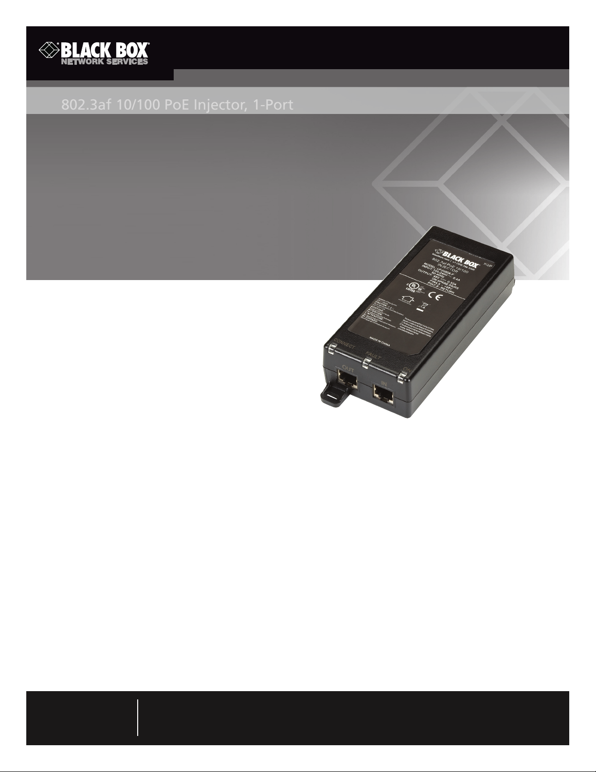
Conforms to the 802.3af standard.
802.3af 10/100 PoE Injector, 1-Port
Use with IP telephones, wireless access points, IP print servers, IP cameras, and Bluetooth®
access points.
1. Specifications
®
Compliance: cUL/UL
Load (Maximum): 0.35 A
Regulation: Line and load: 46 to 49 VDC
under all conditions
Connectors: Data in: (1) RJ-45 (10/100);
Data/PoE out: (1) RJ-45 (10/100);
Power: (1) IEC 320 (3-pin)
Indicators: (3) LEDs: (1) ON, (1) CONNECT, (1) FAULT
Power: AC input voltage range: 90–264 VAC;
AC input voltage rating: 100–240 VAC, 47–63 Hz;
Output: 15.4 W at 48 VDC
Size: 1.4"H x 2.6"W x 5.5"D (1 x 6.6 x 14 cm)
Weight: 0.4 lb. (0.2 kg)
, RoHS
LPJ000A-F
2. Overview
The LPJ000A-F is an entry-level power injector that conforms to the IEEE 802.3af power standard. As defined in 2003, this standard
provides up to 15.4 W of DC power (minimum 44 VDC and 350 mA) to each device. Only 12.95 W of power is ensured to be
available at the powered device because some power is dissipated in the cable.
Use the LPJ000A-F with IP telephones, wireless access points, IP print servers, IP cameras, and Bluetooth access points.
3. Setting Up Your Power Injector
NOTE: Use CAT5e or higher Ethernet cables (not included).
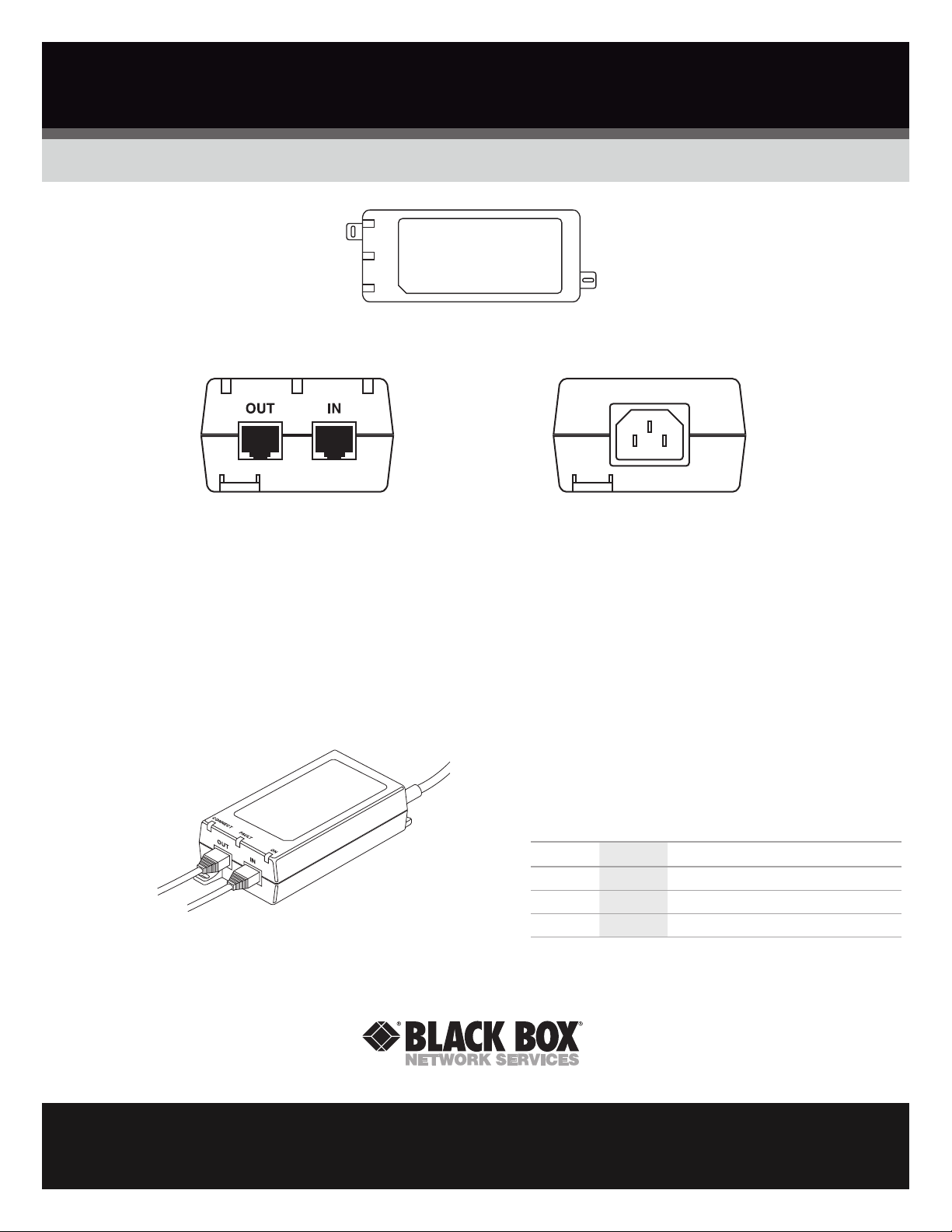
1. Using screws, affix the metal feet on the front and/or rear to a flat surface such as a table or wall. See Figure 1.
NOTE: The power injector should not use the weight of the Ethernet cables for support.
Customer
Support
Information
Order toll-free in the U.S.: Call 877-877-BBOX (outside U.S. call 724-746-5500) •
FREE technical support 24 hours a day, 7 days a week: Call 724-746-5500 or fax 724-746-0746 •
Mailing address: Black Box Corporation, 1000 Park Drive, Lawrence, PA 15055-1018 •
Web site: www.blackbox.com • E-mail: [email protected]
Page 2
Black Box and the Double Diamond logo are registered trademarks of BB Technologies, Inc.
Bluetooth is a registered trademark of The Bluetooth SIG, Inc.
Any other trademarks mentioned in this manual are acknowleged to be the property of the trademark owners.
Insert a screw to
secure the unit to
a surface
Insert a screw to
secure the unit to
a surface
Figure 1. Location of metal feet on the power injector.
Power and Data in
data out
IEC-320 power connector.
Back panel.
Front panel.
Figure 2. Ports on the power injector.
2. Connect the 3-pin IEC320 AC input connector to a power source. Power on the injector.
3. Using CAT5e or higher cable, connect the RJ-45 port on the injector labeled “IN” to your network switch. See Figures 2 and 3.
4. Connect the RJ-45 port labeled “OUT” on the injector over Ethernet cable to the powered device. See Figures 2 and 3.
AC input
Table 1. LEDs.
Power and data
to powered
device
Data input from
network switch
LED Name LED Color Function
ON Green Power ON detected
Fault Red Fault detected
Conne ct Green Valid IEEE 802.3af load detected and connected
Figure 3. Cable connections to the power injector.
5. The LEDs will light to diagnose the connection. See Table 1.
LPJ00 0A-F, versi on 2
©
Copyright 2011. All rights reserved.
FREE, live, 24/7 Tech Support is just 20 seconds away.
724-746-5500 | blackbox.com
 Loading...