

Page 1
FCC and IC RFI Statements; Trademarks
Chapter 3: Operation
NOM Statement
LPH008A
FEDERAL COMMUNICATIONS COMMISSION AND
INDUSTRY CANADA RADIO FREQUENCY INTERFERENCE STATEMENTS
This equipment generate s, uses, and can radiate radio -frequency energy, and if not ins talled and use d
properly, that is, in strict accordance with the manufacturer’s instructions, may cause inter ference to radio
communication. It has be en tested and found to comply with the limits for a Class A computing device in
accordance with the specifications in Subpart B of Par t 15 of FCC rules, which are designed to provide reasonable
protection against such interference when the equipment is operated in a commercial environment. Operation of
this equipment in a residential area is likely to cause interference, in which case the user at his own expense will
be require d to take whatever measures may be ne cessary to co rrect the inte rference.
Changes or modifications not expressly approved by the party responsible for compliance could void the
user’s authority to operate the equipment.
This digital apparatus does not exceed the Class A limits for radio noise emis sion from digital app aratus set
out in the Radio Interference Regulation of Industry Canada.
Le présent appareil numérique n’émet pas de bruits radioélectrique s dépassant l es limites applicables aux
appareil s numériques de la classe A prescrites dans le Rè glement sur le brouillage radio électriq ue publié par
Industrie Canada.
Warranty and Return Information
If you determine that your LPH008A is malfunctioning, do not attempt to alter or
repair the unit. It contains no user-serviceable parts. Contact Black Box Technical
Support at 724-746 -5500 or [email protected].
Before you do, make a record of the history of the problem. We will be able to
provide more efficient and accurate assistance if you have a complete description,
including the nature and duration of the problem, when the problem occurs, and
any particular application that, when used, appears to create the problem or make
it worse.
© Copyright 2014. Black Box Corporation . All rights rese rved. Black Bo x® and the Doub le Diamond
logo are re gistered trade marks of BB Technol ogies, Inc. U L is a registered tra demark of
Under writers Lab oratories. Any t hird-part y trademark s appearing in thi s manual are acknow ledged
to be the prop erty of thei r respectiv e owners.
LPH008A, version 1
FREE! Live, 24/7 Tech Support is just 60 seconds away.
724-746-5500 | blackbox.com
3. Operation
3.1 LED Indicators
LED indicators are located on the front panel of the switch. See Table 1-1.
3.2 Configuration and Setting Methods
No configuration and setting methods are needed.
3.3 Network Connector Pin Assignments
Table 3-2. RJ-45 connector pinout.
MDI
Pin
(1000BASE-T)
1 TP1+ TX+
2 TP1- TX-
3 TP2+ RX+
4 TP3+ —
5 TP3- —
6 TP2- RX-
7 TP4+ —
8 TP4- —
LPH008A
MDI
(10/100BA SE-T)
724-746-5500 | blackbox.com
RJ- 45
connector
Figure 3-1. RJ-45 connector.
RJ-45 8-pin straight-through wiring RJ-45 8-pin crossover wiring
Switch PC (NIC) Switch Switch
3 ---------------------------- 3 3 ----------------------------1
6 ---------------------------- 6 6 ----------------------------2
1 ---------------------------- 1 1 ----------------------------3
2 ---------------------------- 2 2 ----------------------------6
4 ---------------------------- 4 4 ----------------------------7
5 ---------------------------- 5 5 ----------------------------8
7 ---------------------------- 7 7 ----------------------------4
8 ---------------------------- 8 8 ----------------------------5
Figure 3-2. RJ-45 straight-through and
crossover wiring diagrams.
Table 3-2. PoE pin definition.
Pin 10/100BASE-T(X) PSE RJ -45 port Pin 1000BASE-T PSE RJ-45 port
1 TD+ with PoE power input + 1 BI_ DA+ with PoE power input +
2 TD- with PoE power input + 2 BI_ DA- with PoE power input +
3 RD+ with PoE power input - 3 BI_DB + with PoE power input -
6 RD- with PoE power input - 4 BI_DC+
4 Not used 5 BI_DC-
5 Not used 6 BI_ DB- with PoE power input
7 Not used 7 BI_DD+
8 Not used 8 BI_DD-
LPH008A
724-746-5500 | blackbox.com
8-Port Hardened Gigabit PoE+ Switch Quick Start Guide
Link eight 10-/100- /1000-Mbps PoE+ devices to
this tough, industrial-grade switch’s RJ-45
ports.
Delivers PoE+ power to remote powered devices, including IP
cameras, Wi-Fi access points, and VoIP phones.
Customer
Support
Information
Order toll-free in the U.S.: Call 877-877-BBOX (outside U.S.
call 724-746-5500) FREE technical support 24 hours a day, 7 days a
week: Call 724-746-5500 or fax 724-746-0746 Mailing address:
Black Box Corporation, 1000 Park Drive, Lawrence, PA 15055-1018
Web site: www.blackbox.com • E-mail: [email protected]
Chapter 1: Overview
1. Overview
1.1 Introduction
The Hardened Gigabit PoE+ Switch has eight 10/100/1000BASE-TX RJ-45
Ethernet ports and two Power LEDs. It supports Power over Ethernet, which
transmits electrical power, along with data, to remote devices over standard
twisted-pair cable in an Ethernet network. The switch uses a 5-pin terminal
block power connector.
NOTE: The switch should be mounted on a well-grounded place, such as a
metal panel.
1.2 What’s Included
Your package should include the following items. If anything is missing or damaged, contact Black Box Technical Support at 724-746-5500 or info@blackbox.
com.
• (1) Hardened Gigabit PoE+ Switch
• (1) 5-pin terminal block for power input
• This user’s manual
Optional accessories:
• Wallmount kit (45.4" [2.3 cm] thick)
Chapter 1: Overview; Chapter 2: Hardware Installation
1.3 Hardware Description
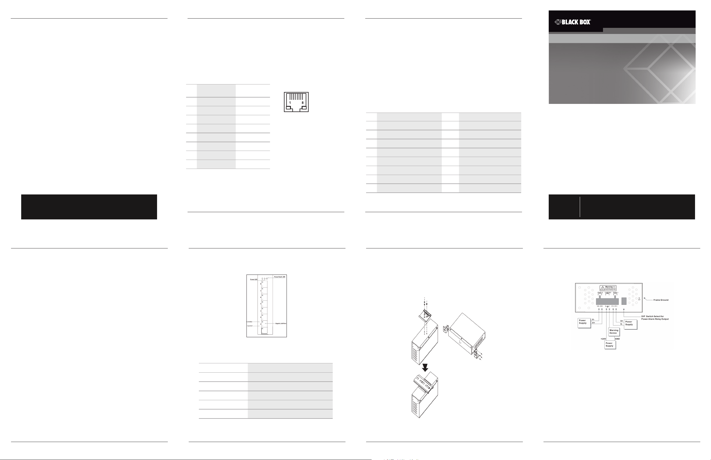
Figure 1-1 shows the Hardened Gigabit PoE+ Switch’s front panel. Table 1-1
describes its components.
Figure 1-1. Front panel.
Table 1-1. LPH008A components.
Component Description
(2) Power LEDs Link to 10- /100- /1000-Mbps Ethernet devices
(1) Power Fault LED Lights when power to the switch is on
(8) Link/Ac t. LEDs Lights when the port is operating
(8) Power Injected LEDs Lights when the port is using PoE+
(8) Gigabit LAN ports Link to PoE+ devices
Chapter 2: Hardware Installation
2. Hardware Installation
Step 1: Installing the Switch on a DIN Rail or Wall
Refer to the illustrations below to mount the switch on a DIN rail or wall.
DIN rail
installation
Wallmount
installation
Chapter 3: Operation
Step 2: Connecting the Power
Refer to the illustration below to connect the power to the switch.
24–36 V DC
Step 3: Connecting the Network Devices
• Connect your devices using standard UTP/STP cable with RJ-45 connectors to the
switch. (For the cable wiring diagrams, refer to the pin assignment in Figure 3-2.)
• The corresponding RJ-45 LED will light if the Ethernet connection is linked
successfully.
• The LED will blink while the switch transfers data.
®
UL
Notice for Power Supply
Use a power supply marked with “LPS,” “Limited Power Source,” or “Class 2” with
output rate 24–36 VDC (5 A maximum at 24 VDC).
24–36 V DC
LPH008A
724-746-5500 | blackbox.com
Page 1
LPH008A
724-746-5500 | blackbox.com
Page 2
LPH008A
Figure 2-1. DIN rail or wallmount installation.
724-746-5500 | blackbox.com
Page 3
LPH008A
724-746-5500 | blackbox.com
Page 4
 Loading...