

Page 1
LMC009A-R5
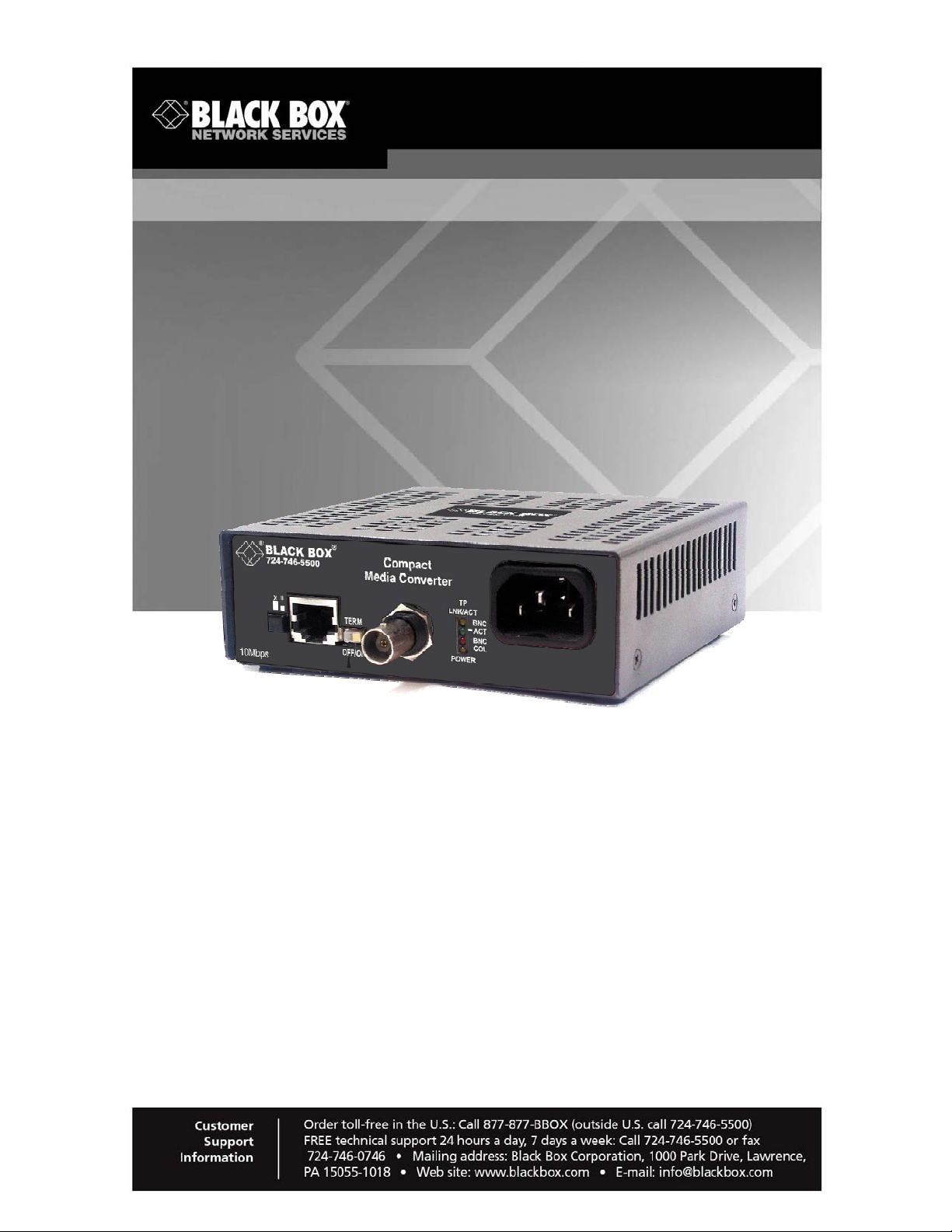
Compact Media Converter TP/BNC 50-ohm
Converts twisted-pair to 50-ohm coax
cable.
This converter uses already-installed 50-ohm analog cable,
so you won’t have to re-cable.
Page 2

FCC and IC RFI Statements
FCC and Industry Canada RF Interference Statements
Class A Digital Device. This equipment has been tested and found to
comply with the limits for a Class A computing device pursuant to Part 15 of
the FCC Rules. These limits are designed to provide reason able protection
against harmful interference in a residential installation. However, there is no
guarantee that interference will not occur in a particular installation. This
equipment generates, uses, and can radiate radio frequency energy, and, if
not installed and used in accordance with the instructions, may cause
harmful interference to radio communications. If this equipment does cause
harmful interference to radio or telephone reception, which can be
determined by turning the equipment off and on, the user is encouraged to
try to correct the interference by one of the following measures:
Reorient or relocate the receiving antenna.
•
• Increase the separation between the equipment and receiver.
• Connect the equipment into an outlet on a circuit different from that to which
the receiver is connected.
• Consult an experienced radio/TV technician for help.
CAUTION
Changes or modifications not expressly approved by the party
responsible for compliance could void the user’s authority to operate
the equipment.
To meet FCC requirements, shielded cables and power cords are required to
connect this device to a personal computer or other Class A certified device.
This digital apparatus does not exceed the Class A limits for radio noise
emission from digital apparatus set out in the Radio Interference Regulation
of Industry Canada.
Page 2 724-746-5500 | blackbox.com LMC009A-R5
Page 3

FCC and IC RFI Statements
Certifications
UL/CUL: Listed to Safety of Information Technology Equipment, including
Electrical Business Equipment.
Class 1 Laser product, Luokan 1 Laserlaite,
Laser Klasse 1, Appareil A’Laser de Classe
European Directive 2002/96/EC (WEEE) requires that any equipment that
bears this symbol on product or packaging must not be disposed of with
unsorted municipal waste. This symbol indicates that the equipment should
be disposed of separately from regular household waste. It is the
consumer’s responsibility to dispose of this and all equipment so marked
through designated collection facilities appointed by government or local
authorities. Following these steps through proper disposal and recycling will
help prevent potential negative consequences to the environment and
human health. For more detailed information about proper disposal, please
contact local authorities, waste disposal services, or the point of purchase for
this equipment.
LMC009A-R5 724-746-5500 | blackbox.com Page 3
Page 4

Table of Contents
Table of Contents
1.
Specifications............................................................................................5
2. Overview: About the Compact Media Converter TP/BNC 5 0-ohm........... 6
3. Install the Compact Media Converter TP/BNC 50-ohm............................ 7
4. Operation..................................................................................................8
4.1 Compact Media Converter TP/BNC 50-ohm Front Panel ........................ 8
4.2 Twisted Pair Crossover/Pass-Through Switch ......................................... 8
4.3 BNC Port Termination...............................................................................8
5. Contacting Black Box................................................................................9
6. Fiber Optic Cleaning Guidelines............................................................. 10
7. Electrostatic Discharge Precautions.......................................................11
Page 4 724-746-5500 | blackbox.com LMC009A-R5
Page 5

Chapter 1: Specifications
1. Specifications
Environmental
Operating Temperature: +32°F to +122°F (0°C to +50°C)
Storage Temperature: -4°F to +158°F (-20°C to +70°C)
Humidity: 5 to 90% (non-condensing)
Input Specifications: 100-240 ±10% V AC, 50/60Hz, 1/0.5A
LMC009A-R5 724-746-5500 | blackbox.com Page 5
Page 6

Chapter 2: Overview: Compact Media Converter TP/BNC 50 Ohm
2. Overview: About the Compact Media Converter TP/BNC 50-ohm
With the Compact Media Converter TP/BNC, 50-ohm coax cable installations
become more accessible.
The Compact Media Converter TP/BNC is a 10 Mbps Ethernet Twisted Pair
to 50-ohm Coax cable (e.g. RG-59) Media Converter, that allows the
continued use of the already-installed 50-ohm analog cable, eliminating the
need to re-cable. As a low-cost, IEEE 802.3 single-conversion, 1U high,
standalone media converter, the Compact Media Converter TP/BNC
converter 10Base-T twisted pair to 10Base-2 thin coax and includes one RJ45 connector and one RG-49 BNC connector. Each Compact Media
Converter TP/BNC includes diagnostic LEDs and an internal 100/240 V AC
power supply.
Part Number
Part Numbe r Description
LMC009A-R5 Compact Media Converter TP/BNC 50-ohm
Page 6 724-746-5500 | blackbox.com LMC009A-R5
Page 7

Chapter 3 Installation
3. Install the Compact Media Converter TP/BNC 50-ohm
The Compact Media Converter TP/BNC converters come ready to install.
Deploy Compact Media Converter TP/BNC units in pairs, or connect a
Compact Media Converter TP/BNC converter to another Black Box
converter. To install a Compact Media Converter TP/BNC converter, first
make sure that the unit is placed on a flat surface. Attach the cables
between the Compact Media Converter TP/BNC and each device that will be
interconnect, the plug the unit into a reliable, filtered power source. Make
sure to connect the BNC port of the Compact Media Converter TP/BNC
converter only to 50-ohm coaxial cable.
When connecting an Ethernet cable to the Compact Media Converter
TP/BNC, make sure the cable corresponds to the Crossover/Pass-Through
switch. When using the Crossover cable, make sure the switch is out, in the
“X” setting. The switch can be pressed again to change the setting.
LMC009A-R5 724-746-5500 | blackbox.com Page 7
Page 8

Chapter 4: Operation
4. Operation
4.1 Compact Media Converter TP/BNC 50-ohm Front Panel
The LEDs
Each Compact Media Converter TP/BNC features diagnostic LEDs. The
following illustration shows the location of the LEDs, and other features, on
the Compact Media Converter TP/BNC. The LED functions for the Compact
Media Converter TP/BNC are as follows:
TP LNK/ACT Glows yellow when a twisted pair link is established and flickers when
data is being received
BNC ACT Flickers green in normal operation indicating activity on the BNC port
BNC COL Flickers red in normal operation indicating activity on the BNC segment
POWER Flickers yellow when the unit is receiving power
4.2 Twisted Pair Crossover/Pass-Through Switch
The twisted pair port on the Compact Media Converter TP/BNC features a
push-button switch, located next to the twisted pair connector, for selecting a
crossover workstation connection or Pass-Through repeater/hub connection.
Select a Pass-Through connection by pressing the push-button IN. A
Crossover connection is selected when the push-button is OUT. If uncertain
whether a Crossover or Pass-Through connection is needed, set the pushbutton to the position that makes the TP LNK (link) LED glow.
4.3 BNC Port Termination
The Compact Media Converter TP/BNC features a 2-position, termination
switch (TERM) next to the BNC connector that allows a think coaxial
segment to be terminated at the port without the use of an external ‘T’
connector/terminator. (See the diagram in the Compact Media Converter
TP/BNC 50-ohm Front Panel section.)
If a ‘T’ connector/terminator is used, this switched must be set in the OFF
(disabled) position. Otherwise, double termination will result, which will
corrupt the signal.
Page 8 724-746-5500 | blackbox.com LMC009A-R5
Page 9

Chapter 5: Contacting Black Box
5. Contacting Black Box
Black Box Customer Service
Order toll-free in the U.S.: Call 877-877-BBOX
(outside U.S. call 724-746-5500)
Free technical support, 24 hours a day, 7 days a week.
Call: 724-746-5500 or Fax: 724-746-0746
Mail order: Black Box Corporation
1000 Park Drive, Lawrence, PA 15055-1018
Web site: www.blackbox.com
E-mail: info@blackbox.com
LMC009A-R5 724-746-5500 | blackbox.com Page 9
Page 10

Chapter 6: Fiber Optic Cleaning Guidelines
6. Fiber Optic Cleaning Guidelines
Fiber Optic transmitters and receivers are extremely sus ceptible to
contamination by particles of dirt or dust, which can obstruct the optic path
and cause performance degradation. Good s y stem performance requires
clean optics and connector ferrules.
1. Use fiber patch cords (or connectors, if you terminate your own fiber) only
from a reputable supplier; low-quality components can cause many hard-todiagnose problems in an installation.
2. Dust caps are installed at Black Box t o ensur e factory-clean optical devices.
These protective caps should not be removed u ntil the mom ent of connecting
the fiber cable to the device. Should it be necessary to disconnect the fiber
device, reinstall the protective dust caps.
3. Store spar e c a ps i n a dust- f ree env ironment such as a sealed plastic bag or
box so that when reinstalled they do not introduce any contamination to the
optics.
4. If you suspect that the optics have been contaminated, alternate between
blasting with clean, dry, compressed air and flushing with methanol to remove
particles of dirt.
Page 10 724-746-5500 | blackbox.com LMC009A-R5
Page 11

Chapter 7: Electrostatic Discharge Precautions
7. Electrostatic Discharge Precautions
Electrostatic discharge (ESD) can cause damage to any product, add-in
modules or stand alone units, containing electronic components. Always
observe the following precautions when installing or handling these kinds of
products.
1. Do not remove unit from its protective packaging until ready to install.
2. Wear an ESD wrist grounding strap before handling any module or
component. If the wrist strap is not available, maintain grounded contact with
the system unit throughout any procedure requiring ESD protection.
3. Hold the units by the edges; do not touch the electronic components or gold
connectors.
4. After removal, always place the boards on a grounded, static-free surface,
ESD pad or in a proper ESD bag. Do not slide the modules or stand alone
units over any surface.
WARNING! Integrated circuits and fiber optic components
are extremely susceptible to electrostatic discharge damage.
Do not handle these components directly unless you are a
qualified service technician and use tools and techniques that
conform to accepted industry practices.
LMC009A-R5 724-746-5500 | blackbox.com Page 11
Page 12

LMC009A-R5, Rev. 1 51-80124BB-00 B0
 Loading...