

Page 1

LMC5022C-R3 LMC5110C-R3 LMC5116C-R3 LMC5182C-R3
LMC5023C-R3 LMC5111C-R3 LMC5117C-R3
LMC5026C-R3 LMC5113C-R3 LMC5180C-R3
LMC5027C-R3 LMC5114C-R3 LMC5181C-R3
High-Density Media Converter System II Layer 2 Modules
True Layer 2 conversion enables
you to extend your network
up to 40 kilometers over duplex fiber.
Page 2

FCC and IC RFI Statements
FCC and Industry Canada RF Interference Statements
Class B Digital Device. This equipment has been tested and found to comply with
the limits for a Class B computing device pursuant to Part 15 of the FCC Rules.
These limits are designed to provide reasonable protection against harmful
interference in a residential installation. However, there is no guarantee that
interference will not occur in a particular installation. This equipment generates,
uses, and can radiate radio frequency energy, and, if not installed and used in
accordance with the instructions, may cause harmful interference to radio
communications. If this equipment does cause harmful interference to radio or
telephone reception, which can be determined by turning the equipment off and on,
the user is encouraged to try to correct the interference by one of the following
measures:
• Reorient or relocate the receiving antenna.
• Increase the separation between the equipment and receiver.
• Connect the equipment into an outlet on a circuit different from that to which the
receiver is connected.
• Consult an experienced radio/TV technician for help.
CAUTION
Changes or modifications not expressly approved by the party responsible for
compliance could void the user’s authority to operate the equipment.
To meet FCC requirements, shielded cables and power cords are required to
connect this device to a personal computer or other Class B certified device.
This digital apparatus does not exceed the Class B limits for radio noise
emission from digital apparatus set out in the Radio Interference Regulation of
Industry Canada.
Page 2 724-746-5500 | blackbox.com LMC5022C-R3
Page 3

Certifications
Certifications
Class 1 Laser product, Luokan 1 Laserlaite,
Laser Klasse 1, Appareil A’Laser de Classe
European Directive 2002/96/EC (WEEE) requires that any equipment that
bears this symbol on product or packaging must not be disposed of with
unsorted municipal waste. This symbol indicates that the equipment should be
disposed of separately from regular household waste. It is the consumer’s
responsibility to dispose of this and all equipment so marked through
designated collection facilities appointed by government or local authorities.
Following these steps through proper disposal and recycling will help prevent
potential negative consequences to the environment and human health. For
more detailed information about proper disposal, please contact local
authorities, waste disposal services, or the point of purchase for this equipment.
LMC5022C-R3 724-746-5500 | blackbox.com Page 3
Page 4

Table of Contents
Table of Contents
Part Numbers ..................................................................................................5
1. Specifications............................................................................................6
2. Overview: About the High-Density Media Converter System II Layer 2
Modules........................................................................................................... 7
3. Configuration............................................................................................. 8
4. Install the High-Density Media Converter System II Layer 2 Modules.....9
4.1 Managed Modules .................................................................................... 9
4.1.1 Configuration Control and SNMP Management.................................9
4.2 Unmanaged Modules..............................................................................10
4.3 FX LinkLoss, TX LinkLoss, Link Fault Pass-Through, Far End Fault and
FiberAlert....................................................................................................... 11
4.3.1 Link Integrity.....................................................................................11
4.3.2 FX LinkLoss (FXLL).......................................................................... 12
4.3.3 TX LinkLoss (TXLL).......................................................................... 12
4.3.4 Link Fault Pass-Through (LFPT)......................................................12
4.3.5 FiberAlert and Far End Fault............................................................ 13
4.4 Auto Negotiation on High-Density Media Converter System II Layer 2
Modules......................................................................................................... 15
4.5 AutoCross Feature for Twisted Pair Connection ....................................15
5. Operation................................................................................................16
5.1 LED Operation........................................................................................16
6. Troubleshooting......................................................................................17
7. Contacting Black Box..............................................................................18
8. Fiber Optic Cleaning Guidelines............................................................. 19
Electrostatic Discharge Precautions.............................................................. 19
Page 4 724-746-5500 | blackbox.com LMC5022C-R3
Page 5

Part Numbers
Part Number Description
LMC5022C-R3 TX/FX-MM1300-ST
LMC5023C-R3 TX/FX-MM1300-SC
LMC5026C-R3 TX/FX-SM1310/PLUS-ST
LMC5027C-R3 TX/FX-SM1310/PLUS-SC
LMC5110C-R3 TX/FX-SM1310/LONG-SC
LMC5111C-R3 TX/FX-SM1310/LONG-ST
LMC5113C-R3 TX/SSFX-SM1310-SC (1310xmt/1550rcv)
LMC5114C-R3 TX/SSFX-SM1550-SC (1550xmt/1310rcv)
LMC5116C-R3 TX/SSFX-SM1310/PLUS-SC (1310xmt/1550rcv)
LMC5117C-R3 TX/SSFX-SM1550/PLUS-SC (1550xmt/1310rcv)
LMC5180C-R3 TX/FX-SM1550/LONG-SC
LMC5181C-R3 TX/FX-MM850-SC
LMC5182C-R3 TX/FX-MM850-ST
Part Numbers
LMC5022C-R3 724-746-5500 | blackbox.com Page 5
Page 6

Chapter 1: Specifications
1. Specifications
DC Input L2 w/LFPT: 0.80 Amp @ 5V
Operating Temperature: +32° F to +122° F (0° C to +50° C)
Storage Temperature: 0° F to +122° F (-20° C to +70° C)
Humidity: 5 - 95% (non-condensing)
Fiber Optic Specifications For fiber optic specifications, please visit:
http://www.blackbox.com
Page 6 724-746-5500 | blackbox.com LMC5022C-R3
Page 7

Chapter 2: Overview
2. Overview: About the High-Density Media Converter System II Layer 2
Modules
The L2 is a Fast Ethernet module which provides a single conversion between
100BASE-TX twisted pair and 100BASE-FX/SX single-mode or multi-mode
fiber. Each L2 includes one RJ-45 connector and one pair of ST or SC fiber
optic connectors
Also available in a single-strand fiber version, L2 TX/SSFX allows two
wavelengths to share one fiber strand — Full-Duplex data travels on different
wavelengths, for example (1310 nm and 1550 nm) — doubling the capacity of
fiber.
The L2 is SNMP-manageable and can be installed into the modular, SNMPmanageable High-Density Media Converter System II Layer 2 chassis, which is
unmanaged.
LMC5022C-R3 724-746-5500 | blackbox.com Page 7
Page 8

Chapter 3: Configuration
3. Configuration
The L2 has user-configurable features (e.g., FiberAlert (FA), TX LinkLoss
(TXLL), FX LinkLoss (FXLL), Link Fault Pass-Through (LFPT) and Far End
Fault (FEF)). Refer to the Managed Media Converter Module DIP Switch
Configuration Table for information on available features. Instructions for
installing and configuring both managed (via an SNMP-compatible
management application like iView²) and unmanaged modules follow.
Page 8 724-746-5500 | blackbox.com LMC5022C-R3
Page 9

Chapter 4: Install the High-Density Media Converter System II Layer 2
Modules
4. Install the High-Density Media Converter System II Layer 2 Modules
The Managed Media Converter Modules install in Black Box SNMP
manageable High-Density Media Converter System II chassis.
NOTE
All modules are hot-swappable.
To install a Managed Media Converter Module:
1. Remove the blank bracket covering the slot where the module is to be
installed by removing the screws on the outside edges of the bracket.
2. Slide the Managed Media Converter Modules into the chassis, via the
cardguides, until the module is seated securely in the connector.
3. Secure the module to the chassis by tightening the captive screw.
4. Save any “blanks” removed during installation for future use if the
configuration requirements change
4.1 Managed Modules
To manage one or more L2(s), an SNMP agent must be present in the chassis.
To configure Managed Modules, install the module first, and then configure
using the management software.
All Fiber Type information is now loaded into the NVRAM during manufacturing.
This is viewed only via iView² software, within the modules details.
Requirements:
• SNMP Firmware version C2
• iView² 1.8.6 or higher
4.1.1 Configuration Control and SNMP Management
Some High Density L2 Modules offer Configuration Control; labels on the front
faceplate are identified as such. Configuration Control has been implemented
to assist the end user by retaining the latest configuration regardless of how
that configuration was implemented (via DIP Switch settings or SNMP), when
an SNMP Management Module is present in a managed chassis.
Historically, if an SNMP Management Module was installed in a chassis, SNMP
would override the DIP Switch settings of a module. Using Configuration
Control, the end user has three conditions under which the configuration of an
SNMP Manageable Module may be impacted:
• Changing or installing an SNMP Management Module into a chassis with a
High Density L2 Modules with Configuration Control populated in a chassis
- The High Density L2 Module with Configuration Control will transfer its
saved configurations to the SNMP Management Module. If there is no
LMC5022C-R3 724-746-5500 | blackbox.com Page 9
Page 10

Chapter 4: Install the High-Density Media Converter System II Layer 2
Modules
SNMP Management Module, the High Density L2 Module with
Configuration Control will function based on its DIP Switch settings. If
the DIP Switches have not been changed, the stored configuration will
be used. The stored configuration can be extracted from the SNMP
Management Module or the DIP Switches.
• Replacing the same type of a High Density L2 Module with Configuration
Control
- If the DIP Switch settings are the same as the settings on the removed
High Density L2 Module, the new High Density L2 Modules with
Configuration Control gets its configuration settings from the SNMP
Management Module.
- If the DIP Switch settings are different, then the configuration of the
module is determined by the DIP Switch settings. (The settings are
forwarded to the SNMP Management Module and the values are
saved.)
• Installing a different model of a High Density L2 Module with Configuration
Control
- If another type of module is installed into the same slot in a chassis, the
SNMP Management Module clears the memory of the previous
configuration for that slot; the installed SNMP Manageable Module
configures itself, and its configuration is forwarded to the SNMP
Management Module, where the values are saved.
The SNMP Write Lock switch does not impact any High Density L2 Module or
High Density L2 Module with Configuration Control. Removing and installing a
new SNMP Management Module will no longer impact these modules either.
However, if there is a mixture of High Density L2 Modules with and without
Configuration Control, the Write Lock Switch and a new SNMP Management
Module must be taken into consideration.
If the command cleandb is applied to an SNMP Management Module, all the
settings for the modules will be removed, but the Configuration Control modules
will still be based on the last change made, while those without Configuration
Control will be set to their default settings.
4.2 Unmanaged Modules
Before installing, configure the L2 modules for desired features. The table on
the next page indicates the available features and settings for the L2 modules.
After configuring the DIP Switches for the desired settings, install the module
and connect the appropriate cables (refer to the Installating a High-Density
Media Converter System II Layer 2 section for more information).
Page 10 724-746-5500 | blackbox.com LMC5022C-R3
Page 11

Chapter 4: Install the High-Density Media Converter System II Layer 2
Modules
DIP Switch on S1 Feature Default Setting
1
2
3
4
5
6
7
8
Auto Negotiation (AN) ON
Far End Fault (FEF) OFF
FX LinkLoss (FXLL) OFF
TX LinkLoss (TXLL) OFF
FiberAlert (FA) OFF
Factory Default OFF
Factory Default OFF
Factory Default OFF
4.3 FX LinkLoss, TX LinkLoss, Link Fault Pass-Through, Far End Fault
and FiberAlert
L2 modules include the troubleshooting features FiberAlert, TXLL, FXLL, FEF
and LFPT that help locate silent failures on a network. Before attempting to
install the module(s), understand how these features work and react to a
specific network configuration.
4.3.1 Link Integrity
During normal operation, link integrity pulses are transmitted by all point-topoint Ethernet devices. When a Black Box media converter receives valid link
LMC5022C-R3 724-746-5500 | blackbox.com Page 11
Page 12

Chapter 4: Install the High-Density Media Converter System II Layer 2
Modules
pulses, it knows that the device to which it is connected is up and sending
pulses, and that the copper or fiber cable coming from that device is intact. The
appropriate “LNK” (link) LED is lit to indicate this.
The Black Box media converter also sends out link pulses from its copper and
fiber transmitters, but normally has no way of knowing whether the cable to the
other device is intact and the link pulses are reaching the other end. The
combination of FiberAlert and LinkLoss allows this information to be obtained
even when physical access to a remote device (and its link integrity LED) is not
available.
4.3.2 FX LinkLoss (FXLL)
FX LinkLoss is a troubleshooting feature. When enabled, if a fault occurs on
the fiber segment of a conversation, FX LinkLoss detects the fault and passes
this information to the twisted pair segment. If a media converter is not
receiving a fiber link, FX LinkLoss disables the transmitter on the media
converter’s twisted pair port. This results in a loss of link on the device
connected to the twisted pair port.
4.3.3 TX LinkLoss (TXLL)
TX LinkLoss is a troubleshooting feature. When enabled, if a fault occurs on
the twisted pair segment of a conversion, TX LinkLoss detects the fault and
passes this information to the fiber segment. If a media converter is not
receiving a twisted pair link, TX LinkLoss disables the transmitter on the media
converter's fiber port. The result is in a loss of the link on the device connected
to the fiber port.
4.3.4 Link Fault Pass-Through (LFPT)
Link Fault Pass-Through (LFPT) is a troubleshooting feature that combines TX
and FX LinkLoss from both the local and remote L2 modules. LFPT is enabled
by turning on both FX and TX LinkLoss on both modules. This feature allows
either end of the conversion to detect a link fault occurring at the other end of
the media conversion chain.
Page 12 724-746-5500 | blackbox.com LMC5022C-R3
Page 13

Chapter 4: Install the High-Density Media Converter System II Layer 2
Modules
Regardless if there is a break in segment 1, 2 or 3, the link will drop on the
switches at both ends. The link fault is passed through the media conversion
and is observed at each end. It acts just like it would if the devices were
directly connected.
For more information on LinkLoss/FiberAlert, visit the Black Box Web site at
http://www.blackbox.com. If unsure of how to implement these features in a
specific configuration, contact Black Box Technical Support at 877-877-2269.
4.3.5 FiberAlert and Far End Fault
Modules ship from the factory with troubleshooting features disabled.
FiberAlert (FA)
FiberAlert minimizes the
problems associated with
the loss of one strand of
fiber. If a strand is
unavailable, the Black
Box device at the receiver
end notes the loss of link.
The device will then stop transmitting data and the link signal until a signal or
link pulse is received. The result is that the link LED on BOTH sides of the fiber
connection will go out indicating a fault somewhere in the fiber loop. Using
FiberAlert, a local site administrator is notified of a fault and can quickly
determine where a cable fault is located.
LMC5022C-R3 724-746-5500 | blackbox.com Page 13
Page 14

Chapter 4: Install the High-Density Media Converter System II Layer 2
Modules
WARNING
Enable FiberAlert at the remote side of a media conversion only. Enabling it on both
sides would keep both transmitters disabled indefinitely.
By default FA is disabled. When enabled if, a fault occurs on the fiber line,
affecting data in one direction, FA stops sending signal in the opposite
direction. FXLL will act on this lack of signal, propagating the loss of like to the
copper port when FXLL is enabled.
Far End Fault
By default, FEF is disabled. When enabled, and a fault occurs on the fiber line,
affecting data in one direction, an FEF signal will be sent in the opposite
direction, indicating the fault. FXLL will act on this signal propagating the loss of
link to the copper port when FXLL is enabled.
FEF versus FA
FEF is preferred when the devices at both ends of the fiber can interpret the
FEF signal. This allows FEF to be turned on at both ends, which will engage
the FEF regardless of which direction the fault occurs. (Please refer to diagram
on previous page) For example if a fault should occur on segment 2 in the
direction of segment 1 to 3, FEF would be engaged on the L2 between
segment 2 and 3. This would then send a signal back to the L2 between
segment 1 and 2. If the L2 between segment 1 and 2 is in a managed chassis,
the chassis would send a trap that the port is down. Alternatively, if the L2 is
not in a managed chassis, FXLL could be engaged to propagate the fault onto
the copper port; this would cause segment 1 to show no link on both end s.
FA is used when connecting to a device that does not support FEF. If an FEF
signal is sent to a device that does not support FEF, the device acts as if there
is still a good connection. The FEF signal is mistaken for data. FA works
similar to FEF, in that when there is a fault in one direction of the fiber, it acts
on the fiber in the opposite direction. But unlike FEF, FA sends no signal.
Because of this, FA can not be enabled on both ends. If it is enabled and a
fault occurs, FA will turn signal off in the opposite direction; the device on the
other side of the fiber will see the loss of signal and engage FA, turning off
signal. The net result will be the signal turned off in both directions, even after
the fault has been repaired.
It is highly recommended that only one is chosen, either FEF or FA. If both are
selected FA will take precedence over FEF.
Page 14 724-746-5500 | blackbox.com LMC5022C-R3
Page 15
Chapter 4: Install the High-Density Media Converter System II Layer 2
Modules
4.4 Auto Negotiation on High-Density Media Converter System II Layer 2
Modules
L2 modules include the feature Auto Negotiation. When Auto Negotiation is
enabled, the module negotiates as a 100 Mbps full-duplex device. If the
connected device can operate at 100 Mbps full-duplex, a link is established.
Auto Negotiation (DIP Switch #1) is enabled by default.
If the twisted pair port on the other device does not have the ability to Auto
Negotiate or if the 100 Mbps half-duplex connection is desired, then Auto
Negotiation must be disabled. Half- and full-duplex settings must be set
manually and match on both devices.
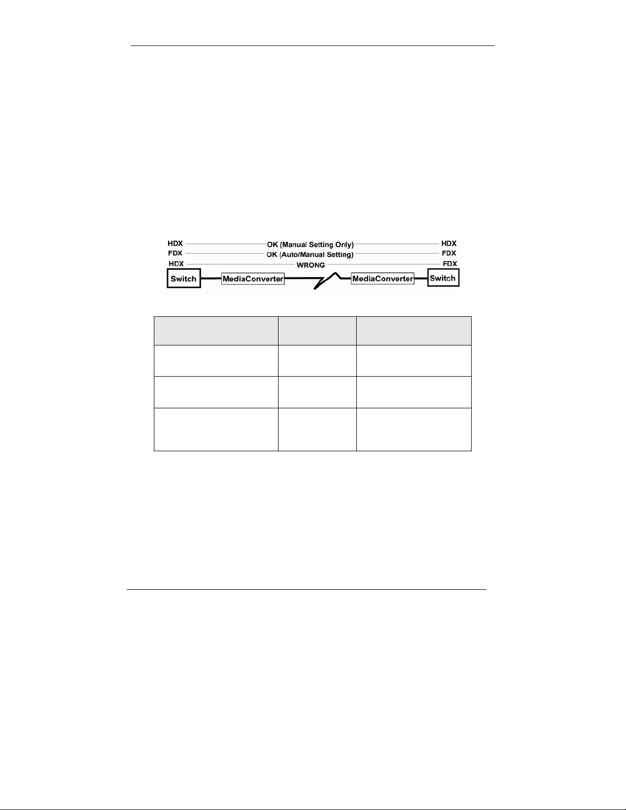
The following diagram shows a typical application and with three possible
configurations.
End-to-End
Switch TX/FX
Connection
Half-Duplex Configure
HDX manually
Full-Duplex Configure
FDX manually
Full-Duplex Auto
Negotiation is
Auto Negotiation is
OFF
Auto Negotiation is
OFF
Auto Negotiation is
ON
ON
Configure Auto Negotiation on a L2 by adjusting the DIP Switch setting (for
unmanaged modules) or via the management software. Refer to the DIP
Switch table for switch location and settings.
4.5 AutoCross Feature for Twisted Pair Connection
All twisted pair ports on the L2 includes AutoCross, a feature that automatically
selects between a crossover workstation and a straight-thro ugh connection
depending on the connected device.
LMC5022C-R3 724-746-5500 | blackbox.com Page 15
Page 16

Chapter 5: Operation
5. Operation
5.1 LED Operation
Each L2 module features diagnostic LEDs that provide information on features
and ports.
Upgrade LED Stacks
Upper Function State
FEF
TXLL
LNK
DIS
Upper Function State
FA
FXLL
LNK
DIS
Fiber Far End Fault ON Green
TX LinkLoss/Blink if Active ON Green
FiberLink is valid/Flash on Activity ON Green
Software Disabled TX Port On Yellow
FiberAlert enabled/Blink Active ON Green
FX LinkLoss/Blink if Active ON Green
FX LinkLoss is valid/Flash on Activity ON Green
Software Disabled fiber port
On Yellow
(via iView²)
Page 16 724-746-5500 | blackbox.com LMC5022C-R3
Page 17

Chapter 6: Troubleshooting
6. Troubleshooting
• During install ation, first test the fiber and twisted pair connections with all
troubleshooting features disabled, then enable these features, if desired,
just before final installation. This will reduce the features’ interference with
testing.
• When worki ng with units where the features cannot be disabled, establish
both the twisted pair and fiber connections before the link LEDs will light.
• To test a L2 by itself, first, have an appropriate fiber patch cable, then
follow these steps:
1. Connect the L2 to the twisted pair device with a twisted pair cable.
2. Loop a single strand of fiber from the transmit port to the receive port of
the L2.
3. Verify that both the twisted pair and the fiber link are lit (see LEDs,
below) on the L2.
• Use the appropriate twisted pair cable, and have the crossover/pass-
through switch set correctly.
• Whenever possible, set the devices connected to the L2 (hub, switch, NIC
card) to the desired speed and Duplex setting, and turn Auto Negotiation
OFF. Refer to Auto Negotiation on L2, also configure the devices on the
opposite sides of the L2 to operate at the same speed and Duplex setting.
NOTE
Some 10/100 devices can not be set by the end user, and must Auto Negotiate to
receive a signal.
LMC5022C-R3 724-746-5500 | blackbox.com Page 17
Page 18

Chapter 7: Contacting Black Box
7. Contacting Black Box
Black Box Customer Service
Order toll-free in the U.S.: Call 877-877-BBOX
(outside U.S. call 724-746-5500)
Free technical support, 24 hours a day, 7 days a week.
Call: 724-746-5500 or Fax: 724-746-0746
Mail order: Black Box Corporation
1000 Park Drive, Lawrence, PA 15055-1018
Web site: www.blackbox.com
E-mail: info@blackbox.com
WARNING
Disconnect all power supplies before servicing.
Page 18 724-746-5500 | blackbox.com LMC5022C-R3
Page 19

Chapter 8: Fiber Optic Cleaning & ESD Precautions
8. Fiber Optic Cleaning Guidelines
Fiber Optic transmitters and receivers are extremely susceptible to
contamination by particles of dirt or dust, which can obstruct the optic path and
cause performance degradation. Good system performance requires clean
optics and connector ferrules.
1. Use fiber patch cords (or connectors, if you terminate your own fiber) only from a
reputable supplier; low-quality components can cause many hard-to-diagnose
problems in an installation.
2. Dust caps are installed at Black Box to ensure factory-clean optical devices.
These protective caps should not be removed until the moment of connecting the
fiber cable to the device. If you need to disconnect the fiber device, reinstall the
protective dust caps.
3. Store spare caps in a dust-free environment such as a sealed plastic bag or box
so that when reinstalled they do not introduce any contamination to the optics.
4. If you suspect that the optics have been contaminated, alternate between
blasting with clean, dry, compressed air and flushing with methanol to remove
particles of dirt.
Electrostatic Discharge Precautions
Electrostatic discharge (ESD) can cause damage to any product, add-in
modules or stand alone units, containing electronic components. Always
observe the following precautions when installing or handling these kinds of
products.
1. Do not remove unit from its protective packaging until ready to install.
2. Wear an ESD wrist grounding strap before handling any module or component.
If the wrist strap is not available, maintain grounded contact with the system unit
throughout any procedure requiring ESD protection.
3. Hold the units by the edges; do not touch the electronic components or gold
connectors.
4. After removal, always place the boards on a grounded, static-free surface, ESD
pad or in a proper ESD bag. Do not slide the modules or stand alone units over
any surface.
WARNING! Integrated circuits and fiber optic components
are extremely susceptible to electrostatic discharge damage.
Do not handle these components directly unless you are a
qualified service technician and use tools and techniques that
conform to accepted industry practices.
LMC5022C-R3 724-746-5500 | blackbox.com Page 19
Page 20

LMC5022C-R3, Rev. 1 50-80921BB-01 Rev A0
 Loading...