

Page 1

LMC400 Series
LMC4000 Series
Micro Mini Converter
Product Overview
The Micro Mini Gigabit fiber to 10/100/1000BASE-T and Fast Ethernet fiber to
10/100/1000BASE-T media converters are ideal for mobile applications where light
weight, compact size and low power are critical requirements.
These units deliver plug-and-play set up with an RJ-45 port that auto-negotiates the
speed, duplex mode and cross-over functions for laptops with 10BASE-T, 100BASE-TX
or 1000BASE-T Ethernet.
Installation Procedure
1) Connect Cables
a. The Micro Mini Converters can be wall mounted using the optional wall mount
bracket (LMC400-WALL) or placed on a at level surface.
To power the module using the USB cable, connect the USB Standard Type A
connector to a USB port on the computer. Then connect the USB Micro-B connector
at the other end of the cable to the connector on the back of the media converter.
Conrm that the module has powered up properly by checking the power status
LED located on the top of the module.
To power the module using the AC/DC adapter, connect the USB Standard Type A
connector to the AC/DC adapter and connect the AC/DC adapter to the AC outlet.
Next, connect the USB Micro-B connector at the end of the cable to the connector on
the back of the media converter. Conrm that the module has powered up properly
by checking the power status LED located on the top of the module.
b. Connect the UTP port via a Category 5 or better cable to a 10BASE-T, 100BASE-TX
or 1000BASE-T Ethernet device.
c. When using xed ber port models, connect the appropriate multimode or single-
mode ber cable to the ber port of the installed module. It is important to ensure
that the transmit (Tx) is attached to the receive side of the device at the other end and
the receive (Rx) is attached to the transmit side. Single-ber (SF) media converter
models operate in pairs. The Tx wavelength must match the Rx wavelength at the
other end and the Rx wavelength must match the Tx wavelength at the other end.
When using an SFP model, insert the SFP Fiber transceiver into the Port 1 SFP
receptacle on the module.
NOTE: The release latch of the SFP Fiber transceiver must be in the closed (up)
position before insertion.
2) Verify Operation
Once the module has been installed, verify the module is operational by viewing the
LED indicators.
724-746-5500 | blackbox.com
Page 1
Page 2
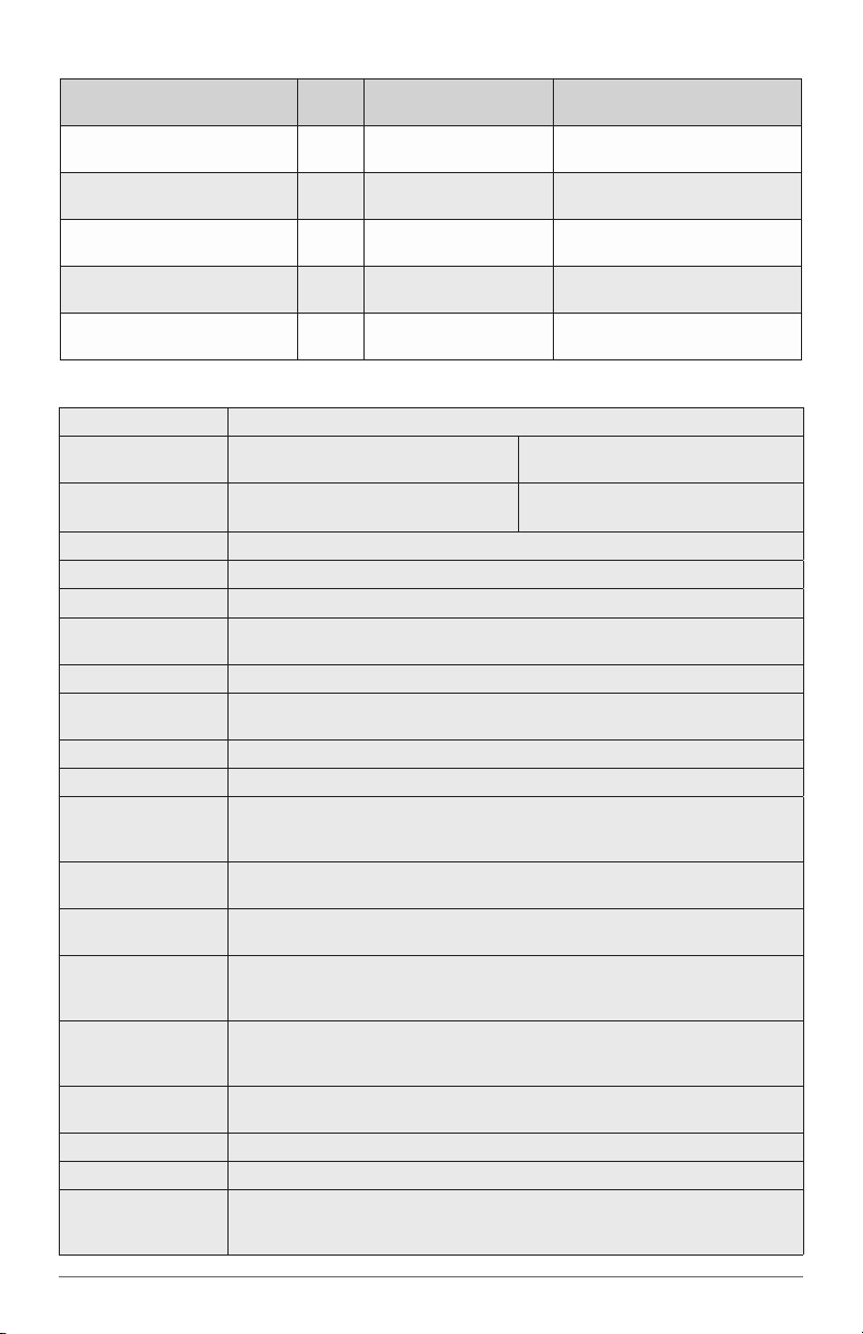
LED Function
“Legend”
Power
“PWR”
Fiber Link Activity
“F/O”
UTP Link Activity
“10”
UTP Link Activity
“1000”
UTP Link Activity
“10” and “1000”
Color OFF State ON/Blinking State
Green No power ON: Module has power
Green No ber link
Green No UTP link
Green No UTP link
Green No UTP link
ON: Fiber link
Blinking: Data activity
ON: Port linked at 10M
Blinking: Data activity
ON: Port linked at 1000M
Blinking: Data activity
ON: Port linked at 100M
Blinking: Data activity
Specications
Model Micro Mini Converter
Description
Protocols
Frame Size 10,240 byte max frame size
Compliance UL, CE, FCC 15 Class B
UTP Cable EIA/TIA 568A/B, Cat 5 and higher
Fiber Cable
Copper Connector RJ45
Fiber Connector
LED Display Pwr, F/O, UTP
Dimensions W: 1.75” x L: 2.25” x H: 0.84”
Weight
DC Power Input
Connector
DC Power
Requirements
AC Power
Requirements (US)
AC Power
Requirements (Univ.)
Temperature
Humidity 5 to 95% (non-condensing)
Altitude -100m to 4000m
MTBF (hrs)
1000BASE-X Fiber to
10/100/1000BASE-T UTP Converter
10BASE-T, 100BASE-TX, 1000BASE-T,
1000BASE-X
Multimode:
Single-mode:
SFP:
Dual Fiber:LCSC, ST
without AC/DC adapter:
with USB cable:
with AC/DC adapter (US) and USB:
USB Micro-B
0.5A @ 5VDC
100-120VAC
50-60Hz
0.02A @ 120V
100-240VAC
50-60Hz
0.02A @ 120VAC
Standard:
Storage:
without AC/DC adapter:
US AC/DC adapter:
Univ AC/DC adapter:
100BASE-FX Fiber to
10/100/1000BASE-T UTP Converter
10BASE-T, 100BASE-TX, 1000BASE-T,
50/125, 62.5/125, 100/140um
9/125um
2.5 oz.
3.8 oz.
5.4 oz.
0 to 50°C
-40 to 80°C
1,300,000
50,000
200,000
100BASE-FX
Page 2
724-746-5500 | blackbox.com
Page 3
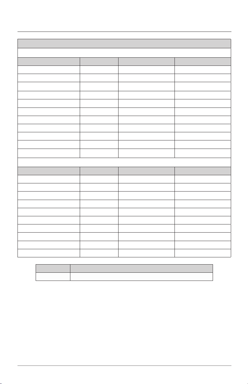
Micro Mini Converter
Ordering Information
US Power Supply
Model Fiber Speed Fiber type Distance
LMC400A 100M SFP --
LMC401A 100M 1310nm, MM, ST 5km / 16,400 ft.
LMC402A 100M 1310nm, MM, SC 5km / 16,400 ft.
LMC403A 100M 1310nm, SM, ST 30km / 18.6 mi.
LMC404A 100M 1310nm, SM, SC 30km / 18.6 mi.
LMC4000A 1000M SFP --
LMC4001A 1000M 850nm, MM, ST 550m / 1800 ft.
LMC4002A 1000M 850nm, MM, SC 550m / 1800 ft.
LMC4003A 1000M 1310nm, SM, ST 12km / 7.4 mi.
LMC4004A 1000M 1310nm, SM, SC 12km / 7.4 mi.
Universal Power Supply
Model Fiber Speed Fiber type Distance
LMC400AE 100M SFP --
LMC401AE 100M 1310nm, MM, ST 5km / 16,400 ft.
LMC402AE 100M 1310nm, MM, SC 5km / 16,400 ft.
LMC403AE 100M 1310nm, SM, ST 30km / 18.6 mi.
LMC404AE 100M 1310nm, SM, SC 30km / 18.6 mi.
LMC4000AE 1000M SFP --
LMC4001AE 1000M 850nm, MM, ST 550m / 1800 ft.
LMC4002AE 1000M 850nm, MM, SC 550m / 1800 ft.
LMC4003AE 1000M 1310nm, SM, ST 12km / 7.4 mi.
LMC4004AE 1000M 1310nm, SM, SC 12km / 7.4 mi.
Model No. Description
LMC400-WALL Micro Mini Converter - wall mount bracket
724-746-5500 | blackbox.com
Page 3
Page 4

NOM Statement
FEDERAL COMMUNICATIONS COMMISSION AND
INDUSTRY CANADA RADIO FREQUENCY INTERFERENCE STATEMENTS
This equipment generates, uses, and can radiate radio-frequency energy,
and if not installed and used properly, that is, in strict accordance with the
manufacturer’s instructions, may cause inter ference to radio communication.
It has been tested and found to comply with the limits for a Class B computing
device in accordance with the specifications in Subpart B of Part 15 of FCC rules,
which are designed to provide reasonable protection against such interference
when the equipment is operated in a commercial environment. Operation of
this equipment in a residential area is likely to cause interference, in which case the
user at his own expense will be required to take whatever measures may be necessary to correct the interference.
Changes or modifications not expressly approved by the party responsible
for compliance could void the user’s authority to operate the equipment.
This digital apparatus does not exceed the Class B limits for radio noise
emis sion from digital apparatus set out in the Radio Interference Regulation
of Industry Canada.
Le présent appareil numérique n’émet pas de bruits radioélectriques dépassant les
limites applicables aux appareils numériques de la classe A prescrites dans le
Règlement sur le brouillage radioélectrique publié par Industrie Canada.
Normas Oficiales Mexicanas (NOM)
Electrical Safety Statement
INSTRUCCIONES DE SEGURIDAD
1. Todas las instrucciones de seguridad y operación deberán ser leídas antes
de que el aparato eléctrico sea operado.
2. Las instrucciones de seguridad y operación deberán ser guardadas para
referencia futura.
3. Todas las advertencias en el aparato eléctrico y en sus instrucciones de
operación deben ser respetadas.
4. Todas las instrucciones de operación y uso deben ser seguidas.
Page 4
724-746-5500 | blackbox.com
Page 5

Micro Mini Converter
5. El aparato eléctrico no deberá ser usado cerca del agua—por ejemplo,
cerca de la tina de baño, lavabo, sótano mojado o cerca de una alberca,
etc..
6. El aparato eléctrico debe ser usado únicamente con carritos o pedestales
que sean recomendados por el fabricante.
7. El aparato eléctrico debe ser montado a la pared o al techo sólo como sea
recomendado por el fabricante.
8. Servicio—El usuario no debe intentar dar servicio al equipo eléctrico más allá
lo descrito en las instrucciones de operación. Todo otro servicio deberá ser
referido a personal de servicio calificado.
9. El aparato eléctrico debe ser situado de tal manera que su posición no
interfiera su uso. La colocación del aparato eléctrico sobre una cama, sofá,
alfombra o superficie similar puede bloquea la ventilación, no se debe
colocar en libreros o gabinetes que impidan el flujo de aire por los orificios
de ventilación.
10. El equipo eléctrico deber ser situado fuera del alcance de fuentes de calor
como radiadores, registros de calor, estufas u otros aparatos (incluyendo
amplificadores) que producen calor.
11. El aparato eléctrico deberá ser connectado a una fuente de poder sólo del
tipo descrito en el instructivo de operación, o como se indique en el
aparato.
12. Precaución debe ser tomada de tal manera que la tierra fisica y la
polarización del equipo no sea eliminada.
13. Los cables de la fuente de poder deben ser guiados de tal manera que no
sean pisados ni pellizcados por objetos colocados sobre o contra ellos,
poniendo particular atención a los contactos y receptáculos donde salen
del aparato.
14. El equipo eléctrico debe ser limpiado únicamente de acuerdo a las
recomendaciones del fabricante.
15. En caso de existir, una antena externa deberá ser localizada lejos de las
lineas de energia.
16. El cable de corriente deberá ser desconectado del cuando el equipo no sea
usado por un largo periodo de tiempo.
724-746-5500 | blackbox.com
Page 5
Page 6

Micro Mini Converter
17. Cuidado debe ser tomado de tal manera que objectos liquidos no sean
derramados sobre la cubierta u orificios de ventilación.
18. Servicio por personal calificado deberá ser provisto cuando:
A: El cable de poder o el contacto ha sido dañado; u
B: Objectos han caído o líquido ha sido derramado dentro del aparato;o
C: El aparato ha sido expuesto a la lluvia; o
D: El aparato parece no operar normalmente o muestra un cambio en su
desempeño; o
E: El aparato ha sido tirado o su cubierta ha sido dañada.
724-746-5500 | blackbox.com
Page 6
Page 7

NOTES
Page 7
724-746-5500 | blackbox.com
Page 8
Black Box Tech Support: FREE! Live. 24/7.
Tech support the
way it should be.
Great tech support is just 30 seconds away at
724-746-5500 or blackbox.com.
About Black Box
Black Box Network Services is your source for an extensive range of networking
and infrastructure products. You’ll find everything from cabinets and racks and power
and surge protection products to media converters and Ethernet switches
all supported by free, live 24/7 Tech support available in 30 seconds or less.
©
Copyright 2012. All rights reserved. 040-L40000-001A 02/12
LMC400A rev.1
724-746-5500 | blackbox.com
 Loading...