

Black Box LBH120A-H, LBH120A-H-SC, LBH120A-H-ST, LBH120A-H-20K-SC, LBH120A-H-40K-SC User guide
...Page 1

STEP X - Name of Step
QUICK START GUIDE
LBH AND LMC SERIES
INDUSTRIAL
SWITCH
24/7 TECHNICAL S UPPOR T AT 877.877.2269 OR VI SIT B LAC KBO X.COM
Page 2
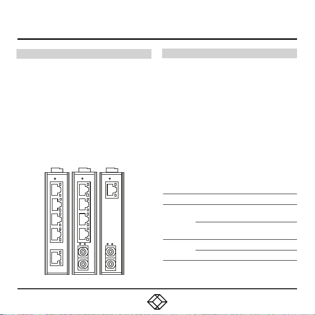
STEP 1 - Hardware Description
INDUSTRIAL MINI SWITCHES
• LBH120A-H (T WISTE D PAIR CONNECTO RS)
• LBH120A-H-S C (SC FIBER CONNECT ORS)
• LBH120A-H-ST (ST FIBER CONNECTORS)
• LBH120A-H-20K-SC (SC FIBER,
20KM DISTANCE)
• LBH120A-H-40K-SC (SC FIB ER,
40 KM DISTANCE)
• LBH120A-H-75K-S C (SC FIBER , 75 KM )
• LBH120A-H-20K-ST (ST FIBER, 20 KM)
LBH120A-H, LBH120A-H-SC, LMC270A-MM-SC
INDUSTRIAL MEDIA CONVERTERS
• LM C270A-MM -SC (SC FIB ER MU LTIMO DE)
• LMC270A-MM-S T (SC FIB ER MU LTIM ODE)
• LM C270A-SM -20K-SC (SC, SI NGLE-MO DE,
20 KM DISTANCE)
• LM C270A-SM -40K-S C (SC, SI NGL E-MODE,
40 KM DISTANCE)
• LM C270A-SM -75K-SC (SC, SINGL E-MODE,
75 KM DISTANCE)
• LMC270A-SM-20K-ST (ST, SINGLE-MODE,
20 KM DISTANCE)
TABLE 2. LED INDICATORS
LED STAT E DESSCRIPTION
Network connection
established
Transmitting or
receiving data
Lin k/Act
100
Steady
Flashing
Steady Transfer at 100 Mbps
Off Transfer at 10 Mbps
Page 3
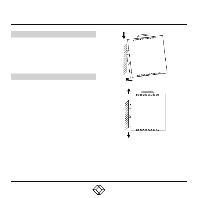
STEP 2 - Install on DIN Rail
INS TALL TH E UN IT ON TH E DIN R AIL
Place the switch o n the DIN rail from above
using the slot. Push the fro nt of the switch
toward th e mounti ng surface until it audibly
snaps into place.
DISMANTLING
Pull ou t the lower edge and then remove
the device from th e DIN rail.
Page 4
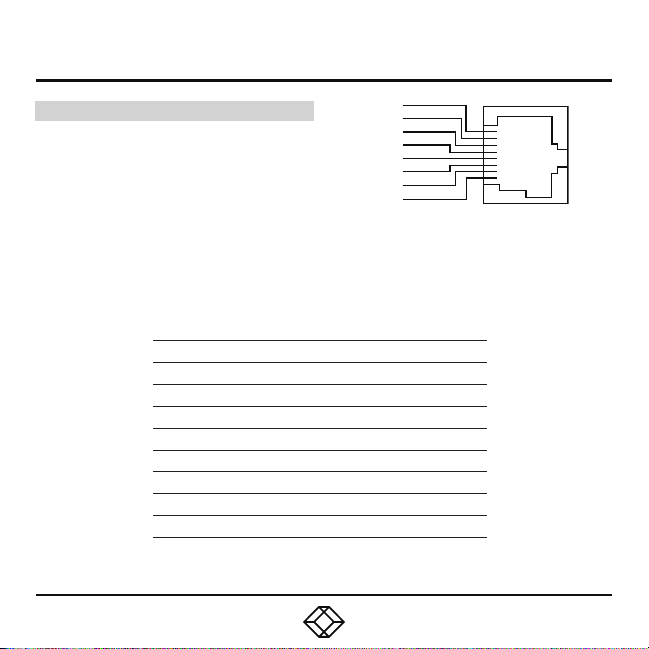
STEP 3A - Connect 10/100BASE-TX
10/100 BAS E-T X C ON NE CT ION S
The tab le below lists the pinouts of the
10/100BA SE-TX ports.The picture at right
shows the connector pinout.
TABLE 1. 10/100BASE-TX PINOUTS
PIN REGULAR PORTS UPLINK PORT
1 Input Receive Data + Output Transmit Data +
2 Input Receive Data - Output Transmit Data -
3 Output Transmit Data + Input Receive Data +
4 Not connected Not connected
5 Not connected Not connected
6 Output Transmit Data - Input Receive Data -
7 Not connected Not connected
8 Not connected Not connected
Pin 8
Pin 7
Pin 6
Pin 5
Pin 4
Pin 3
Pin 2
Pin 1
Page 5
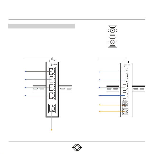
STEP 3B - Connect 100BASE-FX
100BASE-FX CO NNECT IONS
The Tx (trans mit) port of device 1 is connecte d
to the Rx (receive) port of dev ice 2, and the Rx
(receive) port of device 1 to th e Tx (transmit)
port of device 2 . The fiber connector is shown
at right.
POWER
DEVICES
LINK/
ACT
PWR
1
2
3
4
100
LINK/
ACT
5
100
COPPER UPLINK
POWER
DEVICES
FIBER UPLINK
LINK/
ACT
PWR
1
2
3
4
LINK/
100
ACT
X
Page 6
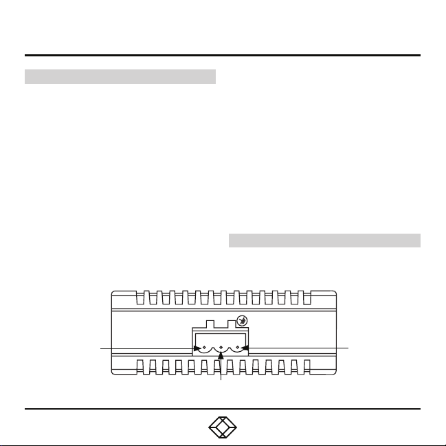
STEP 4 - Connect the Power
GRO UND ING T HE UN IT
CAUTI ON: This equipm ent is des igned to p ermit
the connection of the grounded conductor
of the DC supply circuit to the grounding
conductor at the equipment.
For power connection, the following conditions
must be met:
• This e quipme nt must be connected d irectly
to the DC su pply sys tem grounding electrode
condu ctor or to a bondi ng jumper from a
groun ding terminal bar or bus to which the DC
supply system grounding electrode conductor
is connected.
• This e quipme nt must be located in the same
immediate area (such as, adjacent c abinets)
as any other equipment that has a connectio n
between the grounded conduc tor of the same
PWR
12–48 VDC
POWER INPUT
POWER GROUND
DC supp ly circuit and the grounding cond uctor,
and also the point of grounding of the DC
system. The DC system should not be
grounded elsewhere.
• The DC supply source must be located with in
the same premises as the equ ipment.
• Switching or disconnectin g devices will not be
in the grounded c ircuit conduc tor between the
DC source and the p oint of connection of the
grounding electrode conductor.
STA RTU P
Connect the 12–48 V DC power supply voltag e
to star t up the switch via the terminal block.
GND
GROUND
Page 7
STEP 5 - Download the User Manual (Optional)
OPTIONAL: DOWNLOAD USER MANUAL
For product specific ations and regulatory
information, refer to the U ser Manu al. You can
download this document from our we b site.
1. Go to www.blac kbox.com
2. Ente r the part num ber (LBH120A- H) in the
searc h box.
3. Click on the product in th e “Product
Results” page.
4. Click on the “Support” tab on the product pag e,
and sel ect the docu ment you wish to download .
If you have a ny trouble accessing the Black B ox
site to download th e manual, you can contact
our Technical Sup port at 877- 877-2269
or [email protected]
Page 8

STEP X - Name of Step
COPYRIGHT 2018 BLACK BOX CORPORATION. ALL RIGHTS RESERVED.
 Loading...