

Black Box LMC1017A-SFP, LMC1017AE, LMC1017A-MMST, LMC1017A-MMSC, LMC1017A-SMST User guide [en, es]
...Page 1
FlexPoint™ Triple Speed
10/100/1000 UTP to 100/1000X
Ethernet Media Converter
User Manual
US Power Supplies International Power Supplies
LMC1017A-SFP LMC1017AE
LMC1017A-MMST
LMC1017A-MMSC
LMC1017A-SMST
LMC1017A-SMSC
LMC1017A-SMSC-LH
CUSTOMER
SUPPORT
INFORMATION
Order toll-free in the U.S.: Call 877-877-BBOX
(outside U.S. call 724-746-5500)
FREE technical support 24 hours a day, 7 days a
week; Call 724-746-5500 or fax 724-746-0746
Mailing address: Black Box Corporation,
1000 Park Drive, Lawrence, PA 15055-1018
Web site: www.blackbox.com
E-mail: [email protected]
POWER ADAPTER NOTICE:
1. This product should only be used with Black Box Supplied
Power Unit model numbers PWPB112511 [US] or
LMC203A [Universal].
2. When used in a standalone configuration, this product
must be used with a Listed Direct Plug-In Power Unit
marked “Class 2” and rated at 9VDC, 1 Amp.
NOTE: If mounting with a safety ground attachment,
use the safety ground screw at the rear of the unit.
Page 1 Page 2 Page 3
NOTE: Remove safety ground screw when installing
the module in the 14-Module Chassis or when using
it with the DC-DC Converter (Model # LMC204A)
WARNING!
Before inserting the Power Adapter, verify
that the power on the unit is appropriate
for your AC line voltage source.
INSTALLATION PROCEDURE
1.) Configure the appropriate FlexPoint Triple Speed DIPSwitch settings.
2.) Connect the UTP port via a Category 5 or better cable
to a 10BASE-T, 100BASE-TX or 1000BASE-T Ethernet
device.
3.) When using fixed fiber port models, connect the
appropriate multimode or single-mode fiber cable to the
fiber port of the installed module. It is important to ensure
that the transmit (Tx) is attached to the receive side of the
device at the other end and the receive (Rx) is attached to
the transmit side.
4.) When using the SFP model, insert the SFP Fiber
transceiver into the Port 1 SFP receptacle on the Triple
Speed.
NOTE: The release latch of the SFP Fiber transceiver
must be in the closed (up) position before insertion.
Connect the appropriate multimode or single-mode fiber
cable to the fiber port of the installed module.
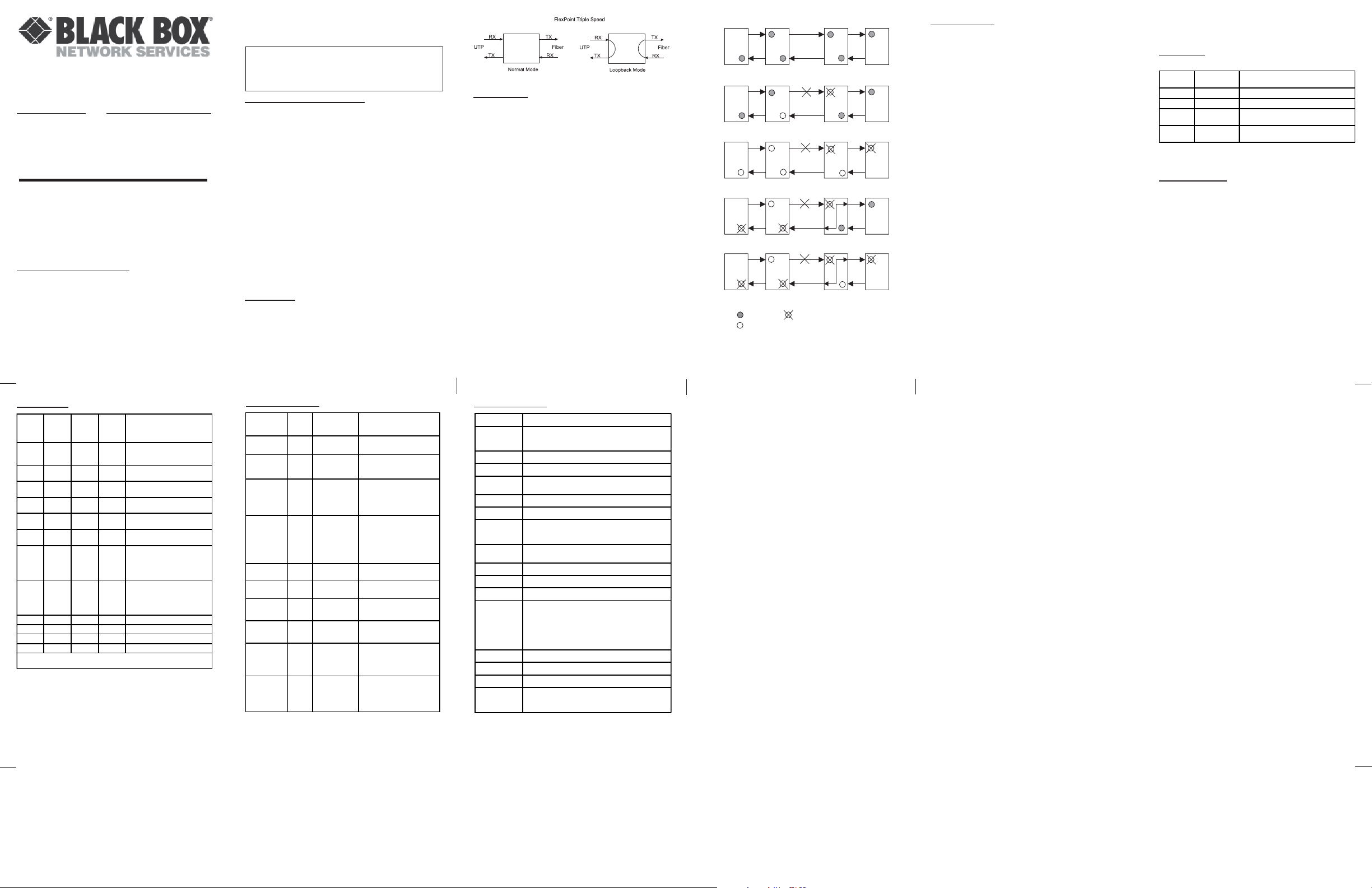
LOOPBACK
The FlexPoint Triple Speed has the capability to provide
loopback to aid in installation and maintenance. A DIPswitch is used to enable loopback on the module (see
page 6). Figure 1 shows the module in normal and loopback
modes.
Figure 1: Loopback Mode
LINK MODES
In order to accommodate different user needs, the Triple
Speed supports four different link modes (see Fig. 2).
In Link Segment (LS), a port transmits a Link signal
independently of any received Link at any other port. For
example, the UTP transmits a Link regardless of the fiber
receiving a Link [Fig. 2(a) & (b)].
In Link Propagate (LP), a port transmits a Link signal only
when receiving a Link at its other port. For example, the
UTP transmits a Link only when receiving a Link at the
fiber port [Fig. 2(c)].
In Remote Fault Detection + Link Segment (RFD+LS),
the fiber port transmits a Link signal only when receiving
a Link at the fiber port. As a result, fiber faults (no Link
received at the fiber) are looped-back and can be reported
to the network core [Fig. 2(d)].
In Remote Fault Detection + Link Propagate (RFD+LP),
the UTP port transmits a Link signal only when receiving
a Link at the fiber port. The fiber port transmits a Link
signal only when receiving Link signals at both the fiber
port and the UTP port. As a result, fiber faults (no Link
received at the fiber) are propagated forward and looped
back for fault reporting at both the network core and the
customer location [Fig. 2(e)].
NOTE: Connecting two converters with both set to RFD
mode is not supported and will cause a “deadly embrace”
lockup.
(a)
LS
UTP
Fiber
Fiber
LS
UTP
Switch 1 Converter A Converter B Switch 2
LS
LS
(b)
Switch 1 Converter A Converter B Switch 2
LP
LP
(c)
Switch 1 Converter A Converter B Switch 2
LP
RFD+LS
(d)
Switch 1 Converter A Converter B Switch 2
LP
RFD+LP
(e)
Switch 1 Converter A Converter B Switch 2
LED On
LED Status depends on connected device
LED Off
Figure 2: Link Modes
Page 4 Page 5 Page 6
DIP-SWITCHES
F/O Manual/Auto “Man/AN” DIP-Switch
Setting this DIP-Switch to Auto-Negotiate “AN” (factory
setting) enables the fiber port to determine duplex mode
automatically.
If the connected device cannot provide the proper signal
to indicate its own mode of operation, set this DIP-Switch
to Manual “MAN.” This feature allows connections with
legacy manual negotiation devices that do not support
auto-negotiation.
NOTE: When the fiber port is configured for Manual
Mode, a link may not occur with the connected device.
Configure both devices to Manual mode to establish
a link.
F/O Speed “100/1000” DIP-Switch:
The Triple Speed supports 100BASE-FX and 1000BASE-X
SFPs. This DIP-switch is used to configure the unit for
the speed of SFP used. Setting this DIP-switch to “1000”
enables the fiber port is accept 1000BASE-X SFPs. Setting
this DIP-switch to “100” enables the fiber port to accept
100BASE-FX SFPs.
UTP Configuration DIP-Switches:
See the UTP Modes table on page 7.
Pause “On/Off” DIP-Switch:
In auto-negotiation mode, setting this DIP-switch to “On”
allows the unit to advertise as Symmetrical and
Asymmetrical Pause capability . In auto-negotiation mode,
setting the DIP-switch to “Off” causes the unit to advertise
no Pause capability. In the manual mode, this DIP-switch
determines the Symmetrical Pause behavior.
Loopback “Off/On” DIP-Switch:
Setting this DIP-switch “On” enables loopback on the
fiber and UTP ports (see Figure 1).
Link Modes:
See the following table for configuring link modes:
SW9
"LS/LP"
LS Normal Enables Link Segment mode (LS).
LP Normal Enables Link Propagate mode (LP).
LS RFD
LP RFD
SW10
"RFD/Normal"
Result
Enables Remo te F a ult Det e ct i on mod e pl us
Link Segment mode (RFD+LS).
Enables Remo te F a ult Det e ct i on mod e pl us
Link Propagation mode (RFD+LP).
NOTE: RFD is only available when the fiber port is
operating in manual mode.
REMOTE FAULT
Each port will generate an “IEEE remote_fault indicator”
when the incoming signal to the port is lost. When a port
is configured for auto-negotiation, it will set the remote
fault bit “high” in the AN advertisement when the port
detects a loss of incoming signal. See LED Indicators
table on page 8 for specifics on how the unit reports the
detection of this signal.
When the fiber port is operating in 100BASE-FX, a loss of
incoming signal will cause the port to generate a Far-EndFault indicator pattern. See LED Indicators table on page
8 for specifics on how the unit reports the detection of
this signal.
UTP MODES
SW3
SW4
SW5
SW6
UTP Mode of Operation
AN/MAN
10/100/
10/100
1000
AN 1000 NA FDX Configured for Auto Negotiation.
AN 1000 NA HDX Configured for Auto Negotiation.
AN 10-100 100 FDX Configured for Auto Negotiation.
AN 10-100 100 HDX Configured for Auto Negotiation.
AN 10-100 10 FDX Configured for Auto Negotiation.
AN 10-100 10 HDX Configured for Auto Negotiation.
MAN 1000 NA FDX Configured for Auto Negotiation.
MAN 1000 NA HDX Configured for Auto Negotiation.
MAN 10-100 100 FDX Port forced to 100 FDX
MAN 10-100 100 HDX Port forced to 100 HDX
MAN 10-100 10 FDX Port forced to 10 FDX
MAN 10-100 10 HDX Port forced to 10 HDX
When the module is co nfig ured fo r a uto-neg otiatio n, the mod ule will a d vertise in
the order shown in the parenthesis.
FDx/HDx
(1000F, 1000H, 100F, 100H, 10F,
10H)
(1000H, 100F, 100H, 10F, 10H)
(100F, 100H, 10F, 10H)
(100H, 10F, 10H)
(10F, 10H)
(10H)
(1000F)
When the port is s e t to 1 0 0 0 , it is
always in AN mode.
(1000H)
When the port is s e t to 1 0 0 0 , it is
always in AN mode.
LED INDICATORS
LED Function
"Legend"
Power / Test
"Power"
F/O AN
"F/O-Auto-Neg"
F/O Speed 100
"F/O-100"
F/O Speed 1000
"F/O-1000"
UTP D uplex
"UTP-FDX"
UTP AN
"UTP-Auto-Neg"
UTP Speed 100
"UTP-100"
UTP Speed 1000
"UTP-1000"
UTP Speed 10
"UTP-100"
+
"UTP-1000"
"UTP Auto-Neg"
+
"UTP-100"
+
"UTP-1000"
Color Off State
Green No power
Green
Green
Green
Green Half-Duplex
Green
Green
Green
Green
Green -
Po rt confi g ure d for
manual negotiation
Not connected at
100Mbps
Not connected at
1000Mbps
Po rt confi g ure d for
manual negotiation
Not connected at
100Mbps
Not connected at
1000Mbps
Not connected at
10Mbps
On / Blinking S tate
On: Module has power
Blinking: Module in loo pback
mode
On: Fiber port configured for AN
Blinking: Fiber port co nfigured for
AN but e stablishe li nk i n manual
mode
On: Fiber port linked at 100Mbps
Blinking (10Hz): Li nk activity at
100Mbps
Blink in g (1 H z ): Signal detected
but port unable to establish a link
On: Fiber port linked at 1000Mbps
Blinking (10Hz): Li nk activity at
1000Mbps
Blink in g (1 H z ): Signal detected
but port unable to establish a link
Pattern Blinking: AN remote Fault
bit detected
On: UTP port in Full-Duplex
On: UTP port configured for AN
Blinking: UTP p o rt confi gured for
AN but in manual mode
On: UTP port linked at 100Mbps
Blinking (10Hz): Li nk activity
On: UTP port linked at 1000Mbps
Blinking (10Hz): Li nk activity
On: UTP port linked at 10Mbps
Blinking (10Hz): Li nk activity
Pattern Blinking: Detecting
"remote_fault" (AN) on UTP port
Blink in g (1 H z ): Unab le to establish
AN link on the UTP port
SPECIFICATIONS
Model Type Triple Speed
Protocols
Frame Size
UTP Cable
Fiber Cables
UTP Connectors
Fiber Connectors
DIP-Switches
LED Displays
Dimensions
Weight
Compliance**
Power
Requirements
Temperature
Humidity
Altitude
MTBF (Hours)
10BASE-T, 100BASE-TX, 1000BASE-T, 100BASE-FX,
UTP: Auto-Neg, 10, 100, 1000, FDX/HDX, Pause En/Dis
Loopback, Link Seg, Link Prop, Remote Fault Det.
Power, Fiber AN, Fiber Speed/Activity, UTP Speed/Activity,
Nominal Voltage:
Voltage Range:
Nominal Power:
Maximum Pow e r :
Module without Power Adapter: 900,000
Module with Power Adapter -1: 250,000
Module with Power Adapter -2: 100,000
IEEE 802.3
1000BASE-X
10,240 byte max. frame size
RJ-45, Category 5 and higher
Multimode: 50/125, 62.5/125, 100/140µm
Single-mode: 9/125µm
RJ-45
LC (SF P ), S C , S T
Fiber: Auto-Neg, 1000, 100
Full/Half-Duplex
W: 3.0" x D: 4.0" x H: 1.0"
6 oz. (without power adapter)
UL, CE, FCC Class A
Barrel
Connector
9VDC
5.0 to 32.0VDC
0.3A @ 9VDC
1A @ 9VDC
0 to 50
5 to 95% (non-condensing)
-100m to 4000m
o
C
Molex
Connector
5VDC
5.0 to 32.0VDC
0.5A @ 5VDC
0.75A @ 5VDC
TRADEMARKS
All applied-for and registered trademarks are the property
of their respective owners.
FEDERAL COMMUNICA TIONS COMMISSION AND
CANADIAN DEPAR TMENT OF COMMUNICA TIONS
RADIO FREQUENCY INTERFERENCE ST A TEMENTS
This equipment generates, uses, and can radiate radio
frequency energy and if not installed and used properly, that
is, in strict accordance with the manufacturer’s instructions,
may cause interference to radio communication. It has been
tested and found to comply with the limits for a Class A
computing device in accordance with the specifications in
subpart J of Part 15 of FCC rules, which are designed to
provide reasonable protection against such interference when
the equipment is operated in a commercial environment.
Operation of this equipment in a residential area is likely to
be cause interference, in which case the user at his own
expense will be required to take whatever measures may be
necessary to correct the interference.
Changes or modifications not expressly approved by the party
responsible for compliance could void the user’s authority
to operate the equipment.
This digital apparatus does not exceed the Class A limits
for radio noise emission from digital apparatus set out in
the Radio Interference Regulation of the Canadian
Department of Communications.
Le présent appareil numérique n’émet pas de bruits
radioélectriques dépassant les limites applicables aux
appareils numéirques de las classe A prescrites dans le
Règlement sur le brouillage radioélectrique publié par le
ministère des Communications du Canada.
NORMAS OFICIALES MEXICANAS (NOM)
1. Todas las instrucciones de seguridad y operación deberán
ELECTRICAL SAFETY STA TEMENT
ser leídas antes de que el aparato eléctrico sea operado.
2. Las instrucciones de seguridad y operación deberán ser
guardadas para referencia futura.
3. Todas las advertencias en el aparato eléctrico y en sus
instrucciones de operación deben ser respetadas.
4. Todas las instrucciones de operación y uso deben ser seguidas.
5. El aparato eléctrico no deberá ser usado cerca del agua—
por ejemplo, cerca de la tina de baño, lavabo, sótano
mojado o cerca de una alberca, etc.
6. El aparato eléctrico debe ser usado únicamente con carritos
o pedelstales que sean recomendados por el fabricante.
7. El aparato eléctrico debe ser montado a la pared o al techo
sólo como sea recomendado por el fabricante.
8. Servicio—El usuario no debe intentar dar servicio al
equipo eléctrico más allá a lo descrito en las instrucciones
de operación. Todo otro servicio deberá ser referido a
personal de servicio calificado.
9. El aparato eléctrico debe ser situado de tal manera que su
posición no interfiera su uso. La colocación del aparato
eléctrico sobre una cama, sofá, alfombra or superficie
similar puede bloquea la ventilación, no se debe colocar
en libreros o gabinetes que impidan el flujo de aire por
los orificios de ventilación.
10. El equipo eléctrico deber ser situado fuera del alcance de
fuentes de calor como radiadores, registros de calor,
estufas u ostros aparatos (incluyendo amplificadores) que
producen calor.
11. El aparato eléctrico deberá ser connectado a una fuente
de poder sólo del tipo descrito en el instructivo de
operación, o como se indique en el aparato.
12. Precación debe ser tomada de tal manera que la tierra fisica y la
polarización del equipo no sea eliminada.
13. Los cables de la fuente de poder deben ser guiados de tal manera
que no sean pisados ni pellizcados por objetos colocados sobre o
contra ellos, poniendo particular atención a los contactos y
receptáculos donde salen del aparato.
14. El equipo eléctrico debe ser limpiado únicamente de acuerdo a
las recomendaciones del fabricante.
15. En caso de existir, una antena externa deberá ser localizada lejos
de las lineas de energia.
16. El cable de corriente deberá ser desconectado del cuando el
equipo no sea usado por un largo periodo de tiempo.
17. Cuidado debe ser tomado de tal manera que objectos liquidos no
sean derramados sobre la cubierta u orificios de ventilación.
18. Servicio por personal calificado deberá ser provisto cuando:
A: El cable de poder o el contacto ha sido dañado; u
B: Objectos han caído o líquido ha sido derramado dentro del
aparato; o
C: El aparato ha sido expuesto a la lluvia; o
D: El aparato parece no operar normalmente o muestra un
cambio en su desempeño; o
E: El aparto ha sido tirado o su cubierta ha sido dañada.
Page 7
Page 8
Page 9
Page 10 Page 11
Form: 040-L1017-001C 1/11
Page 12
Page 2
UTP MODES
SW3
SW4
SW5
SW6
UTP Mode of Operation
AN/MAN
10/100/
10/100
1000
AN 1000 NA FDX Config ure d fo r A uto Ne g o tiation.
AN 1000 NA HDX C o nfigured for Auto Neg o tiation.
AN 10-1 00 100 FDX Configured for Auto Negotiation.
AN 10-1 00 100 HDX Co nfigured for Auto Neg o tiation.
AN 10-1 00 1 0 FDX Configured fo r Auto Negotia tion.
AN 10-1 00 1 0 HDX Configured for Auto Neg o tiation.
MAN 100 0 NA FDX Confi gured for Auto Nego tiation.
MAN 100 0 NA HD X C o nfigured for Auto Neg o tiation.
MAN 10-100 100 FDX Port forced to 100 FDX
MAN 10-100 100 HDX Port forced to 100 HDX
MAN 10-100 10 FDX Port forced to 10 FDX
MAN 10-100 10 HDX Port forced to 10 HDX
When the module is co nfig ured for auto-negotia tion, the module will adverti se in
the order shown in the parenthesis.
FDx/HDx
(1000F, 1000H, 100F, 100H, 10F,
10H)
(1000H, 100F, 100H, 10F, 10H)
(100F, 100H, 10F, 10H)
(100H, 10F, 10H)
(10F, 10H)
(10H)
(1000F)
When the port is set to 1000, it is
always in AN mode.
(1000H)
When the port is set to 1000, it is
always in AN mode.
LED INDICATORS
LED Function
"Legend"
Power / Test
"Power"
F/O AN
"F/O-Auto-Neg"
F/O Speed 100
"F/O-100"
F/O Speed 1000
"F/O-1000"
UTP Duplex
"UTP-FDX"
UTP AN
"UTP-Auto-Neg"
UTP Speed 100
"UTP-100"
UTP Speed 1000
"UTP-1000"
UTP Speed 10
"UTP-100"
+
"UTP-1000"
"UTP Auto-Neg"
+
"UTP-100"
+
"UTP-1000"
Color Off State
Green No power
Green
Green
Green
Green Half-Duplex
Green
Green
Green
Green
Green -
Port config ured for
manual negotiation
Not connected at
100Mbps
Not connected at
1000Mbps
Port config ured for
manual negotiation
Not connected at
100Mbps
Not connected at
1000Mbps
Not connected at
10Mbps
On / Blinking State
On: Module has power
Blinking: Module in loopback
mode
On: Fiber port configured for AN
Blinking: Fiber port configured for
AN but establishe link in manual
mode
On: Fiber port linked at 100Mbps
Blinking (10Hz): Link acti vity at
100Mbps
Blinking (1Hz): Signal detected
but port unable to establish a link
On: Fiber port linked at 1000Mbps
Blinking (10Hz): Link acti vity at
1000Mbps
Blinking (1Hz): Signal detected
but port unable to establish a link
Pattern Blinking: AN remote Fault
bit detected
On: UTP port in Full-Duplex
On: UTP port configur ed fo r A N
Blinking: UTP port configured for
AN but in manual mode
On: UTP port linked at 100Mbps
Blinking (10Hz): Link acti vity
On: UTP port linked at 1000Mbps
Blinking (10Hz): Link acti vity
On: UTP port linked at 10Mbps
Blinking (10Hz): Link acti vity
Pattern Blinking: Detecting
"remote_fault" (AN) on UTP port
Blinking (1Hz): Unable to establish
AN link on the UTP port
SPECIFICATIONS
Model Type Triple Speed
Protocols
Frame Size
UTP Cable
Fiber Cables
UTP Connectors
Fiber Connectors
DIP-Switches
LED Displays
Dimensions
Weight
Compliance**
Power
Requirements
Temperature
Humidity
Altitude
MTBF (Hours)
10BASE-T, 100BASE-TX, 1000BASE-T, 100BASE-FX,
UTP: Auto-Neg, 10, 100, 1000, FDX/HDX, Pause En/Dis
Loopback, Link Seg, Link Prop, Remote Fault Det.
Power, Fiber AN, Fiber Speed/Activity, UTP Speed/Activity,
Nominal Voltage:
Voltage Range:
Nominal Power:
Maximum Pow e r :
Module without Power Adapter: 900,000
Module with Power Adapter -1: 250,000
Module with Power Adapter -2: 100,000
IEEE 802.3
1000BASE-X
10,240 byte max. frame size
RJ-45, Category 5 and higher
Multimode: 50/125, 62.5/125, 100/140µm
Single-mode: 9/125µm
RJ-45
LC (SF P ), S C , S T
Fiber: Auto-Neg, 1000, 100
Full/Half-Duplex
W: 3.0" x D: 4.0" x H: 1.0"
6 oz. (without power adapter)
UL, CE, FCC Class A
Barrel
Connector
9VDC
5.0 to 32.0VDC
0.3A @ 9VDC
1A @ 9VDC
0 to 50
5 to 95% (non-condensing)
-100m to 4000m
o
C
Molex
Connector
5VDC
5.0 to 32.0VDC
0.5A @ 5VDC
0.75A @ 5VDC
TRADEMARKS
All applied-for and registered trademarks are the property
of their respective owners.
FEDERAL COMMUNICA TIONS COMMISSION AND
CANADIAN DEPAR TMENT OF COMMUNICA TIONS
RADIO FREQUENCY INTERFERENCE ST A TEMENTS
This equipment generates, uses, and can radiate radio
frequency energy and if not installed and used properly, that
is, in strict accordance with the manufacturer’s instructions,
may cause interference to radio communication. It has been
tested and found to comply with the limits for a Class A
computing device in accordance with the specifications in
subpart J of Part 15 of FCC rules, which are designed to
provide reasonable protection against such interference when
the equipment is operated in a commercial environment.
Operation of this equipment in a residential area is likely to
be cause interference, in which case the user at his own
expense will be required to take whatever measures may be
necessary to correct the interference.
Changes or modifications not expressly approved by the party
responsible for compliance could void the user’s authority
to operate the equipment.
This digital apparatus does not exceed the Class A limits
for radio noise emission from digital apparatus set out in
the Radio Interference Regulation of the Canadian
Department of Communications.
Le présent appareil numérique n’émet pas de bruits
radioélectriques dépassant les limites applicables aux
appareils numéirques de las classe A prescrites dans le
Règlement sur le brouillage radioélectrique publié par le
ministère des Communications du Canada.
NORMAS OFICIALES MEXICANAS (NOM)
1. Todas las instrucciones de seguridad y operación deberán
ELECTRICAL SAFETY STATEMENT
ser leídas antes de que el aparato eléctrico sea operado.
2. Las instrucciones de seguridad y operación deberán ser
guardadas para referencia futura.
3. Todas las advertencias en el aparato eléctrico y en sus
instrucciones de operación deben ser respetadas.
4. Todas las instrucciones de operación y uso deben ser seguidas.
5. El aparato eléctrico no deberá ser usado cerca del agua—
por ejemplo, cerca de la tina de baño, lavabo, sótano
mojado o cerca de una alberca, etc.
6. El aparato eléctrico debe ser usado únicamente con carritos
o pedelstales que sean recomendados por el fabricante.
7. El aparato eléctrico debe ser montado a la pared o al techo
sólo como sea recomendado por el fabricante.
8. Servicio—El usuario no debe intentar dar servicio al
equipo eléctrico más allá a lo descrito en las instrucciones
de operación. Todo otro servicio deberá ser referido a
personal de servicio calificado.
9. El aparato eléctrico debe ser situado de tal manera que su
posición no interfiera su uso. La colocación del aparato
eléctrico sobre una cama, sofá, alfombra or superficie
similar puede bloquea la ventilación, no se debe colocar
en libreros o gabinetes que impidan el flujo de aire por
los orificios de ventilación.
10. El equipo eléctrico deber ser situado fuera del alcance de
fuentes de calor como radiadores, registros de calor,
estufas u ostros aparatos (incluyendo amplificadores) que
producen calor.
11. El aparato eléctrico deberá ser connectado a una fuente
de poder sólo del tipo descrito en el instructivo de
operación, o como se indique en el aparato.
12. Precación debe ser tomada de tal manera que la tierra fisica y la
polarización del equipo no sea eliminada.
13. Los cables de la fuente de poder deben ser guiados de tal manera
que no sean pisados ni pellizcados por objetos colocados sobre o
contra ellos, poniendo particular atención a los contactos y
receptáculos donde salen del aparato.
14. El equipo eléctrico debe ser limpiado únicamente de acuerdo a
las recomendaciones del fabricante.
15. En caso de existir, una antena externa deberá ser localizada lejos
de las lineas de energia.
16. El cable de corriente deberá ser desconectado del cuando el
equipo no sea usado por un largo periodo de tiempo.
17. Cuidado debe ser tomado de tal manera que objectos liquidos no
sean derramados sobre la cubierta u orificios de ventilación.
18. Servicio por personal calificado deberá ser provisto cuando:
A: El cable de poder o el contacto ha sido dañado; u
B: Objectos han caído o líquido ha sido derramado dentro del
aparato; o
C: El aparato ha sido expuesto a la lluvia; o
D: El aparato parece no operar normalmente o muestra un
cambio en su desempeño; o
E: El aparto ha sido tirado o su cubierta ha sido dañada.
Page 7
FlexPoint™ Triple Speed
10/100/1000 UTP to 100/1000X
Ethernet Media Converter
User Manual
US Power Supplies International Power Supplies
LMC1017A-SFP LMC1017AE
LMC1017A-MMST
LMC1017A-MMSC
LMC1017A-SMST
LMC1017A-SMSC
LMC1017A-SMSC-LH
CUSTOMER
SUPPORT
INFORMATION
Order toll-free in the U.S.: Call 877-877-BBOX
(outside U.S. call 724-746-5500)
FREE technical support 24 hours a day, 7 days a
week; Call 724-746-5500 or fax 724-746-0746
Mailing address: Black Box Corporation,
1000 Park Drive, Lawrence, PA 15055-1018
Web site: www.blackbox.com
E-mail: [email protected]
POWER ADAPTER NOTICE:
1. This product should only be used with Black Box Supplied
Power Unit model numbers PWPB112511 [US] or
LMC203A [Universal].
2. When used in a standalone configuration, this product
must be used with a Listed Direct Plug-In Power Unit
marked “Class 2” and rated at 9VDC, 1 Amp.
NOTE: If mounting with a safety ground attachment,
use the safety ground screw at the rear of the unit.
Page 1 Page 2 Page 3
Page 8
NOTE: Remove safety ground screw when installing
the module in the 14-Module Chassis or when using
it with the DC-DC Converter (Model # LMC204A)
WARNING!
Before inserting the Power Adapter, verify
that the power on the unit is appropriate
for your AC line voltage source.
INSTALLATION PROCEDURE
1.) Configure the appropriate FlexPoint Triple Speed DIPSwitch settings.
2.) Connect the UTP port via a Category 5 or better cable
to a 10BASE-T, 100BASE-TX or 1000BASE-T Ethernet
device.
3.) When using fixed fiber port models, connect the
appropriate multimode or single-mode fiber cable to the
fiber port of the installed module. It is important to ensure
that the transmit (Tx) is attached to the receive side of the
device at the other end and the receive (Rx) is attached to
the transmit side.
4.) When using the SFP model, insert the SFP Fiber
transceiver into the Port 1 SFP receptacle on the Triple
Speed.
NOTE: The release latch of the SFP Fiber transceiver
must be in the closed (up) position before insertion.
Connect the appropriate multimode or single-mode fiber
cable to the fiber port of the installed module.
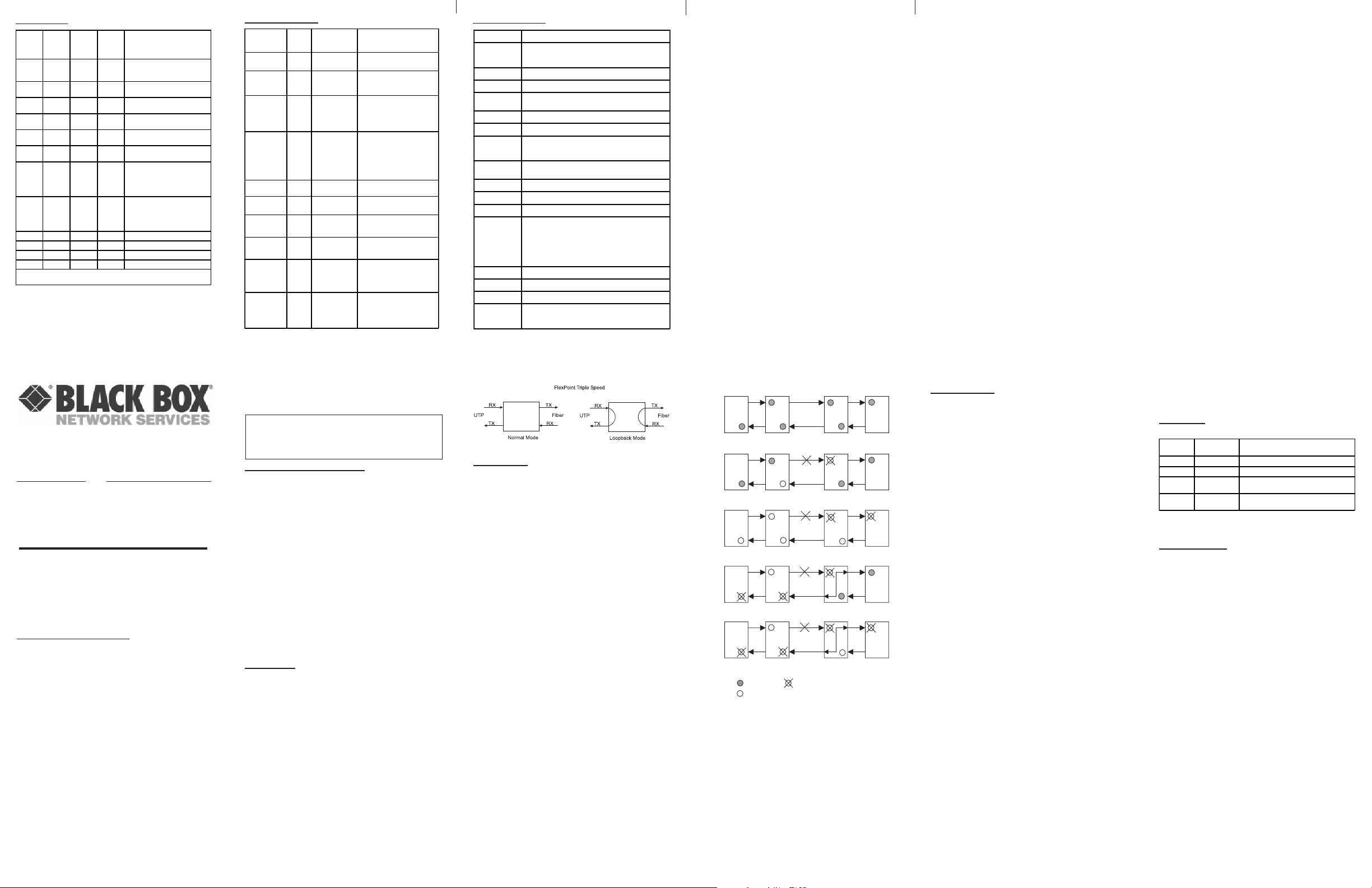
LOOPBACK
The FlexPoint Triple Speed has the capability to provide
loopback to aid in installation and maintenance. A DIPswitch is used to enable loopback on the module (see
page 6). Figure 1 shows the module in normal and loopback
modes.
Page 9
Figure 1: Loopback Mode
LINK MODES
In order to accommodate different user needs, the Triple
Speed supports four different link modes (see Fig. 2).
In Link Segment (LS), a port transmits a Link signal
independently of any received Link at any other port. For
example, the UTP transmits a Link regardless of the fiber
receiving a Link [Fig. 2(a) & (b)].
In Link Propagate (LP), a port transmits a Link signal only
when receiving a Link at its other port. For example, the
UTP transmits a Link only when receiving a Link at the
fiber port [Fig. 2(c)].
In Remote Fault Detection + Link Segment (RFD+LS),
the fiber port transmits a Link signal only when receiving
a Link at the fiber port. As a result, fiber faults (no Link
received at the fiber) are looped-back and can be reported
to the network core [Fig. 2(d)].
In Remote Fault Detection + Link Propagate (RFD+LP),
the UTP port transmits a Link signal only when receiving
a Link at the fiber port. The fiber port transmits a Link
signal only when receiving Link signals at both the fiber
port and the UTP port. As a result, fiber faults (no Link
received at the fiber) are propagated forward and looped
back for fault reporting at both the network core and the
customer location [Fig. 2(e)].
NOTE: Connecting two converters with both set to RFD
mode is not supported and will cause a “deadly embrace”
lockup.
Page 10 Page 11
LS
(a)
UTP
Switch 1 Converter A Converter B Switch 2
LS
Fiber
Fiber
LS
UTP
LS
(b)
Switch 1 Converter A Converter B Switch 2
LP
LP
(c)
Switch 1 Converter A Converter B Switch 2
LP
RFD+LS
(d)
Switch 1 Converter A Converter B Switch 2
LP
RFD+LP
(e)
Switch 1 Converter A Converter B Switch 2
LED On
LED Status depends on connected device
LED Off
Figure 2: Link Modes
Page 4 Page 5 Page 6
DIP-SWITCHES
F/O Manual/Auto “Man/AN” DIP-Switch
Setting this DIP-Switch to Auto-Negotiate “AN” (factory
setting) enables the fiber port to determine duplex mode
automatically.
If the connected device cannot provide the proper signal
to indicate its own mode of operation, set this DIP-Switch
to Manual “MAN.” This feature allows connections with
legacy manual negotiation devices that do not support
auto-negotiation.
NOTE: When the fiber port is configured for Manual
Mode, a link may not occur with the connected device.
Configure both devices to Manual mode to establish
a link.
F/O Speed “100/1000” DIP-Switch:
The Triple Speed supports 100BASE-FX and 1000BASE-X
SFPs. This DIP-switch is used to configure the unit for
the speed of SFP used. Setting this DIP-switch to “1000”
enables the fiber port is accept 1000BASE-X SFPs. Setting
this DIP-switch to “100” enables the fiber port to accept
100BASE-FX SFPs.
UTP Configuration DIP-Switches:
See the UTP Modes table on page 7.
Pause “On/Off” DIP-Switch:
In auto-negotiation mode, setting this DIP-switch to “On”
allows the unit to advertise as Symmetrical and
Asymmetrical Pause capability . In auto-negotiation mode,
setting the DIP-switch to “Off” causes the unit to advertise
no Pause capability. In the manual mode, this DIP-switch
determines the Symmetrical Pause behavior.
Form: 040-L1017-001C 1/11
Page 12
Loopback “Off/On” DIP-Switch:
Setting this DIP-switch “On” enables loopback on the
fiber and UTP ports (see Figure 1).
Link Modes:
See the following table for configuring link modes:
SW9
"LS/LP"
LS Normal Enables Link Segment mode (LS).
LP Normal E nables Link Propagate mode (LP).
LS RFD
LP RFD
SW10
"RFD/Normal"
Result
Enables Remo te Fault Detecti o n mod e plus
Link Segment mode (RFD+LS).
Enables Remo te Fault Detecti o n mod e plus
Link Propagation mode (RFD+LP).
NOTE: RFD is only available when the fiber port is
operating in manual mode.
REMOTE FAULT
Each port will generate an “IEEE remote_fault indicator”
when the incoming signal to the port is lost. When a port
is configured for auto-negotiation, it will set the remote
fault bit “high” in the AN advertisement when the port
detects a loss of incoming signal. See LED Indicators
table on page 8 for specifics on how the unit reports the
detection of this signal.
When the fiber port is operating in 100BASE-FX, a loss of
incoming signal will cause the port to generate a Far-EndFault indicator pattern. See LED Indicators table on page
8 for specifics on how the unit reports the detection of
this signal.
 Loading...