

Page 1
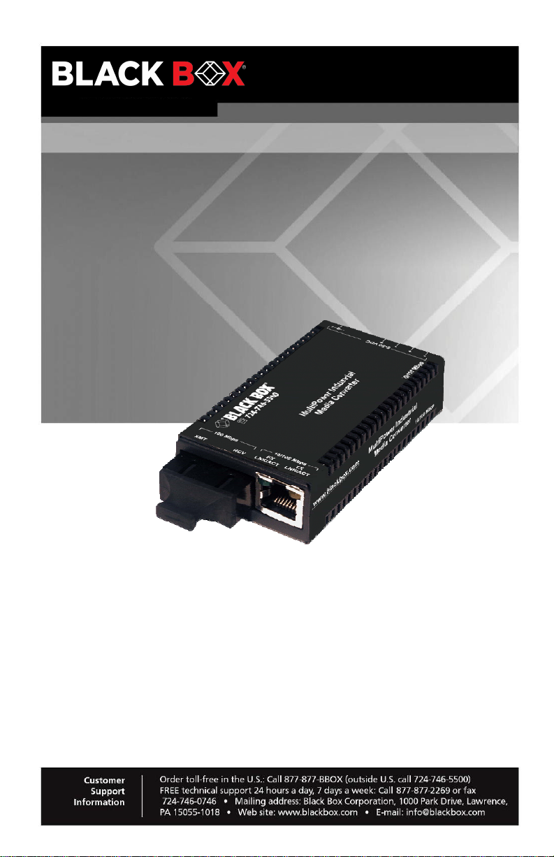
LIC022A-R3 LIC025A-R3
LIC023A-R3 LIC026A-R3
LIC024A-R3
MultiPower Industrial Media Converters
Choose from four different ways
to power these hardened media converters.
Page 2

TRADEMARKS USED IN THIS MANUAL
B
lack Box and the Black Box logo type and mark are registered trademarks
of BB Technologies, Inc.
Any other trademarks mentioned in this manual are acknowledged to be the
property of the trademark owners.
Page 2 877-877-2269 | blackbox.com
Page 3

FCC and IC RFI Statements
FCC and Industry Canada RF Interference Statements
Class A (using DC terminal power or Power over Ethernet (PoE). This
equipment has been tested and found to comply with the limits for a Class B
computing device pursuant to Part 15 of the FCC Rules. These limits are
designed to provide reasonable protection against harmful interference in a
residential installation. However, there is no guarantee that interference will not
occur in a particular installation. This equipment generates, uses, and can
radiate radio frequency energy, and, if not installed and used in accordance with
the instructions, may cause harmful interference to radio communications. If this
equipment does cause harmful interference to radio or telephone reception,
which can be determined by turning the equipment off and on, the user is
encouraged to try to correct the interference by one of t he following measures:
•
Reorient or relocate the rec
• Increase the separation between the equipment and receiver.
• Connect the
the receiver is connected.
• Consult an experi
equipment into an outlet on a circuit different from that to which
enced radio/TV technician for help.
eiving antenna.
Class B (using any DC jack options). . This equipment has been
found to comply with the limits for a Class B computing device pursuant to Part
15 of the FCC Rules. These limits are designed to provide reasonable protection
against harmful interference in a residential installation. However, there is no
guarantee that interference will not occur in a particular installation. This
equipment generates, uses, and can radiate radio frequency energy, and, if not
installed and used in accordance with the instructions, may cause harmful
interference to radio communications. If this equipment does cause harmful
interference to radio or telephone reception, which can be determined by turning
the equipment off and on, the user is encouraged to try to correct the
interference by one of the foll owing measures:
•
Reorient or relocate the rec
• Increase the separation between the equipment and receiver.
• Connect the
the receiver is connected.
• Consult an experi
CAUTION
Changes o
compliance could void the user’s authority to operate the equipment.
equipment into an outlet on a circuit different from that to which
enced radio/TV technician for help.
r modifications not expressly approved by the party responsible for
eiving antenna.
tested and
To meet FCC requirements, shielded cables and power cords are required to
connect this device to a personal computer or other Class B certified device.
This digital apparatus does not exceed the Class B limits for radio noise
emission from digital apparatus set out in the Radio Interference Regulation
of Industry Canada.
877-877-2269 | blackbox.com Page 3
Page 4
Certifications
Certifications
Class 1 Laser product, Luokan 1 Laserlaite,
Laser Klasse 1, Appareil A’Laser de Classe
European Directive 2002/96/EC (WEEE) requires that any equipment that
bears this symbol on product or packaging must not be disposed of with
unsorted municipal waste. This symbol indicates that the equipment should
be disposed of separately from regular household waste. It is the
consumer’s responsibility to dispose of this and all equipment so marked
through designated collection facilities appointed by government or local
authorities. Following these steps through proper disposal and recycling will
help prevent potential negative consequences to the environment and
human health. For more detailed information about proper disposal, please
contact local authorities, waste disposal services, or the point of purchase for
this equipment.
Page 4 877-877-2269 | blackbox.com
Page 5

Table of Contents
Table of Contents
Part Numbers......................................................................................................6
1. Specifications.........................................................................................7
2. Overview: About the MultiPower Industrial Media Converters..............8
3. Install the MultiPower Industrial Media Converters................................9
3.1 DIN Rail Mounting..................................................................................9
3.2 Cascading DC Power.............................................................................9
3.3 Powering the MultiPower Industrial Media Converters........................10
3.4 About Power over Ethernet (PoE) and MultiPower Industrial Media
Converters............................................................................................10
3.5 DC Terminal Block Wiring Instructions.................................................10
4. Operation..............................................................................................11
5. Contacting Black Box...........................................................................12
6. Fiber Optic Cleaning Guidelines ..........................................................13
7. Electrostatic Discharge Precautions ....................................................14
877-877-2269 | blackbox.com Page 5
Page 6

Part Numbers
Part Numbers
Part
Number
LIC022A-R3
LIC023A-R3
LIC024A-R3
LIC025A-R3
LIC026A-R3
Description
TP-TX/FX-MM1300-ST (5 km)
TP-TX/FX-MM1300-SC (5 km)
TP-TX/FX-SM1310/PLUS-ST (30 km)
TP-TX/FX-SM1310/PLUS-SC (30 km)
TP-TX/FX-SM1310/LONG-ST (80 km)
Page 6 877-877-2269 | blackbox.com
Page 7

1. Specifications
Chapter 1: Specifications
Ethernet Connections
DC terminal 7 to 50 VDC, 1 to0.1A
DC (jack) 5 VDC
PoE When MultiPower Industri
AC Wall Adapter 100 to 240 ±10% VAC input, 5 VDC output,
Power Consumption
(Typical)
Operating Temperature
DC configurations -13°F to +185°F (-25°C to +85°C)
With AC wall adapter +14°F to +122°F (-10°C to +50°C)
Storage Temperature -40°F to +185°F (-40°C to +85°C)
Humidity 5% to 95% (non-condensing)
Dimensions 0.83"Hx1.80"Wx3.35"D (2.11x4.57x8.51 cm)
• 10/100 BaseT
• Auto Negotiation
• Auto-Cross
• Flow Control
• 1916 MTU
R
• Full Line-
use PoE technology to be a PD, the maximum
supply voltage is 50V
2A max.
500mA @ 5 VDC
ate Forwarding
al Media Converters
NOTE: The media converters are now compliant to EN62368.
877-877-2269 | blackbox.com Page 7
Page 8

Chapter 2: Overview
2. Overview: About the MultiPower Industrial Media Converters
The MultiPower Industrial Media Conve
between 10/100 Base-T twisted pair and 100 Base-SX/FX fiber. This device
Auto Negotiates speed and duplex on the copper port and the fiber is
100Mbps, FDX. The unit supports jumbo frames up to 1916 MTU.
The MultiPower Industrial Media Converters are fixed fiber transceiver
models that include one 10/100 Mbps RJ-45 connector and one 10/100
Mbps SC fiber connector which can support Single Mode fiber or Multi Mode
fiber in Dual Strand or Single Strand fiber.
The MultiPower Industrial Media Converters are Industrial Ethernet devices
which allows for extended temperature operation of -25ºC to +85ºC for DC
power, or (-10ºC to +50ºC when using the AC adapter). When installing the
MultiPower Industrial Media Converters in an 18 slot tray or using DC power,
the temperature range supported is -13°F to +185°F (-25°F to +85°F).
rters provide a single conversion
Page 8 877-877-2269 | blackbox.com
Page 9
Chapter 3: Install the MultiPower Industrial Media Converters
3. Install the MultiPower Industrial Media Converters
The MultiPower Industrial Media Converters install virtually anywhere as
standalone devices in locations with extremely limited space. Installation
options include:
• Velcro strips
• DIN rail mo
• PowerTray/18 for high de
3.1 DIN Rail Mounting
unting with DIN Rail clips
nsity applications
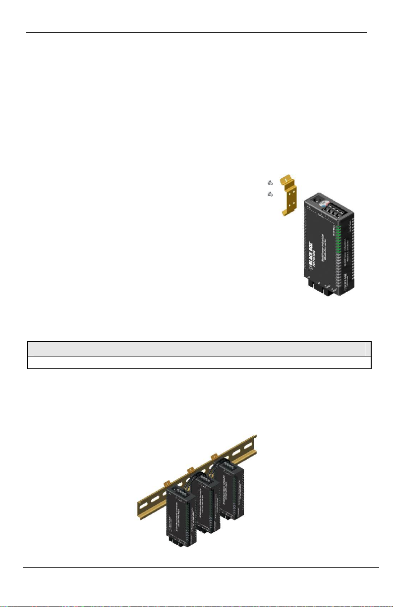
The MultiPower Industrial Media Converters
ship
from the factory with DIN clips, allowing installation
on a DIN rail. Depending on the installation, the
MultiPower Industrial Media Converters can be
mounted parallel or perpendicular to the DIN rail.
Use the supplied screws to attach the DIN clips to
the MultiPower Industrial Media Converters, and
then snap the converter to the DIN rail.
To remove the converter from the DIN rail, use a
flat-head screwdriver in the slot to gently pry the
converter from the rail.
NOTE
The DIN clips are designed for use on a DIN-35 rail.
3.2 Cascading DC Power
When installing multiple MultiPower Industrial Media Converters on a DIN
rail, the end user can connect to one DC input source, and then cascade
from one DC block to the next, until reaching the maximum current available.
877-877-2269 | blackbox.com Page 9
Page 10
Chapter 3: Install the MultiPower Industrial Media Converters
3.3 Powering the MultiPower Industrial Media Converters
The MultiPower Industrial Media Converters include multiple powering
options:
•
A country-specific, high-reliability AC pow
• The IEEE 802.3af Po
wer over Ethernet standard; draws power from
power sourcing equipment
• The 4-
• IE PowerTray 18-Slot AC fo
terminal DC power block
r Rack Mounting
• USB cable
• IE-5V DIN rail
mount Power Supply
er adapter (included)
3.4 About Power over Ethernet (PoE) and MultiPo
wer Industrial Media
Converters
Power over Ethernet technology allows the MultiPower Industrial Media
Converters to be Powered Devices (PD) and draw power when connected to
Power Sourcing Equipment (PSE). Power Sourcing Equipment distributes
an electrical current across existing copper data cabling.
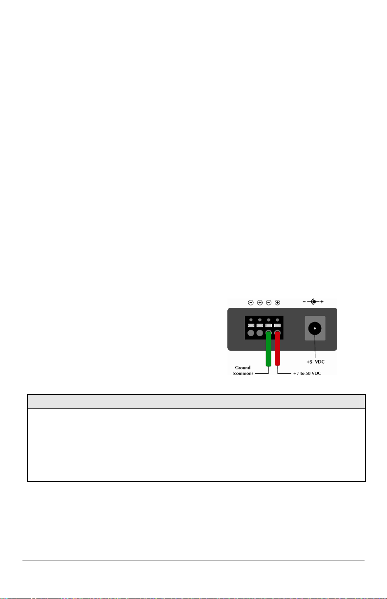
3.5 DC Terminal Block Wiring Instructions
The MultiPower Industrial Media
Converters can also be powered with
the DC terminal block. From a power
source, connect to any one positive
and any one negative terminal on the
MultiPower Industrial Media
Converters.
NOTE
When using stranded wire, the leads must be tinned and equivalent to a 16 AWG solid
conductor. The DC terminal block is protected against mis-wiring. If the unit is miswired, positive power lead to the negative terminal and negative power lead to the
positive terminal, it will not function. When powering a unit with voltages near the
upper limit of the device’s specification (for example: 48 volts) take precautions to limit
the voltage at the units terminal block. When tur nin g on h i gh volt a ge DC circ uits , initial
voltages may momentarily exceed the unit’s specification.
Page 10 877-877-2269 | blackbox.com
Page 11
4. Operation
Chapter 4: Operation
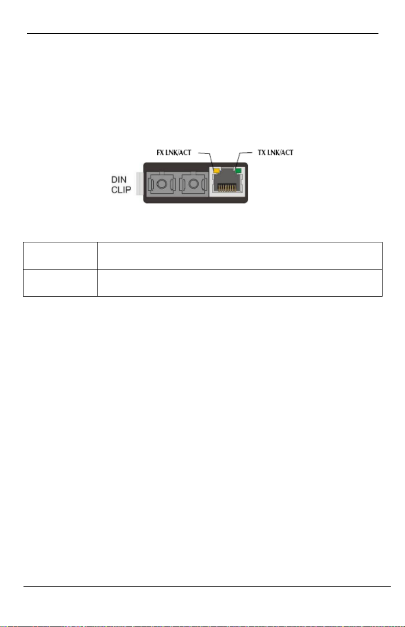
The MultiPower Industrial Media Converters
the RJ-45 connector.
LED functions are as follows:
LED functions are as follows (above illustration is representative):
FX LNK/ACT Glows green when a link is established on the fiber port;
blinks green when activity is detected on the fiber port.
TX LNK/ACT Glows amber when a link is established on the copper port;
blinks amber when activity is detected on the copper port.
include two LEDs, located on
877-877-2269 | blackbox.com Page 11
Page 12

Chapter 5: Contacting Black Box
5. Contacting Black Box
Black Box Customer Service
Order toll-f
Free technical support, 24 hours a day, 7 days a week.
Mail order: Black Box Corporation
Web site: www.blackbox.com
E-mail: [email protected]
ree in the U.S.: Call 877-877-BBOX
(outside U.S. call 724-746-5500)
Call: 877-877-2269 or Fax: 724-746-0746
1000 Park Drive, Lawrence, PA 15055-1018
om
Page 12 877-877-2269 | blackbox.com
Page 13

Chapter 6: Fiber Optic Cleaning Guidelines
6. Fiber Optic Cleaning Guidelines
Fiber Optic transmitters and receivers are extremely susceptible to
contamination by particles of dir
and cause performance degradation. Good system performance requires
clean optics and connector ferrules.
1. Use fiber patch cords (or connectors, if you terminate your own fiber) only
from a reputable supplier; low-quality components can cause many
diagnose problems in an installation.
2. Dust caps are installed at Black Box to ensur
These protective caps should not be remo
the fiber cable to the device. If you need to disconnect the fiber device,
reinstall the protective dus t caps.
3. Store spare caps in a dust-free env ironment
box so that when reinstalle
optics.
4. If you suspect that the optics have been contami
blasting with clean, dry, compressed air and flushing with methanol to remove
particles of dir
t.
t or dust, which can obstruct the optic path
hard-to-
e factory-clean optical devices.
ved until the m oment of connecting
uch as a sealed plastic bag or
s
d they do not introduce any contamination to the
nated, alternate between
877-877-2269 | blackbox.com Page 13
Page 14

Chapter 7: Electrostatic Discharge Precautions
7. Electrostatic Discharge Precautions
Electrostatic discharge (ESD) can cause damage to any product, add-in
modules or stand alone units, containing electronic components. Always
observe the following precautions when installing or handling these kinds of
products.
1. Do not remove unit from its protective packaging until ready to install.
2. Wear an ESD wrist grounding strap before handling any module or
component. If the wrist strap is not available, maintain grounded contact with
the system unit throughout any procedure requiring ESD protec
Hold the units by the edges; do not touch the electronic components or gold
3.
connectors.
4. After removal, always place the boards on a grounded, static-free surface,
ESD pad or in a proper ESD bag. Do not slide the modules or stand alone
units over any surface.
WARNING! Integrated circuits and fiber optic components
are extremely susceptible to electrostatic discharge damage.
Do not handle these components directly unless you are a
qualified service technician and use tools and techniques that
conform to accepted industry practices.
tion.
Page 14
877-877-2269 | blackbox.com
Page 15

Notes
877-877-2269 | blackbox.com Page 15
Page 16

Black Box Tech Support: FREE! Live. 24/7.
Tech support the
way it should be.
Great tech support is just 60 seconds away at 877-877-2269 or
blackbox.com.
About Black Box
Black Box® is a trusted IT solutions provider delivering cutting-edge technology products and world-class
consulting services to businesses across the globe in every industry. The breadth of our global reach and depth
of our expertise accelerate customer success by bringing people, ideas, and technology together to solve realworld business problems.
© Copyright 2022. Black Box Corporation. All rights reserved. Black Box® and the Black Box logo type and mark are registered trademarks
of BB Technologies, Inc. Any third-party trademarks appearing in this manual are acknowledged to be the property of their respective
owners.
LIC022A-R3_user_Rev1.pdf
877-877-2269 | blackbox.com
 Loading...