

Page 1

USER MANUAL
LHC210A, LHC211A, LHC212A, LGC210A, LGC211A, LGC212A, LHGC-RACK
MEDIA
CONVERTERS
AND CHASSIS
24/7 TECHNICAL SUPPORT AT 1.877.877.2269 OR VISIT BLACKBOX.COM
Page 2

NEED HELP?
LEAV E TH E TEC H TO US
LIVE 24/7
TABLE OF CONTENTS
TECHNICAL
SUPPORT
1. 8 7 7. 8 7 7. 2 2 69
1. SPECIFICATIONS ...................................................................................................................................................................................... 3
2. OVERVIE W ................................................................................................................................................................................................. 4
2.1 Introduction .......................................................................................................................................................................................................... 4
2.2 Features ............................................................................................................................................................................................................... 4
2.3 What’s Included ................................................................................................................................................................................................... 4
2.4 Hardware Description ......................................................................................................................................................................................... 5
2.4.1 LHC210A ...........................................................................................................................................................................................................................5
2.4.2 LHC211A ...........................................................................................................................................................................................................................6
2.4.3 LHC212A ..........................................................................................................................................................................................................................7
2.4.4 LGC210A ........................................................................................................................................................................................................................... 8
2.4 . 5 LGC211A ...........................................................................................................................................................................................................................9
2.4.6 LGC 212A .........................................................................................................................................................................................................................10
2.4.7 LHGC-RACK ...................................................................................................................................................................................................................11
2.5 Application Diagram ......................................................................................................................................................................................... 12
3. INSTALLING THE CONVERTERS........................................................................................................................................................... 13
3.1 Initial Steps for Standalone or Rackmount Installation ................................................................................................................................. 13
3.1.1 Install the SFP Module in the SFP Cage (LHC210A and LGC210A Only) ...........................................................................................................13
3.1.2 Set the DIP Switches (LHC210A, LHC211A and LHC212A Only) ........................................................................................................................13
3.2 Installing the Converter as a Standalone Unit ................................................................................................................................................ 15
3.2.1 Connect the Media Cables (LHC210A, LHC211A, LHC212A, LGC210A, LGC211A, LGC212A) ....................................................................15
3.3 Installing the Media Converters in the 14-Slot Chassis ................................................................................................................................. 15
3.3.1 Install the Chassis in a 19" Cabinet or Rack ............................................................................................................................................................15
3.3.2 Plug the Media Converters into the Chassis Slots.................................................................................................................................................15
3.3.3 Connect the Network Cables .....................................................................................................................................................................................15
3.4 Installation Diagram .......................................................................................................................................................................................... 16
4. MAINTENANCE AND TROUBLESHOOTING ......................................................................................................................................... 17
4.1 Maintenance ...................................................................................................................................................................................................... 17
4.1.1 Finding Out the Problems ............................................................................................................................................................................................17
4.1.2 Replacing the Power Supply .......................................................................................................................................................................................17
4.2 Troubleshooting ................................................................................................................................................................................................ 17
APPENDIX A: REGULATORY INFORMATION ........................................................................................................................................... 18
A.1 FCC Statement .................................................................................................................................................................................................. 18
A.2 NOM Statement ................................................................................................................................................................................................ 19
APPENDIX B: DISCLAIMER/TRADEMARKS ............................................................................................................................................ 20
B.1 Disclaimer .......................................................................................................................................................................................................... 20
B.2 Trademarks Used in this Manual ..................................................................................................................................................................... 20
2
1. 87 7. 8 7 7. 2 26 9 BL ACK BOX .COM
Page 3

CHAPTER 1: SPECIFICATIONS
TABLE 1-1. CHASSIS SPECIFICATIONS
SPECIFICATION DESCRIPTION
Number of Slots 14
Compatible Media Converters
Media Supported
Connectors
Power
Temperature
Relative Humidity
Dimensions
Weight 15.4 lb. (7.0 kg)
Mounting Comes with blanks and mounting hardware for 14 converters
LHC210A, LHC211A, LHC212A, LGC210A, LGC211A, LGC212A
10/100/1000BASE-T twisted pair and 10/100/1000BASE-FX fiber optic cable
Depends on media converters installed
Dual Power supplies included: (1) LHGC-RACK-PS-L and (1) LHGC-RACK-PS-R;
Input: 100-240 VAC, 50/60 Hz, 3.0 A;
Output: 5 VDC, 12 A, 60 W;
Connector: IEC320 C14 on each power supply;
Circuit breaker for overvoltage or short circuit protection
Operating: 32 to 122° F (0 to 50° C);
Storage: -4 to 185° F (-20 to +85° C)
5 to 95%, noncondensing
3.5” H (2U) x 19” W x 9.1" D (8.9 x 48.2 x 23.1 cm)
NEED HELP?
LEAV E TH E TEC H TO US
LIVE 24/7
TECHNICAL
SUPPORT
1. 8 7 7. 8 7 7. 2 2 69
TABLE 1-2. MEDIA CONVERTERS SPECIFICATIONS
SPECIFICATION DESCRIPTION
Approvals FCC Class B, CE, RoHS
Standards
Media Supported
Connectors
User Controls
Maximum Distance
NIC Transmission Rate
Optical Port Transmission Rate
Optical Connector Wavelength
Power
Temperature
Relative Humidity
Dimensions
LHC210A , LHC211A, LHC212A: 10/100BAS E-TX , 100BASE- F X;
LGC210A: LGC211A, LGC212A: 10/100BASE-TX/1000BASE-TX, 1000BASE-FX
10/100/1000BASE-T: CAT5 UTP/STP, max. 328 ft. (100 m);
100/1000BASE-FX
All: (1) RJ-45,
LHC210A, LGC210A: (1) SFP slot;
LHC211A, LGC211A: (1) MM SC;
LHC212A, LGC212A: (1) SM SC;
LHC210A. LHC211A, LHC212A: (2) 4-position DIP switches
LHC210A, LGC210A: Depends on SFP installed;
LHC211A: 1.2 mi. (2 km) over multimode fiber optic cable:
LHC212A: 12.4 mi. (20 km) over single-mode fiber optic cable;
LGC211A: 1640 ft. (500 m) over multimode fiber optic cable;
LGC212A: 6.2 mi. (10 km) over single-mode fiber optic cable
LHC210A, LHC211A, LHC212A: 10/100 Mbps, auto MDI/MDI-X;
LGC210A, LGC211A, LGC212A: 10/100/1000 Mbps, auto MDI/MDI-X
LHC210A, LHC211A, LHC212A: 100 Mbps;
LGC210A, LGC211A, LGC212A: 1000 Mbps
LHC210A, LGC210A: Depends on SFP installed;
LHC211A, LHC212A, LGC212A; 1310 nm:
LGC211A: 850 nm
All: 5 VDC;
LHC210A, LHC211A, LHC212A: <1 W;
LGC210A, LGC211A, LGC212A: <3 W
Operating: 32 to 122° F (0 to 50° C);
Storage: -4 to 158° F (-20 to +70° C)
5 to 90%, noncondensing
Each unit: 1" H x 3.7" W x 2.7" D (2.5 x 9.4 x 6.9 cm)
C210A,
1. 87 7. 8 7 7. 2 26 9 BL ACK BOX .COM
3
Page 4

NEED HELP?
LEAV E TH E TEC H TO US
LIVE 24/7
CHAPTER 2: OVERVIEW
TECHNICAL
SUPPORT
1. 8 7 7. 8 7 7. 2 2 69
2.1 INTRODUCTION
The 10/100 and 10/100/1000 Media Converters support three types of media for network connection, including 10/100BASE-T and
10/100/1000BASE-T for twisted-pair connection and 1000BASE-FX for single-mode or multimode fiber connection. The chassis
can hold up to 14 media converters.
2.2 FEATURES
Complies with IEEE 802.3 10/100BASE-TX, 10/100/1000BASE-TX and 1000BASE-TX standards
Each media converter has one RJ-45 twisted-pair port and one MM or SM SC port or SFP module slot
Twisted-pair port supports auto-adaption rate and full/half-duplex mode, as well as auto MDI/MDI-X
Six LEDs indicate optical power and twisted-pair port status
Chassis includes a built in power supply and Media Converters come with an external power supply which will not be used
if they are going to be used in the chassis
Optional 2U chassis holds up to 14 media converters for convenient mounting in a 19" rack or cabinet
2.3 WHAT’S INCLUDED
Before you start installing the Converter, verify that the package contains the following:
LHC210A, LHC211A, LHC212A, LGC210A, LGC211A or LGC212A:
The TP- Fiber Converter
5-VDC Power Adapter
LHGC-RACK:
(2) Power supplies
(14) Rackmount brackets
If anything is missing or damaged, contact Black Box Technical Support at 877-877-2269 or info@blackbox.com
4
1. 87 7. 8 7 7. 2 26 9 BL ACK BOX .COM
Page 5
NEED HELP?
LEAV E TH E TEC H TO US
LIVE 24/7
CHAPTER 2: OVERVIEW
TECHNICAL
SUPPORT
1. 8 7 7. 8 7 7. 2 2 69
2.4 HARDWARE DESCRIPTION
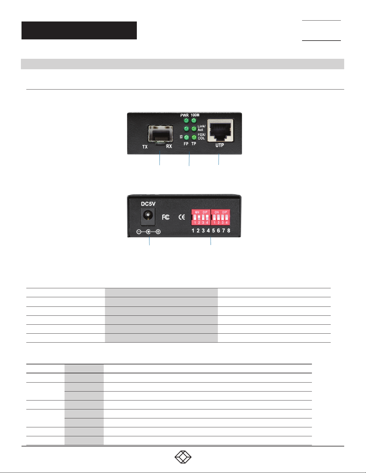
2.4 .1 L HC 210 A
Figures 2-1 and 2-2 show the front and back panels of the LHC210A converter. Tables 2-1 and 2-2 describe its components.
1 2 3
FIGURE 2-1. LHC210A FRONT PANEL
4 5
FIGURE 2-2. LHC210A BACK PANEL
TABLE 2-1. LHC210A MEDIA CONVERTER COMPONENTS
NUMBER IN FIGURE 2-1 OR 2-2 COMPONENT DESCRIPTION
1 SFP cage SFP module installs here
2
3
4
5
LED indicators
RJ-45 connector
Barrel connector for power
(2) 4-position DIP switches, numbered 1–8 See Table 3-2
See Table 2-2
Links to RJ-45 cable
Links to 47–57-VDC power supply
TABLE 2-2. LHC210A LED INDICATORS
LED NAME STAT U S DESCRIPTION
PWR ON Power is ON and normal
FX Link/ACT
SD
100M
TX Link/Act
TX FDX/COL
ON
Blinking
ON
ON
OFF Link is operating at 10 Mbps
ON
Blinking
Connection Status display for fiber link. ON indicates that the fiber link is correctly connected
Packet is being transmitted through the FX end
Fiber signal is detected
Link is operating at 100 Mbps
Connection status display for copper link. ON indicates that the link is correctly connected
Active status display of copper link. Packet is being transmitted through the TX end
1. 87 7. 8 7 7. 2 26 9 BL ACK BOX .COM
5
Page 6

NEED HELP?
LEAV E TH E TEC H TO US
LIVE 24/7
CHAPTER 2: OVERVIEW
TECHNICAL
SUPPORT
1. 8 7 7. 8 7 7. 2 2 69
2.4.2 LH C211A
Figures 2-3 and 2-4 show the front and back panels of the LHC211A converter. Tables 2-3 and 2-4 describe its components.
1 2 3
FIGURE 2-3. LHC211A FRONT PANEL
4 5
FIGURE 2-4. LHC211A BACK PANEL
TABLE 2-3. LHC211A MEDIA CONVERTER COMPONENTS
NUMBER IN FIGURE 2-3 OR 2-4 COMPONENT DESCRIPTION
1 MM 1310 Fiber SC connectors Links to 1310 MM Fiber cable
2
3
4
5
LED indicators
RJ-45 connector
Barrel connector for power
(2) 4-position DIP switches, numbered 1–8 See Table 3-2
See Table 2-4
Links to RJ-45 cable
Links to 47–57-VDC power supply
TABLE 2-4. LHC211A LED INDICATORS
LED NAME STAT U S DESCRIPTION
PWR ON Power is ON and normal
FX Link/ACT
SD
100M
TX Link/Act
TX FDX/COL
ON
Blinking
ON
ON
OFF Link is operating at 10 Mbps
ON
Blinking
Connection Status display for fiber link. ON indicates that the fiber link is correctly connected
Packet is being transmitted through the FX end
Fiber signal is detected
Link is operating at 100 Mbps
Connection status display for copper link. ON indicates that the link is correctly connected
Active status display of copper link. Packet is being transmitted through the TX end
6
1. 87 7. 8 7 7. 2 26 9 BL ACK BOX .COM
Page 7

NEED HELP?
LEAV E TH E TEC H TO US
LIVE 24/7
CHAPTER 2: OVERVIEW
TECHNICAL
SUPPORT
1. 8 7 7. 8 7 7. 2 2 69
2.4.3 L HC212A
Figures 2-5 and 2-6 show the front and back panels of the LHC212A converter. Tables 2-5 and 2-6 describe its components.
1 2 3
FIGURE 2-5. LHC212A FRONT PANEL
4 5
FIGURE 2-6. LHC212A BACK PANEL
TABLE 2-5. LHC212A MEDIA CONVERTER COMPONENTS
NUMBER IN FIGURE 2-5 OR 2-6 COMPONENT DESCRIPTION
1 SM 1310 Fiber SC connectors Links to 1310 SM Fiber cable
2
3
4
5
LED indicators
RJ-45 connector
Barrel connector for power
(2) 4-position DIP switches, numbered 1–8 See Table 3-2
See Table 2-6
Links to RJ-45 cable
Links to 47–57-VDC power supply
TABLE 2-6. LHC212A LED INDICATORS
LED NAME STAT U S DESCRIPTION
PWR ON Power is ON and normal
FX Link/ACT
SD
100M
TX Link/Act
TX FDX/COL
ON
Blinking
ON
ON
OFF Link is operating at 10 Mbps
ON
Blinking
Connection Status display for fiber link. ON indicates that the fiber link is correctly connected
Packet is being transmitted through the FX end
Fiber signal is detected
Link is operating at 100 Mbps
Connection status display for copper link. ON indicates that the link is correctly connected
Active status display of copper link. Packet is being transmitted through the TX end
1. 87 7. 8 7 7. 2 26 9 BL ACK BOX .COM
7
Page 8

NEED HELP?
LEAV E TH E TEC H TO US
LIVE 24/7
CHAPTER 2: OVERVIEW
TECHNICAL
SUPPORT
1. 8 7 7. 8 7 7. 2 2 69
2.4.4 LGC210A
Figures 2-7 and 2-8 show the front and back panels of the LGC210A converter. Tables 2-7 and 2-8 describe its components.
1 2 3
FIGURE 2-7. LGC210A FRONT PANEL
4
FIGURE 2-8. LGC210A BACK PANEL
TABLE 2-7. LGC210A MEDIA CONVERTER COMPONENTS
NUMBER IN FIGURE 2-7 OR 2-8 COMPONENT DESCRIPTION
1 SFP cage SFP module installs here
2
3
4
LED indicators
RJ-45 connector
Barrel connector for power
See Table 2-8
Links to RJ-45 cable
Links to 47–57-VDC power supply
TABLE 2-8. LGC210A LED INDICATORS
LED NAME STAT U S DESCRIPTION
PWR ON Power is ON and normal
FX Link/ACT
SD
1000M
TX Link/Act
TX FDX/COL
ON
Blinking
ON
ON
OFF Link is operating at 10/100 Mbps
ON
Blinking
Connection Status display for fiber link. ON indicates that the fiber link is correctly connected
Packet is being transmitted through the FX end
Fiber signal is detected
Link is operating at 1000 Mbps
Connection status display for copper link. ON indicates that the link is correctly connected
Active status display of copper link. Packet is being transmitted through the TX end
8
1. 87 7. 8 7 7. 2 26 9 BL ACK BOX .COM
Page 9

NEED HELP?
LEAV E TH E TEC H TO US
LIVE 24/7
CHAPTER 2: OVERVIEW
TECHNICAL
SUPPORT
1. 8 7 7. 8 7 7. 2 2 69
2.4.5 L GC 211A
Figures 2-9 and 2-10 show the front and back panels of the LGC211A converter. Tables 2-9 and 2-10 describe its components.
1 2 3
FIGURE 2-9. LGC211A FRONT PANEL
4
FIGURE 2-10. LGC211A BACK PANEL
TABLE 2-9. LGC211A MEDIA CONVERTER COMPONENTS
NUMBER IN FIGURE 2-9 OR 2-10 COMPONENT DESCRIPTION
1 MM 850 Fiber SC connectors Links to 850 MM Fiber cable
2
3
4
LED indicators
RJ-45 connector
Barrel connector for power
See Table 2-10
Links to RJ-45 cable
Links to 47–57-VDC power supply
TABLE 2-10. LGC211A LED INDICATORS
LED NAME STAT U S DESCRIPTION
PWR ON Power is ON and normal
FX Link/ACT
SD
1000M
TX Link/Act
TX FDX/COL
ON
Blinking
ON
ON
OFF Link is operating at 10/100 Mbps
ON
Blinking
Connection Status display for fiber link. ON indicates that the fiber link is correctly connected
Packet is being transmitted through the FX end
Fiber signal is detected
Link is operating at 1000 Mbps
Connection status display for copper link. ON indicates that the link is correctly connected
Active status display of copper link. Packet is being transmitted through the TX end
1. 87 7. 8 7 7. 2 26 9 BL ACK BOX .COM
9
Page 10

NEED HELP?
LEAV E TH E TEC H TO US
LIVE 24/7
CHAPTER 2: OVERVIEW
TECHNICAL
SUPPORT
1. 8 7 7. 8 7 7. 2 2 69
2.4.6 LGC 212 A
Figures 2-11 and 2-12 show the front and back panels of the LGC212A converter. Tables 2-11 and 2-12 describe its components.
1 2 3
FIGURE 2-11. LGC212A FRONT PANEL
4
FIGURE 2-12. LGC212A BACK PANEL
TABLE 2-11. LGC212A MEDIA CONVERTER COMPONENTS
NUMBER IN FIGURE 2-11 OR 2-12 COMPONENT DESCRIPTION
1 SM 1310 Fiber SC connectors Links to 1310 SM Fiber cable
2
3
4
LED indicators
RJ-45 connector
Barrel connector for power
See Table 2-12
Links to RJ-45 cable
Links to 47–57-VDC power supply
TABLE 2-12. LGC212A LED INDICATORS
LED NAME STAT U S DESCRIPTION
PWR ON Power is ON and normal
FX Link/ACT
SD
1000M
TX Link/Act
TX FDX/COL
ON
Blinking
ON
ON
OFF Link is operating at 10/100 Mbps
ON
Blinking
Connection Status display for fiber link. ON indicates that the fiber link is correctly connected
Packet is being transmitted through the FX end
Fiber signal is detected
Link is operating at 1000 Mbps
Connection status display for copper link. ON indicates that the link is correctly connected
Active status display of copper link. Packet is being transmitted through the TX end
10
1. 87 7. 8 7 7. 2 26 9 BL ACK BOX .COM
Page 11

NEED HELP?
LEAV E TH E TEC H TO US
LIVE 24/7
CHAPTER 2: OVERVIEW
TECHNICAL
SUPPORT
1. 8 7 7. 8 7 7. 2 2 69
2.4.7 LHGC-RACK
Figure 2-13 shows the front of the rackmount chassis with media converters and blank slot covers installed. Figure 2-14 shows the
back of the rackmount chassis. Table 2-13 describes its components.
1 2 3
FIGURE 2-13. LHGC-RACK, FRONT VIEW
4 5 4 5
FIGURE 2-14. LHGC-RACK, BACK VIEW
TABLE 2-13. MEDIA CONVERTER CHASSIS COMPONENTS
NUMBER IN FIGURE 2-12 OR 2-14 COMPONENT DESCRIPTION
1 Blank slot cover SFP module installs here
2
3
4
5
Media Converter
Rackmount ears
3-prong outlet
ON/OFF switch
Media Converter installs here
Attaches to 19" rack or cabinet
Links to power cord
Turns power ON or OFF
1. 87 7. 8 7 7. 2 26 9 BL ACK BOX .COM
11
Page 12

CHAPTER 2: OVERVIEW
2.5 APPLICATION DIAGRAM
NEED HELP?
LEAV E TH E TEC H TO US
LIVE 24/7
TECHNICAL
SUPPORT
1. 8 7 7. 8 7 7. 2 2 69
FIBER
INTERNET
MEDIA CONVERTER
MEDIA
CONVERTER
MULTI-WA
BROADBAND ROUTER
FIGURE 2-15 APPLICATION DIAGRAM
SWITCH
COMPUTER
12
1. 87 7. 8 7 7. 2 26 9 BL ACK BOX .COM
Page 13

CHAPTER 3: INSTALLING THE CONVERTER
3.1 INITIAL STEPS FOR STANDALONE OR RACKMOUNT INSTALLATION
3.1.1 INSTALL THE SFP MODULE IN THE SFP CAGE (LHC210A AND LGC210A ONLY)
Gently insert a compatible SFP module in the SFP cage on the LHC210A or LGC210A media converter.
See the table below for a list of compatible SFP modules.
TABLE 3-1. COMPATIBLE SFP MODULES (INSTALL IN LHC210A OR LGC210A ONLY)
NEED HELP?
LEAV E TH E TEC H TO US
LIVE 24/7
TECHNICAL
SUPPORT
1. 8 7 7. 8 7 7. 2 2 69
PRODUCT CODE DESCRIPTION
LFP4 01
LFP402
LFP4 03
LFP4 04
LFP411
LF P412
LF P413
LFP414
LFP418
LFP420, LFP421
LFP416
NOTE: LFP420, LFP421 are single-strand fiber SFPs, so they must be used in pairs.
NOTE: Use the LFP416 for a copper interface.
SFP - 155-Mbps, Extended Diagnostics, 850-nm Multimode Fiber, 2-km, LC
SFP - 155-Mbps, Extended Diagnostics, 1310-nm Multimode Fiber, 2-km, LC
SFP - 155-Mbps, Extended Diagnostics, 1310-nm Single-Mode Fiber, 30-km, LC
SFP - 155-Mbps, Extended Diagnostics, 1310-nm Single-Mode Fiber, 60-km, LC
SFP - 1250-Mbps, Extended Diagnostics, 850-nm Multimode Fiber, 550-m, LC
SFP - 1250-Mbps, Extended Diagnostics, 1310-nm Multimode Fiber, 2- km, LC
SFP - 1250-Mbps, Extended Diagnostics, 1310-nm Single- Mode Fiber, 10-km, LC
SFP - 1250-Mbps, Extended Diagnostics, 1310-nm Single- Mode Fiber, 30-km, LC
SFP - 1250-Mbps, Extended Diagnostics, 1550 -nm Single-Mode Fiber, 80-km, LC
SFP - 1250-Mbps, Extended Diagnostics, 1550 -nm TX, 1310- nm RX, Simplex, Single-Mode Fiber, 10-km, LC;
SFP - 1250-Mbps, Extended Diagnostics, 1310-nm TX, 1550- nm RX, Simplex Single-Mode Fiber, 10-km, LC
SFP - 1250-Mbps, Extended Diagnostics, 10/100/1000BASE-T, SGMII Interface, RJ-45
COMPATIBLE MEDIA
CONVERTER
LHC210A
LHC210A
LHC210A
LHC210A
LGC 210A
LGC 210A
LGC 210A
LGC 210A
LGC 210A
LGC 210A
LGC 210A
3.1.2 SET THE DIP SWITCHES (LHC210A, LHC211A AND LHC212A ONLY)
The LHC210A, LHC211A and LHC212A have an 8-position DIP switch, shown in Figure 3-1. The DIP switch functions are described
in Table 3-2.
FIGURE 3-1. DIP SWITCH ON THE LHC210A, LHC211A AND LHC212A
1. 87 7. 8 7 7. 2 26 9 BL ACK BOX .COM
13
Page 14

CHAPTER 3: INSTALLING THE CONVERTER
TA TABLE 3-2. LHC210A, LHC211A AND LHC212A DIP SWITCH SETTINGS BLE
NEED HELP?
LEAV E TH E TEC H TO US
LIVE 24/7
TECHNICAL
SUPPORT
1. 8 7 7. 8 7 7. 2 2 69
DIP SWITCH POSITIONS
1 2 3 4 5 6 7 8
ON
OFF
—
OFF ON OFF ON ON OFF OFF OFF Jumbo enabled
—
—
—
— — — — — — —
— — — —
— — — —
— — —
— — —
— — —
— — —
— — —
— — —
— — —
— — —
— — — — — — —
— — — — — — —
OFF OFF
OFF ON
ON OFF
ON ON
— — — — —
— — — — —
— — — — —
— — — — —
OFF
OFF
OFF
OFF
ON
ON
ON
ON
OFF
ON
—
—
—
—
—
—
—
—
— — —
— — —
OFF OFF
OFF ON
ON OFF
ON OFF
OFF OFF
OFF ON
ON OFF
ON ON
OFF Force fiber port to full-duplex mode
—
—
—
—
—
—
—
—
DESCRIPTION
LFP enabled
LFP disabled
Store and Forward
Modified cut-through switch mode enabled
Converter mode enabled
Auto–change–forward enabled
IEEE 802.3x enabled
IEEE 802.3x disabled
Force TX port to 10M/100M full duplex/half-duplex with autonegotiation
Force TX port to 10M/100M half-duplex with auto-negotiation
Force TX port to 10M full duplex/half-duplex with auto-negotiation
Force TX port to 10M half-duplex with auto-negotiation
Force TX port to 100M full duplex with auto-negotiation
Force TX port to 100M half-duplex with auto-negotiation
Force TX port to 10M full duplex with auto-negotiation
Force TX port to 10M half-duplex with auto-negotiation
14
1. 87 7. 8 7 7. 2 26 9 BL ACK BOX .COM
Page 15

NEED HELP?
LEAV E TH E TEC H TO US
LIVE 24/7
CHAPTER 3: INSTALLING THE CONVERTER
TECHNICAL
SUPPORT
1. 8 7 7. 8 7 7. 2 2 69
3.2 INSTALLING THE CONVERTER AS A STANDALONE UNIT
3.2.1 CONNECT THE MEDIA CABLES (LHC210A, LHC211A, LHC212A, LGC210A, LGC211A, LGC212A)
1. Verify that the AC-DC adapter conforms to your country’s AC power requirement and insert the power plug.
2. Connect the media cable for network connection.
2a. For the fiber port, the TX/RX fiber cable must be paired at both ends. The default setting for the converter is full-duplex mode.
2b. For the twisted-pair port, attach the CAT5 twisted-pair cable to the RJ-45 port on the converter.
3.3 INSTALLING THE CONVERTERS IN THE 14-SLOT CHASSIS
The 14-slot media converter chassis supports plug-and-play installation of up to 14 table-top media converters. The chassis can
supply several media converters with power.
You can hot-swap the media converters in and out of the chassis. The chassis works with a single power supply or dual power
supplies, depending on your power requirements.
3.3.1 INSTALL THE CHASSIS IN A 19" CABINET OR RACK
Install the media converter chassis in a standard 19" rack or cabinet and secure it with screws (not included).
3.3.2 PLUG THE MEDIA CONVERTERS INTO THE CHASSIS SLOTS
1. Unscrew the two screws next to the RJ-45 port of the first media converter. Use these two screws to affix the media converter to
the chassis.
2. Insert the media converter in to the chassis, making sure the power plug of the chassis is inserted in the power port of the media
converter. WHen the converter is fully and firmly fitted to the chassis, fasten the screws on the chassis.
3. Repeat steps 1 and 2 for the remaining media converters you want to install.
3.3.3 CONNECT THE NETWORK CABLES
1. Insert the RJ-45 twisted-pair cable into the RJ-45 port on the converter, and insert the fiber cable into the fiber port on the
converter.
2. Connect the supplied AC power cable to the receptacle at the back of the chassis, attach the plug to a standard 100 to 260 VAC
outlet.
3. Turn the power switch ON and the Power LEDs on the front of the chassis will light green.
4. Turn on both power supplies. This extends the life cycle of the power supply and provides redundant power if one power supply
fails.
1. 87 7. 8 7 7. 2 26 9 BL ACK BOX .COM
15
Page 16

CHAPTER 3: INSTALLING THE CONVERTER
3.4 INSTALLATION DIAGRAM
STP
MC
LINK/
ACT
FDX/
COL
NEED HELP?
LEAV E TH E TEC H TO US
LIVE 24/7
TECHNICAL
SUPPORT
1. 8 7 7. 8 7 7. 2 2 69
STP
LINK/
ACT
FDX/
COL
1000M
PWR
TP
FP
RX
TX
SWITCH
SWITCH
1000M
PWR
TP
FP
RX
TX
FIGURE 3-2. TYPICAL INSTALLATION
16
1. 87 7. 8 7 7. 2 26 9 BL ACK BOX .COM
Page 17

NEED HELP?
LEAV E TH E TEC H TO US
LIVE 24/7
CHAPTER 4: MAINTENANCE AND TROUBLESHOOTING
TECHNICAL
SUPPORT
1. 8 7 7. 8 7 7. 2 2 69
4.1 MAINTENANCE
4.1.1 FINDING OUT THE PROBLEMS
When the electrical current becomes dangerous, the Power LEDs on the chassis will light red. When the problems have been
cleared, the LEDs return to normal.
If the fuse has blown or the power supply has broken down, the POWER LEDs will be off and the fans will not work. (The fuse is
under the plug; you can pull it out to check or change it.)
When the fans of chassis have broken down,the POWER LEDs will light green, but the fans will not work. If this happens, replace the
power supply.
If the power supply of chassis is operating normally, but the LEDs on the media converters are off, there may be problems with the
connection between the plug board of chassis and the power supply. Stop the electrical current, pull out the power adapter and
check it, then reinsert the power adapter.
4.1.2 REPLACING THE POWER SUPPLY
When one of the dual power supplies has broken down, the chassis can work normally. The power supplies are hot-swappable, so
you don't need to power down the chassis if the redundant power supply is still working. Remove the broken power supply, pull out
the plug and replace it with a new power supply and connect the plug.
When a single power supply broken down, follow the above steps. The converters installed in the chassis will stop working until a
new power supply is installed and working normally.
4.2 TROUBLESHOOTING
TABLE 4-1. PROBLEMS/CAUSES/SOLUTIONS
PROBLEM CAUSE POSSIBLE SOLUTION
Poewr LEDs are OFF Power plug not connected or not a valid connection
1. Electrical cables not connected to the electrical
port or not a valid connection
Link/Act LED is OFF
FX and FX Link/Act LEDs are OFF
TX and FX LEDs are normal, but
data cannot be transmitted
2. Wrong cables used for electrical connection
3. NIC or terminal fault
1. There may be a fault with the terminal optical
devices
2. The optical fiber has broken down or the optical
fiber connection is not valid
3. The optical fiber is overloss
1. The connection between the optical ber and
devices is not valid
2. The system does not receive enough power
Connect the power plug and make sure it is a valid
connection
1. Connect the electrical cables to the electrical port
and make sure it's a valid connection
2. Use the correct type of cables
3. Make sure the NIC and Ethernet terminal can work
normally
Check the terminal optical devices and the main
fiber to see if they can work normally. If not, repair
or replace them
1. Check the fiber connectors and make sure the
connection between optical fiber and devices is valid
2. Turn off the power supply, wait a minute, then
power on the unit and try again
1. 87 7. 8 7 7. 2 26 9 BL ACK BOX .COM
17
Page 18

NEED HELP?
LEAV E TH E TEC H TO US
LIVE 24/7
APPENDIX A: REGULATORY INFORMATION
TECHNICAL
SUPPORT
1. 8 7 7. 8 7 7. 2 2 69
A.1 FCC STATEMENT
Class B Digital Device. This equipment has been tested and found to comply with the limits for a Class B computing device
pursuant to Part 15 of the FCC Rules. These limits are designed to provide reasonable protection against harmful interference in a
residential installation. However, there is no guarantee that interference will not occur in a particular installation. This equipment
generates, uses, and can radiate radio frequency energy, and, if not installed and used in accordance with the instructions, may
cause harmful interference to radio communications. If this equipment does cause harmful interference to radio or telephone
reception, which can be determined by turning the equipment off and on, the user is encouraged to try to correct the interference by
one of the following measures:
Reorient or relocate the receiving antenna.
Increase the separation between the equipment and receiver.
Connect the equipment into an outlet on a circuit different from that to which the receiver is connected.
Consult an experienced radio/TV technician for help.
CAUTION:
Changes or modifications not expressly approved by the party responsible for compliance could void the user’s authority to operate
the equipment.
To meet FCC requirements, shielded cables and power cords are required to connect this device to a personal computer or other
Class B certified device.
This digital apparatus does not exceed the Class B limits for radio noise emission from digital apparatus set out in the Radio
Interference Regulation of Industry Canada.
Le présent appareil numérique n’émet pas de bruits radioélectriques dépassant les limites applicables aux appareils numériques
de classe B prescrites dans le Règlement sur le brouillage radioélectrique publié par Industrie Canada.
18
1. 87 7. 8 7 7. 2 26 9 BL ACK BOX .COM
Page 19

NEED HELP?
LEAV E TH E TEC H TO US
LIVE 24/7
APPENDIX A: REGULATORY INFORMATION
TECHNICAL
SUPPORT
1. 8 7 7. 8 7 7. 2 2 69
A.2 NOM STATEMENT
1. Todas las instrucciones de seguridad y operación deberán ser leídas antes de que el aparato eléctrico sea operado.
2. Las instrucciones de seguridad y operación deberán ser guardadas para referencia futura.
3. Todas las advertencias en el aparato eléctrico y en sus instrucciones de operación deben ser respetadas.
4. Todas las instrucciones de operación y uso deben ser seguidas.
5. El aparato eléctrico no deberá ser usado cerca del agua—por ejemplo, cerca de la tina de baño, lavabo, sótano mojado o
cerca de una alberca, etc.
6. El aparato eléctrico debe ser usado únicamente con carritos o pedestales que sean recomendados por el fabricante.
7. El aparato eléctrico debe ser montado a la pared o al techo sólo como sea recomendado por el fabricante.
8. Servicio—El usuario no debe intentar dar servicio al equipo eléctrico más allá a lo descrito en las instrucciones de operación.
Todo otro servicio deberá ser referido a personal de servicio calificado.
9. El aparato eléctrico debe ser situado de tal manera que su posición no interfiera su uso. La colocación del aparato eléctrico
sobre una cama, sofá, alfombra o superficie similar puede bloquea la ventilación, no se debe colocar en libreros o gabinetes
que impidan el flujo de aire por los orificios de ventilación.
10. El equipo eléctrico deber ser situado fuera del alcance de fuentes de calor como radiadores, registros de calor, estufas u
otros aparatos (incluyendo amplificadores) que producen calor.
11. El aparato eléctrico deberá ser connectado a una fuente de poder sólo del tipo descrito en el instructivo de operación, o
como se indique en el aparato.
12. Precaución debe ser tomada de tal manera que la tierra fisica y la polarización del equipo no sea eliminada.
13. Los cables de la fuente de poder deben ser guiados de tal manera que no sean pisados ni pellizcados por objetos colocados
sobre o contra ellos, poniendo particular atención a los contactos y receptáculos donde salen del aparato.
14. El equipo eléctrico debe ser limpiado únicamente de acuerdo a las recomendaciones del fabricante.
15. En caso de existir, una antena externa deberá ser localizada lejos de las lineas de energia.
16. El cable de corriente deberá ser desconectado del cuando el equipo no sea usado por un largo periodo de tiempo.
17. Cuidado debe ser tomado de tal manera que objectos liquidos no sean derramados sobre la cubierta u orificios de venti-
lación.
18. Servicio por personal calificado deberá ser provisto cuando:
A: El cable de poder o el contacto ha sido dañado; u
B: Objectos han caído o líquido ha sido derramado dentro del aparato; o
C: El aparato ha sido expuesto a la lluvia; o
D: El aparato parece no operar normalmente o muestra un cambio en su desempeño; o
E: El aparato ha sido tirado o su cubierta ha sido dañada.
1. 87 7. 8 7 7. 2 26 9 BL ACK BOX .COM
19
Page 20

NEED HELP?
LEAV E TH E TEC H TO US
LIVE 24/7
APPENDIX B: DISCLAIMER/TRADEMARKS
TECHNICAL
SUPPORT
1. 8 7 7. 8 7 7. 2 2 69
B.1 DISCLAIMER
Black Box Corporation shall not be liable for damages of any kind, including, but not limited to, punitive, consequential or cost of cover
damages, resulting from any errors in the product information or specifications set forth in this document and Black Box Corporation
may revise this document at any time without notice.
B.2 TRADEMARKS USED IN THIS MANUAL
Black Box and the Black Box logo type and mark are registered trademarks of Black Box Corporation.
Any other trademarks mentioned in this manual are acknowledged to be the property of the trademark owners.
20
1. 87 7. 8 7 7. 2 26 9 BL ACK BOX .COM
Page 21

NOTES
__________________________________________________________________________________________________
__________________________________________________________________________________________________
__________________________________________________________________________________________________
__________________________________________________________________________________________________
__________________________________________________________________________________________________
_
_________________________________________________________________________________________________
NEED HELP?
LEAV E TH E TEC H TO US
LIVE 24/7
TECHNICAL
SUPPORT
1. 8 7 7. 8 7 7. 2 2 69
__________________________________________________________________________________________________
__________________________________________________________________________________________________\
__________________________________________________________________________________________________
__________________________________________________________________________________________________
__________________________________________________________________________________________________
__________________________________________________________________________________________________
__________________________________________________________________________________________________
__________________________________________________________________________________________________
__________________________________________________________________________________________________
__________________________________________________________________________________________________
__________________________________________________________________________________________________
_
1. 87 7. 8 7 7. 2 26 9 BL ACK BOX .COM
21
Page 22

NOTES
__________________________________________________________________________________________________
__________________________________________________________________________________________________
__________________________________________________________________________________________________
__________________________________________________________________________________________________
__________________________________________________________________________________________________
_
_________________________________________________________________________________________________
NEED HELP?
LEAV E TH E TEC H TO US
LIVE 24/7
TECHNICAL
SUPPORT
1. 8 7 7. 8 7 7. 2 2 69
__________________________________________________________________________________________________
__________________________________________________________________________________________________\
__________________________________________________________________________________________________
__________________________________________________________________________________________________
__________________________________________________________________________________________________
__________________________________________________________________________________________________
__________________________________________________________________________________________________
__________________________________________________________________________________________________
22
__________________________________________________________________________________________________
__________________________________________________________________________________________________
__________________________________________________________________________________________________
_
1. 87 7. 8 7 7. 2 26 9 BL ACK BOX .COM
Page 23

NOTES
__________________________________________________________________________________________________
__________________________________________________________________________________________________
__________________________________________________________________________________________________
__________________________________________________________________________________________________
__________________________________________________________________________________________________
_
_________________________________________________________________________________________________
NEED HELP?
LEAV E TH E TEC H TO US
LIVE 24/7
TECHNICAL
SUPPORT
1. 8 7 7. 8 7 7. 2 2 69
__________________________________________________________________________________________________
__________________________________________________________________________________________________\
__________________________________________________________________________________________________
__________________________________________________________________________________________________
__________________________________________________________________________________________________
__________________________________________________________________________________________________
__________________________________________________________________________________________________
__________________________________________________________________________________________________
__________________________________________________________________________________________________
__________________________________________________________________________________________________
__________________________________________________________________________________________________
_
1. 87 7. 8 7 7. 2 26 9 BL ACK BOX .COM
23
Page 24

NEED HELP?
LEAVE THE TECH TO US
LIVE 24/7
TECHNICAL
SUPPORT
1.87 7.877. 2 269
© COPYRIGHT 2018. BLACK BOX CORPORATION. ALL RIGHTS RESERVED.
LHC210A_USE R_REV1.PDF
 Loading...