

Page 1

24 + or 48 + 4-Port Gigabit Managed Switch with SFP+ 10G
User’s Manual
The switches provide 24 or 48 ports of Gigabit connectivity
plus four 10G ports.
LGB5028A
LGB5052A
Customer
Support
Information
LGB5028A User‘s Manual
Order toll-free in the U.S.: Call 877-877-BBOX (outside U.S. call 724-746-5500)
FREE technical support 24 hours a day, 7 days a week: Call 724-746-5500 or fax 724-746-0746
Mailing address: Black Box Corporation, 1000 Park Drive, Lawrence, PA 15055-1018
Web site: w ww.blackbox.com • E-mail : info@blackbox.com
Page 2

724-746-5500 | blackbox.com
Trademarks Used in this Manual
Trademarks Used in this Manual
Black Box and the Double Diamond logo are registered trademarks of BB Technologies, Inc.
AppleTalk is a registered trademark of Apple Computer, Inc.
Intel and Xerox are registered trademarks of Intel Corporation.
Microsoft and Internet Explorer are registered trademarks of Microsoft Corporation.
Any other trademarks mentioned in this manual are acknowledged to be the property of the trademark owners.
Page 2
We‘re here to help! If you have any questions about your application
or our products, contact Black Box Tech Support at 724-746-550 0
or go to blackbox.com and click on “Talk to Black Box.”
You’ll be live with one of our technical experts in less than 30 seconds.
724-746-5500 | blackbox.com
LGB5028A User‘s Manual
Page 3

FCC and IC RFI Statements
Federal Communications Commission and Industry Canada Radio Frequency Interference
Statements
This equipment generates, uses, and can radiate radio-frequency energy, and if not installed and used properly, that is, in strict
accordance with the manufacturer’s instructions, may cause inter ference to radio communication. It has been tested and found to
comply with the limits for a Class A computing device in accordance with the specifications in Subpart B of Part 15 of FCC rules,
which are designed to provide reasonable protection against such interference when the equipment is operated in a commercial
environment. Operation of this equipment in a residential area is likely to cause interference, in which case the user at his own
expense will be required to take whatever measures may be necessary to correct the interference.
Changes or modifications not expressly approved by the party responsible for compliance could void the user’s authority to
operate the equipment.
This digital apparatus does not exceed the Class A limits for radio noise emis sion from digital apparatus set out in the Radio
Interference Regulation of Industry Canada.
Le présent appareil numérique n’émet pas de bruits radioélectriques dépassant les limites applicables aux appareils numériques
de la classe A prescrites dans le Règlement sur le brouillage radioélectrique publié par Industrie Canada.
LGB5028A User‘s Manual
724-746-5500 | blackbox.com
Page 3
Page 4

724-746-5500 | blackbox.com
NOM Statement
Instrucciones de Seguridad
(Normas Oficiales Mexicanas Electrical Safety Statement)
1. Todas las instrucciones de seguridad y operación deberán ser leídas antes de que el aparato eléctrico sea operado.
2. Las instrucciones de seguridad y operación deberán ser guardadas para referencia futura.
3. Todas las advertencias en el aparato eléctrico y en sus instrucciones de operación deben ser respetadas.
4. Todas las instrucciones de operación y uso deben ser seguidas.
5. El aparato eléctrico no deberá ser usado cerca del agua—por ejemplo, cerca de la tina de baño, lavabo, sótano mojado o cerca
de una alberca, etc.
6. El aparato eléctrico debe ser usado únicamente con carritos o pedestales que sean recomendados por el fabricante.
7. El aparato eléctrico debe ser montado a la pared o al techo sólo como sea recomendado por el fabricante.
8. Servicio—El usuario no debe intentar dar servicio al equipo eléctrico más allá a lo descrito en las instrucciones de operación.
Todo otro servicio deberá ser referido a personal de servicio calificado.
9. El aparato eléctrico debe ser situado de tal manera que su posición no interfiera su uso. La colocación del aparato eléctrico
sobre una cama, sofá, alfombra o superficie similar puede bloquea la ventilación, no se debe colocar en libreros o gabinetes
que impidan el flujo de aire por los orificios de ventilación.
10. El equipo eléctrico deber ser situado fuera del alcance de fuentes de calor como radiadores, registros de calor, estufas u otros
aparatos (incluyendo amplificadores) que producen calor.
11. El aparato eléctrico deberá ser connectado a una fuente de poder sólo del tipo descrito en el instructivo de operación, o como
se indique en el aparato.
12. Precaución debe ser tomada de tal manera que la tierra fisica y la polarización del equipo no sea eliminada.
13. Los cables de la fuente de poder deben ser guiados de tal manera que no sean pisados ni pellizcados por objetos colocados
sobre o contra ellos, poniendo particular atención a los contactos y receptáculos donde salen del aparato.
14. El equipo eléctrico debe ser limpiado únicamente de acuerdo a las recomendaciones del fabricante.
15. En caso de existir, una antena externa deberá ser localizada lejos de las lineas de energia.
16. El cable de corriente deberá ser desconectado del cuando el equipo no sea usado por un largo periodo de tiempo.
17. Cuidado debe ser tomado de tal manera que objectos liquidos no sean derramados sobre la cubierta u orificios de ventilación.
18. Servicio por personal calificado deberá ser provisto cuando:
A: El cable de poder o el contacto ha sido dañado; u
B: Objectos han caído o líquido ha sido derramado dentro del aparato; o
C: El aparato ha sido expuesto a la lluvia; o
D: El aparato parece no operar normalmente o muestra un cambio en su desempeño; o
E: El aparato ha sido tirado o su cubierta ha sido dañada.
Page 4
724-746-5500 | blackbox.com
LGB5028A User‘s Manual
Page 5

User’s Manual/Safety Instructions-
User’s Manual
This guide gives specific information on how to operate and use the management functions of the switch.
The guide is intended for use by network administrators who are responsible for operating and maintaining network equipment;
consequently, it assumes a basic working knowledge of general switch functions, the Internet Protocol (IP), and Simple Network
Management Protocol (SNMP).
Conventions Used in this Manual
The following conventions are used throughout this guide:
NOTE: Emphasizes important information or calls your attention to related features or instructions.
CAUTION: Alerts you to a potential hazard that could cause loss of data, or damage the system or equipment.
WARNING: Alerts you to a potential hazard that could cause personal injury.
Safety Instructions
CAUTION: Circuit devices are sensitive to static electricity, which can damage their delicate electronics. Dry weather conditions or
walking across a carpeted floor may cause you to acquire a static electrical charge.
To protect your device, always:
• Touch the metal chassis of your computer to ground the static electrical charge before you pick up the circuit device.
• Pick up the device by holding it on the left and right edges only.
• If you need to connect an outdoor device to the switch with cable, then you need to add an arrestor on the cable between the
outdoor device and this switch.
NOTE: The switch is an indoor device; if it will be used in outdoor environment or connect with an outdoor device, use a lightning
arrestor to protect the switch.
Do not place the product outdoors in a sandstorm.
Before installation, make sure input power supply and product specifications are compatible with each other.
To reduce the risk of electric shock, disconnect all AC or DC power cords and RPS cables to completely remove power from the
unit.
Before importing/exporting configuration, make sure the firmware version is updated.
After a firmware upgrade, the switch will reset the configuration automatically to the latest firmware version.
This manual provides specific information on how to operate and use the management functions of the switch.
LGB5028A User‘s Manual
724-746-5500 | blackbox.com
Page 5
Page 6

724-746-5500 | blackbox.com
Table of Contents
Table of Contents
1. Specifications ....................................................................................................................................................................... 11
1.1 Physical Characteristics ................................................................................................................................................ 11
1.2 Switch Features ........................................................................................................................................................... 11
1.3 Management Features ................................................................................................................................................. 11
1.4 Standards ....................................................................................................................................................................12
1.5 Compliances ................................................................................................................................................................ 12
2. Overview ........................................................................................................................................................................13
2.1 Introduction ................................................................................................................................................................. 13
2.2 Features ....................................................................................................................................................................... 13
2.3 What‘s Included ..........................................................................................................................................................13
2.4 Hardware Description .................................................................................................................................................. 14
2.4.1 LGB5028A ........................................................................................................................................................ 14
2.4.2 LGB5052A ........................................................................................................................................................ 15
3. Operation of Web-Based Management .............................................................................................................................16
4. Making Network Connections ............................................................................................................................................18
4.1 Connecting Network Devices ...................................................................................................................................... 18
4.2 Cabling Guidelines .......................................................................................................................................................18
4.3 Connecting to PCs, Servers, Hubs, and Switches ........................................................................................................18
5. System Configuration .......................................................................................................................................................... 19
5.1 System Information .....................................................................................................................................................19
5.1.1 Information ...................................................................................................................................................... 19
5.1.2 Configuration ................................................................................................................................................... 20
5.1.3 CPU Load .........................................................................................................................................................21
5.2 Time ........................................................................................................................................................................ 21
5.2.1 Manual ............................................................................................................................................................. 21
5.2.2 NTP ..................................................................................................................................................................22
5.3 Account .......................................................................................................................................................................23
5.3.1 Users ................................................................................................................................................................23
5.3.2 Privilege Level ................................................................................................................................................... 24
5.4 IP ........................................................................................................................................................................26
5.4.1 IPv4 ..................................................................................................................................................................26
5.4.2 IPv6 .................................................................................................................................................................. 27
5.5 Syslog ........................................................................................................................................................................28
5.5.1 Configuration ................................................................................................................................................... 28
5.5.2 Log ................................................................................................................................................................... 29
5.5.3 Detailed Log .....................................................................................................................................................30
5.6 SNMP ........................................................................................................................................................................31
5.6.1 Sy st em ............................................................................................................................................................. 31
5.6.2 Communities .................................................................................................................................................... 32
5.6.3 Users ................................................................................................................................................................33
5.6.4 Groups .............................................................................................................................................................35
5.6.5 Views ...............................................................................................................................................................36
5.6.6 Access ..............................................................................................................................................................37
5.6.7 Trap ..................................................................................................................................................................38
Page 6
724-746-5500 | blackbox.com
LGB5028A User‘s Manual
Page 7

Table of Contents
6. Configuration ....................................................................................................................................................................41
6.1 Port .................................................................................................................................................................... 41
6.1.1 Configuration ............................................................................................................................................... 41
6.1.2 Port Description ...........................................................................................................................................42
6.1.3 Traffic Overview ...........................................................................................................................................43
6.1.4 Detailed Statistics .........................................................................................................................................44
6.1.5 QoS Statistics ...............................................................................................................................................46
6.1.6 SFP Information ............................................................................................................................................47
6.2 ACL ....................................................................................................................................................................48
6.2.1 Ports ............................................................................................................................................................48
6.2.2 Rate Limiters ................................................................................................................................................50
6.2.3 Access Control List ....................................................................................................................................... 51
6.2.4 ACL Status ...................................................................................................................................................54
6.3 Aggregation ...............................................................................................................................................................56
6.3.1 Static Trunk ..................................................................................................................................................56
6.3.2 LACP ............................................................................................................................................................58
6.4 Spanning Tree ............................................................................................................................................................ 63
6.4.1 Bridge Settings ............................................................................................................................................. 63
6.4.2 MSTI Mapping .............................................................................................................................................65
6.4.3 MSTI Priorities ..............................................................................................................................................66
6.4.4 CIST Ports ....................................................................................................................................................67
6.4.5 MSTI Ports ...................................................................................................................................................69
6.4.6 Bridge Status ................................................................................................................................................ 71
6.4.7 Port Status ...................................................................................................................................................72
6.4.8 Port Statistics ...............................................................................................................................................73
6.5 IGMP Snooping.......................................................................................................................................................... 74
6.5.1 Basic Configuration ...................................................................................................................................... 74
6.5.2 VLAN Configuration ....................................................................................................................................76
6.5.3 Port Group Filtering .....................................................................................................................................77
6.5.4 Status ...........................................................................................................................................................78
6.5.5 Group Information .......................................................................................................................................80
6.5.6 IPv4 SSM Information ..................................................................................................................................81
6.6 MLD Snooping ...........................................................................................................................................................82
6.6.1 Basic Configuration ...................................................................................................................................... 83
6.6.2 VLAN Configuration ....................................................................................................................................85
6.6.3 Port Group Filtering .....................................................................................................................................86
6.6.4 Status ...........................................................................................................................................................87
6.6.5 Group Information ....................................................................................................................................... 89
6.6.6 IPv6 SSM Information ..................................................................................................................................90
6.7 MVR ....................................................................................................................................................................91
6.7.1 Configuration ............................................................................................................................................... 91
6.7.2 Groups Information .....................................................................................................................................93
6.7.3 Statistics .......................................................................................................................................................93
6.8 LLDP ....................................................................................................................................................................94
6.8.1 LLDP Configuration ......................................................................................................................................94
6.8.2 LLDP Neighbors ........................................................................................................................................... 97
6.8.3 LLDP-MED Configuration .............................................................................................................................98
6.8.4 LLDP-MED Neighbors ................................................................................................................................103
6.8.5 EEE .............................................................................................................................................................106
6.8.6 Port Statistics .............................................................................................................................................107
LGB5028A User‘s Manual
724-746-5500 | blackbox.com
Page 7
Page 8

724-746-5500 | blackbox.com
Table of Contents
6.9 Filtering Database ....................................................................................................................................................109
6.9.1 Configuration .............................................................................................................................................109
6.9.2 Dynamic MAC Table ...................................................................................................................................111
6.10 VLAN .................................................................................................................................................................. 112
6 .10.1 VL AN Me mb er sh ip .................................................................................................................................... 112
6.10.2 Ports .......................................................................................................................................................... 114
6.10.3 Switch Status ............................................................................................................................................. 116
6.10.4 Port Status ................................................................................................................................................. 117
6.10.5 Private VLANs ............................................................................................................................................ 119
6.10.6 MAC-Based VLAN ...................................................................................................................................... 120
6.10.7 Protocol-Based VLAN ................................................................................................................................. 122
6.11 Voice VLAN .............................................................................................................................................................. 125
6.11.1 Configuration ............................................................................................................................................. 125
6 .11. 2 O UI ............................................................................................................................................................ 127
6.12 GARP .................................................................................................................................................................. 128
6.12.1 Configuration ............................................................................................................................................. 129
6.12.2 Statistics .....................................................................................................................................................130
6.13 GVRP .................................................................................................................................................................. 131
6.13.1 Configuration ............................................................................................................................................. 131
6.13.2 Statistics ..................................................................................................................................................... 133
6.14 QoS ..................................................................................................................................................................134
6.14.1 Port Classification .......................................................................................................................................134
6.14.2 Port Policing ............................................................................................................................................... 136
6.14.3 Port Scheduler ...........................................................................................................................................138
6.14.4 Port Shaping .............................................................................................................................................. 141
6.14.5 Port Tag Remarking ...................................................................................................................................14 4
6.14.6 Port DSCP .................................................................................................................................................. 145
6.14.7 DSCP-Based QoS ....................................................................................................................................... 147
6.14.8 DSCP Translation ........................................................................................................................................ 149
6.14.9 DSCP Classification .................................................................................................................................... 151
6.14.10 QoS Control List Configuration .................................................................................................................. 152
6 .14.11 QCL Status ................................................................................................................................................. 155
6.14.12 Storm Control ............................................................................................................................................156
6 .14.13 WR ED ........................................................................................................................................................ 157
6.15 sFlow Agent ............................................................................................................................................................. 158
6 .15.1 Co ll ec to r ....................................................................................................................................................158
6.15.2 Sampler ......................................................................................................................................................160
6.16 Loop Protection .......................................................................................................................................................162
6.16.1 Configuration ............................................................................................................................................. 162
6.16.2 Status .........................................................................................................................................................164
6.17 Easy Port ..................................................................................................................................................................165
6.18 Mirroring ..................................................................................................................................................................166
6.19 Trap Event Severity ................................................................................................................................................... 168
6.20 SMTP Configuration ................................................................................................................................................. 169
6.21 UPnP ..................................................................................................................................................................170
7. Security .................................................................................................................................................................. 172
7.1 Source Guard ........................................................................................................................................................... 172
7.1.1 Configuration ............................................................................................................................................. 172
7.1.2 Static Table ................................................................................................................................................. 173
7.1.3 Dynamic Table............................................................................................................................................ 174
Page 8
724-746-5500 | blackbox.com
LGB5028A User‘s Manual
Page 9

Table of Contents
7.2 ARP Inspection ......................................................................................................................................................... 174
7.2.1 Configuration ............................................................................................................................................. 174
7.2.2 Static Table ................................................................................................................................................. 176
7.2.3 Dynamic Table............................................................................................................................................177
7.3 DHCP Snooping ....................................................................................................................................................... 17 7
7.3.1 Configuration ............................................................................................................................................. 177
7.3.2 Statistics ..................................................................................................................................................... 179
7.4 DHCP Relay .............................................................................................................................................................. 180
7.4.1 Configuration ............................................................................................................................................. 180
7.4.2 Statistics .....................................................................................................................................................181
7.5 NAS ..................................................................................................................................................................182
7.5.1 Configuration ............................................................................................................................................. 182
7.5.2 Switch Status ............................................................................................................................................. 189
7.5.3 Port Status .................................................................................................................................................190
7.6 AAA ..................................................................................................................................................................192
7.6.1 Configuration ............................................................................................................................................. 192
7.6.2 Radius Overview ........................................................................................................................................ 195
7.6.3 Radius Details ............................................................................................................................................. 196
7.7 Port Security ............................................................................................................................................................ 197
7. 7.1 Li mit Co nt ro l .............................................................................................................................................. 197
7. 7.2 Sw it ch St at us .............................................................................................................................................200
7. 7.3 Po rt St at us ................................................................................................................................................. 201
7.8 Access Management ................................................................................................................................................ 202
7.8.1 Configuration .............................................................................................................................................202
7.8.2 Statistics .....................................................................................................................................................204
7.9 SSH ..................................................................................................................................................................204
7.10 HTTPs ..................................................................................................................................................................205
7.11 Auth Method ...........................................................................................................................................................206
8. Maintenance ..................................................................................................................................................................207
8.1 Restart Device ..........................................................................................................................................................207
8.2 Firmware ..................................................................................................................................................................207
8.2.1 Firmware Upgrade .....................................................................................................................................207
8.2.2 Firmware Selection.....................................................................................................................................208
8.3 Save/Restore ............................................................................................................................................................209
8.3.1 Factory Defaults .........................................................................................................................................209
8.3.2 Save Start ................................................................................................................................................... 210
8.3.3 Save User ................................................................................................................................................... 210
8.3.4 Restore User ............................................................................................................................................... 211
8.4 Export/Import .......................................................................................................................................................... 211
8.4.1 Export Config ............................................................................................................................................ 211
8.4.2 Import Config ............................................................................................................................................ 213
8.5 Diagnostics............................................................................................................................................................... 214
8 .5.1 Ping ............................................................................................................................................................ 214
8.5.2 Ping6 ......................................................................................................................................................... 214
8.5.3 VeriPHY ...................................................................................................................................................... 215
Appendix A. Glossary ............................................................................................................................................................. 217
A.1 Web-Based Management ........................................................................................................................................ 217
A.2 Networking Terms ...................................................................................................................................................225
LGB5028A User‘s Manual
724-746-5500 | blackbox.com
Page 9
Page 10

724-746-5500 | blackbox.com
Table of Contents
Appendix B. Troubleshooting .................................................................................................................................................. 227
B.1 Basic Troubleshooting Tips ....................................................................................................................................... 227
B.2 Contacting Black Box ...............................................................................................................................................228
B.3 Shipping and Packaging ...........................................................................................................................................228
Appendix C. Cables ................................................................................................................................................................. 229
C.1 Twisted-Pair Cable and Pin Assignments..................................................................................................................229
C.2 10BASE-T/100BASE-TX Pin Assignments.................................................................................................................. 229
C.3 Straight-Through Wiring ...........................................................................................................................................229
C.4 Crossover Wiring ......................................................................................................................................................230
C.5 1000BASE-T Pin Assignments ..................................................................................................................................230
C.6 Cable Testing for Existing Category 5 Cable ............................................................................................................231
C.7 Adjusting Existing Category 5 Cable to Run 1000BASE-T ........................................................................................ 231
C.8 Fiber Standards ........................................................................................................................................................231
Page 10
724-746-5500 | blackbox.com
LGB5028A User‘s Manual
Page 11

1. Specifications
1.1 Physical Characteristics
Aggregate Bandwidth — LGB5028A: 28 Gbps;
LGB5052A: 52 Gbps
Buffer Architecture — 1392 KB on-chip frame buffer
Network Interface — LGB5028A: Ports 1–20: RJ-45 connector (Auto MDI–X);
10BASE-T: RJ-45 (100-ohm, UTP cable, Category 3 or better);
100BASE-TX: RJ-45 (100-ohm, UTP cable, Category 5 or better);
1000BASE-T: RJ-45 (100-ohm, UTP or STP cable, Category 5, 5e, or 6),
Ports 21–24: RJ-45 connector/(100/1000M) SFP;
Ports 25–28: 1G/10G SFP ports;
LGB5052A: Ports 1–44: RJ-45 connector (Auto MDI–X);
10BASE-T: RJ-45 (100-ohm, UTP cable, Category 3 or better);
100BASE-TX: RJ-45 (100-ohm, UTP cable, Category 5 or better);
1000BASE-T: RJ-45 (100-ohm, UTP or STP cable, Category 5, 5e, or 6,
Ports 45–48: RJ-45 connector/(100/1000M) SFP,
Ports 49–52: 1G/10G SFP ports
Chapter 1: Specifications
Ports — LGB5028A: (20) 10/100/1000 Mbps twisted-pair, (4) 100M/1G SFP combo ports, (4) 1G/10Gbps fiber ports;
LGB5052A: (44) 10/100/100 Mbps twisted-pair, (4) 100M/1G SFP combo ports, (4) 1G/10Gbps fiber ports
Switching Database — 9K MAC address entries
Indicators — LEDs: System: Power; TP port: Status (LINK/ACT), 10/100/1000M;
SFP port: Status (LINK/ACT/SPD), 100/1000M
Temperature Tolerance — Operating: 32 to 104° F (0 to 40° C)
Humidity Tolerance — Operating: 5 to 90% (non-condensing)
Power — Input: 100–240 VAC, 50–60 Hz internal power supply;
Consumption: 60 watts maximum
Size — 1.8"H x 17.4"W x 11.8:D (4.4 x 44.2 x 30 cm)
Weight — LGB5028A: 8.6 lb. (3.9 kg);
LGB5052A: 9.1 lb. (4.1 kg)
1.2 Switch Features
Flow Control — Full duplex: IEEE 802.3x;
Half duplex: Backpressure
Forwarding Mode — Store-and-forward
Throughput — LGB5028A: 95.23 mpps (millions of packets per second) (64-byte packets), 128 Gbps (switching capacity);
LGB5052A: 130.95 mpps (64-byte packets), 136 Gbps (switching capacity);
Jumbo Frames: Frame sizes up to 9 KB supported on Gigabit interfaces
1.3 Management Features
In-Band Management — SSH/SSL, Telnet, SNMP, or HTTP
Out-of-Band Management — RS-232 (RJ-45 console port)
Software Loading — HTTP, TFTP in-band, Console out-of-band
LGB5028A User‘s Manual
724-746-5500 | blackbox.com
Page 11
Page 12

724-746-5500 | blackbox.com
Chapter 1: Specifications
1.4 Standards
Standards — IEEE 802.3 10BASE-T Ethernet (twisted-pair copper), IEEEE 802.3u 100BASE-TX Ethernet (twisted-pair copper),
IEEE 802.3ab 1000BASE-TX Ethernet (twisted-pair copper),
IEEE 802.3z 1000BASE-X Ethernet,
IEEE 802.3x Flow Control Capability,
ANSI/IEEE 802.3 Auto-negotiation,
IEEE 802.1Q VLAN,
IEEE 802.1p Class of Service,
IEEE 802.1X Access Control,
IEEE 802.1D Spanning Tree,
IEEE 802.1w Rapid Spanning Tree,
IEEE 802.1s Multiple Spanning Tree,
IEEE 802.3ad Link Aggregation Control Protocol (LACP)
IEEEE 802.1AB Link Layer Discovery Protocol (LLDP)
1.5 Compliances
Compliance — EN55022 (CISPR 22) Class A EN 61000-3; FCC Class A
Immunity — EN 61000-4-2/3/4/5/6/8/11, EN 55024
Page 12
724-746-5500 | blackbox.com
LGB5028A User‘s Manual
Page 13

Chapter 2: Overview
2. Overview
2.1 Introduction
The 24 + 4 or 48 + 4 Managed Gigabit Switches with 4 SFP+ 10G are easy-to-implement managed Ethernet switches. Models
have 24 or 48 ports of Gigabit Ethernet connectivity plus four 10G ports. These switches deliver more intelligent features to
improve the availability of your critical business applications, protect your sensitive information, and optimize your network bandwidth to deliver information and applications more effectively. Both switches support advanced security management capabilities
and network features including data, voice, security, and wireless technologies. These switches are easy to deploy and configure,
providing stable and quality performance network services. Typical applications include small business and enterprise.
2.2 Features
• Performs wire-speed, non-blocking switching to enable wire-speed transport of multiple packets at low latency on all ports
simultaneously.
• Provides full-duplex capability on all ports, which effectively doubles the bandwidth of each connection.
• Uses store-and-forward technology to ensure maximum data integrity. With this technology, the entire packet must be received
into a buffer and checked for validity before being forwarded. This prevents errors from being propagated throughout the
network.
• You can also manage the switch over the network with a Web browser or Telnet application. Manage it in-band using SNMP or
RMON (Groups 1, 2, 3, 9) protocols. Configure and monitor the switch out-of-band via a null-modem serial cable. (See
Appendix C for wiring options.)
2.3 What’s Included
Your package should include the following items. If anything is missing or damaged, contact Black Box Technical Support
at 724-746-5500 or info@blackbox.com.
LGB5028A:
• 24 + 4 Managed Gigabit Switch with 4SFP+ 10G
• (4) adhesive rubber feet
• Mounting accessory (for 19" rack shelf, optional)
• (1) RS-232 to RJ-45 Console Cable
• (1) AC power cord
• (1) installation guide
• This user’s manual in PDF format on CD-ROM
LGB5052A:
• 48 + 4 Managed Gigabit Switch with 4SFP+ 10G
• (4) adhesive rubber feet
• Mounting accessory (for 19" rack shelf, optional)
• (1) RS-232 to RJ-45 Console Cable
• (1) AC power cord
• (1) installation guide
• This user’s manual in PDF format on CD-ROM
LGB5028A User‘s Manual
724-746-5500 | blackbox.com
Page 13
Page 14

724-746-5500 | blackbox.com
Chapter 2: Overview
25
26 27 28 29
30
31
32
33 34 35
36
37
38
39 40 41
42
43
44
45
46
47
48
47
48
47
48
40 50
51 52
2.4 Hardware Description
2.4.1 LGB5028A
FIgures 2-1 and 2-2 show the front and back panels of the LGB5028A. Table 2-1 describes its components.
6 7 8 9 10
5
1 2 3 4
Figure 2-1. LGB5028A front panel.
11 12
Figure 2-2. LGB5028A back panel.
Table 2-1. LGB5028A components.
Number Component Description
1 Mode button Switches between Link/Act mode and Speed mode.
2 Switch TP Port LEDs
3 Switch combo port LEDs
4 Switch SFP port LEDs Light when Link is present; OFF when no link is present.
5 Link/Act LED Lights when mode is set to Link /Act.
6 System LED Lights when unit is powered ON.
7 Speed LED Lights when mode is set to Speed.
8 (24) 10 /100/1000BAS E-T RJ- 45 ports Copper Ethernet ports.
9 100/1G SEP combo ports 1G/100 Mbps SFP ports
10 1G/10G SFP ports 10G/1G SFP ports
11 Console connector DB9 male console port
12 AC power socket IEC 320 power socket
In Speed mode, Link LED will light green (1000 Mbps) or amber (100 Mbps).
In Link /Act mode, LED lights to show Link and blinks to show Act.
In Speed mode, Link LED will light green (1000 Mbps) or amber (100 Mbps).
In Link /Act mode, LED lights to show Link and blinks to show Act.
Page 14
724-746-5500 | blackbox.com
LGB5028A User‘s Manual
Page 15

Chapter 2: Overview
1
2345
6
7
8
9101112
13 14 15
16 17
18
19
20
21
22 23
24
25
26 27 28 29
30
31
32
33 34 35
36
37
38
39 40 41
42
43
44
45
46
47
48
47
48
47
48
40 50
51 52
2.4.2 LGB5052A
Figures 2-3 and 2-4 show the front and back panels of the LGB5052A. Table 2-2 describes its components.
6 7 8 9 10
5
1 2 3 4
Figure 2-3. LGB5052A front panel.
11 12
Figure 2-4. LGB5052A back panel.
Table 2-2. LGB5052A components.
Number Component Description
1 Mode button Switches between Link/Act mode and Speed mode.
2 Switch TP Port LEDs
3 Switch combo port LEDs
4 Switch SFP port LEDs Light when Link is present; OFF when no link is present.
5 Link/Act LED Lights when mode is set to Link /Act.
6 System LED Lights when unit is powered ON.
7 Speed LED Lights when mode is set to Speed.
8 (48 ) 10/100 /1000BASE-T RJ -45 p orts Copper Ethernet ports.
9 100/1G SEP combo ports 1G/100 Mbps SFP ports
10 1G/10G SFP ports 10G/1G SFP ports
11 Console connector DB9 male console port
12 AC power socket IEC 320 power socket
In Speed mode, Link LED will light green (1000 Mbps) or amber (100 Mbps).
In Link /Act mode, LED lights to show Link and blinks to show Act.
In Speed mode, Link LED will light green (1000 Mbps) or amber (100 Mbps).
In Link /Act mode, LED lights to show Link and blinks to show Act.
LGB5028A User‘s Manual
724-746-5500 | blackbox.com
Page 15
Page 16

724-746-5500 | blackbox.com
Chapter 3: Operation of Web-Based Management
3. Operation of Web-Based Management
The default values of the managed switch are listed in the table below:
Table 3-1. Default values for Web-based
management.
Value Default
IP Address 192 .168 .1.1
Subnet Mask 255.255.255.0
Default 192.1 68 .1.2 54
Username admin
Password Blank (no password)
After you configure the managed switch in the CLI via the switch’s serial interface, you can browse it. For instance, type
http://192.168.1.1 in the address row in a browser; it will show the following screen and ask you to input a username and
password to login and access authentication. The default username is “admin” and the password is empty. The first time you use
the switch, enter the default username and password, and then click on the “Enter” button. The login process now is completed.
Figure 3-1. LGB5052A Web user interface.
NOTE: To configure the switch, you can see the instructions in Chapter 5. Or, access the Switch and click on the “help”
button under the Web GUI. The switch’s help screens will pop up.
Page 16
724-746-5500 | blackbox.com
LGB5028A User‘s Manual
Page 17

Chapter 3: Operation of Web-Based Management
Figure QS-19. The switch’s Web help screen.
Figure 3-2. System Information Help screen.
LGB5028A User‘s Manual
724-746-5500 | blackbox.com
Page 17
Page 18

724-746-5500 | blackbox.com
Chapter 4: Making Network Connections
4. Making Network Connections
4.1 Connecting Network Devices
You can connect the switch to 10-, 100-, or 1000-Mbps network cards in PCs and servers, as well as to other switches and hubs.
It may also be connected to remote devices using optional SFP transceivers.
Twisted-pair devices
Each device requires an unshielded twisted-pair (UTP) cable with RJ-45 connectors at both ends. Use Category 5, 5e, or 6 cable
for 1000BASE-T connections, or Category 5 or better for 100BASE-TX connections.
4.2 Cabling Guidelines
The RJ-45 ports on the switch support automatic MDI/MDI-X pinout configuration, so you can use standard straight-through
twisted-pair cables to connect to any other network device (PCs, servers, switches, routers, or hubs).
See Appendix C for further information on cabling.
CAUTION: Do not plug a phone jack connector into an RJ-45 port. This will damage the switch. Use only twisted-pair cables with
RJ-45 connectors that conform to FCC standards.
4.3 Connecting to PCs, Servers, Hubs, and Switches
STEP 1: Attach one end of a twisted-pair cable segment to the device’s RJ-45 connector.
Figure 4-1. Making twisted-pair connections.
STEP 2: If the device is a network card and the switch is in the wiring closet, attach the other end of the cable segment to a
modular wall outlet that is connected to the wiring closet. (See Section 7.4: Network Wiring Connections in the Network
Administrator’s Installation and Getting Started Guide.) Otherwise, attach the other end to an available port on the switch.
Make sure each twisted-pair cable does not exceed 100 meters (328 ft.) in length.
NOTE: Avoid using flow control on a port connected to a hub unless it is actually required to solve a problem. Otherwise,
backpressure jamming signals might degrade overall performance for the segment attached to the hub.
STEP 3: As each connection is made, the Link LED (on the switch) corresponding to each port will light green (1000 Mbps) or
amber (100 Mbps) to indicate that the connection is valid.
Page 18
724-746-5500 | blackbox.com
LGB5028A User‘s Manual
Page 19

Chapter 5: System Configuration
5. System Configuration
This chapter describes basic configuration tasks, including system Information and switch management (for example, time,
account, IP, syslog, and SNMP).
5.1 System Information
After you log in, a default system information screen appears. This default page tells you basic system information, including
model name, system description, contact, device name, system uptime, BIOS version, firmware version, hardware-mechanical
version, serial number, host IP address, host MAC address, device port, RAM size, and flash size.
5.1.1 I nfor ma tio n
Web Interface
To configure System Information in the web interface:
1. Click “SYSTEM,” ”System,” and “Information.”
2. Specify the contact information for the system administrator as well as the name and location of the switch. Also indicate the
local time zone by configuring the appropriate offset.
3. Click “Refresh.”
Figure 5-1. System Information screen.
Parameter Description
Model Name: The model name of this device.
System Description: For example, “44-Port 10/100/1000BASE-T + 4 (100/1G) SFP Combo + 4 (1G/10G) SFP+ L2 Plus Managed
Switch.”
Location: User-defined physical location of the switch.
Contact: Person to contact for help managing and maintaining the switch. You can configure this parameter through the device’s
user interface or SNMP.
Device Name: The user-defined name of the switch.
System Date: Show system time of the switch. Its format: day of week, month, day, hours:minutes:seconds, year.
System Uptime: The time accumulated since this switch is powered up. Its format is day, hour, minute, second.
LGB5028A User‘s Manual
724-746-5500 | blackbox.com
Page 19
Page 20

724-746-5500 | blackbox.com
Chapter 5: System Configuration
BIOS Version : The version of the BIOS in this switch.
Firmware Version: The switch’s firmware version.
Hardware-Mechanical version: The figure before the hyphen is the version of electronic hardware; the one after the hyphen is
the version of mechanical.
Serial Number: The serial number is assigned by the manufacturer.
Host IP Address: The switch’s IP address.
Subnet Mask and Gateway IP Address are listed next.
Host MAC Address: The Ethernet MAC address of the switch’s management agent.
Console Baudrate is next.
RAM size: The size of the RAM in this switch.
Flash size: The size of the flash memory in this switch.
Bridge FDB size: Displays the bridge FDB size information.
Transmit Queue: To display the transmit hardware priority queue information of device.
Maximum Frame size: Displays the device’s maximum frame size information.
Fan Speed, AC Power, DC Power, and Temperature are listed next.
5.1.2 Configuration
You can identify the system by configuring the switch’s contact information, name, and location.
Web Interface
To configure System Information in the Web interface:
1. Click “System,” “System Information,” and “Configuration.”
2. Type System Contact, System Name, System Location information in this page.
3. Click “Save.”
Figure 5-2. System Information Configuration screen.
Parameter Description
System Contact: The name of the contact person for this managed node, with information on how to contact this person. The
allowed string length is 0 to 255, and the allowed content is the ASCII characters from 32 to 126.
System Name: An name assigned by the system administrator for this managed node. This is the node's fully qualified domain
name. A domain name is a text string drawn from the alphabet (A-Z and a-z), digits (0-9), minus sign (-). No space characters are
permitted as part of a name. The first character must be an alpha character. And the first or last character must not be a minus
sign. The allowed string length is 0 to 255.
Page 20
724-746-5500 | blackbox.com
LGB5028A User‘s Manual
Page 21

Chapter 5: System Configuration
System Location: The physical location of this node (e.g., telephone closet, 3rd floor). The allowed string length is 0 to 255, and
the allowed content is the ASCII characters from 32 to 126.
5.1.3 CPU Load
This page displays the CPU load, using an SVG graph. The load is measured as averaged over the last 100 ms, 1 sec. and
10-second intervals. The last 120 samples are graphed, and the last numbers are displayed as text as well. To display the SVG
graph, your browser must support the SVG format. Consult the SVG Wiki for more information on browser support. Specifically,
at the time of writing, Microsoft® Internet Explorer® will need to have a plugin installed to support SVG.
Web Interface
To configure System Information in the Web interface:
1. Click “System,” “System Information,” and “CPU Load.”
2. Display the CPU Load on the screen.
3. Click “Auto-refresh.”
Figure 5-3. CPU Load screen.
Parameter Description
Auto-refresh: Check the box next to auto-refresh, and the device will refresh the log automatically.
NOTE: Information under “from” and “to” displays what you set on the “From” and “To” field information.
5.2 Time
This page explains how to configure the switch Time, including Time Configuration and NTP Configuration.
5.2.1 Manual
The switch provides manual and automatic ways to set the system time via NTP. Manual setting is simple: just input “Year,”
“Month,” “Day,” “Hour,” “Minute.” and “Second” within the valid value range indicated in each item.
Web Interface
To configure Time in the Web interface:
1. Click “Time,” “Manual.”
2. Specify the Time parameter in manual parameters.
3. Click “Save.”
LGB5028A User‘s Manual
724-746-5500 | blackbox.com
Page 21
Page 22

724-746-5500 | blackbox.com
Chapter 5: System Configuration
Figure 5-4. The Time Configuration screen.
Parameter Description
Clock Source: Select the clock source for the LGB5028A or LGB5052A. Choose from“Use local Settings” or “Use NTP Server.”
Local Time: Show current time of the system.
Time Zone Offset: Provide the time zone offset relative to UTC/GMT. The offset is given in minutes east of GMT. The valid range
is from -720 to +720 minutes.
Daylight Savings: If daylight savings time is enabled, the switch will adjust the time lag or advance in hours, according to the
starting date and the ending date. Valid configurable daylight savings time for the switch is ± 0.5 hours.
Time Set Offset: Provide the daylight savings time set offset. The offset is given in minutes east of GMT. The valid range is from
1 to 1440 minutes. Default: 60 minutes
Daylight Savings Type: Provide the daylight savings type selection. Select “By Dates” or ”Recurring.”
From: Configure when daylight savings time starts. Format: “YYYY-MM-DD HH:MM”.
To: Configure when daylight savings time ends. Format: “YYYY-MM-DD HH:MM”.
5.2.2 NTP
Network Time Protocol (NTP) syncs the network time based Greenwich Mean Time (GMT). If you’re using the NTP mode, you can
select a built-in NTP time server or manually specify a user-defined NTP server and Time Zone. The switch will sync the time shortly after you press the “Apply” button. Though it synchronizes the time automatically, NTP does not update the time periodically
without user intervention.
Time Zone is an offset time of GMT. To get the correct time, you have to select the time zone first and then sync the time via NTP
because the switch will combine this time zone offset and updated NTP time to produce the local time. The switch supports
configurable time zone from -12 to +13 (time zone)
Default Time zone: UTC+8
Web Interface
To configure Time in the Web interface:
1. Click “System,” “NTP.”
2. Manually configure the Time.
3. Click “Save.”
Page 22
724-746-5500 | blackbox.com
LGB5028A User‘s Manual
Page 23

Chapter 5: System Configuration
Figure 5-5. The NTP Configuration screen.
Parameter Description
Server 1 to 5: Provide the switch’s NTP IPv4 or IPv6 address. IPv6 address is in 128-bit records represented as eight fields of up to
four hexadecimal digits with a colon separating each field (:). For example, “fe80::215:c5ff:fe03:4dc7'’ The symbol “::” is a
special syntax that can be used as a shorthand way of representing multiple 16-bit groups of contiguous zeros, but it can only
appear once. It can also represent a legally valid IPv4 address. For example, “::192.1.2.34”
Buttons
These buttons are displayed on the NTP page:
Save—Click to save changes.
Reset—Click to undo any changes made locally and revert to previously saved values.
5.3 Account
Only the administrator can create, modify, or delete the username and password. The administrator can modify other guest
identities’ passwords without confirming the password, but he must modify the administrator-equivalent identity. Guestequivalent identity can modify his password only.
NOTE: You must confirm administrator/guest identity in the field of Authorization in advance before configuring the username
and password. Only one administrator is allowed to exist and can’t be deleted. In addition, up to 4 guest accounts
can be created.
5.3.1 Users
This page provides an overview of the current users. Currently the only way to log in as another user on the Web server is to close
and reopen the browser.
Web Interface
To configure Account in the Web interface:
1. Click “System,” “Account,” “Users.”
2. Click “Add new user.”
3. Specify the “User Name” parameter.
4. Click “Save.”
LGB5028A User‘s Manual
724-746-5500 | blackbox.com
Page 23
Page 24

724-746-5500 | blackbox.com
Chapter 5: System Configuration
Figure 5-6. The Users Account Configuration screen.
Parameter Description
User Name: The name identifying the user. This is also a link to Add/Edit User.
Password: Create the password. The allowed string length is 0 to 255, and the allowed content is the ASCII characters from 32
to 126.
Password (again): Confirm the password. You must type the same password again in the field.
Privilege Level: Show the privilege level of the user. The allowed range is 1 to 15. If the privilege level value is 15, the user can
access all groups. Other values refer to each group privilege level. A user's privilege should be same or greater than the group
privilege level so he can access that group. By default, most groups, such as privilege level 5, have read-only access and
privilege level 10 has read-write access. System maintenance (software upload, factory defaults, etc.) requires user privilege level
15. Generally, the privilege level 15 can be used for an administrator account, privilege level 10 for a standard user account and
privilege level 5 for a guest account.
5.3.2 Privilege Level
This page provides an overview of the privilege levels. The switch provides user set Account, Aggregation, Diagnostics, EEE,
EasyPort, GARP, GVRP, IP, IPMC Snooping, LACP, LLDP, LLDP MED, Loop Database, MAC Table, MRP, MVR, MVRP, Maintenance,
Mirroring, POE, Ports, Private VLANs, QoS, SFlow, SMTP, SNMP Security, Spanning Tree, System, Trap, Event, VCL, VLANs, Voice
VLAN, privilege levels from 1 to 15.
Web Interface
To configure Privilege Level in the Web interface:
1. Click “System,” “Account,” and “Privilege Level.”
2. Specify the Privilege parameter.
3. Click “Save.”
724-746-5500 | blackbox.com
Page 24
LGB5028A User‘s Manual
Page 25

Chapter 5: System Configuration
LGB5028A User‘s Manual
Figure 5-7. The Privilege Level Configuration screen.
724-746-5500 | blackbox.com
Page 25
Page 26

724-746-5500 | blackbox.com
Chapter 5: System Configuration
Parameter Description
Group Name: The name identifying the privilege group. In most cases, a privilege level group consists of a single module (for
example, LACP, SMTP or QoS), but a few of them contain more than one. The following description defines these privilege level
groups in details:
System: Contact, Name, Location, Timezone, Log.
Security: Authentication, System Access Management, Port (contains Dot1x port, MAC based and the MAC Address Limit), ACL,
HTTPS, SSH, ARP inspection and IP source guard.
IP: Everything except “ping.”
Ports: Everything except “VeriPHY.”
Diagnostics: “ping” and “VeriPHY.”
Maintenance: System Reboot, System Restore Default, System Password, Configuration Save, Configuration Load, and Firmware
Load.
Web: Users, Privilege Levels and everything in Maintenance.
Privilege Levels: Every group has an authorization privilege level for the following subgroups: configuration read-only,
configuration/execute read-write, status/statistics read-only, status/statistics read-write (e.g. for clearing of statistics). User privilege
should be same or greater than the authorization privilege level to have the access to that group.
5.4 IP
IP is an acronym for Internet Protocol. It is a protocol used for communicating data across an internet network.
IP is a “best effort” system, which means that no packet of information sent over is sure to reach its destination in the same
condition it was sent. Each device connected to a Local Area Network (LAN) or Wide Area Network (WAN) is given an Internet
Protocol address, and this IP address is used to identify the device uniquely among all other devices connected to the extended
network.
The current version of the Internet protocol is IPv4, which has 32-bit IP addresses allowing for more than four
billion unique addresses. This number is reduced drastically by the practice of webmasters taking addresses in large blocks, the
bulk of which remain unused. There is a rather substantial movement to adopt a new version of the Internet Protocol, IPv6, which
would have 128-bit IP addresses. This number can be represented roughly by a three with thirty-nine zeroes after it. However,
IPv4 is still the protocol of choice for most of the Internet.
5.4.1 IPv4
The IPv4 address for the switch could be obtained via DHCP server for VLAN 1. To manually configure an address, you need to
change the switch's default settings to values that are compatible with your network. You may also need to establish a default
gateway between the switch and management stations that exist on another network segment.
Configure the switch-managed IP information in the screen shown in Figure 5-8.
The “Configured” column is used to view or change the IP configuration.
The “Current” column is used to show the active IP configuration.
Web Interface
To configure an IP address in the Web interface:
1. Click “System,” “IP Configuration.”
2. Specify the IPv4 settings, and enable DNS proxy service if required.
3. Click “Save.”
724-746-5500 | blackbox.com
Page 26
LGB5028A User‘s Manual
Page 27

Chapter 5: System Configuration
Figure 5-8. The IP Configuration screen.
Parameter Description
DHCP Client: Enable the DHCP client by checking this box. If DHCP fails and the configured IP address is zero, DHCP will retry. If
DHCP fails and the configured IP address is non-zero, DHCP will stop and the configured IP settings will be used. The DHCP client
will use the configured System Name as hostname to provide DNS lookup.
IP Address: Provide the IP address of this switch in dotted decimal notation.
IP Mask: Provide the IP mask of this switch dotted decimal notation.
IP Router: Provide the IP address of the router in dotted decimal notation.
VLAN ID: Provide the managed VLAN ID. The allowed range is 1 to 4095.
DNS Server: Provide the IP address of the DNS server in dotted decimal notation.
DNS Proxy: When DNS proxy is enabled, the Device Under Test (DUT) will relay DNS requests to the current configured DNS
server on DUT, and reply as a DNS resolver to the client device on the network.
5.4.2 IPv6
This section describes how to configure the switch-managed IPv6 information.
Configure the switch-managed IPv6 information (see Figure 5-9).
The “Configured” column is used to view or change the IPv6 configuration.
The “Current” column is used to show the active IPv6 configuration.
Web Interface
To configure Management IPv6 of the switch in the Web interface:
1. Click “System,” “IPv6 Configuration.”
2. Specify the IPv6 settings, and enable Auto Configuration service if required.
3. Click “Save.”
LGB5028A User‘s Manual
724-746-5500 | blackbox.com
Page 27
Page 28

724-746-5500 | blackbox.com
Chapter 5: System Configuration
Figure 5-9. The IPv6 Configuration screen.
Parameter Description
Auto Configuration: Enable IPv6 auto-configuration by checking this box. If this fails, the configured IPv6 address is zero. The
router may delay responding to a router solicitation for a few seconds, so the total time needed to complete auto-configuration
can be significantly longer.
Address: Provide the IPv6 address of this switch. IPv6 address is in 128-bit records represented as eight fields of up to four
hexadecimal digits with a colon separating each field (:). For example, “fe80::215:c5ff:fe03:4dc7.” The symbol “::” is a special
syntax that can be used as a shorthand way of representing multiple 16-bit groups of contiguous zeros; but it can only appear
once. It can also represent a legally valid IPv4 address. For example, “::192.1.2.34.”
Prefix: Provide the IPv6 prefix of this switch. The allowed range is 1 to 128.
Gateway: Provide the IPv6 gateway address of this switch. IPv6 address is in 128-bit records represented as eight fields of up to
four hexadecimal digits with a colon separating each field (:). For example, “fe80::215:c5ff:fe03:4dc7'.” The symbol “::” is a
special syntax that can be used as a shorthand way of representing multiple 16-bit groups of contiguous zeros; but it can only
appear once. It can also represent a legally valid IPv4 address. For example, “::192.1.2.34.”
5.5 Syslog
The Syslog is a standard for logging program messages. It allows separation of the software that generates messages from the
system that stores them and the software that reports and analyzes them. It can be used for general information, analysis, and
debugging messages. It is supported by a wide variety of devices and receivers across multiple platforms.
5.5.1 Configuration
This section describes how to configure the system log and provide a wide variety of devices and receivers across multiple
platforms.
Web Interface
To configure Syslog configuration in the Web interface:
1. Click “System,” “Syslog.”
2. Specify the syslog parameters, including the Syslog server’s IP Address and Port number.
3. Enable Sylog.
4. Click “Save.”
724-746-5500 | blackbox.com
Page 28
LGB5028A User‘s Manual
Page 29

Chapter 5: System Configuration
Figure 5-10. The System Log Configuration screen.
Parameter Description
Server Mode: Indicates the server mode operation. When the mode operation is enabled, the syslog message will be sent out to
the syslog server. The syslog protocol is based on UDP communication and received on UDP Port 514. The syslog server will not
send acknowledgments back to the sender since UDP is a connectionless protocol and it does not provide acknowledgments. The
syslog packet will always be sent out even if the syslog server does not exist. Possible modes are:
Enabled: Enable server mode operation.
Disabled: Disable server mode operation.
Server Address 1 and 2: Indicates the IPv4 host addresses of syslog server 1 and server 2 (for redundancy). If the switch
provides DNS feature, it also can be a host name.
Syslog Level: Indicate what kind of message will be sent to syslog server. Possible modes are:
Info: Send information, warnings, and errors.
Warning: Send warnings, and errors.
Error: Send errors.
5.5.2 Log
This section describes the switch’s system log information.
Web Interface
To display the log information in the Web interface:
1. Click “Syslog,” “Log.”
2. Display the log information.
LGB5028A User‘s Manual
724-746-5500 | blackbox.com
Page 29
Page 30

724-746-5500 | blackbox.com
Chapter 5: System Configuration
Figure 5-11. The System Log Information screen.
Parameter Description
Auto-refresh: Check the box next to auto-refresh, and the device will refresh the log automatically.
The following level types are supported:
Information: Information level of the system log.
Warning: Warning level of the system log.
Error: Error level of the system log.
All: All levels.
ID: ID (>= 1) of the system log entry.
Level: Level of the system log entry.
Time: The time of the system log entry. It will display the log record by device time.
Message: The message of the system log entry. It will display the log detail message.
Upper right icon (Refresh, Clear,…): Click “Refresh”to refresh the system log or click clear to clear manually, or choose “<<”
and “>>” to go to the next/previous page or entry.
5.5.3 Detailed Log
This section describes the switch’s detailed log information.
Web Interface
To display the detailed log information in the Web interface:
1. Click “Syslog,” “Detailed Log.”
2. Display the log information.
724-746-5500 | blackbox.com
Page 30
LGB5028A User‘s Manual
Page 31

Chapter 5: System Configuration
Figure 5-12. Detailed System Log Information screen.
Parameter Description
ID: The ID (>= 1) of the system log entry.
Message: The detailed message of the system log entry.
Upper right icon (Refresh, clear,….): Click one of these buttons to refresh the system log or clear them manual,ly or click on
the “>>” or “<<” to go the next/previous page or entry.
5.6 SNMP
Any Network Management System (NMS) running the Simple Network Management Protocol (SNMP) can manage the managed
devices equipped with SNMP agent if the management Information Base (MIB) is installed correctly on the managed devices.
SNMP is a protocol that is used to govern the transfer of information between SNMP manager and agent and traverses the
Object Identity (OID) of the management Information Base (MIB), described in the form of SMI syntax. SNMP agent is
running on the switch to respond to the request issued by SNMP manager.
The switch supports a switch to turn on or off the SNMP agent. If you set the field SNMP to “Enable,” SNMP agent will start up.
All supported MIB OIDs, including RMON MIB, can be accessed via SNMP manager. If the field SNMP is set to “Disable,” the
SNMP agent will be deactivated, and the related Community Name, Trap Host IP Address, Trap, and all MIB counters will be
ignored.
5.6.1 System
This section describes how to configure SNMP System on the switch. This function is used to configure SNMP settings, community
name, trap host, and public traps as well as the throttle of SNMP. An SNMP manager must pass the authentication by identifying
both community names, then it can access the MIB information of the target device. So, both parties must have the same
community name. Once completing the setting, click on the “Apply” button, and the setting takes effect.
Web Interface
To display SNMP system in the Web interface:
1. Click “SNMP,” “System.”
2. Enable or disable the SNMP function.
3. Specify the Engine ID.
4. Click “Apply.”
LGB5028A User‘s Manual
724-746-5500 | blackbox.com
Page 31
Page 32

724-746-5500 | blackbox.com
Chapter 5: System Configuration
Figure 5-13. The SNMP System Configuration screen.
Parameter Description
These parameters are displayed on the SNMP System Configuration page:
SNMP State: SNMP here is used to activate or deactivate SNMP.
Enable: Enable SNMP state operation.
Disable: Disable SNMP state operation.
Default: Enable.
Engine ID: SNMPv3 engine ID. (syntax: 0-9,a-f,A-F, min 5 octet, max 32 octet, fifth octet, can't input 00.) If you change the
Engine ID, all original users will be cleared.
5.6.2 Communities
The function is used to configure SNMPv3 communities. The Community and UserName are unique. To create a new community
account, check the “Add new community” button, enter the account information, and then check “Save.”
Max. Group Number: 4.
Web Interface
To display the configure SNMP Communities in the Web interface:
1. Click “SNMP,” “Communities.”
2. Click “Add new community.”
3. Specify the SNMP communities parameters.
4. Click “Save.”
5. If you want to modify or clear the setting, click “Reset.”
Page 32
724-746-5500 | blackbox.com
LGB5028A User‘s Manual
Page 33

Parameter Description
Chapter 5: System Configuration
Figure 5-14. The SNMPv1/v2 Communities Security Configuration screen.
Delete: Check to delete the entry. It will be deleted during the next save.
Community: Indicate the community access string to permit access to SNMPv3 agent. The allowed string length is 1 to 32, and
the allowed content is ASCII characters from 33 to 126. The community string will be treated as security name and map a
SNMPv1 or SNMPv2c community string.
User Name: The UserName access string permits access to SNMPv3 agent. The length of the “UserName” string is restricted to
1–32.
Source IP: Indicates the SNMP access source address. A particular range of source addresses can be used to restrict source subnet
when combined with source mask.
Source Mask: Indicates the SNMP access source address mask.
5.6.3 Users
The function is used to configure SNMPv3 user. The Entry index key is UserName. To create a new UserName account, check the
“Add new user” button, enter the user information, then check “Save.”
Max Group Number: 10.
Web Interface
To configure SNMP Users in the Web interface:
1. Click “SNMP,” “Users.”
2. Specify the Privilege parameter.
3. Click “Save.”
LGB5028A User‘s Manual
724-746-5500 | blackbox.com
Page 33
Page 34

724-746-5500 | blackbox.com
Chapter 5: System Configuration
Figure 5-15. The SNMP Users Configuration screen.
Parameter Description
Delete: Check to delete the entry. It will be deleted during the next save.
User Name: A string identifying the user name that this entry should belong to. The allowed string length is 1 to 32, and the
allowed content is ASCII characters from 33 to 126.
Security Level: Indicate the security model that this entry should belong to. Possible security models are:
NoAuth, NoPriv: No authentication and no privacy.
Auth, NoPriv: Authentication and no privacy.
Auth, Priv: Authentication and privacy.
The security level cannot be modified if an entry already exists. Make sure the value is set correctly.
Authentication Protocol: Indicate the authentication protocol that this entry should belong to. Possible authentication protocols
are:
None: No authentication protocol.
MD5: An optional flag to indicate that this user uses MD5 authentication protocol.
SHA: An optional flag to indicate that this user uses SHA authentication protocol.
The security level cannot be modified if an entry already exists. Make sure that the value is set correctly.
Authentication Password: Set a string identifying the authentication password phrase. For MD5 authentication protocol, the
allowed string length is 8 to 32. For SHA authentication protocol, the allowed string length is 8 to 40. The allowed content is
ASCII characters from 33 to 126.
Privacy Protocol: Indicate the privacy protocol that this entry should belong to. Possible privacy protocols are:
None: No privacy protocol.
DES: An optional flag to indicate that this user uses DES authentication protocol.
724-746-5500 | blackbox.com
Page 34
LGB5028A User‘s Manual
Page 35

Chapter 5: System Configuration
Privacy Password: Set a string identifying the privacy password phrase. The allowed string length is 8 to 32, and the allowed
content is ASCII characters from 33 to 126.
5.6.4 Groups
The function is used to configure SNMPv3 group. The Entry index keys are Security Model and Security Name. To create a new
group account, click on the “Add new group” button, enter the group information, then click “Save.”
Max Group Number : v1: 2, v2: 2, v3:10.
Web Interface
To configure SNMP Groups in the Web interface:
1. Click “SNMP,” “Groups.”
2. Specify the Privilege parameter.
3. Click “Save.”
Figure 5-16. The SNMP Groups Configuration.
Parameter Description
Delete: Check to delete the user entry. It will be deleted after saving.
Security Model: Indicate the security model that this user entry should belong to. Possible security models are:
v1: Reserved for SNMPv1.
v2c: Reserved for SNMPv2c.
usm: User-based Security Model (USM).
LGB5028A User‘s Manual
724-746-5500 | blackbox.com
Page 35
Page 36

724-746-5500 | blackbox.com
Chapter 5: System Configuration
Security Name: A string identifying the security name that this entry should belong to. The allowed string length is 1 to 32, and
the allowed content is ASCII characters from 33 to 126.
Group Name: A string identifying the group name that this entry should belong to. The allowed string length is 1 to 32, and the
allowed content is ASCII characters from 33 to 126.
5.6.5 Views
The function is used to configure SNMPv3 view. The Entry index keys are OID Subtree and View Name. To create a new view
account, click “Add new view” button, enter the view information, and click “Save.”
Max Group Number: 28.
Configure SNMPv3 view table on this page. The entry index keys are View Name and OID Subtree.
Web Interface
1. Click “SNMP,” “Views.”
2. Click “Add new View.”
3. Specify the SNMP View parameters.
4. Click “Save.”
5. If you want to modify or clear the setting, click “Reset.”
Figure 5-17. SNMP Views Configuration screens.
Parameter Description
Delete: Click to delete the entry. It will be deleted during the next save.
View Name: A string identifying the view name that this entry should belong to. The allowed string length is 1 to 32, and the
allowed content is ASCII characters from 33 to 126.
View Type: Indicate the view type that this entry should belong to. Possible view types are:
included: An optional flag to indicate that this view subtree should be included.
excluded: An optional flag to indicate that this view subtree should be excluded.
Page 36
724-746-5500 | blackbox.com
LGB5028A User‘s Manual
Page 37

Chapter 5: System Configuration
In general, if a view entry's view type is “excluded,” there should be another view entry existing with view type as “included” and
its OID subtree should overstep the “excluded” view entry.
OID Subtree: The OID defines the root of the subtree to add to the named view. The allowed OID length is 1 to 128. The
allowed string content is digital number or asterisk (*).
Save: Click the “Save” icon to save the configuration to ROM.
5.6.6 Access
The function is used to configure SNMPv3 access. You will enter Group Name, Security Model, and Security Level. To create a
new access account, click ”Add new access” button, enter the access information, and click “Save.”
Max Group Number: 14
Web Interface
To display the configure SNMP Access in the Web interface:
1. Click “SNMP,” “Accesses.”
2. Click “Add new Access.”
3. Specify the SNMP Access parameters.
4. Click “Save.”
5. If you want to modify or clear the setting, click “Reset.”
.
Figure 5-18. SNMP Access Configuration screen.
Parameter Description
Delete: Click to delete the entry. It will be deleted during the next save.
Group Name: A string identifying the group name that this entry should belong to. The allowed string length is 1 to 32, and the
allowed content is ASCII characters from 33 to 126.
Security Model: Indicate the security model that this entry should belong to. Possible security models are:
any: Any security model accepted(v1|v2c|usm).
LGB5028A User‘s Manual
724-746-5500 | blackbox.com
Page 37
Page 38

724-746-5500 | blackbox.com
Chapter 5: System Configuration
v1: Reserved for SNMPv1.
v2c: Reserved for SNMPv2c.
usm: User-based Security Model (USM).
Security Level
Indicate the security model that this entry should belong to. Possible security models are:
NoAuth, NoPriv: No authentication and no privacy.
Auth, NoPriv: Authentication and no privacy.
Auth, Priv: Authentication and privacy.
Read View Name: The name of the MIB view defines the MIB objects for which this request may request the current values. The
allowed string length is 1 to 32, and the allowed content is ASCII characters from 33 to 126.
Write View Name: The name of the MIB view defines the MIB objects for which this request may potentially set new values.
The allowed string length is 1 to 32, and the allowed content is ASCII characters from 33 to 126.
5.6.7 Trap
The function is used to configure SNMP trap. To create a new trap account, click on the “No number” button, enter the trap
information, and click “Apply.” Max Group Number: 6.
Web Interface
To configure SNMP Trap setting:
1. Click “SNMP,” “Trap.”
2. Display the SNMP Trap Hosts information table.
3. Choose a entry to display and modify the detail parameters or click on the “Delete” button to delete the trap hosts entry.
Page 38
724-746-5500 | blackbox.com
LGB5028A User‘s Manual
Page 39

Chapter 5: System Configuration
Figure 5-19. The SNMP Trap Host Configuration screen.
Parameter Description
Delete: Click “Delete,” then click on the “Save” button, and the entry will be deleted.
Trap Ve r sio n : You may choose v1, v2c, or v3 trap.
Server IP: To assign the SNMP Host IP address.
UDP Port: Assign Port number. Default: 162
Community/Security Name: The length of “Community/Security Name” string is restricted to 1–32.
Severity Level: Indicate what kind of message the switch will send to Security Level.
Possible modes are:
Info: Send information, warnings, and errors.
Warning: Send warnings and errors.
Error: Send errors.
LGB5028A User‘s Manual
724-746-5500 | blackbox.com
Page 39
Page 40

724-746-5500 | blackbox.com
Chapter 5: System Configuration
Security Level
There are three kinds of choices.
NoAuth, NoPriv: No authentication and no privacy.
Auth, NoPriv: Authentication and no privacy.
Auth, Priv: Authentication and privacy.
Authentication Protocol: You can choose MD5 or SHA for authentication.
Authentication Password: The length of “MD5 Authentication Password” is restricted to 8–32.
The length of “SHA Authentication Password” is restricted to 8–40.
Privacy Protocol: You can set DES encryption for UserName.
Privacy Password: The length of “Privacy Password ” is restricted to 8–32.
Page 40
724-746-5500 | blackbox.com
LGB5028A User‘s Manual
Page 41

Chapter 6: Configuration
Chapter 6. Configuration
This chapter describes all the basic network configuration tasks, including Ports, Layer 2 network protocol (for example, VLANs,
QoS, IGMP, ACLs and PoE etc.) and any switch setting.
6.1 Port
This section describes how to configure the Port detail parameters of the switch. You can enable or disable the switch’s port,
monitor the port’s content, or show the port status.
6.1.1 Configuration
View the current port configuration and configure ports to non-default settings, including:
• Linkup/Linkdown
• Speed (Current and Configured)
• Flow Control (Current Rx, Current Tx, and Configured)
• Maximum Frame Size
• Excessive Collision Mode
• Power Control.
Web Interface
To configure a Current Port Configuration in the Web interface:
1. Click “Configuration,” “Port,” then “Configuration.”
2. Specify the speed configured, flow control, maximum frame size, excessive collision mode, and power control.
3. Click “Save.”
Figure 6-1. The Port Configuration screen.
Parameter Description
Port: This is the logical port number for this row.
Link: The current link state is displayed graphically. Green indicates the link is up and red that it is down.
LGB5028A User‘s Manual
724-746-5500 | blackbox.com
Page 41
Page 42

724-746-5500 | blackbox.com
Chapter 6: Configuration
Current Link Speed: Provide the current link speed of the port.
Configured Link Speed: Select any available link speed for the given switch port.
Auto Speed selects the highest speed that is compatible with a link partner.
Disabled disables the switch port operation.
Flow Control: When Auto Speed is selected on a port, this section indicates the flow control capability that is advertised to the
link partner. When a fixed-speed setting is selected, that is what is used. The Current Rx column indicates whether pause frames
on the port are obeyed, and the Current Tx column indicates whether pause frames on the port are transmitted. The Rx and Tx
settings are determined by the result of the last Auto-Negotiation.
Check the configured column to use flow control. This setting is related to the setting for Configured Link Speed.
Maximum Frame Size: Enter the maximum frame size allowed for the switch port, including FCS.
Excessive Collision Mode: Configure port transmit collision behavior.
Discard: Discard frame after 16 collisions (default).
Restart: Restart backoff algorithm after 16 collisions.
Power Control: The Usage column shows the current percentage of the power consumption per port. The Configured column
shows the power savings mode parameters per port.
Disabled: All power savings mechanisms disabled.
ActiPHY: Link down power savings enabled.
PerfectReach: Link up power savings enabled.
Enabled: Link up and link down power savings enabled.
Buttons:
Save: Click to save changes.
Reset: Click to undo any changes made locally and revert to previously saved values.
Upper right icon (Refresh): Click to refresh the Port link Status manually.
6.1.2 Port Description
The section describes how to configure the port’s alias or the port Identity. Users can write down an alphanumeric string
describing the full name and version identification for the system’s hardware type, software version, and networking application.
Web Interface
To configure an Port Description in the Web interface:
1. Click “Configuration,” “Port,” then “Port Description.”
2. Specify the detail Port alias or an alphanumeric string describing the full name and version identification for the system’s
hardware type, software version, and networking application.
3. Click “Save.”
Page 42
724-746-5500 | blackbox.com
LGB5028A User‘s Manual
Page 43

Chapter 6: Configuration
Figure 6-2. The Port Configuration screen.
Parameter Description
Port: This is the logical port number for this row.
Description: Description of device ports (cannot include “ # % & ‘ + \).
Buttons
Apply: Click to save changes.
Reset: Click to undo any changes made locally and revert to previously saved values.
6.1.3 Traffic Overview
The section describes the port statistics information and provides an overview of general traffic statistics for all switch ports.
Web Interface
To display the port statistics overview in the Web interface:
1. Click “Configuration,” “Port,” then “Traffic Overview.”
2. If you want to auto-refresh, click on the ”Auto-refresh” button.
3. Click “Refresh” to refresh the port statistics or “Clear” to clear all information.
LGB5028A User‘s Manual
724-746-5500 | blackbox.com
Page 43
Page 44
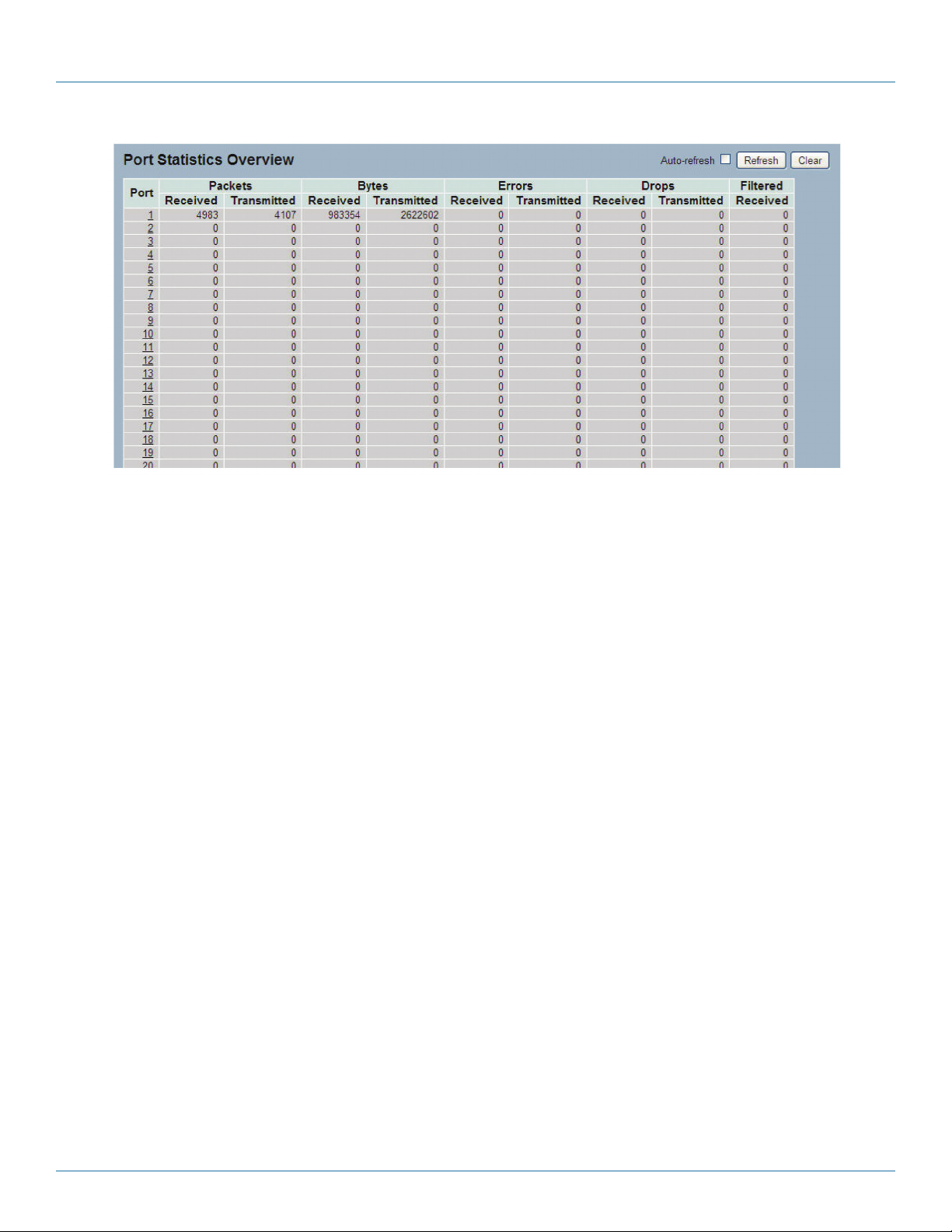
724-746-5500 | blackbox.com
Chapter 6: Configuration
Figure 6-3. The Port Statistics Overview screen.
Parameter Description
Port: The logical port for the settings contained in the same row.
Packets: The number of received and transmitted packets per port.
Bytes: The number of received and transmitted bytes per port.
Errors: The number of frames received in error and the number of incomplete transmissions per port.
Drops: The number of frames discarded because of ingress or egress congestion.
Filtered: The number of received frames filtered by the forwarding
Auto-refresh: Check the box next to auto-refresh to refresh the information automatically.
Upper right icon (Refresh, Clear): Click refresh the port statistics information manually. Or click “Clear” to clean up all port
statistics.
6.1.4 Detailed Statistics
The section describes how to provide detailed traffic statistics for a specific switch port. Use the port select box to select which
switch port details to display.
The displayed counters are the totals for receive and transmit, the size counters are for receive and transmit, and the error
counters are for receive and transmit.
Web Interface
To display the per port and port detailed statistics overview in the Web interface:
1. Click “Configuration,” “Port,” then “Detailed Port Statistics.”
2. Scroll through the Port Index to select the port for which you want to show the detailed port statistics overview.
3. If you want to auto-refresh the information then click on the “Auto-refresh” button.
4. Click “Refresh” to refresh the port detailed statistics or click “Clear” to clear al information.
724-746-5500 | blackbox.com
Page 44
LGB5028A User‘s Manual
Page 45

Chapter 6: Configuration
Figure 6-4. The Detailed Port Statistics Overview screen.
Parameter Description
Auto-refresh: Click on this box to refresh the port statistics information automatically.
Upper left scroll bar: Scroll which port to display the Port statistics with “Port-0”, “Port-1...”
Receive Total and Transmit Total
Rx and Tx Packets: The number of received and transmitted (good and bad) packets.
Rx and Tx Octets: The number of received and transmitted (good and bad) bytes. Includes FCS, but excludes framing bits.
Rx and Tx Unicast: The number of received and transmitted (good and bad) unicast packets.
Rx and Tx Multicast: The number of received and transmitted (good and bad) multicast packets.
Rx and Tx Broadcast: The number of received and transmitted (good and bad) broadcast packets.
Rx and Tx Pause: A count of the MAC control frames received or transmitted on this port that have an opcode indicating a
PAUSE operation.
Receive and Transmit Size Counters
The number of received and transmitted (good and bad) packets split into categories based on their respective frame sizes.
Receive and Transmit Queue Counters
The number of received and transmitted packets per input and output queue.
Receive Error Counters
Rx Drops: Show the number of frames dropped because the received buffers are missing or congested.
Rx CRC/Alignment: The number of frames received with CRC or alignment errors.
Rx Undersize: The number of short 1 frames received with valid CRC.
Rx Oversize: The number of long 2 frames received with valid CRC.
Rx Fragments: The number of short 1 frames received with invalid CRC.
LGB5028A User‘s Manual
724-746-5500 | blackbox.com
Page 45
Page 46

724-746-5500 | blackbox.com
Chapter 6: Configuration
Rx Jabber: The number of long 2 frames received with invalid CRC.
Rx Filtered: Show the number of received frames filtered by the forwarding process.
Short frames are frames that are smaller than 64 bytes.
Long frames are frames that are longer than the configured maximum frame length for this port.
Transmit Error Counters
Tx Drop s : The number of frames dropped because of output buffer congestion.
Tx Late/Exc. Coll.: The number of frames dropped because of excessive or late collisions.
Auto-refresh: Click on the auto-refresh button to refresh the Queuing Counters automatically.
Upper right icon (Refresh, clear): Click on Refresh to refresh the Port Detail Statistics or click on clear to clear the statistics
manually.
6.1.5 QoS Statistics
Display the QoS detailed queuing counters for a specific switch port, or for the different queues for all switch ports.
Web Interface
To display the queuing counters in the Web interface:
1. Click “Configuration,” “Port,” then “QoS Statistics.”
2. If you want to auto-refresh the information, click on the ”Auto-refresh” button.
3. Click “ Refresh“ to refresh the queueing counters or click “Clear” to clear all information.
Page 46
Figure 6-5. The Queuing Counters Overview screen.
724-746-5500 | blackbox.com
LGB5028A User‘s Manual
Page 47

Chapter 6: Configuration
Parameter Description
Port: The logical port for the settings contained in the same row.
Q(n): Qn is the Queue number, QoS queues per port. Q0 is the lowest priority queue.
Rx /Tx : The number of received and transmitted packets per queue.
Auto-refresh: Click on auto-refresh to refresh the queuing counters automatically.
Upper right icon (Refresh, clear): You can click on these buttons to refresh the queuing counters or clear them manually.
6.1.6 SFP Information
The section describes detailed information about the SFP module, including connector type, fiber type, wavelength, band rate,
and vendor OUI.
Web Interface
To display the SFP information in the Web interface: Click “Configuration,” “Port,” then “SFP Information.”
Figure 6-6. SFP Information screen.
Parameter Description
Connector Type: Display the connector type, for instance, UTP, SC, ST, LC, and so on.
Fiber Type: Display the fiber mode, for instance, multimode, single-mode.
Tx Central Wavelength: Display the fiber optical transmitting central wavelength, for instance, 850 nm, 1310 nm, 1550 nm, and
so on.
Baud Rate: Display the maximum baud rate of the fiber module supported, for instance, 10M, 100M, 1G, and so on.
Vendor OUI: Display the manufacturer's OUI code which is assigned by IEEE.
Vendor Name: Display the company name of the module manufacturer.
Vendor PN: Display the module manufacturer’s part number.
Vendor Rev (Revision): Display the module revision.
LGB5028A User‘s Manual
724-746-5500 | blackbox.com
Page 47
Page 48

724-746-5500 | blackbox.com
Chapter 6: Configuration
Vendor SN (Serial Number): Show the serial number assigned by the manufacturer.
Date Code: Show the date this SFP module was made.
Temperature: Show the current temperature of the SFP module.
Vcc: Show the working DC voltage of the SFP module.
Mon1 (Bias): Show the bias current of the SFP module.
Mon2 (TX PWR): Show the transmit power of the SFP module.
Mon3 (RX PWR): Show the receiver power of the SFP module.
6.2 ACL
The LGB5028A or LGB5052A switch access control list (ACL) is probably the most commonly used object in the IOS. It is used not
only for packet filtering, but also for selecting types of traffic to be analyzed, forwarded, or influenced in some way. The ACLs are
divided into EtherTypes, IPv4, ARP protocol, MAC, and VLAN parameters, etc. Here we will just go over the standard and
extended access lists for TCP/IP. As you create access control entries (ACEs) for ingress classification, you can assign a policy for
each port, (the policy number is 1–8), however, each policy can be applied to any port. This makes it very easy to determine what
type of ACL policy you will be working with.
6.2.1 Ports
The section describes how to configure the ACL parameters (ACE) of each switch port.
These parameters will affect frames received on a port unless the frame matches a specific ACE.
Web Interface
To configure the ACL Ports Configuration in the Web interface:
1. Click “Configuration,” “ACL,” then “Ports.”
2. Scroll to the specific parameter value to select the correct value for port ACL setting.
3. Click “Save.”
4. To cancel the setting, click the “Reset” button. It will revert to previously saved values.
5. When configuration is complete, you will see the port counter. Click “Refresh” to update the counter or “Clear” to clear the
information.
Page 48
724-746-5500 | blackbox.com
LGB5028A User‘s Manual
Page 49
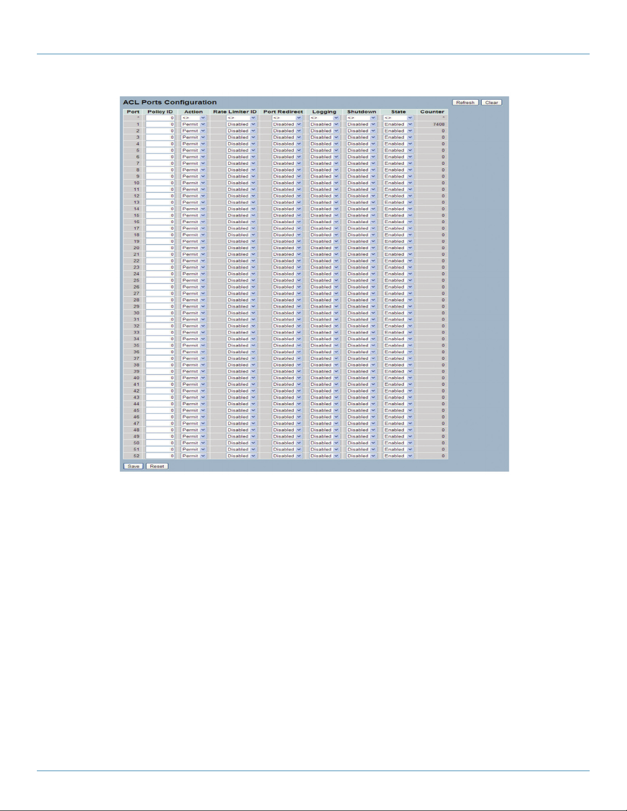
Chapter 6: Configuration
Figure 6-7. The ACL Ports Configuration screen.
Parameter Description
Port: The logical port for the settings contained in the same row.
Policy ID: Select the policy to apply to this port. The allowed values are 1 through 8. The default value is 1.
Action: Select whether forwarding is permitted (“Permit”) or denied (“Deny”). The default value is “Permit.”
Rate Limiter ID: Select which rate limiter to apply on this port. The allowed values are “Disabled” or the values 1 through 16.
The default value is “Disabled.”
Port Redirect: Enables you to select which port frames are redirected. The alllowed values are “Disabled” on a specific port
number. The default value is “Disabled.”
LGB5028A User‘s Manual
724-746-5500 | blackbox.com
Page 49
Page 50

724-746-5500 | blackbox.com
Chapter 6: Configuration
Logging: Specify the logging operation of this port. The allowed values are:
Enabled: Frames received on the port are stored in the System Log.
Disabled: Frames received on the port are not logged.
The default value is “Disabled.”
NOTE: The system log memory size and logging rate is limited.
Shutdown: Specify the shutdown operation of this port. The allowed values are:
Enabled: If a frame is received on the port, the port will be disabled.
Disabled: Port shut down is disabled.
The default value is “Disabled.”
State: Specifies the port state. The allowed values are:
Enabled: Open port by changing the volatile port configuration of the ACL user module.
Disable: Close port byc changing the volatile port configuration of the ACL user module.
The default is “Enabled.”
Counter: Count the number of frames that match this ACL.
Buttons:
Save: Click to save changes.
Reset: Click to undo any changes made locally and revert to previously saved values.
Upper right icon (Refresh, clear): Click on the “Refresh” icon to refresh the ACL Port Configuration or click on Clear to clear
them manually.
6.2.2 Rate Limiters
The section describes how to configure the switch’s ACL rate limiter parameters. Users can set the rate limiter value level in pps or
kbps units.
Web Interface
To configure ACL Rate Limiter in the web interface:
1. Click “Configuration,” “ACL,” then “Rate Limiter.”
2. Specify the rate field and the range from 0 to 3276700.
3. Scroll through the units in pps or kbps.
4. Click on the “Save” button to save the setting.
5. To cancel the setting, click on the “Reset” button. The settings will revert to previously saved values.
Page 50
724-746-5500 | blackbox.com
LGB5028A User‘s Manual
Page 51

Chapter 6: Configuration
Figure 6-8. The ACL Rate Limiter Configuration screen.
Parameter Description
Rate Limiter ID: The rate limiter ID for the settings contained in the same row.
Rate: The allowed values are: 0–3276700 in pps or 0, 100, 200, 300, ..., 1000000 in kbps.
Unit: Specify the rate unit. The allowed values are:
pps: packets per second.
kbps: Kilobits per second.
Buttons:
Save: Click to save changes.
Reset: Click to undo any changes made locally and revert to previously saved values.
6.2.3 Access Control List
The section describes how to configure Access Control List rule. An Access Control List (ACL) is a sequential list of permitted or
denied conditions that apply to IP addresses, MAC addresses, or other more specific criteria. This switch tests ingress packets
against the conditions in an ACL one by one. A packet will be accepted as soon as it matches a permit rule, or dropped as soon
as it matches a deny rule. If no rules match, the frame is accepted. Other actions can also be invoked when a matching packet is
found, including rate limiting, copying matching packets to another port or to the system log, or shutting down a port.
Figure 6-9 shows the ACL, which is made up of the Access Control Entries (ACEs) defined on this switch. Each row describes the
ACE that is defined. The maximum number of ACEs is 256 on each switch. Click on the lowest plus sign to add a new ACE to the
list. The reserved ACEs are used for internal protocol. They cannot be edited or deleted, and the order sequence cannot be
changed. The priority is highest.
LGB5028A User‘s Manual
724-746-5500 | blackbox.com
Page 51
Page 52

724-746-5500 | blackbox.com
Chapter 6: Configuration
Web Interface
To configure Access Control List in the Web interface:
1. Click “Configuration,” “ACE,” then “Configuration.”
2. Click the button to add a new ACE, or use the other ACE modification buttons to specify the editing action (that is, edit,
delete, or move the relative position of entry in the list).
3. Specify the parameter of the ACE.
4. Click on the “Save” button to save the setting.
5. If you want to cancel the setting, click on the “Reset” button. The setting will revert to previously saved values.
NOTE: When editing an entry on the ACL Configuration page, the Items displayed depend on various selections, such as Frame
Type and IP Protocol Type.
6. Specify the relevant criteria to match for this rule, and set the actions to take when a rule is matched (such as Rate Limiter, Port
Copy, Logging, and Shutdown).
Figure 6-9. The Access Control List Configuration screen.
Parameter Description
Ingress Port: Indicate the ingress port of the ACE. Possible values are:
Any: The ACE will match any ingress port.
Policy: The ACE will match ingress ports with a specific policy.
Port: The ACE will match a specific ingress port.
724-746-5500 | blackbox.com
Page 52
LGB5028A User‘s Manual
Page 53

Chapter 6: Configuration
Frame Type: Indicate the frame type of the ACE. Possible values are:
Any: The ACE will match any frame type.
Ethernet Type: The ACE will match Ethernet Type frames.
NOTE: An Ethernet-type-based ACE will not get matched by IP and ARP frames.
ARP: The ACE will match ARP/RARP frames.
IPv4: The ACE will match all IPv4 frames.
Action: Indicate the forwarding action of the ACE.
Permit: Frames matching the ACE may be forwarded and learned.
Deny: Frames matching the ACE are dropped.
Rate Limiter: Indicate the rate limiter number of the ACE. The allowed range is 1 to 16.
When “Disabled” is displayed, the rate limiter operation is disabled.
Port Copy: Indicate the port copy operation of the ACE. Frames matching the ACE are copied to the port number. The allowed
values are “Disabled” or a specific port number. When “Disabled” is displayed, the port copy operation is disabled.
Mirror:
Specify the mirror operation of this port. The allowed values are:
Enabled: Frames received on the port are mirrored.
Disabled: Frames received on the port are not mirrored.
The default value is “Disabled.”
Logging:
Indicate the logging operation of the ACE. Possible values are:
Enabled: Frames matching the ACE are stored in the System Log.
Disabled: Frames matching the ACE are not logged.
NOTE: The system log memory size and logging rate is limited.
Shutdown: Indicates the port shutdown operation of the ACE. Possible values are:
Enabled: If a frame matches the ACE, the ingress port will be disabled.
Disabled: Port shutdown is disabled for the ACE.
Counter: The counter indicates the number of times the ACE was hit by a frame.
Modification Buttons:
You can modify each ACE in the table using the following buttons:
“+” button: Inserts a new ACE before the current row.
“e” button: Edits the ACE row.
“up arrow” button: Moves the ACE up the list.
“down arrow” button: Moves the ACE down the list.
“X” button: Deletes the ACE.
“+’ button: The lowest plus sign adds a new entry at the bottom of the ACE listings.
LGB5028A User‘s Manual
724-746-5500 | blackbox.com
Page 53
Page 54

724-746-5500 | blackbox.com
Chapter 6: Configuration
MAC Parameters:
SMAC Filter: (Only display when the frame type is Ethernet Type or ARP.) Specify the source MAC filter for this ACE.
Any: No SMAC filter is specified. (SMAC filter status is “don't-care.”)
Specific: If you want to filter a specific source MAC address with this ACE, choose this value. A field for entering an SMAC value
appears.
SMAC Value: When “Specific” is selected for the SMAC filter, you can enter a specific source MAC address. The legal format is
"xx-xx-xx-xx-xx-xx" or "xx.xx.xx.xx.xx.xx" or "xxxxxxxxxxxx" (x is a hexadecimal digit). A frame that hits this ACE matches this
SMAC value.
DMAC Filter: Specify the destination MAC filter for this ACE.
Any: No DMAC filter is specified. (DMAC filter status is “don't-care”.)
MC: Frame must be multicast.
BC: Frame must be broadcast.
UC: Frame must be unicast.
Specific: If you want to filter a specific destination MAC address with this ACE, choose this value. A field for entering a DMAC
value appears.
DMAC Value: When "Specific" is selected for the DMAC filter, you can enter a specific destination MAC address. The legal
format is "xx-xx-xx-xx-xx-xx" or "xx.xx.xx.xx.xx.xx" or "xxxxxxxxxxxx" (x is a hexadecimal digit). A frame that hits this ACE
matches this DMAC value.
VLAN Parameters: Specify the VLAN parameters.
VLAN ID Filter: Select an option from the drop-down menu.
Tag Priority: Select an option from the drop-down menu.
Buttons:
Save: Click to save changes.
Reset: Click to undo any changes made locally and revert to previously saved values.
Auto-refresh: Check this box to refresh the information automatically.
Upper right icon (Refresh, Clear, Remove All): Click on this button to refresh the ACL configuration or manually clear the ACLs.
Choose “Remove All” all to remove all ACL configurations on the table.
6.2.4 ACL Status
The section shows the ACL status by different ACL users. Each row describes the ACE that is defined. A conflict occurs if a specific
ACE is not applied to the hardware because of hardware limitations. The maximum number of ACEs is 256 on each switch.
Web Interface
To display the ACL status in the Web interface:
1. Click “Configuration,” “ACL,” then “ACL status.”
2. To auto-refresh the information, click on the “Auto-refresh” button.
3. Click ““Refresh” to refresh the ACL Status.
724-746-5500 | blackbox.com
Page 54
LGB5028A User‘s Manual
Page 55

Figure 6-10. The ACL Status screen.
Parameter Description
User: Indicate the ACL user.
Ingress Port: Indicate the ingress port of the ACE. Possible values are:
Any: The ACE will match any ingress port.
Policy: The ACE will match ingress ports with a specific policy.
Port: The ACE will match a specific ingress port.
Chapter 6: Configuration
Frame Type: Indicate the frame type of the ACE. Possible values are:
Any: The ACE will match any frame type.
EType: The ACE will match Ethernet Type frames.
NOTE: An Ethernet-type-based ACE will not get matched by IP and ARP frames.
ARP: The ACE will match ARP/RARP frames.
IPv4: The ACE will match all IPv4 frames.
Action: Indicate the forwarding action of the ACE.
Permit: Frames matching the ACE may be forwarded and learned.
Deny: Frames matching the ACE are dropped.
Rate Limiter: Indicate the rate limiter number of the ACE. The allowed range is 1 to 16.
When “Disabled” is displayed, the rate limiter operation is disabled.
Port Copy: Indicate the port copy operation of the ACE. Frames matching the ACE are copied to the port number. The allowed
values are “Disabled” or a specific port number. When “Disabled” is displayed, the port copy operation is disabled.
Mirror: Specify the mirror operation of this port. The allowed values are:
Enabled: Frames received on the port are mirrored.
Disabled: Frames received on the port are not mirrored.
The default value is “Disabled.”
CPU: Forward the packet that matched the specific ACE to CPU.
CPU Once: Forward the first packet that matched the specific ACE to CPU.
Counter: The counter indicates the number of times the ACE encountered a frame.
LGB5028A User‘s Manual
724-746-5500 | blackbox.com
Page 55
Page 56

724-746-5500 | blackbox.com
Chapter 6: Configuration
Conflict: Indicate the hardware status of the specific ACE. The specific ACE is not applied to the hardware because of hardware
limitations.
Auto-refresh: Click on this button to refresh the information automatically.
Upper right icon (Refresh): Click to refresh the ACL status information manually.
6.3 Aggregation
The aggregation is used to configure the Link Aggregation settings. You can bundle more than one port with the same speed,
full-duplex, and the same MAC to be a single logical port, so the logical port aggregates the bandwidth of these ports. This
means you can apply your current Ethernet equipment’s bandwidth to build the bandwidth aggregation. For example, if there are
three Fast Ethernet ports aggregated in a logical port, then this logical port has bandwidth three times as high as a single Fast
Ethernet port has.
6.3.1 Static Trunk
Ports using Static Trunk as their trunk method can choose their unique Static GroupID to form a logical “trunked port.” The
benefit of using Static Trunk method is that a port can immediately become a member of a trunk group without any handshaking
with its peer port. This is also a disadvantage because the peer ports of your static trunk group may not know that they should
be aggregated together to form a “logical trunked port.” We strongly recommend that you use Static Trunk on both ends of a
link.
NOTE: Low-speed links will stay in “not ready” state when using static trunk to aggregate with high-speed links.
Web Interface
To configure the Trunk Aggregation Hash mode and Aggregation Group in the Web interface:
1. Click “Configuration,” “Static Trunk,” and then “Aggregation Mode Configuration.”
2. Enable or disable the aggregation mode function.
Enable the Aggregation Group ID and Port members.
3. Click on the “Save” button to save the setting.
4. To cancel the setting, click the “Reset” button. It will revert to previously saved values.
Page 56
724-746-5500 | blackbox.com
LGB5028A User‘s Manual
Page 57

Chapter 6: Configuration
Figure 6-11. The Aggregation Mode Configuration screen.
Parameter Description
Hash Code Contributors
Source MAC Address: The Source MAC address can be used to calculate the destination port for the frame. Check to enable the
use of the Source MAC address, or uncheck to disable. By default, Source MAC Address is enabled.
Destination MAC Address: The Destination MAC Address can be used to calculate the destination port for the frame. Check to
enable the use of the Destination MAC Address, or uncheck to disable. By default, Destination MAC Address is disabled.
IP Address: The IP address can be used to calculate the destination port for the frame. Check to enable the use of the IP Address,
or uncheck to disable. By default, IP Address is enabled.
TCP/UDP Port Number: The TCP/UDP port number can be used to calculate the destination port for the frame. Check to enable
the use of the TCP/UDP Port Number, or uncheck to disable. By default, TCP/UDP Port Number is enabled.
Aggregation Group Configuration
Locality: Indicates the aggregation group type. This field is only valid for switches.
Global: The group members may reside on different units. The device supports two 8-port global aggregations.
Local: The group members reside on the same unit. Each local aggregation may consist of up to 16 members.
Group ID: Indicates the group ID for the settings contained in the same row. Group ID “Normal” indicates there is no aggregation. Only one group ID is valid per port.
LGB5028A User‘s Manual
724-746-5500 | blackbox.com
Page 57
Page 58

724-746-5500 | blackbox.com
Chapter 6: Configuration
Port Members: Each switch port is listed for each group ID. Select a radio button to include a port in an aggregation, or clear
the radio button to remove the port from the aggregation. By default, no ports belong to any aggregation group. Only fullduplex ports can join an aggregation and ports must be in the same speed in each group.
Buttons:
Save: Click to save changes.
Reset: Click to undo any changes made locally and revert to previously saved values.
6.3.2 LACP
Ports using Link Aggregation Control Protocol (according to IEEE 802.3ad specification) as their trunking method can choose their
unique LACP GroupID to form a logical “trunked port.” The benefit of using LACP is that a port makes an agreement with its
peer port before it becomes a ready member of a “trunk group” (also called aggregator). LACP is safer than the static trunk
trunking method.
Configuration
This page allows the user to inspect the current LACP port configurations, and possibly change them as well. An LACP trunk
group with more than one ready member-ports is a “real trunked” group. An LACP trunk group with only one or less than one
ready member-ports is not a “real trunked” group.
Web Interface
To configure the Trunk Aggregation LACP parameters in the Web interface:
1. Click “Configuration,” “LACP,” “Configuration.”
2. Enable or disable the LACP on the port of the switch. Scroll thorugh the the key parameters with “Auto” or “Specific.” Default
is “Aut o.”
3. Scroll the Role with “Active” or “Passive.” Default is “Active.”
4. Click “Save” to save the setting.
5. To cancel the setting, click the “Reset” button. It will revert to previously saved values.
Page 58
724-746-5500 | blackbox.com
LGB5028A User‘s Manual
Page 59

Chapter 6: Configuration
Figure 6-12. The LACP Port Configuration screen.
Parameter Description
Port: The switch port number.
LACP Enabled: Click to enable LACP on this switch port. LACP will form an aggregation when two or more ports are connected
to the same partner. LACP can form a maximum of 12 LLAGs per switch and 2 GLAGs.
Key: The Key value incurred by the port, range 1–65535 . The Auto setting will set the key as appropriate by the physical link
speed, 10Mb = 1, 100Mb = 2, 1Gb = 3. Using the Specific setting, a user-defined value can be entered. Ports with the same key
value can participate in the same aggregation group; ports with different keys cannot.
Role: Role shows the LACP activity status. “Active” will transmit LACP packets each second; “Passive” will wait for a LACP packet
from a partner (in other words, it will “speak if spoken to”).
Buttons:
Save: Click to save changes.
LGB5028A User‘s Manual
724-746-5500 | blackbox.com
Page 59
Page 60

724-746-5500 | blackbox.com
Chapter 6: Configuration
Reset: Click to undo any changes made locally and revert to previously saved values.
System Status
When you set the LACP function on the switch, system status provides a status overview for all LACP instances.
Web Interface
To display the LACP System status in the Web interface:
1. Click “Configuration,” “LACP,” “System Status.”
2. If you want to auto-refresh the information, click on the “Auto-refresh” button.
3. Click “Refresh” to refresh the LACP System Status.
Figure 6-13. The LACP System Status screen.
Parameter Description
Aggr ID: The Aggregation ID associated with this aggregation instance. For LLAG the ID is shown as “isid:aggr-id” and for
GLAGs as “aggr-id.”
Partner System ID: The system ID (MAC address) of the aggregation partner.
Partner Key: The key that the partner has assigned to this aggregation ID.
Last Changed: The time since this aggregation changed.
Local Ports: Shows which ports are part of this aggregation for this switch. The format is: “Switch ID:Port.”
Auto-refresh: Click on this button to refresh the information automatically.
Upper right icon (Refresh): You can click to refresh the LACP System status information manually.
Port Status
When you complete setting the LACP function on the switch, it provides a Port Status overview for all LACP instances.
Web Interface
To display the LACP Port status in the Web interface:
1. Click “Configuration,” “LACP,” “Port Status.”
2. To auto-refresh the information, click on the “Auto-refresh” button.
3. Click “Refresh“ to refresh the LACP Port Status.
724-746-5500 | blackbox.com
Page 60
LGB5028A User‘s Manual
Page 61

Chapter 6: Configuration
Figure 6-14. The LACP Status screen.
Parameter Description
Port: The switch port number.
LACP: “Yes” means that LACP is enabled and the port link is up. “No” means that LACP is not enabled or that the port link is
down. “Backup” means that the port could not join the aggregation group but will join if another port leaves. Meanwhile, its
LACP status is disabled.
Key: The key assigned to this port. Only ports with the same key can aggregate together.
Aggr ID: The Aggregation ID assigned to this aggregation group. IDs 1 and 2 are GLAGs while IDs 3–14 are LLAGs.
LGB5028A User‘s Manual
724-746-5500 | blackbox.com
Page 61
Page 62
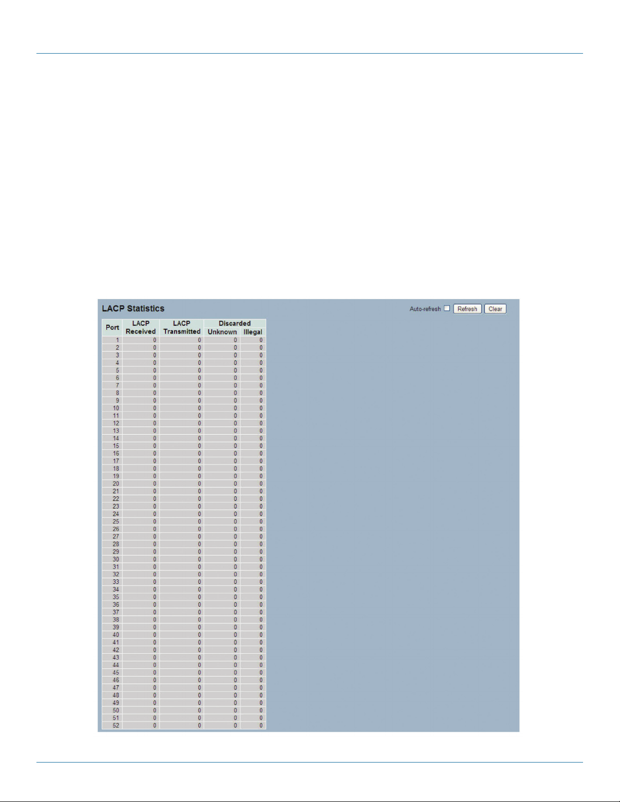
724-746-5500 | blackbox.com
Chapter 6: Configuration
Partner System ID: The partner's system ID (MAC address).
Partner Port: The partner's port number connected to this port.
Auto-refresh: Check this box to auto-refresh to refresh the information automatically.
Upper right icon (Refresh): Click this button to refresh the LACP port status information manually.
Port Statistics
After you set the LACP function on the switch, it provides a Port Statistics overview for all LACP instances.
Web Interface
To display the LACP Port statistics in the Web interface:
1. Click “Configuration,” “LACP,” “Port Statistics.”
2. To auto-refresh the information, check the “Auto-refresh” button.
3. Click “Refresh” to refresh the LACP Statistics.
Page 62
Figure 6-15. The LACP Statistics screen.
724-746-5500 | blackbox.com
LGB5028A User‘s Manual
Page 63

Chapter 6: Configuration
Parameter Description
Port: The switch port number.
LACP Received: Shows how many LACP frames have been received at each port.
LACP Transmitted: Shows how many LACP frames have been sent from each port.
Discarded: Shows how many unknown or illegal LACP frames have been discarded at each port.
Auto-refresh: Check this box to auto-refresh to refresh the information automatically.
Upper right icon (Refresh, Clear): Click on the “Refresh” button to refresh the LACP port statistics information manually or click on
the “Clear” button to clear all entries.
6.4 Spanning Tree
The Spanning Tree Protocol (STP) can be used to detect and disable network loops, and to provide backup links between
switches, bridges, or routers. This allows the switch to interact with other bridging devices (that is, an STP-compliant switch,
bridge, or router) in your network to ensure that only one route exists between any two stations on the network, and provide
backup links that automatically take over when a primary link goes down.
STP uses a distributed algorithm to select a bridging device (STP-compliant switch, bridge, or router) that serves as the root of the
spanning tree network. It selects a root port on each bridging device (except for the root device) which incurs the lowest path
cost when forwarding a packet from that device to the root device. Then it selects a designated bridging device from each LAN
that incurs the lowest path cost when forwarding a packet from that LAN to the root device. All ports connected to designated
bridging devices are assigned as designated ports. After determining the lowest cost spanning tree, it enables all root ports and
designated ports, and disables all other ports. Network packets are therefore only forwarded between root ports and designated
ports, eliminating any possible network loops.
Figure 6-16. Spanning tree.
Once a stable network topology has been established, all bridges listen for “Hello BPDUs” (Bridge Protocol Data Units)
transmitted from the root bridge. If a bridge does not get a Hello BPDU after a predefined interval (Maximum Age), the bridge
assumes that the link to the root bridge is down. This bridge will then initiate negotiations with other bridges to reconfigure the
network to reestablish a valid network topology.
6.4.1 Bridge Settings
The section describes how to configure the spanning tree bridge and STP system settings. It allows you to configure STP
system settings that are used by all STP bridge instances in the switch.
Web Interface
To configure the Spanning Tree Bridge Settings parameters in the Web interface:
1. Click “Configuration,” “Spanning Tree,” “Bridge Settings”
2. Scroll to select the parameters and write down available value of parameters in blank field in Basic Settings.
3. Enable or disable the parameters and write down available value of parameters in the blank field in Advanced settings.
LGB5028A User‘s Manual
724-746-5500 | blackbox.com
Page 63
Page 64

724-746-5500 | blackbox.com
Chapter 6: Configuration
4. Click the “Save” button to save the setting.
5 .If you want to cancel the setting, click the “Reset” button. It will revert to previously saved values.
Figure 6-17. The STP Bridge Configuration screen.
Parameter Description
Basic Settings
Protocol Version: Show the STP protocol version setting. Valid values are STP, RSTP, and MSTP.
Bridge Priority: Control the bridge priority. Lower numeric values have better priority. The bridge priority plus the MSTI instance
number, concatenated with the 6-byte MAC address of the switch, forms a Bridge Identifier. For MSTP operation, this is the
priority of the CIST. Otherwise, this is the priority of the STP/RSTP bridge.
Forward Delay: The delay used by STP bridges to transmit root and designated ports to forwarding (used in STP compatible
mode). Valid values are in the range 4 to 30 seconds.
Max Age: Show the maximum age of the information transmitted by the bridge when it is the root bridge. Valid values are in the
range of 6 to 40 seconds, and MaxAge must be <= (FwdDelay-1)*2.
Maximum Hop Count: This defines the initial value of remaining hops for MSTI information generated at the boundary of an
MSTI region. It defines how many bridges a root bridge can distribute its BPDU information to. Valid values are in the range of 6
to 40 hops.
Transmit Hold Count: The number of BPDUs a bridge port can send per second. When exceeded, transmission of the next
BPDU will be delayed. Valid values are in the range of 1 to 10 BPDUs per second.
Advanced Settings
Edge Port BPDU Filtering: Control whether a port explicitly configured as edge will transmit and receive BPDUs.
Edge Port BPDU Guard: Control whether a port explicitly configured as edge will disable itself when it receives a BPDU. The
port will enter the error-disabled state, and will be removed from the active topology.
Page 64
724-746-5500 | blackbox.com
LGB5028A User‘s Manual
Page 65

Chapter 6: Configuration
Port Error Recovery: Control whether a port in the error-disabled state automatically will be enabled after a certain time. If
recovery is not enabled, ports have to be disabled and re-enabled for normal STP operation. The condition is also cleared by a
system reboot.
Port Error Recovery Timeout: The time to pass before a port in the error-disabled state can be enabled. Valid values are
between 30 and 86400 seconds (24 hours).
Buttons:
Save: Click to save changes.
Reset: Click to undo any changes made locally and revert to previously saved values.
6.4.2 MSTI Mapping
MSTI mapping is used when you implement a Spanning Tree protocol on the switch. The CIST is not available for explicit
mapping; it will receive the VLANs not explicitly mapped. Set the list of VLANs mapped to the MSTI. The VLANs must be
separated with a comma and/or space. A VLAN can only be mapped to one MSTI. An unused MSTI should just be left empty
(that is, not have any VLANs mapped to it).
This section describes how to inspect and/or change the current STP MSTI bridge priority configurations.
Web Interface
To configure the Spanning Tree MSTI Mapping parameters in the Web interface:
1. Click “Configuration,” “Spanning Tree,” “MSTI Mapping.”
2. Specify the configuration identification parameters in the field. Specify the VLANs mapped blank field.
3. Click “Save” to save the setting.
4. To cancel the setting, click the “Reset” button. It will revert to previously saved values.
LGB5028A User‘s Manual
Figure 6-18. The MSTI Configuration screen.
724-746-5500 | blackbox.com
Page 65
Page 66

724-746-5500 | blackbox.com
Chapter 6: Configuration
Parameter Description
Configuration Identification
Configuration Name: The name identifying the VLAN to MSTI mapping. Bridges must share the name and revision, as well as
the VLAN-to-MSTI mapping configuration to share spanning trees for MSTIs (Intra-region). The name must be less than 32
characters long.
Configuration Revision: The revision of the MSTI configuration named above. This must be an integer between 0 and 65535.
MSTI Mapping
MSTI: Show the bridge instance. The CIST is not available for explicit mapping, so it will receive the VLANs not explicitly mapped.
VLANs Mapped: The list of VLANs mapped to the MSTI. The VLANs must be separated with a comma and/or space. A VLAN
can only be mapped to one MSTI. An unused MSTI should just be left empty. (that is, not have any VLANs).
Buttons
Save: Click to save changes.
Reset: Click to undo any changes made locally and revert to previously saved values.
6.4.3 MSTI Priorities
When you implement a Spanning Tree protocol on the switch, the CIST is the default instance that is always active. It controls the
bridge priority. Lower numeric values have better priority. The bridge priority plus the MSTI instance number, concatenated with
the 6-byte MAC address of the switch, forms a Bridge Identifier.
The section describes how to inspect and/or change the current STP MSTI bridge instance priority configurations.
Web Interface
To configure the Spanning Tree MSTI Priorities parameters in the Web interface:
1. Click “Configuration,” “Spanning Tree,” “MSTI Priorities.”
2. Use the drop-down menu to select the priority (maximum is 240). Priority default is 128.
3. Click “Save” to save the setting
4. To cancel the setting, click the “Reset” button. It will revert to previously saved values.
Page 66
724-746-5500 | blackbox.com
LGB5028A User‘s Manual
Page 67

Chapter 6: Configuration
Figure 6-19. The MSTI Configuration screen.
Parameter description:
MSTI:
Show the bridge instance. The CIST is the default instance (always active).
Priority: Control the bridge priority. Lower numeric values have better priority. The bridge priority plus the MSTI instance number,
concatenated with the 6-byte MAC address of the switch, forms a Bridge Identifier.
Buttons
Save: Click to save changes.
Reset: Click to undo any changes made locally and revert to previously saved values.
6.4.4 CIST Ports
When you implement a Spanning Tree protocol on the switch, you need to configure the CIST ports. The section explains how to
inspect and/or change the current STP CIST port configurations.
Web Interface
To configure the Spanning Tree CIST Ports parameters in the Web interface:
1. Click “Configuration,” “Spanning Tree,” “CIST Ports.”
2. Scroll through the list to set all parameters of CIST Aggregated Port Configuration.
3. Enable or disable the STP, then scoll and set all parameters of the CIST normal Port configuration.
4. Click “Save” to save the setting.
5. To cancel the setting, click the “Reset” button. It will revert to previously saved values.
LGB5028A User‘s Manual
724-746-5500 | blackbox.com
Page 67
Page 68

724-746-5500 | blackbox.com
Chapter 6: Configuration
Page 68
Figure 6-20. The STP CIST Port Configuration screen.
724-746-5500 | blackbox.com
LGB5028A User‘s Manual
Page 69

Chapter 6: Configuration
Parameter Description
Port: The switch port number of the logical STP port.
STP Enabled: Control whether STP is enabled on this switch port.
Path Cost: Controls the path cost incurred by the port. The Auto setting will set the path cost as appropriate by the physical link
speed, using the 802.1D recommended values. Using the Specific setting, you can enter a user-defined value. The path cost is
used when establishing the active topology of the network. Lower path cost ports are chosen as forwarding ports in favor of
higher path cost ports. Valid values are in the range 1 to 200000000.
Priority: Control the port priority. This can be used to control priority of ports having identical path cost. (See above).
operEdge (state flag): Show the Operational flag describing whether the port is connecting directly to edge devices. (No
Bridges attached). Transition to the forwarding state is faster for edge ports (having operEdge true) than for other ports.The value
of this flag is based on AdminEdge and AutoEdge fields. This flag is displayed as Edge in Monitor->Spanning Tree -> STP Detailed
Bridge Status.
AdminEdge: Control whether the operEdge flag should start as set or cleared. (The initial operEdge state when a port is
initialized.)
AutoEdge: Control whether the bridge should enable automatic edge detection on the bridge port. This allows operEdge to be
derived from whether BPDUs are received on the port or not.
Restricted Role: If enabled, causes the port not to be selected as Root Port for the CIST or any MSTI, even if it has the best
Spanning Tree priority vector. Such a port will be selected as an Alternate Port after the Root Port has been selected. If set, it can
cause lack of Spanning Tree connectivity. It can be set by a network administrator to prevent bridges external to a core region of
the network from influencing the Spanning Tree active topology, possibly because those bridges are not under the full control of
the administrator. This feature is also known as Root Guard.
Restricted TCN: If enabled, causes the port not to propagate received topology change notifications and topology changes to
other ports. If set, it can cause temporary loss of connectivity after changes in a Spanning Tree's active topology as a result of
persistently incorrect learned station location information. It is set by a network administrator to prevent bridges external to a core
region of the network, causing address flushing in that region, possibly because those bridges are not under the full control of the
administrator or the physical link state of the attached LANs transits frequently.
BPDU Guard:
If enabled, causes the port to disable itself upon receiving valid BPDUs. Contrary to the similar bridge setting, the port edge status
does not affect this setting. A port entering error-disabled state due to this setting is also subject to the bridge Port Error Recovery
setting.
Point to Point: Control whether the port connects to a point-to-point LAN rather than to a shared medium. This can be
automatically determined, or forced either true or false. Transition to the forwarding state is faster for point-to-point LANs than
for shared media.
Buttons
Save: Click to save changes.
Reset: Click to undo any changes made locally and revert to previously saved values.
6.4.5 MSTI Ports
The section describes how to inspect and/or change the current STP MSTI port configurations.
An MSTI port is a virtual port that is initialized separately for each active CIST (physical) port for each MSTI instance configured
on and applicable to the port. The MSTI instance must be selected before displaying actual MSTI port configuration options. It
contains MSTI port settings for physical and aggregated ports.
LGB5028A User‘s Manual
724-746-5500 | blackbox.com
Page 69
Page 70

724-746-5500 | blackbox.com
Chapter 6: Configuration
Web Interface
To configure the Spanning Tree MSTI Port Configuration parameters in the Web interface:
1. Click “Configuration,” “Spanning Tree,” “MSTI Ports.”
2. Scroll to select the MST1 or other MSTI Port.
3. Click “Get” to set the detail parameters of the MSTI Ports.
4. Scroll to set all parameters of the MSTI Port configuration.
5. Click “Save” to save the setting.
6. To cancel the setting, click the “Reset” button. It will revert to previously saved values.
Page 70
Figure 6-21. The MSTI Port Configuration screen.
724-746-5500 | blackbox.com
LGB5028A User‘s Manual
Page 71

Chapter 6: Configuration
Parameter Description
Port: The switch port number of the corresponding STP CIST (and MSTI) port.
Path Cost: Control the path cost incurred by the port. The Auto setting will set the path cost as appropriate by the physical link
speed, using the 802.1D recommended values. Using the “Specific” setting, a user-defined value can be entered. The path cost is
used when establishing the active topology of the network. Lower path cost ports are chosen as forwarding ports in favor of
higher path cost ports. Valid values are in the range 1 to 200000000.
Priority:
Control the port priority. This can be used to control priority of ports having identical port cost. (See above).
Buttons
Save: Click to save changes.
Reset: Click to undo any changes made locally and revert to previously saved values.
6.4.6 Bridge Status
After completing the MSTI Port configuration, you could request that the switch display the Bridge Status. The section provides
a status overview of all STP bridge instances. The displayed table contains a row for each STP bridge instance, and the column
displays the following information:
Web Interface
To display the STP Bridges’ status in the Web interface:
1. Click “Configuration,” “Spanning Tree,” “STP Bridges.”
2. To auto-refresh the information, check the the “Auto-refresh” box.
3. Click “ Refresh“ to refresh the STP Bridges.
Figure 6-22. The STP Bridges’ Status screen.
Parameter Description
MSTI: Show the Bridge Instance. This is also a link to the STP Detailed Bridge Status.
Bridge ID: The Bridge ID of this Bridge instance.
Root ID: The Bridge ID of the currently elected root bridge.
Root Port: The switch port currently assigned the root port role.
Root Cost: Root Path Cost. For the root bridge it is zero. For all other bridges, it is the sum of the Port Path Costs on the least
cost path to the root bridge.
Topology Flag: The current state of the Topology Change Flag of this Bridge instance.
Topology Change Last: The time since last Topology Change occurred.
LGB5028A User‘s Manual
724-746-5500 | blackbox.com
Page 71
Page 72

724-746-5500 | blackbox.com
Chapter 6: Configuration
Buttons
Auto-refresh: Check this box to refresh the information automatically.
Upper right icon (Refresh): Click on this button to refresh the STP Bridges status information manually.
6.4.7 Port Status
After you complete the STP configuration, you could request that the switch display the STP Port Status. The section explains how
to display the STP CIST port status for physical ports of the currently selected switch.
Web Interface
To display the STP Port status in the Web interface:
1. Click “Configuration,” “Spanning Tree,” “STP Port Status.”
2. To auto-refresh the information, check the “Auto-refresh” button.
3. Click “Refresh” to refresh the STP Bridges.
Page 72
Figure 6-23. The STP Port Status screen.
724-746-5500 | blackbox.com
LGB5028A User‘s Manual
Page 73

Chapter 6: Configuration
Parameter Description
Port: The switch port number of the logical STP port.
CIST Role: Show the current STP port role of the CIST port. The port role can be one of the following values: AlternatePort,
Backup Port, RootPort, DesignatedPort Disabled.
CIST State: Show the current STP port state of the CIST port. The port state can be one of the following values: Blocking
Learning Forwarding.
Uptime: The time since the bridge port was last initialized.
Auto-refresh: Check this box to refresh the information automatically.
Upper right icon (Refresh): Click on this button to refresh the STP Port status information manually.
6.4.8 Port Statistics
After you complete the STP configuration, you could make the switch display the STP Statistics. The section explains how to
request that the switch display the STP Statistics detail counters of bridge ports in the currently selected switch.
Web Interface
To display the STP Port status in the Web interface:
1. Click “Configuration,” “Spanning Tree,” “Port Statistics.”
2. If you want to auto-refresh the information, check the “Auto-refresh” button.
3. Click “Refresh” to refresh the STP bridges.
Figure 6-24. The STP Statistics screen.
Parameter Description
Port: The switch port number of the logical STP port.
MSTP: The number of MSTP Configuration BPDUs transmitted/received on the port.
RSTP: The number of RSTP Configuration BPDUs transmitted/received on the port.
STP: The number of legacy STP Configuration BPDUs transmitted/received on the port.
TCN: The number of legacy Topology Change Notification BPDUs transmitted/received on the port.
Discarded Unknown: The number of unknown Spanning Tree BPDUs received (and discarded) on the port.
Discarded Illegal: The number of illegal Spanning Tree BPDUs received (and discarded) on the port.
Auto-refresh: Check this box to refresh the information automatically.
Upper right icon (Refresh, Clear): You can click one of these buttons to refresh or clear the STP Statistics information
manually.
LGB5028A User‘s Manual
724-746-5500 | blackbox.com
Page 73
Page 74

724-746-5500 | blackbox.com
Chapter 6: Configuration
6.5 IGMP Snooping
The function is used to enable the multicast groups to forward the multicast packet to the member ports, saving bandwidth while
IP multicast packets are running over the network. This is because a switch that does not support IGMP or IGMP snooping can
not distinguish the multicast packet from the broadcast packet, so it can only treat every packet as a broadcast packet. Without
IGMP snooping, the multicast packet forwarding functions in the same way as the broadcast packet.
A switch that supports IGMP snooping with query, report, and leave, a type of packet exchanged between IP multicast router/
switch and IP multicast host, can update the information of the multicast table when a member (port) joins or leaves an IP
multicast destination Address. With this function, once a switch receives an IP multicast packet, it will forward the packet to the
members who joined in a specified IP multicast group before.
The packets will be discarded by the IGMP snooping if the user transmits multicast packets to the multicast group that was not
established in advance. IGMP mode enables the switch to use IGMP proxy or snooping on the switch, connecting to a router
closer to the root of the tree. This interface is the upstream interface. The router on the upstream interface should be running
I GM P.
6.5.1 Basic Configuration
The section describes how to set the basic IGMP snooping on the switch, which connects to a router closer to the root of the
tree. This interface is the upstream interface. The router on the upstream interface should be running IGMP.
Web Interface
To configure the IGMP Snooping parameters in the Web interface:
1. Click “Configuration,” “IGMP Snooping,” “Basic Configuration.”
2. Enable or disable Global configuration.
3. Select which port will become a Router Port or enable/disable the Fast Leave function..
4. Scroll to set the Throttling parameter.
5. Click “Save” to save the setting.
6. To cancel the setting, click the “Reset” button. It will revert to previously saved values.
Page 74
724-746-5500 | blackbox.com
LGB5028A User‘s Manual
Page 75

Chapter 6: Configuration
Figure 6-25. The IGMP Snooping Configuration screen.
Figure 6-26. The ICMP Snooping Configuration screen closeup.
Parameter description:
Snooping Enabled: Enable Global IGMP Snooping.
Unregistered IPMCv4 Flooding Enabled: Enable unregistered IPMCv4 traffic flooding.
IGMP SSM Range: SSM (Source-Specific Multicast) Range allows the SSM-aware hosts and routers to run the SSM service model
for the groups in the address range. Format: (IP address/sub mask).
LGB5028A User‘s Manual
724-746-5500 | blackbox.com
Page 75
Page 76

724-746-5500 | blackbox.com
Chapter 6: Configuration
Proxy Enabled: Enable IGMP Proxy. This feature can be used to avoid forwarding unnecessary join and leave messages to the
router side.
Port: Shows the physical port index of the switch.
Router Port:
Specify which ports act as router ports. A router port is a port on the Ethernet switch that leads towards the Layer 3 multicast
device or IGMP querier.
If an aggregation member port is selected as a router port, the whole aggregation will act as a router port.
Fast Leave: Enable the fast leave on the port.
Throttling: LImit the number of multicast groups to which a switch port can belong.
Buttons
Save: Click to save changes.
Reset: Click to undo any changes made locally and revert to previously saved values.
6.5.2 VLAN Configuration
The section describes the VLAN configuration setting process integrated with IGMP Snooping function. Each setting page shows
up to 99 entries from the VLAN table. The default is 20, selected through the “entries per page” input field. When first visited,
the Web page will show the first 20 entries from the beginning of the VLAN table. The first displayed will be the one with the
lowest VLAN ID found in the VLAN table. The “VLAN” input fields enable the user to select the starting point in the VLAN table.
Clicking the button will update the displayed table starting from that or the next closest VLAN table match.
Web Interface
To configure the IGMP Snooping VLAN Configuration in the Web interface:
1. Click “Configuration,” “IGMP Snooping,” “VLAN Configuration.”
2. Enable or disable Snooping, IGMP Querier. Specify the parameters in the blank field.
3. Click on the “Refresh” button to update the data or click “<<” or “>>” to display the previous/next entry.
4. Click “Save” to save the setting.
5. To cancel the setting, click the “Reset” button. It will revert to previously saved values
Figure 6-27. The IGMP Snooping VLAN Configuration.
Parameter Description
VLAN ID: Displays the VLAN ID of the entry.
Snooping Enabled: Enable the per-VLAN IGMP Snooping. Up to 32 VLANs can be selected.
724-746-5500 | blackbox.com
Page 76
LGB5028A User‘s Manual
Page 77

Chapter 6: Configuration
IGMP Querier: A router sends IGMP query messages onto a particular link. This router is called the querier. Enable the IGMP
querier in the VLAN.
Compatibility: Compatibility is maintained by hosts and routers taking appropriate actions depending on the versions of IGMP
operating on hosts and routers within a network. The allowed selection is IGMP-Auto, Forced IGMPv1, Forced IGMPv2, Forced
IGMPv3; default compatibility value is IGMP-Auto.
Rv: Show Robustness Variable. The Robustness Variable allows tuning for the expected packet loss on a network. The allowed
range is 1 to 255; default robustness variable value is 2.
QI: Query Interval. The Query Interval is the interval between General Queries sent by the Querier. The allowed range is 1 to
31744 seconds; default query interval is 125 seconds.
QRI: Query Response Interval. The Max. Response Time used to calculate the Max. Resp Code inserted into the periodic General
Queries. The allowed range is 0 to 31744 in tenths of seconds; default query response interval is 100 in tenths of seconds
(10 seconds).
LLQI (LMQI for IGMP):
Show the Last Member Query Interval. The Last Member Query Time is the time value represented by the Last Member Query
Interval, multiplied by the Last Member Query Count. The allowed range is 0 to 31744 in tenths of seconds; default last member
query interval is 10 in tenths of seconds (1 second).
URI: Show the Unsolicited Report Interval. The Unsolicited Report Interval is the time between repetitions of a host's initial report
of membership in a group. The allowed range is 0 to 31744 seconds; default unsolicited report interval is 1 second.
Buttons:
Save: Click to save changes.
Reset: Click to undo any changes made locally and revert to previously saved values.
Upper right icon (Refresh, |<<, >>): Click to refresh the displayed table starting from the “VLAN” input fields. Or click “|<<” to
update the table starting from the first entry in the VLAN table, that is, the entry with the lowest VLAN ID. Click “>> “ to update
the table, starting with the entry after the last entry currently displayed.
6.5.3 Port Group Filtering
The section describes how to set the IGMP port group filtering. In some applications, such as metropolitan or multiple-dwelling
unit (MDU) installations, a user might want to control the multicast groups that a user on a switch port can belong to. The IGMP
filtering feature enables the user to control the distribution of multicast services, such as IP/TV, based on a subscription or service
plan.
With this feature, you can filter multicast joins on a per-port basis by configuring IP multicast profiles and associating them with
individual switch ports. An IGMP profile can contain one or more multicast groups and specifies whether access to the group is
permitted or denied. If an IGMP profile denying access to a multicast group is applied to a switch port, the IGMP join report
requesting the stream of IP multicast traffic is dropped, and the port is not allowed to receive IP multicast traffic from that group.
If the filtering action permits access to the multicast group, the IGMP report from the port is forwarded for normal processing.
IGMP filtering controls only IGMP membership join reports and has no relationship to the function that directs the forwarding of
IP multicast traffic.
Web Interface
To configure the IGMP Snooping Port Group Configuration in the Web interface:
1. Click “Configuration,” “IGMP Snooping,” “Port Group Filtering.”
2. Click “Add new Filtering Group.”
3. Scroll the Port to enable the Port Group Filtering. Specify the Filtering Groups in the blank field.
LGB5028A User‘s Manual
724-746-5500 | blackbox.com
Page 77
Page 78
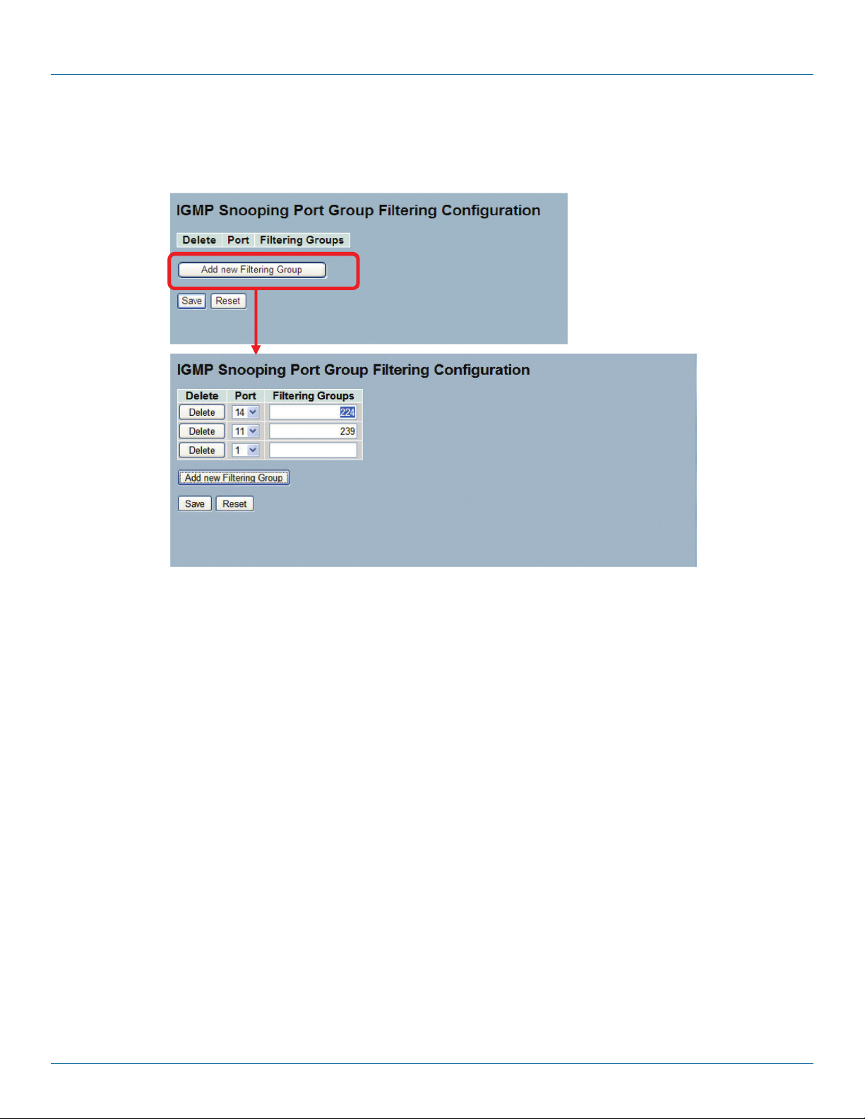
724-746-5500 | blackbox.com
Chapter 6: Configuration
4. Click “Save” to save the setting.
5. To cancel the setting, click the “Reset” button. It will revert to previously saved values.
Figure 6-28. The IGMP Snooping Port Group Filtering Configuration screen.
Parameter Description
Delete: Click to delete the entry. It will be deleted during the next save.
Port: To select the port, enable the IGMP Snooping Port Group Filtering function.
Filtering Groups: The IP Multicast Group that will be filtered.
Buttons:
Save: Click to save changes.
Reset: Click to undo any changes made locally and revert to previously saved values.
6.5.4 Status
After you complete the IGMP snooping configuration, set the switch to display the IGMP snooping status. This section explains
how to do this.
Web Interface
To display the IGMP Snooping status in the Web interface:
1. Click “Configuration,” “IGMP Snooping,” “Status.”
2. To auto-refresh the information, check the box next to “Auto-refresh.”
3. Click “Refresh” to refresh the IGMP Snooping Status.
4. Click “Clear” to clear the IGMP Snooping Status.
724-746-5500 | blackbox.com
Page 78
LGB5028A User‘s Manual
Page 79

Chapter 6: Configuration
Figure 6-29. The IGMP Snooping Status screen.
Parameter Description
VLAN ID: The VLAN ID of the entry.
Querier Version: Working Querier Version currently.
Host Version: Working Host Version currently.
LGB5028A User‘s Manual
724-746-5500 | blackbox.com
Page 79
Page 80

724-746-5500 | blackbox.com
Chapter 6: Configuration
Querier Status: Show the querier status is “ACTIVE” or “IDLE.”
Queries Transmitted: The number of transmitted queries.
Queries Received: The number of received queries.
V1 Reports Received: The number of received V1 reports.
V2 Reports Received: The number of received V2 reports.
V3 Reports Received: The number of received V3 reports.
V2 Leaves Received: The number of received V2 leaves.
Auto-refresh: Check the auto-refresh box and the device will refresh the log automatically.
Upper right icon (Refresh, clear): Click one of these buttons to refresh the status or clear it manually.
6.5.5 Group Information
After you set the IGMP Snooping function, you can enable the switch to display the IGMP Snooping Group Information. Entries in
the IGMP Group Table are shown on this page. The IGMP Group Table is sorted first by VLAN ID, and then by group. It will use
the last entry of the currently displayed table as a basis for the next lookup. When the end is reached, the text “No more entries”
is shown in the displayed table. Use the button to start over.
Web Interface
To display the IGMP Snooping Group Information in the Web interface:
1. Click “Configuration,” “IGMP Snooping,” “Group Information.”
2. To auto-refresh the information, check the box next to “Auto-refresh.”
3. Click “Refresh” to refresh a entry of the IGMP Snooping Groups Information.
4. Click “<< or >>” to move to the previous or next entry.
Figure 6-30. The IGMP Snooping Groups Information.
Parameter Description
Navigating the IGMP Group Table
The “Start from VLAN” and "group address" input fields allow the user to select the starting point in the IGMP Group Table. The
switch will use the last entry of the currently displayed table as a basis for the next lookup. When the end is reached, the text "No
more entries" is shown in the displayed table.
IGMP Group Table Columns
VLAN ID: VLAN ID of the group.
Groups: Group address of the group displayed.
Page 80
724-746-5500 | blackbox.com
LGB5028A User‘s Manual
Page 81

Chapter 6: Configuration
Port Members: Ports under this group.
Auto-refresh: Check the box next to auto-refresh and the device will refresh the log automatically.
Upper right icon (Refresh, <<, >> ): Click the “Refresh” button to refresh the IGMP Group Status manually, or use the “<<”
and “ >>” to go to the next/previous page or entry.
6.5.6 IPv4 SSM Information
Source Specific Multicast (SSM) is a datagram delivery model that best supports one-to-many applications, also known as
broadcast applications. SSM is a core network technology of IP multicast targeted for audio and video broadcast application
environments.
For the SSM delivery mode, an IP multicast receiver host must use IGMP Version 3 (IGMPv3) to subscribe to channel (S, G). By
subscribing to this channel, the receiver host is indicating that it wants to receive IP multicast traffic sent by source host S to group
G. The network will deliver IP multicast packets from source host S to group G to all hosts in the network that have subscribed to
the channel (S, G).
SSM does not require group address allocation within the network, only within each source host. Different applications running
on the same source host must use different SSM groups. Different applications running on different source hosts can arbitrarily
reuse SSM group addresses without causing any excess traffic on the network.
Addresses in the range 232.0.0.0/8 (232.0.0.0 to 232.255.255.255) are reserved for SSM by International Assigned Numbers
Authority (IANA). In the switch, you can configure SSM for arbitrary IP multicast addresses also.
Web Interface
To display the IGMPv3 IPv4 SSM Information in the Web interface:
1. Click “Configuration,” “IGMP Snooping,” “IPv4 SSM Information.”
2. Check the box next to auto-refresh to automatically refresh the information.
3. Click the “Refresh” button to refresh an entry of the IGMPv3 IPv4 SSM Information.
4. Click “<< or >> ” to move to previous or next entry.
Figure 6-31. The IGMPv3 Information screen.
Parameter Description
Navigating the IGMPv3 Information Table
Each page shows up to 99 entries from the IGMPv3 SSM (Source Specific Multicast) Information table; the default is 20, selected
through the “entries per page” input field.
When first visited, the Web page will show the first 20 entries from the beginning of the IGMPv3 Information Table.
The “Start from VLAN” and “Group” input fields allow the user to select the starting point in the IGMPv3 Information Table.
Clicking the button will update the displayed table starting from that or the next closest IGMPv3 Information Table match. In
addition, the two input fields will—upon a button click—assume the value of the first displayed entry, allowing for continuous
refresh with the same start address.
LGB5028A User‘s Manual
724-746-5500 | blackbox.com
Page 81
Page 82

724-746-5500 | blackbox.com
Chapter 6: Configuration
The switch will use the last entry of the currently displayed table as a basis for the next lookup. When the end is reached, the text
“No more entries” is shown in the displayed table. Use the button to start over.
IGMPv3 Information Table Columns
VLAN ID: VLAN ID of the group.
Group: Group address of the group displayed.
Port No.: Switch port number.
Mode: Indicates the filtering mode maintained per (VLAN ID, port number, Group Address) basis. It can be either “Include” or
“Exclude.”
Source Address: Show the IP Address of the source. Currently, system limits the total number of IP source addresses for filtering
to 128.
Typ e : Indicate the Type. It can be either “Allow” or “Deny.”
Auto-refresh: Check the button and the device will refresh the log automatically.
Upper right icon (Refresh, <<, >> ): Click the “Refresh” button to refresh the device automatically. Use the “<<” and “>>”
buttons to go to the next/previous page or entry.
6.6 MLD Snooping
A network node that acts as a source of IPv6 multicast traffic is only an indirect participant in MLD snooping—it just provides
multicast traffic, and MLD doesn’t interact with it.
NOTE: In an application such as desktop conferencing, a network node may act as both a source and an MLD host; but MLD
interacts with that node only in its role as an MLD host.
A source node creates multicast traffic by sending packets to a multicast address. In IPv6, addresses with the first eight bits set
(that is, “FF” as the first two characters of the address) are multicast addresses, and any node that listens to such an address will
receive the traffic sent to that address. Application software running on the source and destination systems cooperates to
determine what multicast address to use.
NOTE: This is a function of the application software, not of MLD.
When MLD snooping is enabled on a VLAN, the switch acts to minimize unnecessary multicast traffic. If the switch receives
multicast traffic destined for a given multicast address, it forwards that traffic only to ports on the VLAN that have MLD hosts for
that address. It drops that traffic for ports on the VLAN that have no MLD hosts.
Page 82
724-746-5500 | blackbox.com
LGB5028A User‘s Manual
Page 83
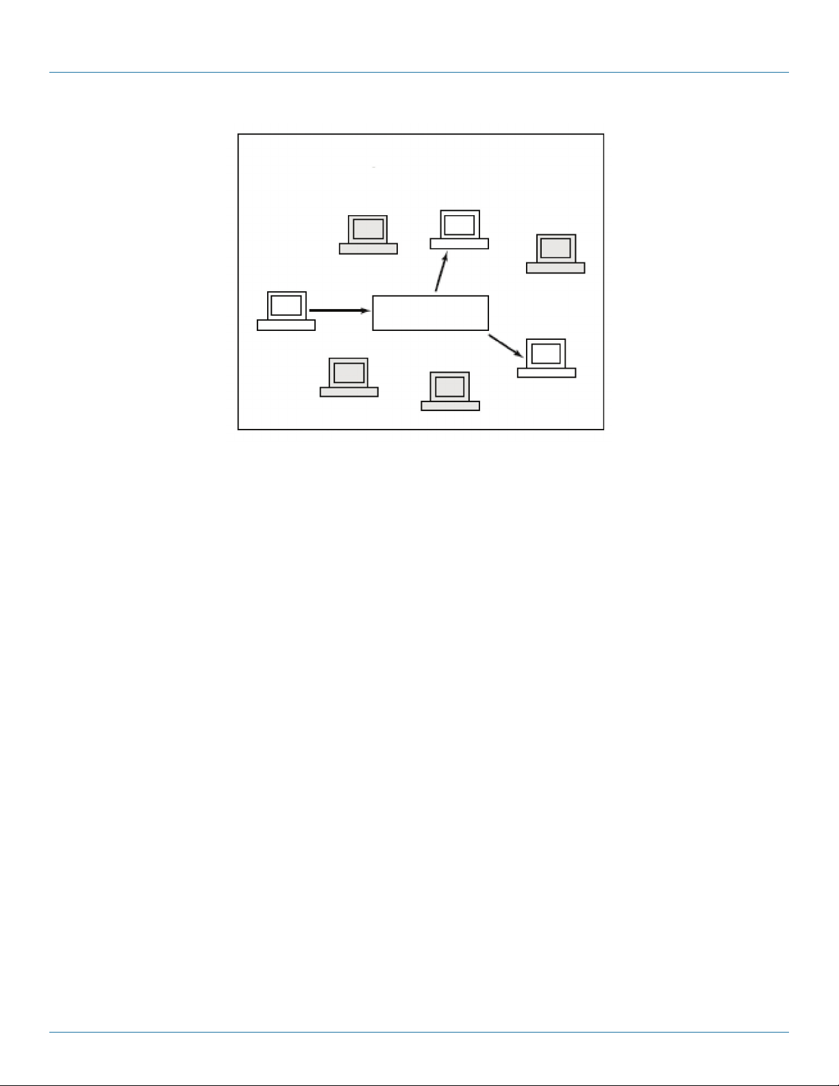
(MLD host)
Switch
Chapter 6: Configuration
Listener
Figure 6-32. MLD snooping enabled.
6.6.1 Basic Configuration
The section explains how to configure the MLD Snooping basic configuration and the parameters.
Web Interface
To configure the MLD Snooping Configuration in the Web interface:
1. Click “Configuration,” “MLD Snooping,” “Basic Configuration.”
2. Enable or disable the Global configuration parameters. Enable the port to join Router port and Fast Leave.
3. Scroll to select the Throttling mode with unlimited or 1 to 10.
4. Click “Save” to save the setting.
5. To cancel the setting, click the “Reset” button. It will revert to previously saved values.
LGB5028A User‘s Manual
724-746-5500 | blackbox.com
Page 83
Page 84

724-746-5500 | blackbox.com
Chapter 6: Configuration
Page 84
Figure 6-33. The MLD Snooping Basic Configuration screen.
724-746-5500 | blackbox.com
LGB5028A User‘s Manual
Page 85

Chapter 6: Configuration
Parameter Description
Snooping Enabled: Enable the Global MLD Snooping.
Unregistered IPMCv6 Flooding enabled: Enable unregistered IPMCv6 traffic flooding.
NOTE: Disabling unregistered IPMCv6 traffic flooding may lead to failure of Neighbor Discovery.
MLD SSM Range: SSM (Source-Specific Multicast) Range enables the SSM-aware hosts and routers to run the SSM service model
for the groups in the address (Using IPv6 Address) range.
Proxy Enabled: Enable MLD Proxy. Use to avoid forwarding unnecessary join and leave messages to the router side.
Port: The Port index for which you enable or disable the MLD Snooping function.
Router Port: Specify which ports act as router ports. A router port is a port on the Ethernet switch that leads towards the Layer
3 multicast device or MLD querier. If an aggregation member port is selected as a router port, the whole aggregation will act as a
router port.
Fast Leave: Enable the fast leave on the port.
Throttling: Enable to limit the number of multicast groups that a switch port can belong to.
Buttons:
Save: Click to save changes.
Reset: Click to undo any changes made locally and revert to previously saved values.
6.6.2 VLAN Configuration
When MLD snooping is enabled on a VLAN, the switch acts to minimize unnecessary multicast traffic. If the switch receives
multicast traffic destined for a given multicast address, it forwards that traffic only to ports on the VLAN that have MLD hosts for
that address. It drops that traffic for ports on the VLAN that have no MLD hosts.
The switch will use the last entry of the currently displayed entry as a basis for the next lookup. When the end is reached, the text
“No more entries” is shown in the displayed table. Use the button to start over.
Web Interface
To configure the MLD Snooping VLAN Configuration in the Web interface:
1. Click “Configuration,” “MLD Snooping,” “VLAN Configuration.”
2. Specify the VLAN ID with entries per page.
3. Click “ Refresh“ to refresh an entry of the MLD Snooping VLAN configuration Information.
4. Click “<< or >>” to move to a previous or next entry.
Figure 6-34. The MLD Snooping VLAN Configuration screen.
Parameter Description
VLAN ID: The VLAN ID of the entry.
LGB5028A User‘s Manual
724-746-5500 | blackbox.com
Page 85
Page 86

724-746-5500 | blackbox.com
Chapter 6: Configuration
Snooping Enabled: Enable the per-VLAN MLD Snooping. Select up to 32 VLANs.
MLD Querier: A router sends MLD Query messages onto a particular link. This router is called the querier. Enable the MLD
querier in the VLAN.
Compatibility: Compatibility is maintained by hosts and routers taking appropriate actions depending on the versions of MLD
operating on hosts and routers within a network. Select from MLD-Auto, Forced MLDv1, Forced MLDv2,. The default
compatibility value is MLD-Auto.
Rv: Show Robustness Variable. The Robustness Variable allows tuning for the expected packet loss on a network. The allowed
range is 1 to 255; the default value is 2.
QI: Query interval. The query interval is the interval between general queries sent by the querier. The allowed range is 1 to 31744
seconds; the default query interval is 125 seconds.
QRI: Query Response Interval. The maximum response delay used to calculate the maximum response code inserted into the
periodic general queries. The allowed range is 0 to 31744 in tenths of seconds; the default query response interval is 100 in tenths
of seconds (10 seconds).
LLQI (LMQI for IGMP): Show Last Listener Query Interval. The Last Listener Query Interval is the maximum response delay used
to calculate the maximum response code inserted into multicast address-specific queries sent in response to Version 1 multicast
listener done messages.
It is also the maximum response delay used to calculate the maximum response code inserted into multicast address and sourcespecific query messages. The allowed range is 0 to 31744 in tenths of seconds. The default last listener query interval is 10 in
tenths of seconds (1 second).
URI: Show the Unsolicited Report Interval. The Unsolicited Report Interval is the time between repetitions of a node's initial report
of interest in a multicast address. The allowed range is 0 to 31744 seconds; the default unsolicited report interval is 1 second.
Upper right icon (Refresh, <<, >> ): Click “Refresh” to refresh the IGMP Group Status by manual; use “<<” and “>>” to go
to the next/previous page or entry.
Buttons:
Save: Click to save changes.
Reset: Click to undo any changes made locally and revert to previously saved values.
6.6.3 Port Group Filtering
The section describes how to set the Port Group Filtering in the MLD Snooping function. Via the UI, you can add new filtering
groups and safety policies.
Web Interface
To configure the MLD Snooping Port Group Configuration in the Web interface:
1. Click “Configuration,” “MLD Snooping,” “Port Group Filtering Configuration.”
2. Click “Add new Filtering Group.”
3. Specify the Filtering Groups with entries per page.
4. Click the “Save” button to save the setting.
5. To cancel the setting, click the “Reset” button. It will revert to previously saved values.
724-746-5500 | blackbox.com
Page 86
LGB5028A User‘s Manual
Page 87

Chapter 6: Configuration
Figure 6-35. The MLD Snooping Port Group Filtering Configuration screen.
Parameter Description
Delete: Check to delete the entry. It will be deleted during the next save.
Port: Show the logical port for the settings. Choose the port you want to join a filtering group.
Filtering Groups: The IP Multicast Group that will be filtered.
Buttons:
Save: Click to save changes.
Reset: Click to undo any changes made locally and revert to previously saved values.
6.6.4 Status
The section describes how to display the MLD Snooping Status detailed information.
Web Interface
To display the MLD Snooping Status in the Web interface:
1. Click “Configuration,” “MLD Snooping,” “Status.”
2. Check the box to auto-refresh the information.
3. Click “Refresh” to refresh an entry of the MLD Snooping Status Information.
4. Click “Clear” to clear the MLD Snooping Status.
LGB5028A User‘s Manual
724-746-5500 | blackbox.com
Page 87
Page 88

724-746-5500 | blackbox.com
Chapter 6: Configuration
Figure 6-36. The MLD Snooping Status screen.
Parameter Description
VLAN ID: The VLAN ID of the entry.
Querier Version: Currently working querier version.
Host Version: Currenlty working host version.
Querier Status: Show the querier status as “ACTIVE” or “IDLE.”
Queries Transmitted: The number of transmitted queries.
Queries Received: The number of received queries.
724-746-5500 | blackbox.com
Page 88
LGB5028A User‘s Manual
Page 89
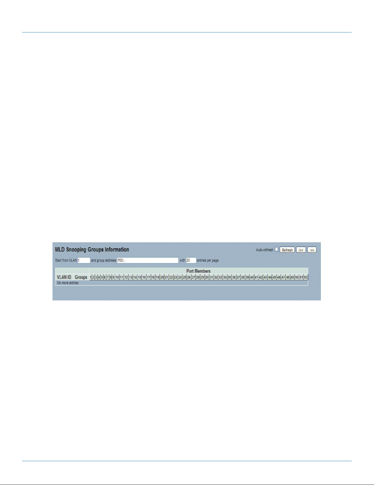
Chapter 6: Configuration
V1 Reports Received: The number of received V1 reports.
V2 Reports Received: The number of received V2 reports.
V1 Leaves Received: The number of received V1 leaves.
Auto-refresh: Check this box and the device will refresh the log automatically.
Upper right icon (Refresh, <<, >> ): You can click the “Refresh” button to manually refresh the IGMP Group Status. Use the
“<<” and “>>” buttons to go to the next/previous page or entry.
6.6.5 Group Information
The section describes how to set the MLD Snooping Groups Information. Choose the “Start from VLAN,", and ”group address”
input fields to select the starting point in the MLD Group table.
Each page shows up to 99 entries from the MLD Group table, and the default is 20, selected through the “entries per page”
input field. When first visited, the Web page will show the first 20 entries from the beginning of the MLD Group Table.
Web Interface
To display the MLD Snooping Group information in the Web interface:
1. Click “Configuration,” “MLD Snooping,” “Group Information.”
2. To auto-refresh the information, click the box next to “Auto-refresh.”
3. Click “Refresh” to refresh an entry of the MLD Snooping Group Information.
4. Click “Clear” to clear the MLD Snooping Groups information.
Figure 6-37. The MLD Snooping Groups Information screen.
Parameter Description
Navigating the MLD Group Table
Each page shows up to 99 entries from the MLD Group Table, and the default is 20, selected through the “entries per page”
input field. When first visited, the Web page will show the first 20 entries from the beginning of the MLD Group Table. The “Start
from VLAN” and “group address” input fields allow the user to select the starting point in the MLD Group Table. Clicking the
button will update the displayed table starting from that or the next closest MLD Group Table match. In addition, the two input
fields will—upon a button click—assume the value of the first displayed entry, allowing for continuous refresh with the same start
address. The switch will use the last entry of the currently displayed as a basis for the next lookup. When the end is reached, the
text “No more entries” is shown in the displayed table. Use the “Refresh” button to start over.
MLD Snooping Information Table Columns
VLAN ID: VLAN ID of the group.
Groups: Group address of the group displayed.
Port Members: Ports under this group.
Auto-refresh: Click on the auto-refresh icon and the device will refresh the log automatically.
LGB5028A User‘s Manual
724-746-5500 | blackbox.com
Page 89
Page 90

724-746-5500 | blackbox.com
Chapter 6: Configuration
Upper right icon (Refresh, <<, >> ): Click on the “Refresh” icon to manually refresh the IGMP Group Status; use the “<<” and
“ >>” keys to go to the next/previous page or entry..
6.6.6 IPv6 SSM Information
The section explains how to configure the Entries in the MLDv2 Information Table shown on this page. The MLDv2 Information
Table is sorted first by VLAN ID, then by group, and then by Port No. Different source addresses that belong to the same group
are treated as a single entry.
Each page shows up to 64 entries from the MLDv2 SSM (Source-Specific Multicast) Information table, and the default is 20,
selected through the “entries per page” input field. When first visited, the Web page will show the first 20 entries from the
beginning of the MLDv2 Information Table. The “Start from VLAN” and “Group” input fields allow the user to select the starting
point in the MLDv2 Information Table.
Web Interface
To display the MLDv2 IPv6 SSM Information in the Web interface:
1. Click “Configuration,” “MLD Snooping,” “IPv6 SSM Information.”
2. If you want to auto-refresh the information, click the box next to “Auto-refresh.”
3. Click ”Refresh” to refresh a MLDv2 IPv6 SSM Information entry.
4. Click “<<” and “ >>” to move to the previous or next entry.
Figure 6-38. The MLDv2 Information screen.
Parameter Description
MLDv2 Information Table Columns
VLAN ID: VLAN ID of the group.
Group: Group address of the group displayed.
Port No.: Switch port number.
Mode: Indicates the filtering mode maintained per VLAN ID, port number, or Group Address basis. The mode can be either
“Include” or “Exclude.”
Source Address: Show the IP address of the source. Currently, the system limits the total number of IP source addresses for
filtering to 128.
Typ e : Indicate the Type. It can be either “Allow” or “Deny.”
724-746-5500 | blackbox.com
Page 90
LGB5028A User‘s Manual
Page 91

Chapter 6: Configuration
6.7 MVR
The MVR feature enables multicast traffic forwarding on the Multicast VLAN. In a multicast television application, a PC or a
television with a set-top box can receive the multicast stream. Multiple set-top boxes or PCs can be connected to one subscriber
port, which is a switch port configured as an MVR receiver port. When a subscriber selects a channel, the set-top box or PC sends
an IGMP join message to Switch A to join the appropriate multicast. Uplink ports that send and receive multicast data to and
from the multicast VLAN are called MVR source ports.
6.7.1 Configuration
The section explains how to set switch’s the MVR basic configuration and parameters.
Web Interface
To configure the MVR Configuration in the Web interface:
1. Click “Configuration,” “MVR,” “Configuration.”
2. Scroll the MVR mode to enable or disable parameters.
3. Click the “Save” button to save the setting.
4. To cancel the setting, click the “Reset” button. It will revert to previously saved values.
LGB5028A User‘s Manual
724-746-5500 | blackbox.com
Page 91
Page 92

724-746-5500 | blackbox.com
Chapter 6: Configuration
Figure 6-39. The MVR Configuration screen.
Parameter Description
MVR Mode: Enable/Disable the Global MVR.
VLAN ID: Specify the Multicast VLAN ID.
Port: The physical switch port.
Mode: Enable MVR on the port.
Typ e : Specify the MVR port type on the port.
Immediate Leave: Enable the fast leave on the port.
724-746-5500 | blackbox.com
Page 92
LGB5028A User‘s Manual
Page 93

Chapter 6: Configuration
Buttons
Save: Click to save changes.
Reset: Click to undo any changes made locally and revert to previously saved values.
6.7.2 Groups Information
The section describes how to display the MVR Groups detail information on the switch. Entries in the MVR Group Table are
shown on this page. The MVR Group Table is sorted first by VLAN ID and then by group.
Web Interface
To display the MVR Groups Information in the Web interface:
1. Click “Configuration,” “MVR,” “Groups Information.”
2. To auto-refresh the information, click on the box next to “Auto-refresh.”
3. Click the “Refresh” button to refresh a entry in the MVR Groups Information.
4. Click “<<” and “ >>” buttons to move to the previous or next entry.
Parameter Description
MVR Group Table Columns
VLAN ID: VLAN ID of the group.
Groups: Group ID of the group displayed.
Port Members: Ports under this group.
Auto-refresh: Check the box next to auto-refresh and the device will refresh the information automatically.
Upper right icon (Refresh, <<, >> ): Click the “Refresh” button to manually refresh the MVR Group information. Use the “<<”
and “ >>” buttons to go to the next/previous page or entry.
6.7.3 Statistics
The section describes the MVR detail Statistics that will display after you have configured MVR on the switch.
Web Interface
To display the MVR Statistics Information in the Web interface:
1. Click “Configuration,” “MVR,” “Statistics.”
2. To auto-refresh the information, check the box next to “Auto-refresh.”
3. Click the “Refresh” button to refresh an MVR Statistics Information entry.
4. Click “<<” and “ >>” to move to the previous or next entry.
LGB5028A User‘s Manual
724-746-5500 | blackbox.com
Page 93
Page 94

724-746-5500 | blackbox.com
Chapter 6: Configuration
Figure 6-40. The MVR Statistics Information.
Parameter Description
VLAN ID: The Multicast VLAN ID.
V1 Reports Received: The number of received V1 reports.
V2 Reports Received: The number of received V2 reports.
V3 Reports Received: The number of received V3 reports.
V2 Leaves Received: The number of received V2 leaves.
Auto-refresh: Check the box next to “Auto-refresh” to refresh the information automatically.
Upper right icon (Refresh, <<, >> ): Click the “Refresh” button to manually refresh the MVR Group information. Use the “<<”
and “ >>” buttons to go to the next/previous page or entry.
6.8 LLDP
The switch supports LLDP. For current information on your switch model, the Link Layer Discovery Protocol (LLDP) provides a
standards-based method that enables switches to advertise and learn about adjacent LLDP devices. The Link Layer Discovery
Protocol (LLDP) is a vendor-neutral Link Layer protocol in the Internet Protocol Suite used by network devices for advertising their
identity, capabilities, and neighbors on a IEEE 802 local area network that’s principally wired Ethernet. The protocol is formally
referred to by the IEEE as Station and Media Access Control Connectivity Discovery specified in standards document IEEE 802.1AB.
6.8.1 LLDP Configuration
You can set each port to enable the LLDP configuration and the detail parameters, and the settings will take effect immediately.
This page enables the user to inspect and configure the current LLDP port settings.
Web Interface
To configure LLDP:
1. Click “LLDP configuration.”
2. Modify LLDP timing parameters.
3. Set the required mode for transmitting or receiving LLDP messages.
4. Specify the information to include in the TLV field of advertised messages.
5. Click “Save.”
724-746-5500 | blackbox.com
Page 94
LGB5028A User‘s Manual
Page 95

Chapter 6: Configuration
Figure 6-41. The LLDP Configuration screen.
Parameter Description
LLDP Parameters
Tx Inter val: The switch periodically transmits LLDP frames to its neighbors to update the network discovery information. The
interval between each LLDP frame is determined by the Tx Interval value. Valid values are restricted to 5–32768 seconds.
Tx Hold : Each LLDP frame contains information about how long the information in the LLDP frame is considered valid. The LLDP
information valid period is set to Tx Hold multiplied by Tx Interval seconds. Valid values are restricted to 2–10 times.
Tx Delay: If some configuration is changed (e.g. the IP address) a new LLDP frame is transmitted, but the time between the LLDP
frames will always be at least the value of Tx Delay seconds. Tx Delay cannot be larger than 1⁄4 of the Tx Interval value. Valid values
are restricted to 1–8192 seconds.
LGB5028A User‘s Manual
724-746-5500 | blackbox.com
Page 95
Page 96

724-746-5500 | blackbox.com
Chapter 6: Configuration
Tx Reinit: When a port is disabled, LLDP is disabled, or the switch is rebooted, an LLDP shutdown frame is transmitted to the
neighboring units, signaling that the LLDP information isn't valid anymore. Tx Reinit controls the amount of seconds between the
shutdown frame and a new LLDP initialization. Valid values are restricted to 1–10 seconds.
LLDP Port Configuration
The LLDP port settings relate to the currently selected port, as reflected by the page header.
Port: The switch port number of the logical LLDP port.
Mode: Select LLDP mode:
Rx only: The switch will not send out LLDP information, but LLDP information from neighbor units is analyzed.
Tx only: The switch will drop LLDP information received from neighbors, but will send out LLDP information.
Disabled: The switch will not send out LLDP information, and will drop LLDP information received from neighbors.
Enabled: The switch will send out LLDP information, and will analyze LLDP information received from neighbors.
CDP Aware: Select CDP awareness.
The CDP operation is restricted to decoding incoming CDP frames (the switch doesn't transmit CDP frames). CDP frames are only
decoded if LLDP on the port is enabled. Only CDP TLVs that can be mapped to a corresponding field in the LLDP neighbors’ table
are decoded. All other TLVs are discarded (unrecognized CDP TLVs and discarded CDP frames are not shown in the LLDP
statistics.). CDP TLVs are mapped onto LLDP neighbors’ table as shown below.
CDP TLV “Device ID” is mapped to the LLDP “Chassis ID” field.
CDP TLV “Address” is mapped to the LLDP “Management Address” field. The CDP address TLV can contain multiple addresses,
but only the first address is shown in the LLDP neighbors’ table.
CDP TLV ”Port ID” is mapped to the LLDP “Port ID” field.
CDP TLV “Version and Platform” is mapped to the LLDP “System Description” field.
Both the CDP and LLDP support “system capabilities,” but the CDP capabilities cover capabilities that are not part of the LLDP.
These capabilities are shown as “others” in the LLDP neighbors‘ table.
If all ports have CDP awareness disabled the switch forwards CDP frames received from neighbor devices. If at least one port has
CDP awareness enabled all CDP frames are terminated by the switch.
NOTE: When CDP awareness on a port is disabled, the CDP information isn't removed immediately. It is removed when the hold
time is exceeded.
Port Descr: Optional TLV: When checked, the “port description” is included in LLDP information transmitted.
Sys Name: Optional TLV: When checked, the “system name” is included in LLDP information transmitted.
Sys Descr: Optional TLV: When checked, the “system description” is included in LLDP information transmitted.
Sys Capa: Optional TLV: When checked, the “system capability” is included in LLDP information transmitted.
Mgmt Addr: Optional TLV: When checked, the “management address” is included in LLDP information transmitted.
Buttons:
Save: Click to save changes.
Reset: Click to undo any changes made locally and revert to previously saved values.
724-746-5500 | blackbox.com
Page 96
LGB5028A User‘s Manual
Page 97

Chapter 6: Configuration
6.8.2 LLDP Neighbors
This page provides a status overview for all LLDP neighbors. The displayed table contains a row for each port on which an LLDP
neighbor is detected. The columns hold the following information:
Web Interface
To show LLDP neighbors:
1. Click “LLDP Neighbors.”
2. Click “Refresh” for manual update Web screen.
3. Click “Auto-refresh” for auto-update Web screen.
Figure 6-42. The LLDP Neighbor Information screen.
NOTE: If your network without any device supports LLDP then the table will show “No LLDP neighbor information found.”
Parameter Description
Local Port: The port on which the LLDP frame was received.
Chassis ID: The Chassis ID is the identification of the neighbor’s LLDP frames.
Remote Port ID: The Remote Port ID is the identification of the neighbor port.
System Name: System Name is the name advertised by the neighbor unit.
Port Description: Port Description is the port description advertised by the neighbor unit.
System Capabilities:
System Capabilities describes the neighbor unit’s capabilities. The possible capabilities are:
1. Other
2. Repeater
3. Bridge
4. WLAN Access Point
5. Router
6. Telephone
7. DOCSIS cable device
8. Station only
9. Reserved
When a capability is enabled, the capability is followed by (+). If the capability is disabled, the capability is followed by (-).
System Description: System Description is the port description advertised by the neighbor unit.
LGB5028A User‘s Manual
724-746-5500 | blackbox.com
Page 97
Page 98

724-746-5500 | blackbox.com
Chapter 6: Configuration
Management Address: Management Address is the neighbor unit's address that is used for higher layer entities to assist
discovery by the network management. For example, this could hold the neighbor’s IP address.
Auto-refresh: Check the box to auto-refresh the device information.
Upper right icon (Refresh): Click this button to refresh the LLDP Neighbors information manually.
6.8.3 LLDP-MED Configuration
Media Endpoint Discovery is an enhancement of LLDP (known as LLDP-MED) that provides the following facilities:
• Auto-discovery of LAN policies (such as VLAN, Layer 2 priority, and differentiated services (Diffserv) settings, enabling plug-and-
play networking.
• Device location discovery to allow creation of location databases and, in the case of Voice over Internet Protocol (VoIP),
Enhanced 911 services.
• Extended and automated power management of Power over Ethernet (PoE) endpoints.
• Inventory management, enabling network administrators to track their network devices, and determine their characteristics
(manufacturer, software, and hardware versions, serial or asset number).
This page enables you to configure the LLDP-MED. This function applies to VoIP devices which support LLDP-MED.
Web Interface
To configure LLDP-MED:
1. Click “LLDP-MED configuration.”
2. Modify “Fast start repeat count parameter”; default is 4.
3. Modify “Coordinates Location” parameters.
4. Fill “Civic Address Location” parameters.
5. Add new policy.
6. Click “Save.” This will show Policy Port Configuration.
7. Select “Policy ID” for each port.
8. Click “Save.”
Page 98
724-746-5500 | blackbox.com
LGB5028A User‘s Manual
Page 99

Chapter 6: Configuration
Figure 6-43. The LLDP-MED Configuration screen.
Figure 6-44. Add New Policy screen.
Parameter Description
Fast start repeat count: Rapid startup and emergency call service location identification discovery of endpoints is a critically
important aspect of VoIP systems in general. Advertise only the information that is specifically relevant to particular endpoint types
(for example, only advertise the voice network policy to permitted voice-capable devices). This will conserve the limited LLDPDU
space and reduce security and system integrity issues.
LGB5028A User‘s Manual
724-746-5500 | blackbox.com
Page 99
Page 100

724-746-5500 | blackbox.com
Chapter 6: Configuration
LLDP-MED defines an LLDP-MED Fast Start interaction between the protocol and the application layers on top of the protocol so
it can achieve these related properties. Initially, a network connectivity device will only transmit LLDP TLVs in an LLDPDU. Only
after an LLDP-MED endpoint device is detected, will an LLDP-MED capable network connectivity device start to advertise LLDPMED TLVs in outgoing LLDPDUs on the associated port. The LLDP-MED application will temporarily speed up the transmission of
the LLDPDU to start within a second when a new LLDP-MED neighbor has been detected (so it can share LLDP-MED information
as fast as possible with new neighbors).
Because there is a risk of an LLDP frame being lost during transmission between neighbors, we recommend repeating the fast
start transmission multiple times to increase the possibility of the neighbors receiving the LLDP frame. With fast start repeat count,
you can specify the number of times the fast start transmission would be repeated. The recommended value is 4 times, given that
4 LLDP frames with a 1 second interval will be transmitted when an LLDP frame with new information is received.
NOTE: LLDP-MED and the LLDP-MED Fast Start mechanism is only intended to run on links between LLDP-MED network
connectivity devices and endpoint devices and does not apply to links between LAN infrastructure elements, including
network connectivity devices, or other types of links.
Coordinates Location
Latitude: Latitude SHOULD be normalized to within 0–90 degrees with a maximum of 4 digits. You can specify the direction to
either north of the equator or south of the equator.
Longitude: Longitude SHOULD be normalized to within 0–180 degrees with a maximum of 4 digits. You can specify the
direction to either east of the prime meridian or west of the prime meridian.
Altitude: Altitude SHOULD be normalized to within -32767 to 32767 with a maximum of 4 digits. You can select between two
altitude types (floors or meters).
Meters: Representing meters of altitude defined by the vertical datum specified.
Floors: Representing altitude in a form more relevant in buildings that have different floor-to-floor dimensions. An altitude = 0.0 is
meaningful even outside a building, and represents ground level at the given latitude and longitude. Inside a building, 0.0
represents the floor level associated with ground level at the main entrance.
Map Datum:
The Map Datum is used for the coordinates given in these options:
Meridian Name: Greenwich.
NAD83/NAVD88: North American Datum 1983, CRS Code 4269, Prime Meridian Name: Greenwich; The associated vertical
datum is the North American Vertical Datum of 1988 (NAVD88). Use this datum pair when referencing locations on land, not
near tidal water (which would use Datum = NAD83/MLLW).
NAD83/MLLW: North American Datum 1983, CRS Code 4269, Prime Meridian Name: Greenwich; The associated vertical datum
is Mean Lower Low Water (MLLW). Use this datum pair when referencing locations on water/sea/ocean.
Civic Address Location
IETF Geopriv Civic Address based Location Configuration Information (Civic Address LCI).
Country code: The two-letter ISO 3166 country code in capital ASCII letters—Example: DK, DE or US.
State: National subdivisions (state, canton, region, province, prefecture).
County: County, parish, gun (Japan), and district.
City: City, township, shi (Japan)—Example: Copenhagen.
City district: City division, borough, city district, ward, chou (Japan).
Block (Neighborhood): Neighborhood, block.
Street: Street—Example: Poppelvej.
724-746-5500 | blackbox.com
Page 100
LGB5028A User‘s Manual
 Loading...