

Page 1
WEB GUI USER MANUAL
LG B2118A-R 2, LGB2126A
GBE WEB
SMART
SWITCHES
24/7 TECHNICAL SUPPORT AT 1.877.877.2269 OR VISIT BL ACK BOX.COM
26-PORT GbE
WEB SMART SWITCH
Reset
System
1 2 3 4 5 6 7 8 9 10 11 12 13 14 15 16 17 18 19 20 21 22 23 24
25 26
Page 2

NEED HELP?
LEAV E TH E TEC H TO US
LIVE 24/7
TABLE OF CONTENTS
TECHNICAL
SUPPORT
1. 87 7.8 77. 22 69
ABOUT THIS MANUAL ...................................................................................................................................................................... 8
RELATED PUBLICATIONS ................................................................................................................................................................. 9
REVISION HISTORY .......................................................................................................................................................................... 9
INTRODUCTION ............................................................................................................................................................................... 10
Over vie w ........................................................................................................................................................................................................ 10
Manual Structure .......................................................................................................................................................................................... 10
1. OPERATION OF WEB-BASED MANAGEMENT .......................................................................................................................... 11
Initial Configuration ...................................................................................................................................................................................... 11
2. FIRST-TIME WIZARD ................................................................................................................................................................... 12
3. SYSTEM ........................................................................................................................................................................................ 14
3.1 System Information ................................................................................................................................................................................ 14
3.2 IP Address ...............................................................................................................................................................................................15
3.3 IP Settings ............................................................................................................................................................................................... 15
3.3.1 Advanced IP Settings ...................................................................................................................................................................................... 16
3.3.2 Status .................................................................................................................................................................................................................18
3.4 System Time ........................................................................................................................................................................................... 20
3.5 LLDP ........................................................................................................................................................................................................23
3.5.1 LLDP Configuration ..........................................................................................................................................................................................23
3.5.2 LLDP MED Configuration ...............................................................................................................................................................................25
3.5.3 LLDP Neighbor ................................................................................................................................................................................................30
3.5.4 LLDP MED Neighbor ........................................................................................................................................................................................31
3.5.5 LLDP Statistics .................................................................................................................................................................................................34
3.6 U PnP ........................................................................................................................................................................................................ 36
4. PORT MANAGEMENT ................................................................................................................................................................. 37
4.1 Port Configuration ..................................................................................................................................................................................37
4.2 Port Statistics ......................................................................................................................................................................................... 38
4.3 SFP Port Info ..........................................................................................................................................................................................40
4.4 Energy Efficient Ethernet .......................................................................................................................................................................42
4.5 Link Aggregation ....................................................................................................................................................................................43
4.5.1 Por t ......................................................................................................................................................................................................................43
4.5.2 Aggregator View ...............................................................................................................................................................................................44
4.5.3 Aggregation Hash Mode ................................................................................................................................................................................45
4.5.4 LACP System Priority ......................................................................................................................................................................................46
4.6 Loop Protection ......................................................................................................................................................................................47
4.6.1 Configuration .....................................................................................................................................................................................................47
4.6.2 Status .................................................................................................................................................................................................................49
2
1. 8 77. 87 7. 2 2 6 9 BL ACK BOX .COM
Page 3

NEED HELP?
LEAV E TH E TEC H TO US
LIVE 24/7
TABLE OF CONTENTS
TECHNICAL
SUPPORT
1. 87 7.8 77. 22 69
5. VLAN MANAGEMENT ................................................................................................................................................................. 50
5.1 VLAN Configuration ...............................................................................................................................................................................50
5.2 VLAN Membership ................................................................................................................................................................................. 53
5.3 VLAN Port Status ...................................................................................................................................................................................54
5.4 VLAN Selective QinQ Configuration ............................................................................................................ .........................................56
5.5 MAC-Based VLAN ..................................................................................................................................................................................57
5.5.1 Configuration .....................................................................................................................................................................................................57
5.5.2 Status .................................................................................................................................................................................................................58
5.6 Protocol-Based VLAN ............................................................................................................................................................................59
5.6.1 Protocol to Group .............................................................................................................................................................................................59
5.6.2 Group to VLAN ..................................................................................................................................................................................................60
5.7 IP Subnet-Based VLAN .......................................................................................................................................................................... 61
5.8 Private VLAN ..........................................................................................................................................................................................62
5.9 Port Isolation ..........................................................................................................................................................................................64
5.10 Voice VLAN ........................................................................................................................................................................................... 65
5.10 .1 C o n f iguration ...................................................................................................................................................................................................65
5.10 . 2 O U I ..................................................................................................................................................................................................................... 67
6. QUALITY OF SERVICE ................................................................................................................................................................. 68
6.1 Global Settings .......................................................................................................................................................................................68
6.2 Port Settings ........................................................................................................................................................................................... 69
6.3 Port Policing ........................................................................................................................................................................................... 70
6.4 Port Shaper ............................................................................................................ .................................................................................71
6.5 Storm Control ......................................................................................................................................................................................... 72
6.6 Port Scheduler ........................................................................................................................................................................................73
6.7 CoS/802.1p Mapping .............................................................................................................................................................................74
6.8 Cos/802.1p Remarking ..........................................................................................................................................................................75
6.9 IP Precedence Mapping .........................................................................................................................................................................76
6.10 IP Precedence Remarking ...................................................................................................................................................................77
6.11 DSCP Mapping ......................................................................................................................................................................................77
6.12 DSCP Remarking ..................................................................................................................................................................................78
7. SPANNING TREE .......................................................................................................................................................................... 80
7.1 S t a te .........................................................................................................................................................................................................80
7.2 Region Config .........................................................................................................................................................................................81
7.3 Instance View..........................................................................................................................................................................................82
8. MAC ADDRESS TABLES .............................................................................................................................................................. 88
8.1 Configuration ..........................................................................................................................................................................................88
8.2 Information .............................................................................................................................................................................................89
1. 8 7 7. 8 7 7. 2 2 6 9 BL ACK BO X.COM
3
Page 4

NEED HELP?
LEAV E TH E TEC H TO US
LIVE 24/7
TABLE OF CONTENTS
9. MULTICAST ................................................... ............................................................................................................................... 91
9.1 IGMP Snooping .......................................................................................................................................................................................91
9.1.1 Basic Configuration ..........................................................................................................................................................................................91
9.1.2 VLAN Configuration .........................................................................................................................................................................................93
9.1.3 Status ..................................................................................................................................................................................................................94
9.1.4 Group Information ............................................................................................................................................................................................95
9.1.5 IGMP SFM Information ....................................................................................................................................................................................96
9.2 MLD Snooping ........................................................................................................................................................................................98
9.2.1 Basic Configuration..........................................................................................................................................................................................99
9.2.2 VLAN Configuration ......................................................................................................................................................................................100
9.2.3 Status ...............................................................................................................................................................................................................101
9.2.4 Groups Information........................................................................................................................................................................................102
9.2.5 MLD SFM Information ...................................................................................................................................................................................103
9.3 MVR .......................................................................................................................................................................................................10 4
9.3.1 Basic Configuration........................................................................................................................................................................................104
9.3.2 Status ...............................................................................................................................................................................................................106
9.3.3 MVR Groups Information .............................................................................................................................................................................107
9.3.4 MVR SFM Information ..................................................................................................................................................................................108
9.4 Multicast Filtering Profile .................................................................................................................................................................... 110
9.4.1 Filtering Profile Table ..................................................................................................................................................................................... 110
9.4.2 Filtering Address Entry .................................................................................................................................................................................. 112
TECHNICAL
SUPPORT
1. 87 7.8 77. 22 69
10. D H C P .........................................................................................................................................................................................113
10.1 Snooping .............................................................................................................................................................................................113
10.1.1 C onfiguration ................................................................................................................................................................................................. 113
10.1.2 Snooping Table .............................................................................................................................................................................................11 4
10.1.3 Detailed Statistics.........................................................................................................................................................................................115
10.2 Relay .................................................................................................................................................................................................... 116
10.2.1 Configuration ................................................................................................................................................................................................116
10.2.2 Statistics ........................................................................................................................................................................................................11 7
10.3 Server .................................................................................................................................................................................................. 118
10.4 Server Status ...................................................................................................................................................................................... 120
11. S E C U R I T Y ................................................................................................................................................................................. 121
11.1 Management .......................................................................................................................................................................................12 1
11.1.1 Account ...........................................................................................................................................................................................................121
11.1.2 Privilege Levels ..............................................................................................................................................................................................12 2
11.1.3 Auth Method ..................................................................................................................................................................................................123
11.1.4 Access Management ...................................................................................................................................................................................124
11.2 IEEE 802.1X .........................................................................................................................................................................................126
11.2.1 Configuration .................................................................................................................................................................................................126
11.2.2 Status ..............................................................................................................................................................................................................130
4
1. 8 7 7. 8 7 7. 2 2 6 9 BL ACK BO X.COM
Page 5

NEED HELP?
LEAV E TH E TEC H TO US
LIVE 24/7
TABLE OF CONTENTS
TECHNICAL
SUPPORT
1. 87 7.8 77. 22 69
11.3 IP Source Guard ..................................................................................................................................................................................13 1
11.3.1 Configuration .................................................................................................................................................................................................131
11.3.2 Static Table ....................................................................................................................................................................................................132
11.3.3 Dynamic Table ..............................................................................................................................................................................................133
11.4 ARP Inspection ...................................................................................................................................................................................13 4
11.4.1 Port Configuration ........................................................................................................................................................................................134
11.4.2 VLAN Configuration .....................................................................................................................................................................................136
11.4.3 Static Table ....................................................................................................................................................................................................137
11.4.4 Dynamic Table ..............................................................................................................................................................................................138
11.5 Port Security .......................................................................................................................................................................................139
11.5.1 Configuration .................................................................................................................................................................................................139
11.5.2 Status ..............................................................................................................................................................................................................140
11.6 Radius ..................................................................................................................................................................................................142
11.6.1 Configuration .................................................................................................................................................................................................142
11.6.2 Status ..............................................................................................................................................................................................................143
11.7 TACACS+ .............................................................................................................................................................................................147
11.7.1 Configuration .................................................................................................................................................................................................147
12. ACCESS CONTROL .................................................................................................................................................................. 14 9
12.1 Access Control List ............................................................................................................................................................................14 9
12.2 Access Control Status .......................................................................................................................................................................15 3
13. SNMP ........................................................................................................................................................................................ 154
13.1 Configuration ......................................................................................................................................................................................15 4
13.2 S NMPv3 .............................................................................................................................................................................................. 155
13.2.1 Communities .................................................................................................................................................................................................155
13.2.2 Users ...............................................................................................................................................................................................................156
13.2.3 Groups ............................................................................................................................................................................................................157
13.2.4 Views ..............................................................................................................................................................................................................15 8
13.2.5 Access ............................................................................................................................................................................................................160
13.3 RMON Configuration ..........................................................................................................................................................................161
13.3.1 Statistics ........................................................................................................................................................................................................161
13.3.2 History ............................................................................................................................................................................................................162
13.3.3 Alarm ..............................................................................................................................................................................................................16 3
13.3.4 Event ...............................................................................................................................................................................................................16 4
13.4 RMON Status ......................................................................................................................................................................................16 6
13.4.1 Statistics ........................................................................................................................................................................................................166
13.4.2 History ............................................................................................................................................................................................................167
13.4.3 Alarm ..............................................................................................................................................................................................................16 8
13.4.4 Event ...............................................................................................................................................................................................................170
1. 8 7 7. 8 7 7. 2 2 6 9 BL ACK BO X.COM
5
Page 6

NEED HELP?
LEAV E TH E TEC H TO US
LIVE 24/7
TABLE OF CONTENTS
14. EVENT NOTIFICATION ............................................................................................................................................................ 17 1
14.1 SNMP Trap ..........................................................................................................................................................................................171
14.2 Syslog ..................................................................................................................................................................................................172
14.2.1 Syslog Configuration ...................................................................................................................................................................................17 2
14.2.2 View Log ........................................................................................................................................................................................................173
14.3 Event Configuration ...........................................................................................................................................................................174
15. DIAGNOSTICS .......................................................................................................................................................................... 176
15.1 PIN G ..................................................................................................................................................................................................... 17 6
15.2 Traceroute ...........................................................................................................................................................................................177
15.3 Cable Diagnostics ..............................................................................................................................................................................17 8
15.4 Mirror ...................................................................................................................................................................................................179
16. MAINTENANCE........................................................................................................................................................................ 181
16.1 Configuration ......................................................................................................................................................................................18 1
16.1.1 Save s t a r tup -co nf i g ......................................................................................................................................................................................181
16.1.2 Backup ............................................................................................................................................................................................................182
16.1.3 Restore ............................................................................................................................................................................................................182
16.1.4 Activate config ..............................................................................................................................................................................................183
16.1.5 Delete config ..................................................................................................................................................................................................184
16.2 Restart Device ....................................................................................................................................................................................185
16.3 Factory Defaults ................................................................................................................................................................................. 185
16.4 Firmware .............................................................................................................................................................................................186
16.4.1 Firmware Upgrade .......................................................................................................................................................................................186
16.4.2 Firmware Selection ......................................................................................................................................................................................186
TECHNICAL
SUPPORT
1. 87 7.8 77. 22 69
APPENDIX A. REGULATORY INFORMATION .............................................................................................................................. 18 8
A.1 FCC Statement .....................................................................................................................................................................................18 8
A.2 NOM Statement ................................................................................................................................................................................... 189
APPENDIX B. DISCLAIMER/TRADEMARKS ............................................................................................................................... 190
B.1 Disclaimer ............................................................................................................................................................................................. 190
B.2 Trademarks Used in this Manual ............................................................................................................ ............................................190
6
1. 8 7 7. 8 7 7. 2 2 6 9 BL ACK BO X.COM
Page 7

DE FAU LT SET TINGS
The switch’s default values are listed below:
IP Address: 192.16 8 .1.1
Subnet Mask: 255.255.255.0
Default Gateway: 192.168.1.254
Username: admin
Password: <none> (Just press the Enter key.)
NEED HELP?
LEAV E TH E TEC H TO US
LIVE 24/7
TECHNICAL
SUPPORT
1. 87 7.8 77. 22 69
1. 8 7 7. 8 7 7. 2 2 6 9 BL ACK BO X.COM
7
Page 8

NEED HELP?
LEAV E TH E TEC H TO US
LIVE 24/7
ABOUT THIS MANUAL
This GUI user guide gives specific information on how to operate and use the management functions of the LGB2118A-R2 or
LGB2126A via HTTP/HTTPs web browser.
The Manual is intended for use by network administrators who are responsible for operating and maintaining network equipment;
consequently, it assumes a basic working knowledge of general switch functions, the Internet Protocol (IP), and Hypertext Transfer
Protocol (HTTP).
TECHNICAL
SUPPORT
1. 87 7.8 77. 22 69
8
1. 8 7 7. 8 7 7. 2 2 6 9 BL ACK BO X.COM
Page 9

NEED HELP?
LEAV E TH E TEC H TO US
LIVE 24/7
RELATED PUBLICATIONS/REVISION HISTORY
TECHNICAL
SUPPORT
1. 87 7.8 77. 22 69
RELATED PUBLICATIONS
The following publications give specific information on how to operate and use the management functions of the switch:
Installation & Getting Started Guide
CLI User Guide
To download the guides from blackbox.com:
1. Go to www.blackbox.com
2. Enter the part number in the search box (for example, LGB2118A-R2 or LGB2126A).
3. Click on the product in the “Products” page.
4. Click on the “Support” tab on the product page and select the document you wish to download.
REVISION HISTORY
Current manual version: Revision A2, 11/17/2017
1. 8 7 7. 8 7 7. 2 2 6 9 BL ACK BO X.COM
9
Page 10

NEED HELP?
LEAV E TH E TEC H TO US
LIVE 24/7
INTRODUCTION
OVERVIEW
This User Guide explains how to install and connect your network system and configure and monitor the LGB2118A-R2 or
LGB2126A through the web via its serial interface and Ethernet ports. Detailed explanations of hardware and software functions
are shown as well as examples of web-based interface operation.
The LGB2118A-R2 or LGB2126A switch provides a reliable infrastructure for your business network. These switches deliver
intelligent features that improve the availability of your critical business applications, protect your sensitive information,
and optimize your network bandwidth to deliver information and applications more effectively. Each switch provides the ideal
combination of affordability and capabilities for entry level networking, including small business or enterprise applications,
and helps you create a more efficient, better-connected workforce.
LGB2118A-R2 or LGB2126A Web Managed Switches provide 18 or 26 ports in a single device.
L2+ features provide better manageability, security, QoS, and performance.
Support IPv4/IPv6 dual stack management
Support SSH/SSL secured management
Support SNMP v1/v2c/v3
Support RMON groups 1,2,3,9
Support IGMP v1/v2/v3 Snooping
Support MLD v1/v2 Snooping
Support RADIUS and TACACS+ authentication
Support IP Source Guard
Support DHCP Relay (Option 82)
Support DHCP Snooping
Support 802.1d (STP), 802.1w (RSTP) and 802.1s (MSTP)
Support LACP and static link aggregation
Support Q-in-Q double tag VLAN
TECHNICAL
SUPPORT
1. 87 7.8 77. 22 69
MANUAL STRUCTURE
Chapter 1: Operation of Web-based Management
Chapter 2: First Time Wizard
Chapter 3: System
Chapter 4: Port Management
Chapter 5: VLAN Management
Chapter 6: Quality of Service
Chapter 7: Spanning Tree
Chapter 8: MAC Address Tables
Chapter 9: Multicast
Chapter 10: DHCP
Chapter 11: Security
Chapter 12: Access Control
Chapter 13: SNMP
Chapter 14: Event Notification
Chapter 15: Diagnostics
Chapter 16: Maintenance
10
1. 8 7 7. 8 7 7. 2 2 6 9 BL ACK BO X.COM
Page 11

NEED HELP?
LEAV E TH E TEC H TO US
LIVE 24/7
CHAPTER 1: OPERATION OF WEB-BASED MANAGEMENT
INITIAL CONFIGURATION
This chapter explains how to configure and manage the LGB2118A-R2 or LGB2126A through the web user interface. With this
facility, you can easily access and monitor, through any one port of the switch, the status of the switch, including MIBs status, each
port activity, Spanning tree status, port aggregation status, multicast traffic, VLAN and priority status, even illegal access record
and so on.
The switch’s default values are listed below:
IP Address: 192.16 8 .1.1
Subnet Mask: 255.255.255.0
Default Gateway: 192.168.1.254
Username: admin
Password: <none> (Just press the Enter key.)
TECHNICAL
SUPPORT
1. 87 7.8 77. 22 69
After the LGB2118A-R2 or LGB2126A has finishes configuring its interface, you can browse it. For instance, type http://192.168.1.1
in the address row in a browser, and it will show the following screen and ask you to input username and password to login and
access authentication.
The default username is “admin” and password is empty. For first-time use, enter the default username and password, and then
click the <Login> button. The login process now is completed. In this login menu, you have to input the complete username
and password respectively, the LGB2118A-R2 or LGB2126A will not give you a shortcut to username automatically. This looks
inconvenient, but safer.
The LGB2118A-R2 or LGB2126A allows two or more users using administrator’s identity to manage this switch, the administrator
who does the last setting will be the available configuration in the system.
NOTE: When you log in to the Switch web page to manage the switch, you must first type the Username of the admin. The
password was blank, so after you type the Username, just press enter. You will see the management page.
When you log in to LGB2118A-R2 or LGB2126A series switch Web UI management interface, you can use both ipv4 ipv6.
To optimize the display effect, we recommend you use Microsoft IE 6.0 above, Netscape V7.1 above or Firefox V1.00 above with a
resolution of 1024 x 768. The switch supports a neutral web browser interface.
NOTE: The LGB2118A-R2 or LGB2126A has the function dhcp enabled, so If you do not have a DHCP server to provide ip
addresses to the switch, use the Switch default ip 192.168.1.1
FIGURE 1-1. LOGIN SCREEN
1. 8 7 7. 8 7 7. 2 2 6 9 BL ACK BO X.COM
11
Page 12
NEED HELP?
LEAV E TH E TEC H TO US
LIVE 24/7
CHAPTER 2: FIRST-TIME WIZARD
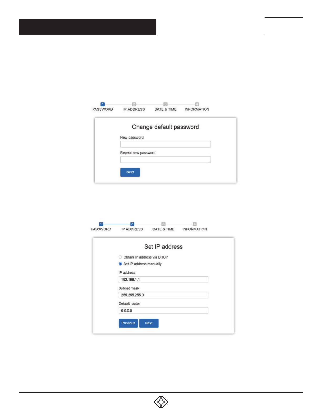
The first time you use this device you can configure some basic settings, such as password, IP address, date and time, and system
information.
Follow the procedure below:
Step 1: Change the default password
Configure the new password and enter it again, then press Next.
TECHNICAL
SUPPORT
1. 87 7.8 77. 22 69
FIGURE 2-1. CHANGE DEFAULT PASSWORD SCREEN
Step 2: Set the IP address
Select “obtain IP address via DHCP” or “Set IP address manually” to set the IP address.
12
FIGURE 2-2. CHANGE IP ADDRESS SCREEN
1. 8 7 7. 8 7 7. 2 2 6 9 BL ACK BO X.COM
Page 13
CHAPTER 1: HEADLINE
CHAPTER 2: FIRST-TIME WIZARD
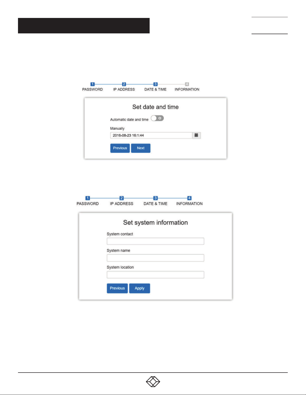
Step 3: Set the date and time
Enable “Automatic data and time” or select it manually to set the date and time.
NEED HELP?
LEAV E TH E TEC H TO US
LIVE 24/7
TECHNICAL
SUPPORT
1. 87 7.8 77. 22 69
FIGURE 2-3. SET DATE AND TIME SCREEN
Step 4: Set the system information
You can set some system information for this device, such as “System contact”, “System name”, “System location”.
FIGURE 2-4. SET SYSTEM INFORMATION SCREEN
1. 8 7 7. 8 7 7. 2 2 6 9 BL ACK BO X.COM
13
Page 14
NEED HELP?
LEAV E TH E TEC H TO US
LIVE 24/7
CHAPTER 1: HEADLINE
CHAPTER 3: SYSTEM
This chapter describes the basic configuration tasks, including the System Information and any management functions of the
Switch (e.g. Time, Account, IP, Syslog and NTP.)
3.1 SYSTEM INFORMATION
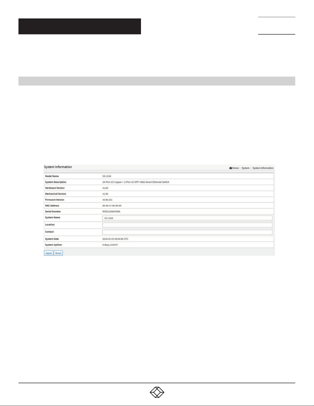
You can identify the system by configuring the contact information, name, and location of the switch.
The switch’s contact information is provided here.
WEB INTERFACE
To configure System Information in the web interface:
1. Click System and System Information.
2. Type in System Name, Location, Contact information in this page.
3. Click Apply.
TECHNICAL
SUPPORT
1. 87 7.8 77. 22 69
PARAMETER DESCRIPTION
Model Name: Displays the factory defined model name for identification purposes.
System Description: Displays the system description.
Hardware-Mechanical Version: The hardware and mechanical version of this switch.
Firmware Version: The software version of this switch.
MAC Address: The MAC Address of this switch.
Series Number: The serial number of this switch.
System name: An administratively assigned name for this managed node. By convention, this is the node’s fully-qualified domain
name. A domain name is a text string drawn from the alphabet (A-Z, a-z), digits (0-9), minus sign (-). No space characters are
permitted as part of a name. The first character must be an alpha character, and the first or last character must not be a minus
sign. The allowed string length is 0 to 128.
Location: The physical location of this node (e.g., telephone closet, 3rd floor). The allowed string length is 0 to 128, and the allowed
content is the ASCII characters from 32 to 1.
14
FIGURE 3-1. SYSTEM INFORMATION SCREEN
1. 8 7 7. 8 7 7. 2 2 6 9 BL ACK BO X.COM
Page 15
NEED HELP?
LEAV E TH E TEC H TO US
LIVE 24/7
CHAPTER 3: SYSTEM
TECHNICAL
SUPPORT
1. 87 7.8 77. 22 69
Contact: The textual identification of the contact person for this managed node, together with information on how to contact this
person. The allowed string length is 0 to 128, and the allowed content is the ASCII characters from 32 to 126.
System Date: The current (GMT) system time and date. The system time is obtained through the Timing server running on the
switch, if any.
System Uptime: The period of time the device has been operational.
Buttons
Apply: Click to save changes.
Reset: Click to undo any changes made locally and revert to previously saved values.
3.2 IP ADDRESS
The IPv4 address for the switch can be obtained via DHCP Server for VLAN 1. To manually configure an address, you need to
change the switch’s default settings to values that are compatible with your network. You may also need to establish a default
gateway between the switch and management stations that exist on another network segment.
3.3 IP SETTINGS
WEB INTERFACE
To configure the IP settings in the web interface:
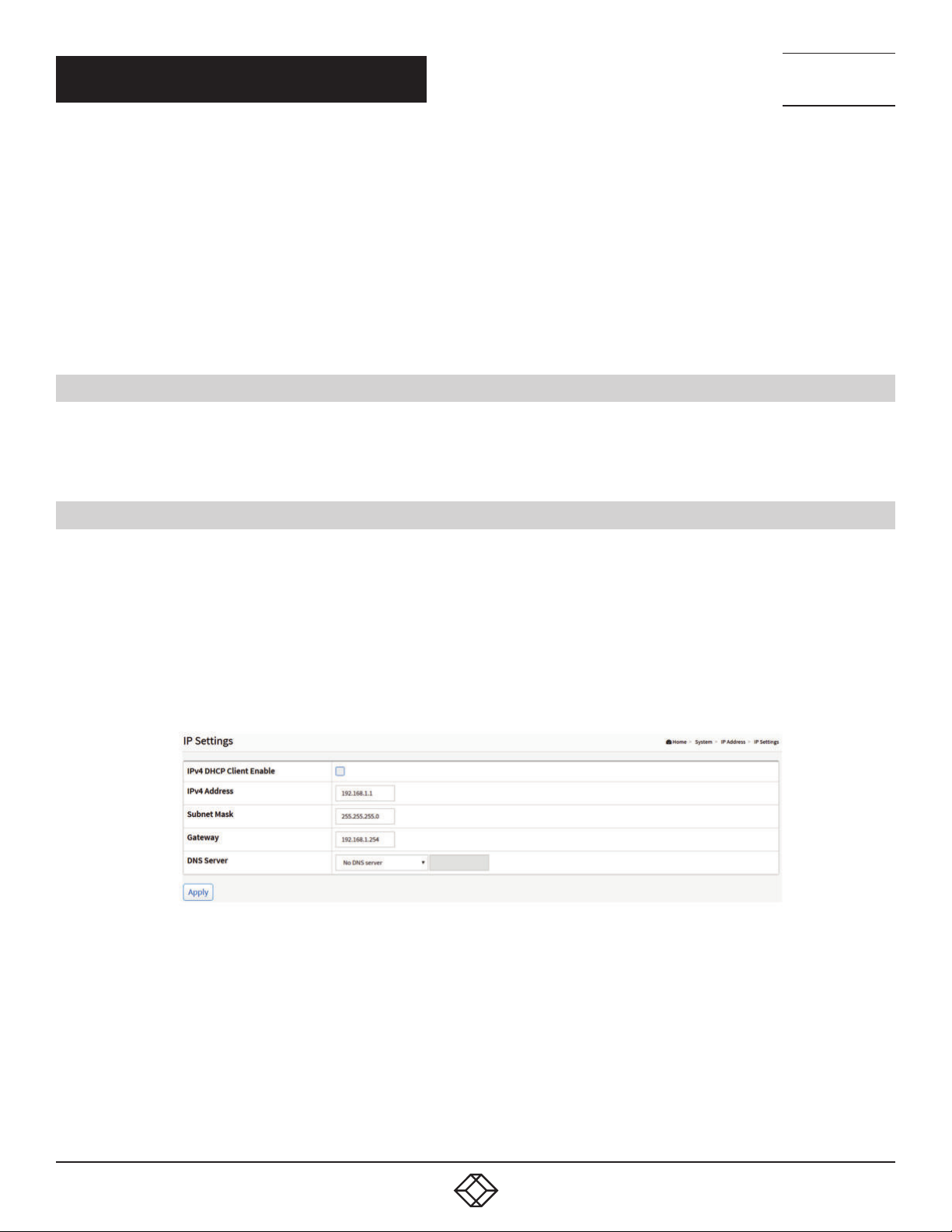
1. Click System, IP Address and IP Settings.
2. Enable or Disable the IPv4 DHCP Client.
3. Specify the IPv4 Address, Subnet Mask, Gateway.
4. Select DNS Server.
5. Click Apply.
FIGURE 3-2. IP SETTINGS SCREEN
PARAMETER DESCRIPTION
IPv4 DHCP Client Enable: Enable the DHCP client by checking this box. If this option is enabled, the system will configure the IPv4
address and mask of the interface using the DHCP protocol. The DHCP client will announce the configured System Name as
hostname to provide DNS lookup.
IPv4 Address: The IPv4 address of the interface in dotted decimal notation.
If DHCP is enabled, this field is not used. The field may also be left blank if IPv4 operation on the interface is not desired.
Subnet Mask: User IP subnet mask of the entry.
1. 8 7 7. 8 7 7. 2 2 6 9 BL ACK BO X.COM
15
Page 16
NEED HELP?
LEAV E TH E TEC H TO US
LIVE 24/7
CHAPTER 3: SYSTEM
Gateway: The IP address of the IP gateway. The valid format is dotted decimal notationor a valid IPv6 notation. Gateway and
Network must be of the same type.
DNS Server: This setting controls the DNS name resolution done by the switch. The following modes are supported:
- No DNS server: No DNS server will be used.
- Configured: Explicitly provide the IP address of the DNS Server in dotted decimal notation.
- From this DHCP interface: Specify from which DHCP-enabled interface a provided DNS server should be preferred.
- From any DHCP interfaces: The first DNS server offered from a DHCP lease to a DHCP-enabled interface will be used.
Buttons
Apply: Click to save changes.
TECHNICAL
SUPPORT
1. 87 7.8 77. 22 69
3.3.1 ADVANCED IP SETTINGS
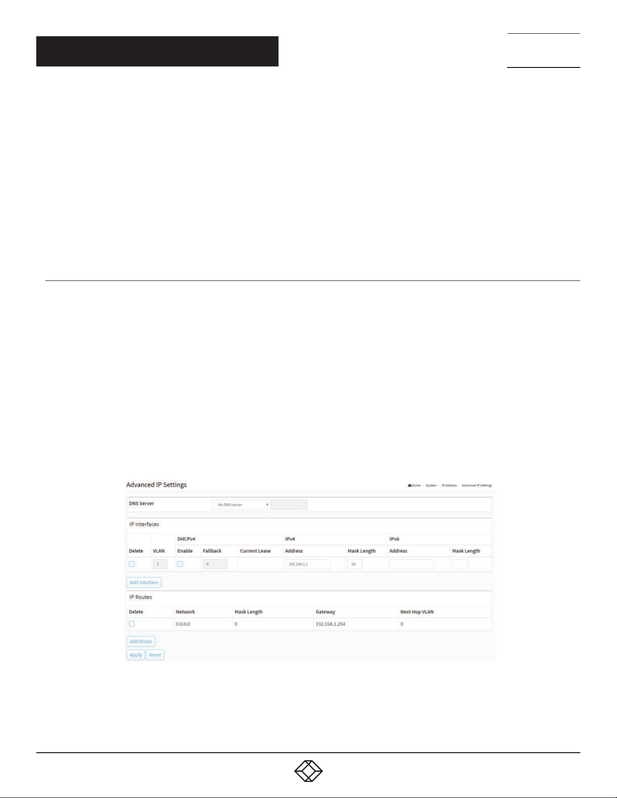
Configure the switch-managed IP information on this page.
Configure IP basic settings, control IP interfaces and IP routes.
The maximum number of interfaces supported is 8 and the maximum number of routes is 8.
WEB INTERFACE
To configure an Advanced IP Settings in the web interface:
1. Click System, IP Address and Advanced IP Settings.
2. Click Add Interface, then you can create a new Interface on the switch.
3. Click Add Route, then you can create a new Route on the switch.
4. Click Apply.
16
FIGURE 3-3.ADVANCED IP SETTINGS SCREEN
1. 8 7 7. 8 7 7. 2 2 6 9 BL ACK BO X.COM
Page 17

NEED HELP?
LEAV E TH E TEC H TO US
LIVE 24/7
CHAPTER 3: SYSTEM
TECHNICAL
SUPPORT
1. 87 7.8 77. 22 69
PARAMETER DESCRIPTION
IP Configuration
DNS Server: This setting controls the DNS name resolution done by the switch. The following modes are supported:
- No DNS server: No DNS server will be used.
- Configured: Explicitly provide the IP address of the DNS Server in dotted decimal notation.
- From this DHCP interface: Specify from which DHCP-enabled interface a provided DNS server should be preferred.
- From any DHCP interfaces: The first DNS server offered from a DHCP lease to a DHCP-enabled interface will be used.
IP Interfaces
Delete: Select this option to delete an existing IP interface.
VLAN: The VLAN associated with the IP interface. Only ports in this VLAN will be able to access the IP interface. This field is only
available for input when creating a new interface.
IPv4 DHCP Enabled: Enable the DHCP client by checking this box. If this option is enabled, the system will configure the IPv4
address and mask of the interface using the DHCP protocol. The DHCP client will announce the configured System Name as
hostname to provide DNS lookup.
IPv4 DHCP Fallback Timeout: The number of seconds for trying to obtain a DHCP lease. After this period expires, a configured IPv4
address will be used as IPv4 interface address. A value of zero disables the fallback mechanism, so that DHCP will keep retrying
until a valid lease is obtained. Legal values are 0 to 4294967295 seconds.
IPv4 DHCP Current Lease: For DHCP interfaces with an active lease, this column shows the current interface address, as provided
by the DHCP server.
IPv4 Address: The IPv4 address of the interface in dotted decimal notation.
If DHCP is enabled, this field is not used. The field may also be left blank if IPv4 operation on the interface is not desired.
IPv4 Mask: The IPv4 network mask, in number of bits (prefix length). Valid values are between 0 and 30 bits for a IPv4 address.
If DHCP is enabled, this field is not used. The field may also be left blank if IPv4 operation on the interface is not desired.
IPv6 Address: The IPv6 address of the interface. An IPv6 address is in 128-bit records represented as eight fields of up to four
hexadecimal digits with a colon separating each field (:). For example, fe80::215:c5ff:fe03:4dc7. The symbol :: is a special syntax that
can be used as a shorthand way of representing multiple 16-bit groups of contiguous zeros; but it can appear only once. It can also
represent a legally valid IPv4 address. For example, ::192.1.2.34. The field may be left blank if IPv6 operation on the interface is not
desired.
IPv6 Mask: The IPv6 network mask, in number of bits (prefix length). Valid values are between 1 and 128 bits for a IPv6 address. The
field may be left blank if IPv6 operation on the interface is not desired.
IP Routes
Delete: Select this option to delete an existing IP route.
Network: The destination IP network or host address of this route. A valid format is dotted decimal notation or a valid IPv6 notation.
A default route can use the value 0.0.0.0 or IPv6 :: notation.
Mask Length: The destination IP network or host mask, in number of bits (prefix length). It defines how much of a network address
that must match to qualify for this route. Valid values are between 0 and 32 bits respectively, 128 for IPv6 routes. Only a default
route will have a mask length of 0 (as it will match anything).
Gateway: The IP address of the IP gateway. A valid format is dotted decimal notation or a valid IPv6 notation. Gateway and Network
must be of the same type.
1. 8 7 7. 8 7 7. 2 2 6 9 BL ACK BO X.COM
17
Page 18

NEED HELP?
LEAV E TH E TEC H TO US
LIVE 24/7
CHAPTER 3: SYSTEM
Next Hop VLAN (Only for IPv6): The VLAN ID (VID) of the specific IPv6 interface associated with the gateway. The given VID ranges
from 1 to 4094 and will be effective only when the corresponding IPv6 interface is valid. If the IPv6 gateway address is link-local, it
must specify the next hop VLAN for the gateway. If the IPv6 gateway address is not link-local, the system ignores the next hop VLAN
for the gateway.
Buttons
Add Interface: Click to add a new IP interface. A maximum of 8 interfaces is supported.
Add Route: Click to add a new IP route. A maximum of 8 routes is supported.
Apply: Click to save changes.
Reset: Click to undo any changes made locally and revert to previously saved values.
TECHNICAL
SUPPORT
1. 87 7.8 77. 22 69
3.3.2 STATUS
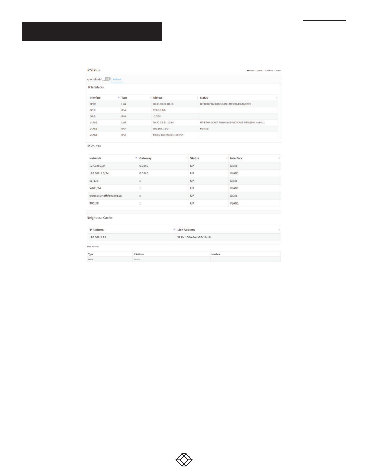
This page displays the status of the IP protocol layer. The status is defined by the IP interfaces, the IP routes and the neighbor
cache (ARP cache) status.
WEB INTERFACE
To display the log configuration in the web interface:
1. Click System, IP Address and Status.
2. Display the IP Configuration information.
18
1. 8 7 7. 8 7 7. 2 2 6 9 BL ACK BO X.COM
Page 19
CHAPTER 3: SYSTEM
NEED HELP?
LEAV E TH E TEC H TO US
LIVE 24/7
TECHNICAL
SUPPORT
1. 87 7.8 77. 22 69
FIGURE 3-4. IP STATUS SCREEN
PARAMETER DESCRIPTION
IP Interfaces
Interface: Show the name of the interface.
Type: Show the address type of the entry. This may be LINK or IPv4.
Address: Show the current address of the interface (of the given type).
Status: Show the status flags of the interface (and/or address).
IP Routes
Network: Show the destination IP network or host address of this route.
Gateway: Show the gateway address of this route.
Status: Show the status flags of the route.
Interface: Show the name of the interface.
1. 8 7 7. 8 7 7. 2 2 6 9 BL ACK BO X.COM
19
Page 20

CHAPTER 3: SYSTEM
Neighbor cache
IP Address: Show the IP address of the entry.
Link Address: Show the Link (MAC) address for which a binding to the IP address given exists.
DNS Server
Type: Show the address type of the entry. This may be LINK or IPv4.
IP Address: Show the current address of the interface (of the given type).
Interface: Show the name of the interface.
Buttons
Auto-refresh: Check this box to refresh the page automatically. Automatic refresh occurs every 3 seconds.
Refresh: Click to refresh the page immediately.
3.4 SYSTEM TIME
NEED HELP?
LEAV E TH E TEC H TO US
LIVE 24/7
TECHNICAL
SUPPORT
1. 87 7.8 77. 22 69
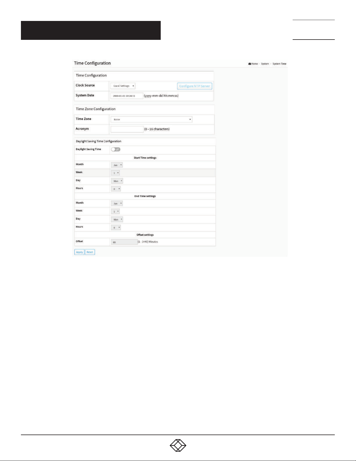
The switch provides manual and automatic ways to set the system time via NTP. The manual setting is simple: just input “Year”,
“Month”, “Day”, “Hour” and “Minute” within the valid value range indicated in each item.
WEB INTERFACE
To configure Time in the web interface:
1. Click System and System Time
2. Specify the Time parameter.
3. Click Apply.
20
1. 8 7 7. 8 7 7. 2 2 6 9 BL ACK BO X.COM
Page 21
CHAPTER 3: SYSTEM
NEED HELP?
LEAV E TH E TEC H TO US
LIVE 24/7
TECHNICAL
SUPPORT
1. 87 7.8 77. 22 69
FIGURE 3-5. TIME CONFIGURATION SCREEN
PARAMETER DESCRIPTION
Time Configuration
Clock Source: There are two modes for configuring where the Clock Source is from. Select “Local Settings”: Clock Source from Local
Time. Select “NTP Server”: Clock Source from NTP Server.
System Date: Show the current time of the system. The year of system date is between 2000 and 2037.
Time Zone Configuration
Time Zone: Lists various Time Zones worldwide. Select the appropriate Time Zone from the drop-down box and click Apply to set.
Acronym: The User can set the acronym of the time zone. This is a User configurable acronym to identify the time zone. (Range: Up
to 16 characters).
Daylight Saving Time Configuration
Daylight Saving Time: This is used to set the clock forward or backward according to the configurations set below for a defined
Daylight Saving Time duration. Select ‘Disable’ to disable the Daylight Saving Time configuration. Select ‘Recurring’ and configure
the Daylight Saving Time duration to repeat the configuration every year. Select ‘Non-Recurring’ and configure the Daylight Saving
Time duration for single time configuration. (Default: Disabled).
1. 8 7 7. 8 7 7. 2 2 6 9 BL ACK BO X.COM
21
Page 22
CHAPTER 3: SYSTEM
Recurring Configuration
Start time settings:
- Week - Select the starting week number.
- Day - Select the starting day.
- Month - Select the starting month.
- Hours - Select the starting hour.
End time settings:
- Week - Select the ending week number.
- Day - Select the ending day.
- Month - Select the ending month.
- Hours - Select the ending hour.
Offset settings:
Offset - Enter the number of minutes to add during Daylight Saving Time. (Range: 1 to 1440)
NEED HELP?
LEAV E TH E TEC H TO US
LIVE 24/7
TECHNICAL
SUPPORT
1. 87 7.8 77. 22 69
NOTE: Under “Start Time Settings” and “End Time Settings” displays what you set in the “Start Time Settings” and “End Time
Settings” field information.
Buttons
Apply: Click to save changes.
Reset: Click to undo any changes made locally and revert to previously saved values.
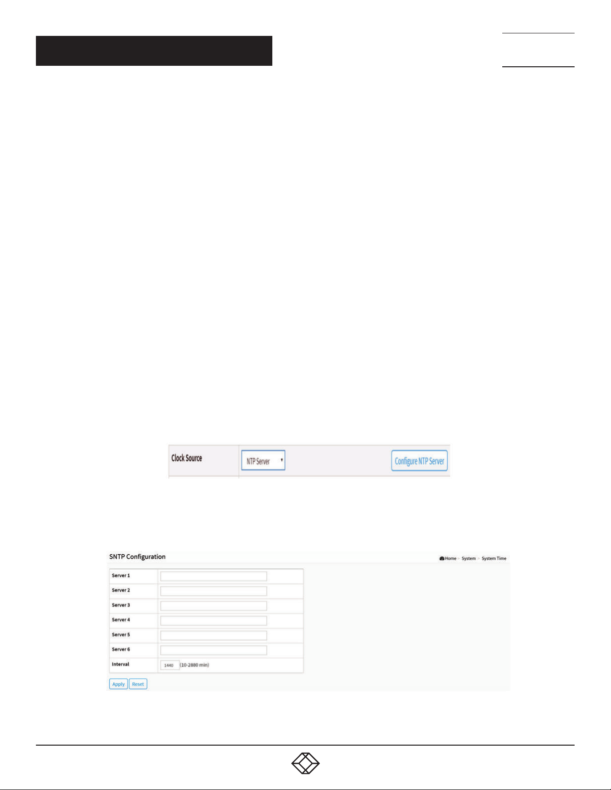
FIGURE 3-6. CONFIGURE NTP SERVER BUTTON
Configure NTP Server: Click to configure NTP server when Clock Source is selected from NTP Server.
22
FIGURE 3-7. SNTP CONFIGURATION
1. 8 7 7. 8 7 7. 2 2 6 9 BL ACK BO X.COM
Page 23

NEED HELP?
LEAV E TH E TEC H TO US
LIVE 24/7
CHAPTER 3: SYSTEM
NTP is Network Time Protocol and is used to sync the network time based Greenwich Mean Time (GMT). If you use the NTP mode
and select a built-in NTP time server or manually specify a user-defined NTP server as well as Time Zone, the switch will sync
the time shortly after pressing the <Apply> button. Though it synchronizes the time automatically, NTP does not update the time
periodically without user’s processing.
Time Zone is an offset time of GMT. You have to select the time zone first and then perform time sync via NTP because the switch
will combine this time zone offset and updated NTP time to result in the local time; otherwise, you will not able to get the correct
time. The switch supports a configurable time zone from -12 to +13 step 1 hour.
Default Time zone: +8 Hrs.
Parameter description:
Server 1 to 6: Provide the NTP IPv4 or IPv6 address of this switch. IPv6 address is in 128-bit records represented as eight fields of
up to four hexadecimal digits with a colon separating each field (:). For example, ‘fe80::215:c5ff:fe03:4dc7’. The symbol ‘::’ is a special
syntax that can be used as a shorthand way of representing multiple 16-bit groups of contiguous zeros, but it can only appear once.
It can also represent a legally valid IPv4 address. For example, ‘::192.1.2.34’.
Interval: You can specify the time interval in seconds after which a time check and, in case of deviation, a resynchronization of the
internal device clock against the specified timeserver via Network Time Protocol(NTP) should be performed.
Buttons
These buttons are displayed on the SNTP page:
Apply: Click to save changes.
Reset: Click to undo any changes made locally and revert to previously saved values.
TECHNICAL
SUPPORT
1. 87 7.8 77. 22 69
3.5 LLDP
The switch supports LLDP. For current information on your switch model, the Link Layer Discovery Protocol (LLDP) provides a
standards-based method for enabling switches to advertise themselves to adjacent devices and to learn about adjacent LLDP
devices. The Link Layer Discovery Protocol (LLDP) is a vendor-neutral Link Layer protocol in the Internet Protocol Suite used
by network devices for advertising their identity, capabilities, and neighbors on a IEEE 802 local area network, principally wired
Ethernet. The protocol is formally referred to by the IEEE as Station and Media Access Control Connectivity Discovery specified in
standards document IEEE 802.1AB.
3.5.1 LLDP CONFIGURATION
You can set the LLDP configuration and the detail parameters per port, and the settings will take effect immediately. This page
allows the user to inspect and configure the current LLDP port settings.
WEB INTERFACE
To configure LLDP:
1. Click System, LLDP and LLDP configuration.
2. Modify LLDP timing parameters.
3. Set the required mode for transmitting or receiving LLDP messages.
4. Specify the information to include in the TLV field of advertised messages.
5. Click Apply.
1. 8 7 7. 8 7 7. 2 2 6 9 BL ACK BO X.COM
23
Page 24
CHAPTER 3: SYSTEM
PARAMETER DESCRIPTION
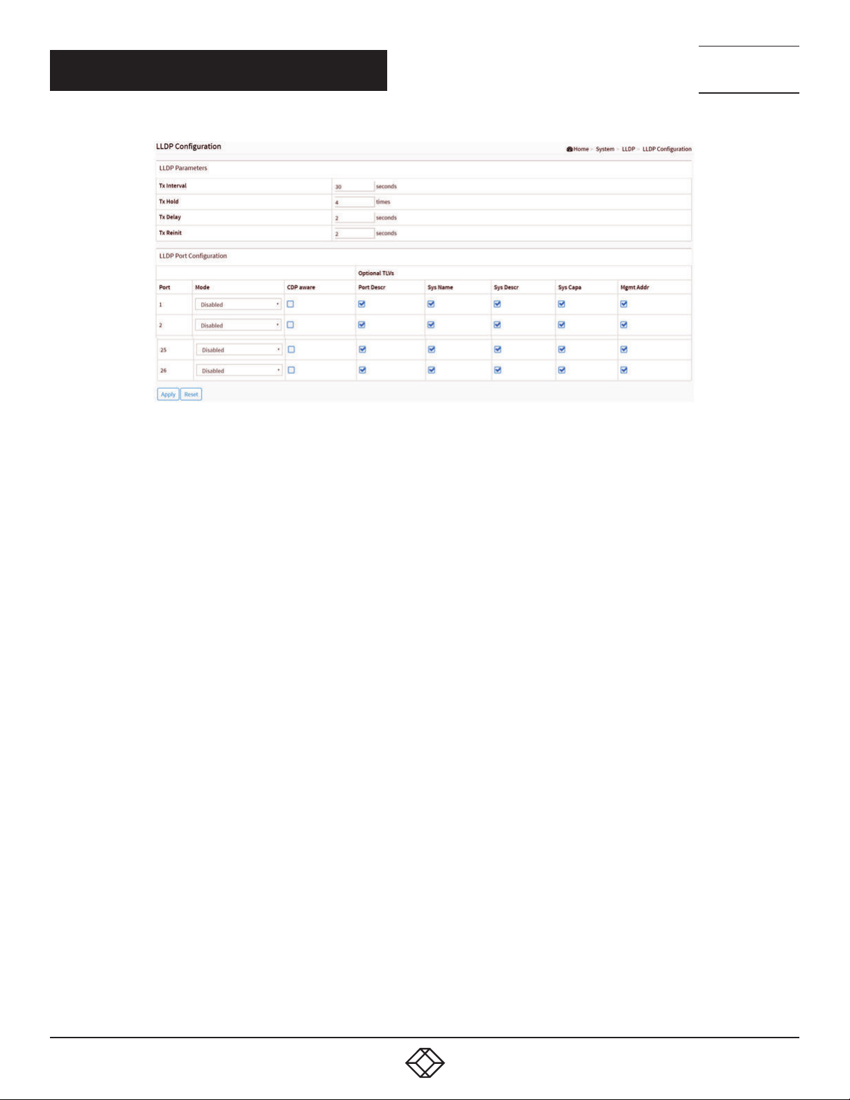
FIGURE 3-8. LLDP CONFIGURATION SCREEN
NEED HELP?
LEAV E TH E TEC H TO US
LIVE 24/7
TECHNICAL
SUPPORT
1. 87 7.8 77. 22 69
LLDP Parameters
Tx Interval: The switch periodically transmits LLDP frames to its neighbors for the network discovery information to be up-to-date. The
interval between each LLDP frame is determined by the Tx Interval value. Valid values are restricted to 5–32768 seconds.
Tx Hold: Each LLDP frame contains information about how long the information in the LLDP frame will be considered valid. The LLDP
information valid period is set to Tx Hold multiplied by Tx Interval seconds. Valid values are restricted to 2–10 times.
Tx Delay: If a configuration is changed (e.g. the IP address) a new LLDP frame is transmitted, but the time between the LLDP frames
will always be at least the value of Tx Delay seconds. Tx Delay cannot be larger than 1/4 of the Tx Interval value. Valid values are
restricted to 1–8192 seconds.
Tx Reinit: When a port is disabled, LLDP is disabled or the switch is rebooted, an LLDP shutdown frame is transmitted to the
neighboring units, signaling that the LLDP information isn’t valid anymore. Tx Reinit controls the amount of seconds between the
shutdown frame and a new LLDP initialization. Valid values are restricted to 1–10 seconds.
LLDP Port Configuration
The LLDP port settings relate to the currently selected, as reflected by the page header.
Port: The switch port number of the logical LLDP port.
Mode: Select LLDP mode.
- Rx only: The switch will drop LLDP information received from neighbors, but will send out LLDP information.
- Disabled: The switch will not send out LLDP information, and will drop LLDP information received from neighbors.
- Enabled: The switch will send out LLDP information, and will analyze LLDP information received from neighbors.
CDP Aware: Select CDP awareness.
The CDP operation is restricted to decode incoming CDP frames (The switch doesn’t transmit CDP frames). CDP frames are only
decoded if LLDP on the port is enabled.
- Only CDP TLVs that can be mapped to a corresponding field in the LLDP neighbors’ table are decoded. All other TLVs are discarded
(Unrecognized CDP TLVs and discarded CDP frames are not shown in the LLDP statistics.). CDP TLVs are mapped onto LLDP
neighbors’ table.
- CDP TLV “Device ID” is mapped to the LLDP “Chassis ID” field.
24
1. 8 7 7. 8 7 7. 2 2 6 9 BL ACK BO X.COM
Page 25

NEED HELP?
LEAV E TH E TEC H TO US
LIVE 24/7
CHAPTER 3: SYSTEM
TECHNICAL
SUPPORT
1. 87 7.8 77. 22 69
- CDP TLV “Address” is mapped to the LLDP “Management Address” field. The CDP address TLV can contain multiple addresses, but
only the first address is shown in the LLDP neighbors’ table.
- CDP TLV “Port ID” is mapped to the LLDP “Port ID” field.
- CDP TLV “Version and Platform” is mapped to the LLDP “System Description” field.
Both the CDP and LLDP support “system capabilities”, but the CDP capabilities cover capabilities that are not part of the LLDP. These
capabilities are shown as “others” in the LLDP neighbors’ table.
If all ports have CDP awareness disabled, the switch forwards CDP frames received from neighbor devices. If at least one port has
CDP awareness enabled, all CDP frames are terminated by the switch.
NOTE: When CDP awareness on a port is disabled, the CDP information isn’t removed immediately, but is removed when the hold
time is exceeded.
Port Descr: Optional TLV: When checked, the “port description” is included in LLDP information transmitted.
Sys Name: Optional TLV: When checked, the “system name” is included in LLDP information transmitted.
Sys Descr: Optional TLV: When checked, the “system description” is included in LLDP information transmitted.
Sys Capa: Optional TLV: When checked, the “system capability” is included in LLDP information transmitted.
Mgmt Addr: Optional TLV: When checked, the “management address” is included in LLDP information transmitted.
Buttons
Apply: Click to save changes.
Reset: Click to undo any changes made locally and revert to previously saved values.
3.5.2 LLDP MED CONFIGURATION
Media Endpoint Discovery is an enhancement of LLDP, known as LLDP-MED, that provides the following facilities:
Auto-discovery of LAN policies (such as VLAN, Layer 2 Priority and Differentiated services (Diffserv) settings) enabling plug and play
networking.
Device location discovery to allow creation of location databases and, in the case of Voice over Internet Protocol (VoIP), Enhanced 911
services.
Inventory management, allowing network administrators to track their network devices, and determine their characteristics
(manufacturer, software and hardware versions, and serial or asset number).
This page allows you to configure the LLDP-MED. This function applies to VoIP devices that support LLDP-MED.
WEB INTERFACE
To configure LLDP-MED:
1. Click System, LLDP and LLDP-MED Configuration.
2. Modify Fast start repeat count parameter; default is 4.
3. Modify Coordinates Location parameters.
4. Fill Civic Address Location parameters.
5. Add new policy.
6. Click Apply; this will show the following Policy Port Configuration.
7. Select Policy ID for each port.
8. Click Apply.
1. 8 7 7. 8 7 7. 2 2 6 9 BL ACK BO X.COM
25
Page 26
CHAPTER 3: SYSTEM
NEED HELP?
LEAV E TH E TEC H TO US
LIVE 24/7
TECHNICAL
SUPPORT
1. 87 7.8 77. 22 69
26
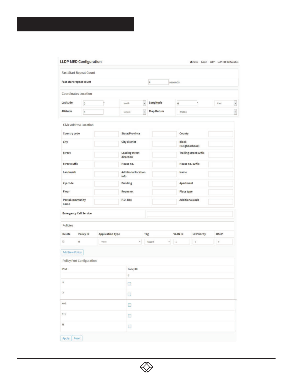
FIGURE 3-9. LLDP-MED CONFIGURATION
1. 8 7 7. 8 7 7. 2 2 6 9 BL ACK BO X.COM
Page 27

NEED HELP?
LEAV E TH E TEC H TO US
LIVE 24/7
CHAPTER 3: SYSTEM
TECHNICAL
SUPPORT
1. 87 7.8 77. 22 69
PARAMETER DESCRIPTION
Fast start repeat count:
Rapid startup and Emergency Call Service Location Identification Discovery of endpoints is a critically important aspect of VoIP systems
in general. In addition, it is best to advertise only those pieces of information that are specifically relevant to particular endpoint types (for
example, only advertise the voice network policy to permitted voice-capable devices), both in order to conserve the limited LLDPU space and
to reduce security and system integrity issues that can come with inappropriate knowledge of the network policy.
With this in mind LLDP-MED defines an LLDP-MED Fast Start interaction between the protocol and the application layers on top of the
protocol, in order to achieve these related properties. Initially, a Network Connectivity Device will only transmit LLDP TLVs in an LLDPDU. Only
after an LLDP-MED Endpoint Device is detected will an LLDP-MED capable Network Connectivity Device start to advertise LLDP-MED TLVs
in outgoing LLDPDUs on the associated port. The LLDP-MED application will temporarily speed up the transmission of the LLDPDU to start
within a second when a new LLDP-MED neighbor has been detected, to share LLDP-MED information as fast as possible to new neighbors.
Because there is a risk of an LLDP frame being lost during transmission between neighbors, we recommend repeating the fast start
transmission multiple times to increase the possibility of the neighbors receiving the LLDP frame. With Fast start repeat count, you can
specify the number of times the fast start transmission will be repeated. The recommended value is 4 times, given that 4 LLDP frames with
a 1 second interval will be transmitted when an LLDP frame with new information is received.
NOTE: The LLDP-MED and the LLDP-MED Fast Start mechanism is only intended to run on links between LLDP-MED Network Connectivity
Devices and Endpoint Devices, so it does not apply to links between LAN infrastructure elements, including Network Connectivity Devices, or
other types of links.
Coordinates Location
Latitude: Latitude SHOULD be normalized to within 0-90 degrees with a maximum of 4 digits. You can specify the direction to either
North of the equator or South of the equator.
Longitude: Longitude SHOULD be normalized to within 0-180 degrees with a maximum of 5 digits. You can specify the direction to
either East of the prime meridian or West of the prime meridian.
Altitude: Altitude SHOULD be normalized to within -32767 to 32767 with a maximum of 4 digits. You can select between two
altitude types (floors or meters).
Meters: Representing meters of Altitude defined by the vertical datum specified.
Floors: Representing altitude in a form more relevant in buildings that have different floor-to-floor dimensions. An altitude = 0.0 is
meaningful even outside a building, and represents ground level at the given latitude and longitude. Inside a building, 0.0 represents
the floor level associated with ground level at the main entrance.
Map Datum: The Map Datum is used for the coordinates given in these options:
- WGS84: (Geographical 3D) - World Geodesic System 1984, CRS Code 4327, and Prime Meridian Name: Greenwich.
- NAD83/NAVD88: North American Datum 1983, CRS Code 4269, Prime Meridian Name: Greenwich; the associated vertical datum
is the North American Vertical Datum of 1988 (NAVD88). This datum pair is to be used when referencing locations on land, not
near tidal water (which would use Datum = NAD83/MLLW).
- NAD83/MLLW: North American Datum 1983, CRS Code 4269, Prime Meridian Name: Greenwich; the associated vertical datum is
Mean Lower Low Water (MLLW). This datum pair is to be used when referencing locations on water/sea/ocean.
Civic Address Location:
IETF Geopriv Civic Address based Location Configuration Information (Civic Address LCI).
Country code: The two-letter ISO 3166 country code in capital ASCII letters - Example: DK, DE or US.
State: National subdivisions (state, canton, region, province, prefecture).
County: County, parish, gun (Japan), district.
City: City, township, shi (Japan) - Example: Copenhagen.
City district: City division, borough, city district, ward, chou (Japan).
Block (Neighborhood): Neighborhood, block.
1. 8 7 7. 8 7 7. 2 2 6 9 BL ACK BO X.COM
27
Page 28

NEED HELP?
LEAV E TH E TEC H TO US
LIVE 24/7
CHAPTER 3: SYSTEM
Street: Street - Example: Poppelvej.
Leading street direction: Leading street direction - Example: N.
Trailing street suffix: Trailing street suffix - Example: SW.
Street suffix: Street suffix - Example: Ave, Platz.
House no.: House number - Example: 21.
House no. suffix: House number suffix - Example: A, 1/2.
Landmark: Landmark or vanity address - Example: Columbia University.
Additional location info: Additional location info - Example: South Wing.
Name: Name (residence and office occupant) - Example: Flemming Jahn.
Zip code: Postal/zip code - Example: 2791.
Building: Building (structure) - Example: Low Library.
Apartment: Unit (Apartment, suite) - Example: Apt 42.
Floor: Floor - Example: 4.
Room no.: Room number - Example: 450F.
Place type: Place type - Example: Office.
Postal community name: Postal community name - Example: Leonia.
P.O. Box: Post office box (P.O. BOX) - Example: 12345.
Additional code: Additional code - Example: 1320300003.
Emergency Call Service: Emergency Call Service (e.g. E911 and others), such as defined by TIA or NENA.
Emergency Call Service: Emergency Call Service ELIN identifier data format is defined to carry the ELIN identifier as used
during emergency call setup to a traditional CAMA or ISDN trunk-based PSAP. This format consists of a numerical digit string,
corresponding to the ELIN to be used for emergency calling.
Policies
Network Policy Discovery enables the efficient discovery and diagnosis of mismatch issues with the VLAN configuration, along with
the associated Layer 2 and Layer 3 attributes, that apply for a set of specific protocol applications on that port. Improper network policy
configurations are a very significant issue in VoIP environments that frequently result in voice quality degradation or loss of service.
Policies are only intended for use with applications that have specific ‘real-time’ network policy requirements, such as interactive voice and/
or video services.
The network policy attributes advertised are:
1. Layer 2 VLAN ID (IEEE 802.1Q-2003)
2. Layer 2 priority value (IEEE 802.1D-2004)
3. Layer 3 Diffserv code point (DSCP) value (IETF RFC 2474)
This network policy is potentially advertised and associated with multiple sets of application types supported on a given port. The application
types specifically addressed are:
1. Voice
2. Guest Voice
3. Softphone Voice
4. Video Conferencing
5. Streaming Video
6. Control / Signalling (conditionally support a separate network policy for the media types above)
TECHNICAL
SUPPORT
1. 87 7.8 77. 22 69
28
1. 8 7 7. 8 7 7. 2 2 6 9 BL ACK BO X.COM
Page 29

NEED HELP?
LEAV E TH E TEC H TO US
LIVE 24/7
CHAPTER 3: SYSTEM
TECHNICAL
SUPPORT
1. 87 7.8 77. 22 69
A large network may support multiple VoIP policies across the entire organization, and different policies per application type. LLDP-MED allows
multiple policies to be advertised per port, each corresponding to a different application type. Different ports on the same Network Connectivity
Device may advertise different sets of policies, based on the authenticated user identity or port configuration.
It should be noted that LLDP-MED is not intended to run on links other than between Network Connectivity Devices and Endpoints, and
therefore does not need to advertise the multitude of network policies that frequently run on an aggregated link interior to the LAN.
Delete: Check to delete the policy. It will be deleted during the next save.
Policy ID: ID for the policy. This is auto generated and shall be used when selecting the polices that shall be mapped to the specific
ports.
Application Type: Intended use of the application types:
1. Voice - for use by dedicated IP Telephony handsets and other similar appliances supporting interactive voice services. These devices
are typically deployed on a separate VLAN for ease of deployment and enhanced security by isolation from data applications.
2. Voice Signaling (conditional) - for use in network topologies that require a different policy for the voice signaling than for the
voice media. This application type should not be advertised if all the same network policies apply as those advertised in the Voice
application policy.
3. Guest Voice - support a separate ‘limited feature-set’ voice service for guest users and visitors with their own IP Telephony handsets
and other similar appliances supporting interactive voice services.
4. Guest Voice Signaling (conditional) - for use in network topologies that require a different policy for the guest voice signaling than for
the guest voice media. This application type should not be advertised if all the same network policies apply as those advertised in the
Guest Voice application policy.
5. Softphone Voice - for use by softphone applications on typical data centric devices, such as PCs or laptops. This class of endpoints
frequently does not support multiple VLANs, if at all, and is typically configured to use an ‘untagged’ VLAN or a single ‘tagged’ data
specific VLAN. When a network policy is defined for use with an ‘untagged’ VLAN (see Tagged flag below), then the L2 priority field is
ignored and only the DSCP value has relevance.
6. Video Conferencing - for use by dedicated Video Conferencing equipment and other similar appliances supporting real-time
interactive video/audio services.
7. Streaming Video - for use by broadcast or multicast based video content distribution and other similar applications supporting
streaming video services that require specific network policy treatment. Video applications relying on TCP with buffering would not be
an intended use of this application type.
8. Video Signaling (conditional) - for use in network topologies that require a separate policy for the video signaling than for the
video media. This application type should not be advertised if all the same network policies apply as those advertised in the Video
Conferencing application policy.
Tag: Tag indicating whether the specified application type is using a ‘tagged’ or an ‘untagged’ VLAN.
Untagged indicates that the device is using an untagged frame format and so does not include a tag header as defined by IEEE
802.1Q-2003. In this case, both the VLAN ID and the Layer 2 priority fields are ignored and only the DSCP value is relevant.
Tagged indicates that the device is using the IEEE 802.1Q tagged frame format, and that both the VLAN ID and the Layer 2 priority
values are being used, as well as the DSCP value. The tagged format includes an additional field, known as the tag header. The tagged
frame format also includes priority tagged frames as defined by IEEE 802.1Q-2003.
VLAN ID: VLAN identifier (VID) for the port as defined in IEEE 802.1Q-2003.
L2 Priority: L2 Priority is the Layer 2 priority to be used for the specified application type. L2 Priority may specify one of eight priority
levels (0 through 7), as defined by IEEE 802.1D-2004. A value of 0 represents use of the default priority as defined in IEEE 802.1D-
2004.
DSCP: DSCP value to be used to provide Diffserv node behaviour for the specified application type as defined in IETF RFC 2474. DSCP
may contain one of 64 code point values (0 through 63). A value of 0 represents use of the default DSCP value as defined in RFC 2475.
1. 8 7 7. 8 7 7. 2 2 6 9 BL ACK BO X.COM
29
Page 30
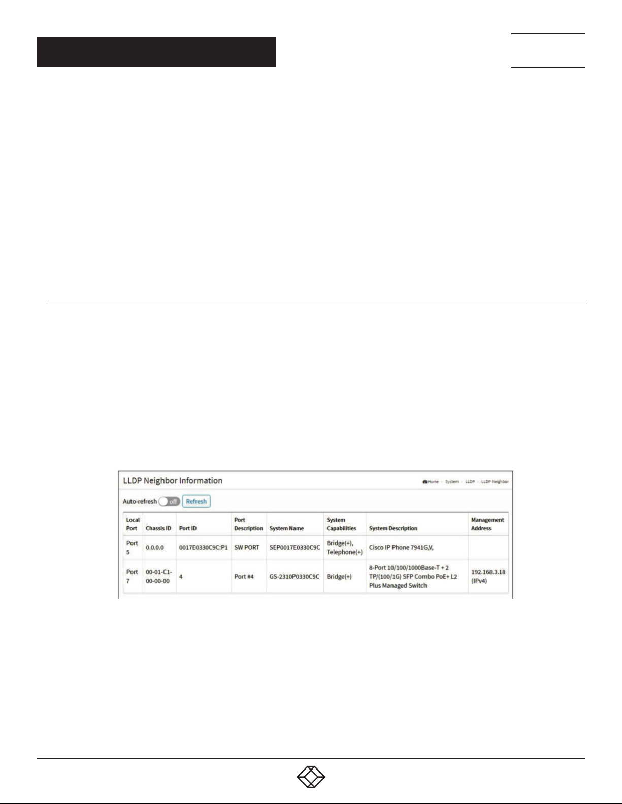
NEED HELP?
LEAV E TH E TEC H TO US
LIVE 24/7
CHAPTER 3: SYSTEM
Port Policies Configuration: Every port may advertise a unique set of network policies or different attributes for the same network
policies, based on the authenticated user identity or port configuration.
Port: The port number to which the configuration applies.
Policy Id: The set of policies that will apply to a given port. The set of policies is selected by check marking the checkboxes that
corresponds to the policies.
Buttons
Adding a new policy: Click to add a new policy. Specify the Application type, Tag, VLAN ID, L2 Priority and DSCP for the new policy.
Click “Apply”.
Apply: Click to save changes.
Reset: Click to undo any changes made locally and revert to previously saved values.
TECHNICAL
SUPPORT
1. 87 7.8 77. 22 69
3.5.3 LLDP NEIGHBOR
This page provides a status overview for all LLDP neighbors. The displayed table contains a row for each port on which an LLDP
neighbor is detected. The columns hold the following information:
WEB INTERFACE
To show LLDP neighbors:
1. Click System, LLDP and LLDP Neighbor.
2. Click Refresh for manual update web screen.
3. Click Auto-refresh for auto-update web screen.
FIGURE 3-10. LLDP NEIGHBOR INFORMATION
PARAMETER DESCRIPTION
Local Port: The port on which the LLDP frame was received.
Chassis ID: The Chassis ID is the identification of the neighbor’s LLDP frames.
Port ID: The Remote Port ID is the identification of the neighbor port.
Port Description: Port Description is the port description advertised by the neighbor unit.
System Name: System Name is the name advertised by the neighbor unit.
30
1. 8 7 7. 8 7 7. 2 2 6 9 BL ACK BO X.COM
Page 31

NEED HELP?
LEAV E TH E TEC H TO US
LIVE 24/7
CHAPTER 3: SYSTEM
System Capabilities: System Capabilities describes the neighbor unit’s capabilities. The possible capabilities are:
1. Other
2. Repeater
3. Bridge
4. WLAN Access Point
5. Router
6. Telephone
7. DOCSIS cable device
8. Station only
9. Reserved
When a capability is enabled, the capability is followed by (+). If the capability is disabled, the capability is followed by (-).
System Description: Displays the system description.
Management Address: Management Address is the neighbor unit’s address that is used for higher layer entities to assist discovery
by the network management. This could, for instance, hold the neighbor’s IP address.
Buttons
Auto-refresh: Check this box to refresh the page automatically. Automatic refresh occurs every 3 seconds.
Refresh: Click to refresh the page immediately.
TECHNICAL
SUPPORT
1. 87 7.8 77. 22 69
3.5.4 LLDP-MED NEIGHBOR
This page provides a status overview of all LLDP-MED neighbors. The displayed table contains a row for each port on which
an LLDP neighbor is detected. This function applies to VoIP devices that support LLDP-MED. The columns hold the following
information:
WEB INTERFACE
To show LLDP-MED neighbor:
1. Click System, LLDP and LLDP-MED Neighbor.
2. Click Refresh for manual update web screen.
3. Click Auto-refresh for auto-update web screen.
1. 8 7 7. 8 7 7. 2 2 6 9 BL ACK BO X.COM
31
Page 32
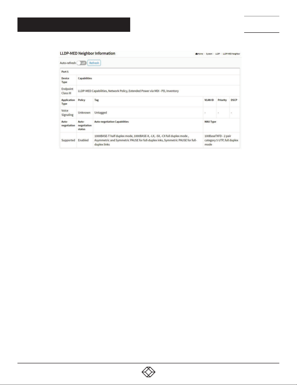
CHAPTER 3: SYSTEM
NEED HELP?
LEAV E TH E TEC H TO US
LIVE 24/7
TECHNICAL
SUPPORT
1. 87 7.8 77. 22 69
FIGURE 3-11. LLDP-MED NEIGHBOR INFORMATION
NOTE: If there is no device that supports LLDP-MED in your network, then the table will show “No LLDP-MED neighbor information
found”.
PARAMETER DESCRIPTION
Port: The port on which the LLDP frame was received.
Device Type: LLDP-MED Devices are comprised of two primary Device Types: Network Connectivity Devices and Endpoint Devices.
LLDP-MED Network Connectivity Device Definition
LLDP-MED Network Connectivity Devices, as defined in TIA-1057, provide access to the IEEE 802 based LAN infrastructure for
LLDP-MED Endpoint Devices. An LLDP-MED Network Connectivity Device is a LAN access device based on any of the following
technologies:
1. LAN Switch/Router
2. IEEE 802.1 Bridge
3. IEEE 802.3 Repeater (included for historical reasons)
4. IEEE 802.11 Wireless Access Point
5. Any device that supports the IEEE 802.1AB and MED extensions defined by TIA-1057 and can relay IEEE 802 frames via any
method.
LLDP-MED Endpoint Device Definition:
LLDP-MED Endpoint Devices, as defined in TIA-1057, are located at the IEEE 802 LAN network edge, and participate in IP
communication service using the LLDP-MED framework.
Within the LLDP-MED Endpoint Device category, the LLDP-MED scheme is broken into further Endpoint Device Classes, as defined
in the following.
Each LLDP-MED Endpoint Device Class is defined to build upon the capabilities defined for the previous Endpoint Device Class.
For-example, any LLDP-MED Endpoint Device claiming compliance as a Media Endpoint (Class II) will also support all aspects of
TIA-1057 applicable to Generic Endpoints (Class I), and any LLDP-MED Endpoint Device claiming compliance as a Communication
Device (Class III) will also support all aspects of TIA-1057 applicable to both Media Endpoints (Class II) and Generic Endpoints (Class
I).
32
1. 8 7 7. 8 7 7. 2 2 6 9 BL ACK BO X.COM
Page 33

NEED HELP?
LEAV E TH E TEC H TO US
LIVE 24/7
CHAPTER 3: SYSTEM
LLDP-MED Generic Endpoint (Class I): The LLDP-MED Generic Endpoint (Class I) definition is applicable to all endpoint products that
require the base LLDP discovery services defined in TIA-1057, but do not support IP media or act as an end-user communication
appliance. Such devices may include (but are not limited to) IP Communication Controllers, other communication related servers, or
any device requiring basic services as defined in TIA-1057.
Discovery services defined in this class include LAN configuration, device location, network policy, power management, and inventory
management.
LLDP-MED Media Endpoint (Class II): The LLDP-MED Media Endpoint (Class II) definition is applicable to all endpoint products that
have IP media capabilities however may or may not be associated with a particular end user. Capabilities include all of the capabilities
defined for the previous Generic Endpoint Class (Class I), and are extended to include aspects related to media streaming. Example
product categories expected to adhere to this class include (but are not limited to) Voice / Media Gateways, Conference Bridges,
Media Servers, and similar.
Discovery services defined in this class include media-type-specific network layer policy discovery.
LLDP-MED Communication Endpoint (Class III): The LLDP-MED Communication Endpoint (Class III) definition is applicable to all
endpoint products that act as end user communication appliances supporting IP media. Capabilities include all of the capabilities
defined for the previous Generic Endpoint (Class I) and Media Endpoint (Class II) classes, and are extended to include aspects
related to end user devices. Example product categories expected to adhere to this class include (but are not limited to) end user
communication appliances, such as IP Phones, PC-based softphones, or other communication appliances that directly support the
end user.
Discovery services defined in this class include provision of location identifier (including ECS / E911 information), embedded L2 switch
support, inventory management.
LLDP-MED Capabilities: LLDP-MED Capabilities describes the neighborhood unit’s LLDP-MED capabilities. The possible capabilities
are:
1. LLDP-MED capabilities
2. Network Policy
3. Location Identification
4. Extended Power via MDI - PSE
5. Extended Power via MDI - PD
6. Inventory
7. Rese r ve d
Application Type: Application Type indicating the primary function of the application(s) defined for this network policy, advertised by an
Endpoint or Network Connectivity Device. The possible application types are shown next.
1. Voice - for use by dedicated IP Telephony handsets and other similar appliances supporting interactive voice services. These devices
are typically deployed on a separate VLAN for ease of deployment and enhanced security by isolation from data applications.
2. Voice Signaling - for use in network topologies that require a different policy for the voice signaling than for the voice media.
3. Guest Voice - to support a separate limited feature-set voice service for guest users and visitors with their own IP Telephony
handsets and other similar appliances supporting interactive voice services.
4. Guest Voice Signaling - for use in network topologies that require a different policy for the guest voice signaling than for the guest
voice media.
5. Softphone Voice - for use by softphone applications on typical data centric devices, such as PCs or laptops.
6. Video Conferencing - for use by dedicated Video Conferencing equipment and other similar appliances supporting real-time
interactive video/audio services.
TECHNICAL
SUPPORT
1. 87 7.8 77. 22 69
1. 8 7 7. 8 7 7. 2 2 6 9 BL ACK BO X.COM
33
Page 34

NEED HELP?
LEAV E TH E TEC H TO US
LIVE 24/7
CHAPTER 3: SYSTEM
7. Streaming Video - for use by broadcast or multicast based video content distribution and other similar applications supporting
streaming video services that require specific network policy treatment. Video applications relying on TCP with buffering would not be
an intended use of this application type.
8. Video Signaling - for use in network topologies that require a separate policy for the video signaling than for the video media.
Policy: Policy indicates that an Endpoint Device wants to explicitly advertise that the policy is required by the device. Can be either
Defined or Unknown.
- Unknown: The network policy for the specified application type is currently unknown.
- Defined: The network policy is defined.
TAG: TAG is indicative of whether the specified application type is using a tagged or an untagged VLAN. Can be Tagged or Untagged.
- Untagged: The device is using an untagged frame format and as such does not include a tag header as defined by IEEE 802.1Q-2003.
- Tagged: The device is using the IEEE 802.1Q tagged frame format.
VLAN ID: VLAN ID is the VLAN identifier (VID) for the port as defined in IEEE 802.1Q-2003. A value of 1 through 4094 is used to define
a valid VLAN ID. A value of 0 (Priority Tagged) is used if the device is using priority tagged frames as defined by IEEE 802.1Q-2003,
meaning that only the IEEE 802.1D priority level is significant and the default PVID of the ingress port is used instead.
Priority: Priority is the Layer 2 priority to be used for the specified application type. One of the eight priority levels (0 through 7).
DSCP: DSCP is the DSCP value to be used to provide Diffserv node behavior for the specified application type as defined in IETF RFC
2474. Contain one of 64 code point values (0 through 63).
Auto-negotiation: Auto-negotiation identifies if MAC/PHY auto-negotiation is supported by the link partner.
Auto-negotiation status: Auto-negotiation status identifies if auto-negotiation is currently enabled at the link partner. If Auto-
negotiation is supported and Auto-negotiation status is disabled, the 802.3 PMD operating mode will be determined the operational
MAU type field value rather than by auto-negotiation.
Auto-negotiation Capabilities: Auto-negotiation Capabilities shows the link partners MAC/PHY capabilities.
Buttons
Auto-refresh: Check this box to refresh the page automatically. Automatic refresh occurs every 3 seconds.
Refresh: Click to refresh the page immediately.
TECHNICAL
SUPPORT
1. 87 7.8 77. 22 69
3.5.5 L LDP S TATISTICS
Two types of counters are shown. Global counters are counters that refer to the whole switch, while local counters refer to per port
counters for the currently selected switch.
WEB INTERFACE
To show LLDP Statistics:
1. Click System ,LLDP and LLDP Statistics.
2. Click Refresh for manual update web screen.
3. Click Auto-refresh for auto-update web screen.
4. Click Clear to clear all counters.
34
1. 8 7 7. 8 7 7. 2 2 6 9 BL ACK BO X.COM
Page 35
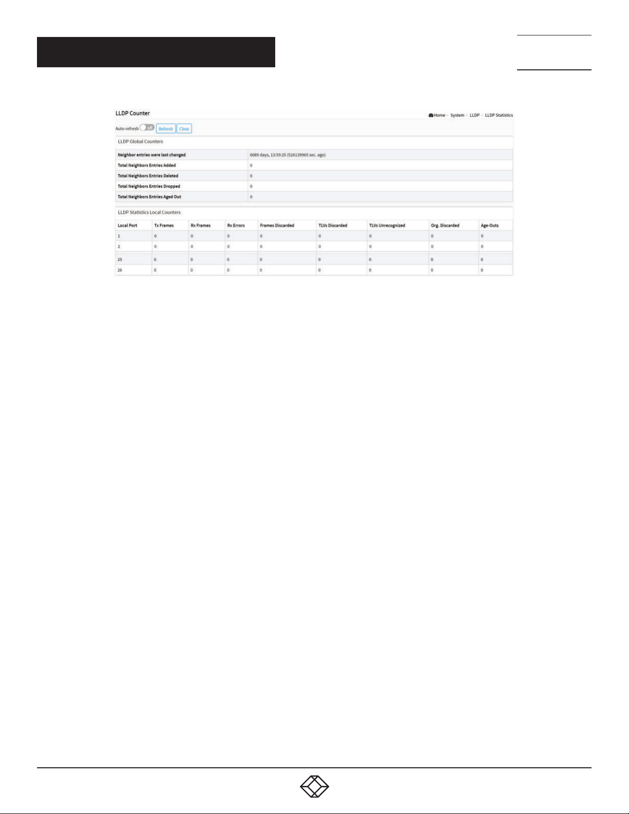
CHAPTER 3: SYSTEM
FIGURE 3-12. LLDP STATISTICS INFORMATION
NEED HELP?
LEAV E TH E TEC H TO US
LIVE 24/7
TECHNICAL
SUPPORT
1. 87 7.8 77. 22 69
Global Counters
Neighbor entries were last changed at: It also shows the time when the last entry was last deleted or added. It also shows the time
elapsed since the last change was detected.
Total Neighbors Entries Added: Shows the number of new entries added since switch reboot.
Total Neighbors Entries Deleted: Shows the number of new entries deleted since switch reboot.
Total Neighbors Entries Dropped: Shows the number of LLDP frames dropped due to the entry table being full.
Total Neighbors Entries Aged Out: Shows the number of entries deleted due to Time-To-Live expiring.
Local Counters
The displayed table contains a row for each port. The columns hold the following information:
Local Port: The port on which LLDP frames are received or transmitted.
Tx Frames: The number of LLDP frames transmitted on the port.
Rx Frames: The number of LLDP frames received on the port.
Rx Errors: The number of received LLDP frames containing some kind of error.
Frames Discarded: If an LLDP frame is received on a port, and the switch’s internal table has run full, the LLDP frame is counted and
discarded. This situation is known as “Too Many Neighbors” in the LLDP standard. LLDP frames require a new entry in the table when
the Chassis ID or Remote Port ID is not already contained within the table. Entries are removed from the table when a given port’s link
is down, an LLDP shutdown frame is received, or when the entry ages out.
TLVs Discarded: Each LLDP frame can contain multiple pieces of information, known as TLVs (TLV is short for “Type Length Value”). If
a TLV is malformed, it is counted and discarded.
TLVs Unrecognized: The number of well-formed TLVs, but with an unknown type value.
Org. Discarded: The number of organizationally received TLVs.
Age-Outs: Each LLDP frame contains information about how long the LLDP information is valid (age-out time). If no new LLDP frame
is received within the age out time, the LLDP information is removed, and the Age-Out counter is incremented.
Buttons
Auto-refresh: Check this box to refresh the page automatically. Automatic refresh occurs every 3 seconds.
Refresh: Click to refresh the page.
Clear: Clears the counters for the selected port.
1. 8 7 7. 8 7 7. 2 2 6 9 BL ACK BO X.COM
35
Page 36
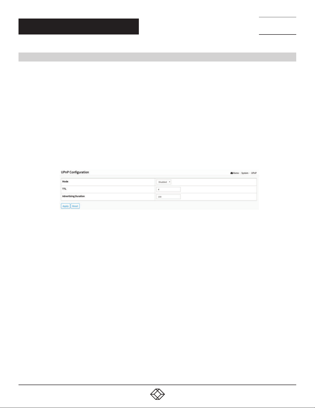
NEED HELP?
LEAV E TH E TEC H TO US
LIVE 24/7
CHAPTER 3: SYSTEM
TECHNICAL
SUPPORT
1. 87 7.8 77. 22 69
3.6 UPNP
UPnP is an acronym for Universal Plug and Play. The goals of UPnP are to allow devices to connect seamlessly and to simplify the
implementation of networks in the home (data sharing, communications, and entertainment) and in corporate environments for
simplified installation of computer components.
WEB INTERFACE
To configure the UPnP Configuration in the web interface:
1. Click System and UpnP.
2. Scroll to select the mode to enable or disable.
3. Specify the parameters in each blank field.
4. Click Apply to save the setting.
5. If you want to cancel the setting, then you need to click the Reset button.
6. It will revert to previously saved values.
FIGURE 3-13. UPNP CONFIGURATION SCREEN
PARAMETER DESCRIPTION
These parameters are displayed on the UPnP Configuration page:
Mode: Indicates the UPnP operation mode. Possible modes are:
Enabled: Enable UPnP mode operation.
Disabled: Disable UPnP mode operation.
Interface VLAN: Configure the interface VLAN that is used by UPnP. Allowed VLAN are in the range 1 through 4095, default being 1.
TTL: The TTL value is used by UPnP to send SSDP advertisement messages. Valid values are in the range 1 to 255.
Advertising Duration: The duration, carried in SSDP packets, is used to inform a control point or control points how often it or they
should receive an SSDP advertisement message from this switch. If a control point does not receive any message within the
duration, it will think that the switch no longer exists. Due to the unreliable nature of UDP, in the standard we recommend that such
refreshing of advertisements be done at less than one-half of the advertising duration. In the implementation, the switch sends
SSDP messages periodically at the interval one-half of the advertising duration minus 30 seconds. Valid values are in the range 100
to 86400.
Buttons
Apply: Click to save changes.
Reset: Click to undo any changes made locally and revert to previously saved values.
36
1. 8 7 7. 8 7 7. 2 2 6 9 BL ACK BO X.COM
Page 37
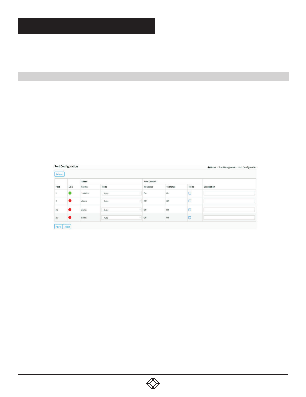
NEED HELP?
LEAV E TH E TEC H TO US
LIVE 24/7
CHAPTER 4: PORT MANAGEMENT
TECHNICAL
SUPPORT
1. 87 7.8 77. 22 69
This section describes how to configure the Port detail parameters of the switch. You can use the Port configure function to enable
or disable the Port of the switch and monitor the port’s content or status.
4.1 PORT CONFIGURATION
This page displays current port configurations. Ports can also be configured here.
WEB INTERFACE
To configure a Current Port Configuration in the web interface:
1. Click Port Management and Port Configuration.
2. Specify the Speed Configured, Flow Control.
3. Specify the detail Port alias or description an alphanumeric string describing the full name and version identification for the
system’s hardware type, software version, and networking application.
4. Click Apply.
FIGURE 4-1. PORT CONFIGURATION SCREEN
PARAMETER DESCRIPTION
Port: This is the logical port number for this row.
Link: The current link state is displayed graphically. Green indicates that the link is up and red that it is down.
Current Link Speed: Provides the current link speed of the port.
Configured Link Speed: Selects any available link speed for the given switch port. Only speeds supported by the specific port are
shown. Possible speeds are:
Disabled - Disables the switch port operation.
Auto - Port auto negotiates speed with the link partner and selects the highest speed that is compatible with the link partner.
10Mbps HDX - Forces the copper port in 10 Mbps half-duplex mode.
10Mbps FDX - Forces the copper port in 10 Mbps full duplex mode.
100Mbps HDX - Forces the copper port in 100 Mbps half-duplex mode.
100Mbps FDX - Forces the copper port in 100 Mbps full duplex mode.
1Gbps FDX - Forces the port in 1 Gbps full duplex mode.
2.5Gbps FDX - Forces the Serdes port in 2.5 Gbps full duplex mode.
1. 8 7 7. 8 7 7. 2 2 6 9 BL ACK BO X.COM
37
Page 38

NEED HELP?
LEAV E TH E TEC H TO US
LIVE 24/7
CHAPTER 4: PORT MANAGEMENT
SFP_Auto_ AMS - Automatically determines the speed of the SFP.
NOTE: There is no standardized way to do SFP auto detect, so here it is done by reading the SFP rom. Because there is no
standardized way of doing SFP auto detect, some SFPs might not be detectable. The port is set in AMS mode. The copper port is
set in Auto mode.
100-FX - SFP port in 100-FX speed. The copper port is disabled.
100-FX_AMS - Port in AMS mode. The SFP port is running at 100-FX speed. The copper port is n Auto mode.
1000-X - SFP port is running at 1000-X speed. The copper port is disabled.
1000-X_AMS - Port in AMS mode. SFP port is running at 1000-X speed. The copper port is in Auto mode. Ports in AMS mode with
1000-X speed have the copper port preferred. Ports in AMS mode with 100-FX speed have the fiber port preferred.
Flow Control: When Auto Speed is selected on a port, this section indicates the flow control capability that is advertised to the link
partner. When a fixed-speed setting is selected, that is what is used. The Current Rx column indicates whether pause frames on the
port are obeyed, and the Current Tx column indicates whether pause frames on the port are transmitted. The Rx and Tx settings are
determined by the result of the last Auto-Negotiation.
Check the configured column to use flow control. This setting is related to the setting for Configured Link Speed.
Description: Enter up to 63 characters to be the descriptive name that identifies this port.
Buttons
Refresh: Click to refresh the Port link Status manually.
Apply: Click to save changes.
Reset: Click to undo any changes made locally and revert to previously saved values.
TECHNICAL
SUPPORT
1. 87 7.8 77. 22 69
4.2 PORT STATISTICS
This section describes how to display the Port statistics information and provides an overview of general traffic statistics for all
switch ports.
WEB INTERFACE
To Display the Port Statistics Overview in the web interface:
1. Click Port Management and Port Statistics.
2. If you want to auto-refresh, then you need to evoke the “Auto-refresh”.
3. Click “ Refresh“ to refresh the port statistics or clear all information when you click “ Clear”.
4. If you want to see the details of the port statistics, then you need to click that port.
38
FIGURE 4-2. PORT STATISTICS OVERVIEW
1. 8 7 7. 8 7 7. 2 2 6 9 BL ACK BO X.COM
Page 39
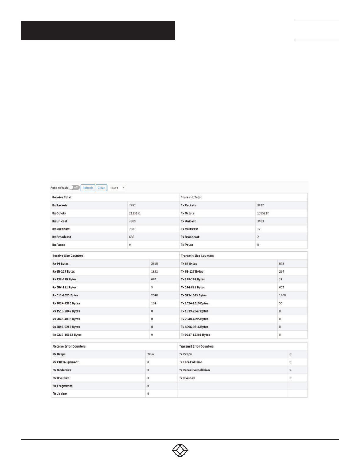
NEED HELP?
LEAV E TH E TEC H TO US
LIVE 24/7
CHAPTER 4: PORT MANAGEMENT
PARAMETER DESCRIPTION
Port: The logical port for the settings contained in the same row.
Packets: The number of received and transmitted packets per port.
Bytes: The number of received and transmitted bytes per port.
Errors: The number of frames received in error and the number of incomplete transmissions per port.
Drops: The number of frames discarded due to ingress or egress congestion.
Buttons
Auto-refresh: Check this box to refresh the page automatically. Automatic refresh occurs every 3 seconds.
Refresh: Click to refresh the page.
Clear: Clears the counters for all ports.
If you want to see the details of the port statistics, then you need to click that port. The displayed counters are the totals for receive
and transmit, the size counters for receive and transmit, and the error counters for receive and transmit.
TECHNICAL
SUPPORT
1. 87 7.8 77. 22 69
FIGURE 4-3. DETAILED PORT STATISTICS
1. 8 7 7. 8 7 7. 2 2 6 9 BL ACK BO X.COM
39
Page 40

NEED HELP?
LEAV E TH E TEC H TO US
LIVE 24/7
CHAPTER 4: PORT MANAGEMENT
PARAMETER DESCRIPTION
Upper left scroll bar: Scroll to the port to display the Port statistics with “Port-1”, “Port-2”, ...
Receive Total and Transmit Total
Rx and Tx Packets: The number of received and transmitted (good and bad) packets.
Rx and Tx Octets: The number of received and transmitted (good and bad) bytes. Includes FCS, but excludes framing bits.
Rx and Tx Unicast: The number of received and transmitted (good and bad) unicast packets.
Rx and Tx Multicast: The number of received and transmitted (good and bad) multicast packets.
Rx and Tx Broadcast: The number of received and transmitted (good and bad) broadcast packets.
Rx and Tx Pause: A count of the MAC Control frames received or transmitted on this port that have an opcode indicating a PAUSE
operation.
Receive and Transmit Size Counters
The number of received and transmitted (good and bad) packets split into categories based on their respective frame sizes.
Receive Error Counters
Rx Drops: The number of frames dropped due to lack of receive buffers or egress congestion.
Rx CRC/Alignment: The number of frames received with CRC or alignment errors.
Rx Undersize: The number of short 1 frames received with valid CRC.
Rx Oversize: The number of long 2 frames received with valid CRC.
Rx Fragments: The number of short 1 frames received with invalid CRC.
Rx Jabber: The number of long 2 frames received with invalid CRC.
Transmit Error Counters
Tx Drops: The number of frames dropped due to output buffer congestion.
Tx Late/Exc. Coll.: The number of frames dropped due to excessive or late collisions.
Tx Oversize: The number of frames dropped due to frame oversize.
Buttons
Auto-refresh: Check this box to refresh the page automatically. Automatic refresh occurs every 3 seconds.
Refresh: Click to refresh the page.
Clear: Clears the counters for the selected port.
TECHNICAL
SUPPORT
1. 87 7.8 77. 22 69
4.3 SFP PORT INFO
This section describes how the switch displays the SFP module detail information connected to the switch. The information
includes: Connector type, Fiber type, wavelength, bit rate and Vendor OUI etc.
WEB INTERFACE
To Display the SFP information in the web interface:
1. Click Port Management and SFP Port Info.
2. The SFP Information displays.
40
1. 8 7 7. 8 7 7. 2 2 6 9 BL ACK BO X.COM
Page 41

CHAPTER 4: PORT MANAGEMENT
FIGURE 4-4. SFP PORT INFORMATION SCREEN
NEED HELP?
LEAV E TH E TEC H TO US
LIVE 24/7
TECHNICAL
SUPPORT
1. 87 7.8 77. 22 69
PARAMETER DESCRIPTION
Upper left scroll bar: To scroll which port to display the Port statistics.
Connector Type: Displays the connector type, for instance, UTP, SC, ST, LC and so on.
Fiber Type: Displays the fiber mode, for instance, Multi-Mode, Single-Mode.
Tx Central Wavelength: Displays the fiber optical transmitting central wavelength, for instance, 850 nm, 1310 nm, 1550 nm, and so
on.
Bit Rate: Displays the nominal bit rate of the transceiver.
Vendor OUI: Displays the Manufacturer’s OUI code, which is assigned by IEEE.
Vendor Name: Displays the company name of the module manufacturer.
Vendor P/N: Displays the product name of the naming by module manufacturer.
Vendor Rev (Revision): Displays the module revision.
Vendor SN (Serial Number): Shows the serial number assigned by the manufacturer.
Date Code: Shows the date this SFP module was made.
Temperature: Shows the current temperature of the SFP module.
Vcc: Shows the working DC voltage of the SFP module.
Mon1(Bias) mA: Shows the Bias current of the SFP module.
Mon2(TX PWR): Shows the transmit power of the SFP module.
Mon3(RX PWR): Shows the receiver power of the SFP module.
Buttons
Auto-refresh: Check this box to refresh the page automatically. Automatic refresh occurs every 3 seconds.
Refresh: Click to refresh the page.
1. 8 7 7. 8 7 7. 2 2 6 9 BL ACK BO X.COM
41
Page 42
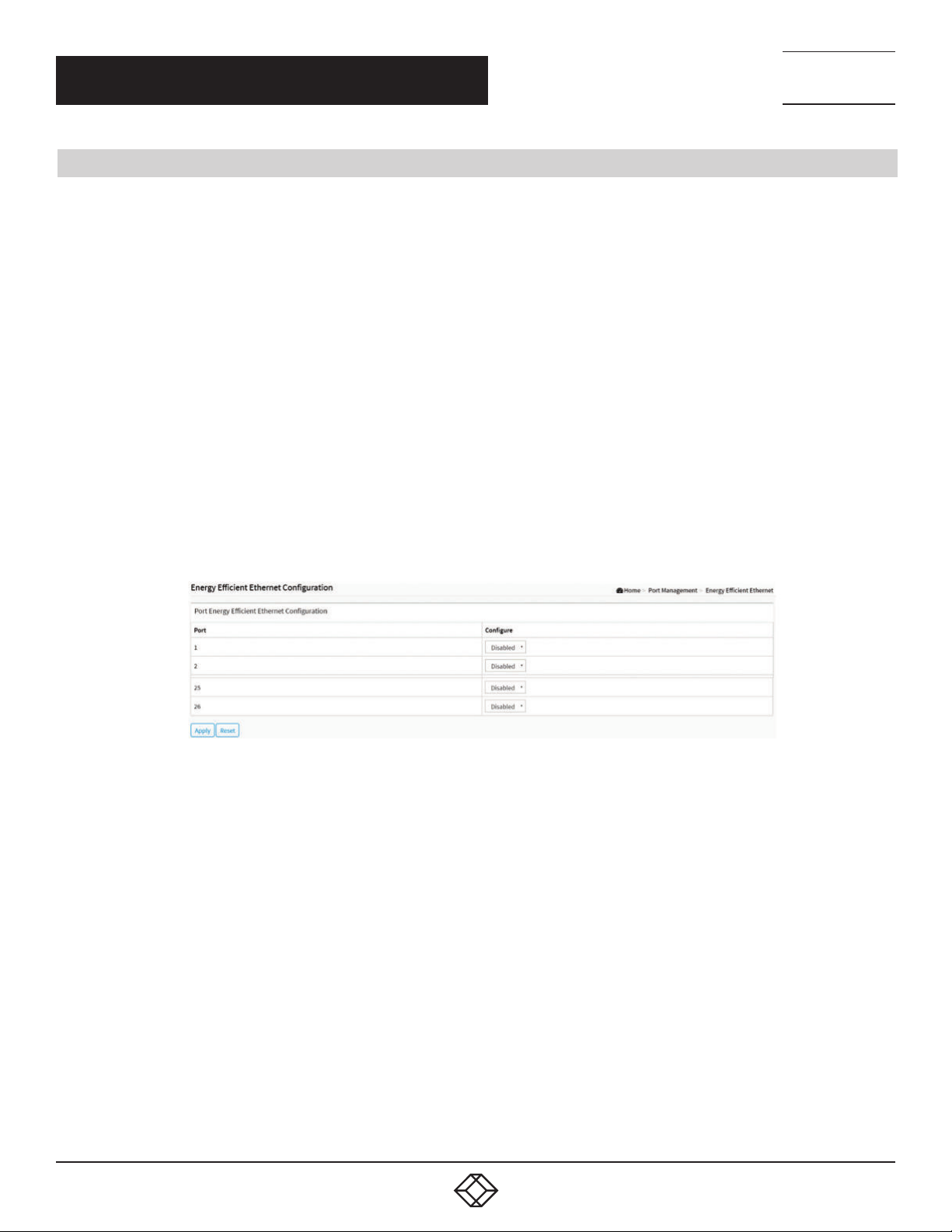
NEED HELP?
LEAV E TH E TEC H TO US
LIVE 24/7
CHAPTER 4: PORT MANAGEMENT
4.4 ENERGY EFFICIENT ETHERNET
EEE is an abbreviation for Energy Efficient Ethernet defined in IEEE 802.3az.
This page allows the user to inspect and configure the current EEE port settings.
EEE is a power saving option that reduces the power usage when there is very low traffic utilization (or no traffic).
EEE works by powering down circuits when there is no traffic. When a port gets data to be transmitted, all circuits are powered up.
The time it takes to power up the circuits is named wakeup time. The default wakeup time is 17 us for 1 Gbit links and 30 µs for
other link speeds. EEE devices must agree upon the value of the wakeup time to make sure that both the receiving and transmitting
device have all circuits powered up when traffic is transmitted. The devices can exchange information about the devices’ wakeup
time using the LLDP protocol.
WEB INTERFACE
To configure an Energy Efficient Ethernet in the web interface:
1. Click Port Management and Energy Efficient Ethernet.
2. Select enable or disable Energy Efficient Ethernet by the port.
3. Click apply to save the setting.
4. If you want to cancel the setting, then you need to click the Reset button. It will revert to previously saved values.
TECHNICAL
SUPPORT
1. 87 7.8 77. 22 69
PARAMETER DESCRIPTION
Port: The switch port number of the logical EEE port.
Configure: Controls whether EEE is enabled for this switch port.
Buttons
Apply: Click to save changes.
Reset: Click to undo any changes made locally and revert to previously saved values.
42
FIGURE 4-5. ENERGY EFFICIENT ETHERNET CONFIGURATION SCREEN
1. 8 7 7. 8 7 7. 2 2 6 9 BL ACK BO X.COM
Page 43
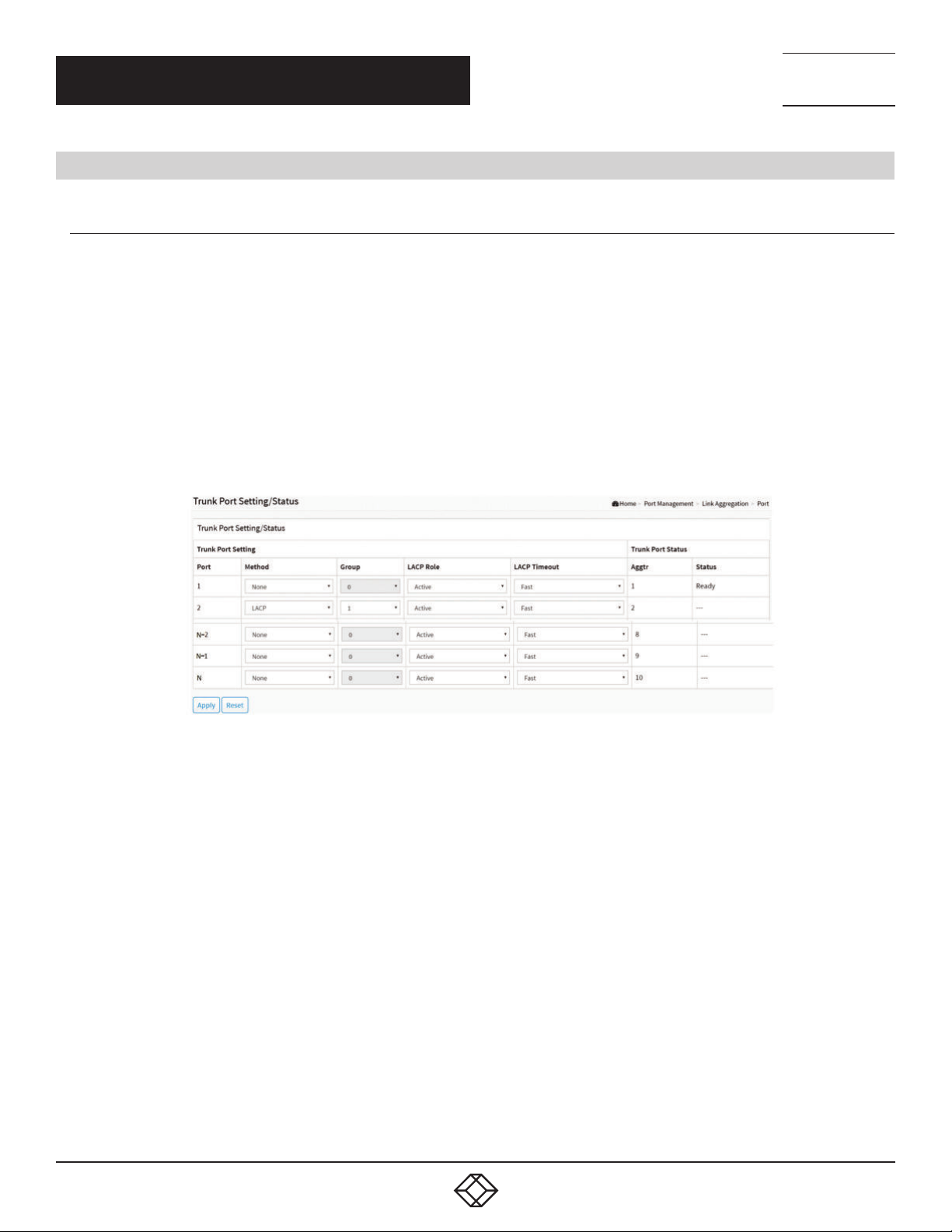
NEED HELP?
LEAV E TH E TEC H TO US
LIVE 24/7
CHAPTER 4: PORT MANAGEMENT
TECHNICAL
SUPPORT
1. 87 7.8 77. 22 69
4.5 LINK AGGREGATION
4.5.1 P O R T
This section describes the Port setting/status that is used to configure the trunk property of each and every port in the switch
system.
WEB INTERFACE
To configure the trunk property of each and every port in the web interface:
1. Click Port Management, Link Aggregation and port.
2. Specify the Method, Group, LACP Role and LACP Timeout.
3. Click apply to save the setting.
4. If you want to cancel the setting, then you need to click the Reset button. It will revert to previously saved values.
FIGURE 4-6. TRUNK PORT SETTING/STATUS
PARAMETER DESCRIPTION
Port: The logical port for the settings contained in the same row.
Method: This determines the method a port uses to aggregate with other ports.
- None: A port that does not want to aggregate with any other port should choose this default setting.
- LACP: A port uses LACP as its trunk method to get aggregated with other ports also using LACP.
- Static: A port uses Static Trunk as its trunk method to get aggregated with other ports also using Static Trunk.
Group: Ports choosing the same trunking method other than “None” must be assigned a unique Group number to declare that they
want to aggregate with each other.
LACP Role: This field is only referenced when a port’s trunking method is LACP.
- Active: An Active LACP port begins to send LACPDU to its link partner right after the LACP protocol entity started to take control of
this port.
- Passive: A Passive LACP port will not actively send LACPDU out before it receives an LACPDU from its link partner.
LACP Timeout: The Timeout controls the period between BPDU transmissions.
- Fast: It will transmit LACP packets each second.
- Slow: It will wait for 30 seconds before sending an LACP packet.
1. 8 7 7. 8 7 7. 2 2 6 9 BL ACK BO X.COM
43
Page 44
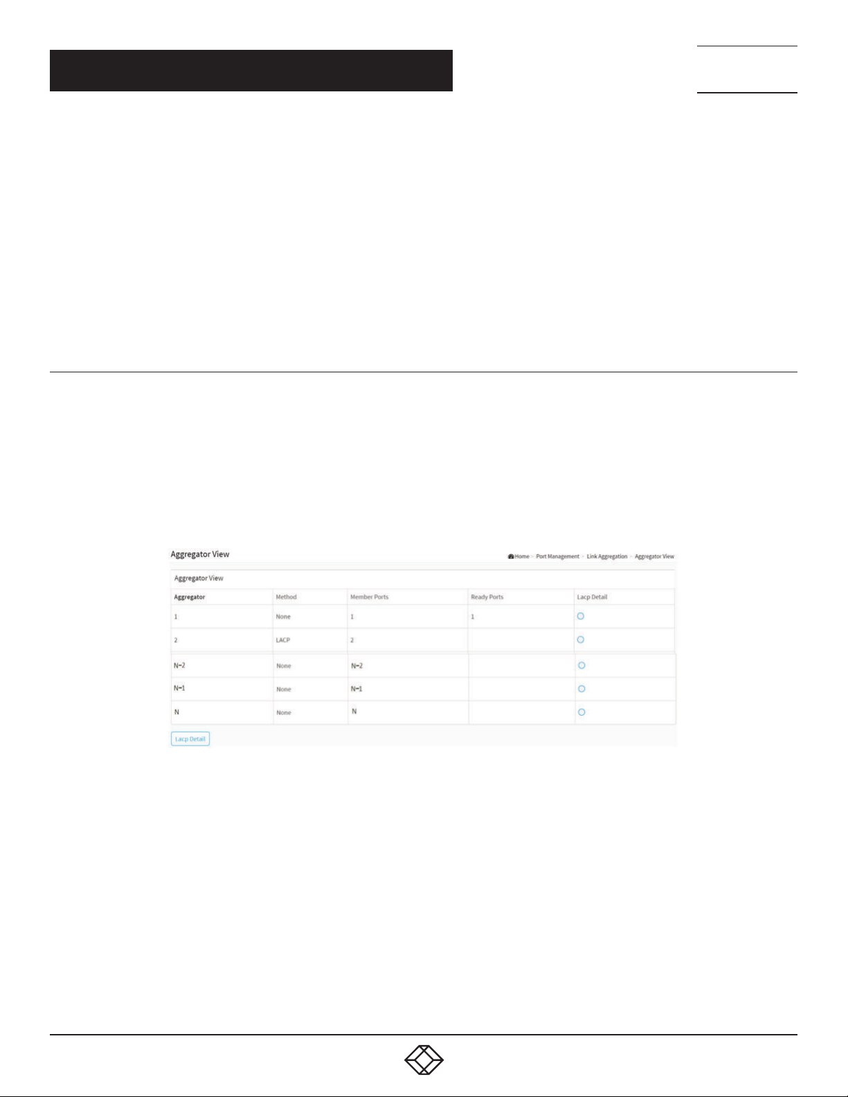
NEED HELP?
LEAV E TH E TEC H TO US
LIVE 24/7
CHAPTER 4: PORT MANAGEMENT
Aggtr: Aggtr is an abbreviation of “aggregator”. Every port is also an aggregator, and its own aggregator ID is the same as its own Port
No. We can regard an aggregator as a representative of a trunking group. Ports with same Group ID and using same trunking method
will have the opportunity to aggregate to a particular aggregator port. This aggregator port is usually the port with the smallest Port
No. within the trunking group.
Status: This field represents the trunking status of a port that uses a trunking method other than “None”. It also represents the
management link status of a port that uses the “None” trunking method. “---“ means “not ready”
Buttons
Apply: Click to save changes.
Reset: Click to undo any changes made locally and revert to previously saved values.
TECHNICAL
SUPPORT
1. 87 7.8 77. 22 69
4.5.2 AGGREGATOR VIEW
Display the current port trunking information from the aggregator point of view.
WEB INTERFACE
To see the LACP detail in the web interface:
1. Click Port Management, Link Aggregation and Aggregator View.
2. Click LACP Detail.
FIGURE 4-7. THE AGGREGATOR VIEW
PARAMETER DESCRIPTION
Aggregator: It shows the aggregator ID of every port. In fact, every port is also an aggregator, and its own aggregator ID is the same as
its own Port No.
Method: Shows the method a port uses to aggregate with other ports.
Member Ports: Shows all member ports of an aggregator (port).
Ready Ports: Shows only the ready member ports within an aggregator (port).
Lacp Detail: You can select the port that you want to see the LACP Detail.
Buttons
Lacp Detail: Click this button, then you will see the aggregator information. Details will be described in the next screen.
44
1. 8 7 7. 8 7 7. 2 2 6 9 BL ACK BO X.COM
Page 45
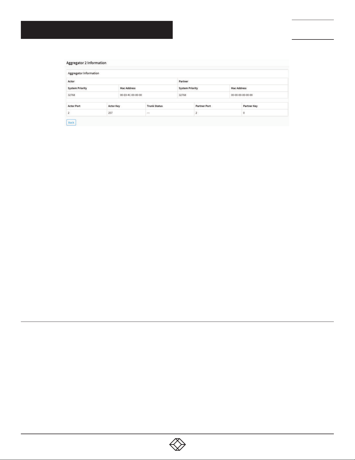
NEED HELP?
LEAV E TH E TEC H TO US
LIVE 24/7
CHAPTER 4: PORT MANAGEMENT
TECHNICAL
SUPPORT
1. 87 7.8 77. 22 69
FIGURE 4-8. THE LACP DETAIL
PARAMETER DESCRIPTION
Actor
System Priority: Shows the System Priority part of the aggregation Actor. (1-65535)
Mac Address: The system ID of the aggregation Actor.
Actor Port: The actor’s port number connected to this port.
Actor Key: The Key that the actor has assigned to this aggregation ID.
Partner
System Priority: Shows the System Priority part of the aggregation partner. (1-65535)
Mac Address: The system ID of the aggregation partner.
Partner Port: The partner’s port number connected to this port.
Partner Key: The Key that the partner has assigned to this aggregation ID.
Trunk Status: This field represents the trunking status of a port that uses a trunking method other than “None”. It also represents the
management link status of a port that uses the “None” trunking method. “---“ means “not ready”
Button
Back: Click to undo any changes made locally and return to the Users.
4.5.3 AGGREGATION HASH MODE
WEB INTERFACE
To configure the Aggregation hash mode in the web interface:
1. Click Port Management, Link Aggregation and Aggregator Hash Mode.
2. Click Hash Code Contributors to select the mode.
3. Click apply to save the setting.
4. If you want to cancel the setting, then you need to click the Reset button. It will revert to previously saved values.
1. 8 7 7. 8 7 7. 2 2 6 9 BL ACK BO X.COM
45
Page 46
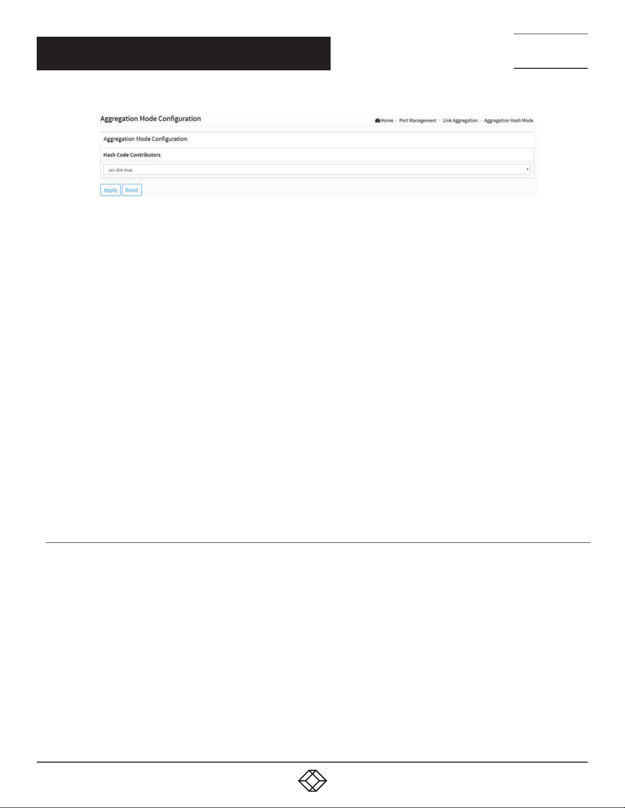
NEED HELP?
LEAV E TH E TEC H TO US
LIVE 24/7
CHAPTER 4: PORT MANAGEMENT
FIGURE 4-9.AGGREGATION HASH MODE
PARAMETER DESCRIPTION
Hash Code Contributors
src-mac: Source MAC Address
The Source MAC address can be used to calculate the destination port for the frame. Check to enable the use of the Source MAC
address, or uncheck to disable. By default, Source MAC Address is enabled.
dst-mac: Destination MAC Address: The Destination MAC Address can be used to calculate the destination port for the frame. Check
to enable the use of the Destination MAC Address, or uncheck to disable. By default, Destination MAC Address is disabled.
ip: IP Address: The IP address can be used to calculate the destination port for the frame. Check to enable the use of the IP Address,
or uncheck to disable. By default, IP Address is enabled.
src-dst-mac: Source MAC Address + Destination MAC Address.
src-ip: Source IP Address.
dst-ip: Destination IP Address.
src-dst-ip: Source IP Address + Destination IP Address.
Buttons
Apply: Click to save changes.
Reset: Click to undo any changes made locally and revert to previously saved values.
TECHNICAL
SUPPORT
1. 87 7.8 77. 22 69
4.5.4 LACP SYSTEM PRIORITY
It is used to set the priority part of the LACP system ID. LACP will only aggregate together the ports whose peer link partners are all
on a single system. Each system that supports LACP will be assigned a globally unique System Identifier for this purpose. A system
ID is a 64-bit field comprising a 48-bit MAC Address and 16-bit priority value. The System Priority can be set by the user. Its range is
from 1 to 65535. Default: 32768
WEB INTERFACE
To configure the LACP System Priority in the web interface:
1. Click Port Management, Link Aggregation and LACP System Priority.
2. Specify the LACP System Priority.
3. Click apply to save the setting.
4. If you want to cancel the setting, then you need to click the Reset button. It will revert to previously saved values.
46
1. 8 7 7. 8 7 7. 2 2 6 9 BL ACK BO X.COM
Page 47
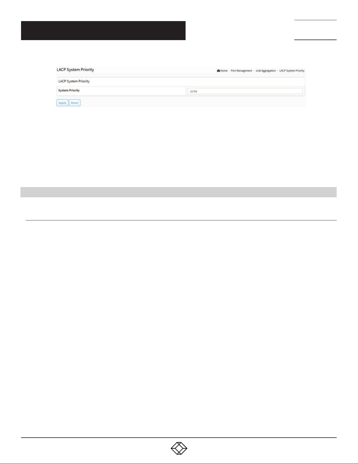
CHAPTER 4: PORT MANAGEMENT
FIGURE 4-10.LACP SYSTEM PRIORITY
PARAMETER DESCRIPTION
System Priority: 1-65535. Show the System Priority part of a system ID.
Buttons
Apply: Click to save changes.
Reset: Click to undo any changes made locally and revert to previously saved values.
NEED HELP?
LEAV E TH E TEC H TO US
LIVE 24/7
TECHNICAL
SUPPORT
1. 87 7.8 77. 22 69
4.6 LOOP PROTECTION
4.6.1 CONFIGURATION
The loop Protection is used to detect the presence of traffic. When the switch receives a packet’s (looping detection frame) MAC
address the same as oneself from a port, Loop Protection occurs. The port will be locked when it receives the looping Protection
frames. If you want to resume the locked port, find out the looping path and remove the looping path, then click on “Resume” to turn
on the locked ports.
WEB INTERFACE
To configure the Loop Protection parameters in the web interface:
1. Click Port Management, Loop Protection and Configuration.
2. Select enable or disable the port loop Protection.
3. Click apply to save the setting.
4. If you want to cancel the setting, then you need to click the Reset button. It will revert to previously saved values.
1. 8 7 7. 8 7 7. 2 2 6 9 BL ACK BO X.COM
47
Page 48
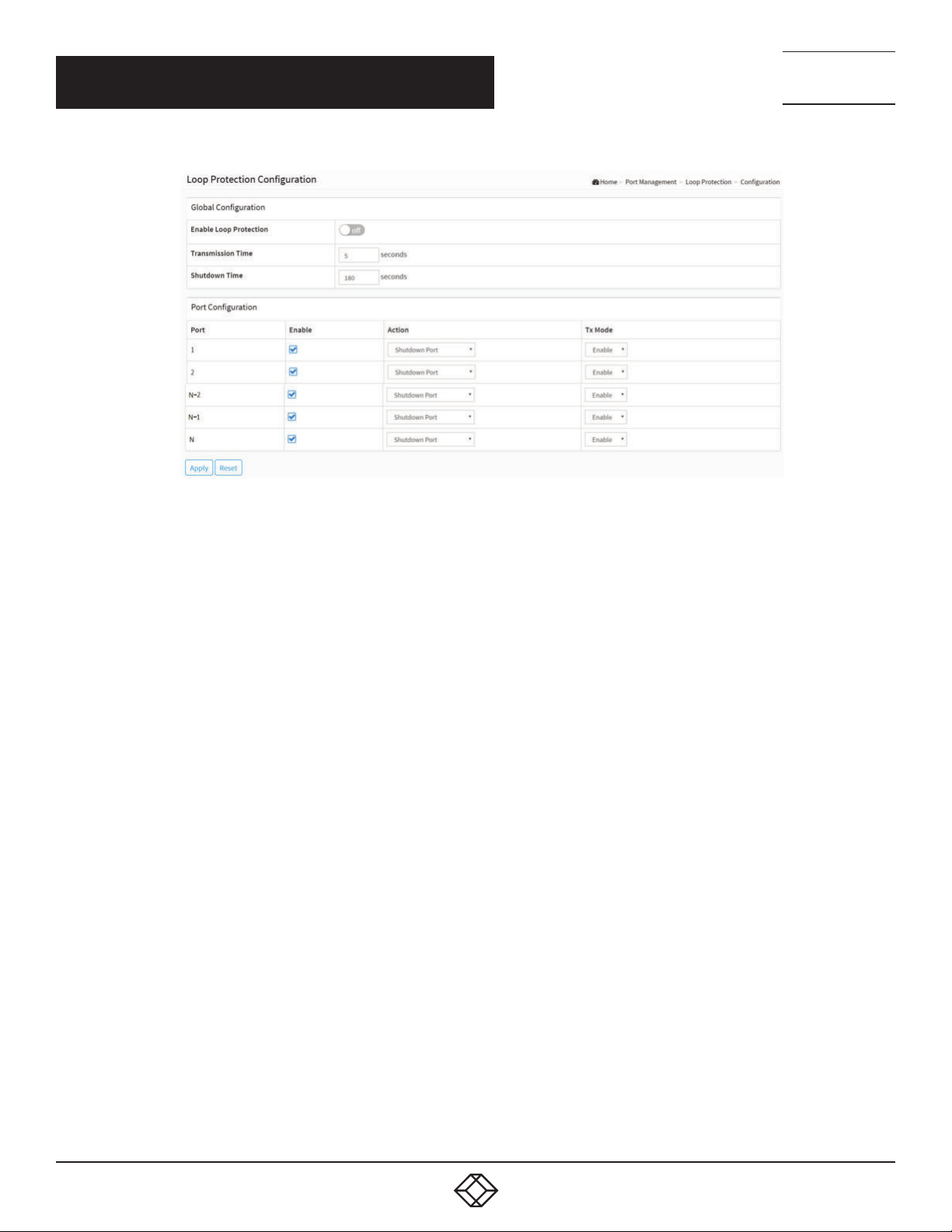
CHAPTER 4: PORT MANAGEMENT
NEED HELP?
LEAV E TH E TEC H TO US
LIVE 24/7
TECHNICAL
SUPPORT
1. 87 7.8 77. 22 69
FIGURE 4-11. LOOP PROTECTION CONFIGURATION SCREEN
PARAMETER DESCRIPTION
Global Configuration
Enable Loop Protection: Controls whether loop protections is enabled (as a whole).
Transmission Time: The interval between each loop protection PDU sent on each port. Valid values are 1 to 10 seconds.
Shutdown Time: The period (in seconds) for which a port will be kept disabled if a loop is detected (and the port action shuts down
the port). Valid values are 10 to 604800 seconds (7 days).
Port Configuration
Port: The switch port number of the port.
Enable: Controls whether loop protection is enabled on this switch port.
Action: Configures the action performed when a loop is detected on a port. Valid values are Shutdown Port, Shutdown Port and Log
or Log Only.
Tx Mode: Controls whether the port is actively generating loop protection PDU’s, or whether it is just passively looking for looped
PDU’s.
Buttons
Apply: Click to save changes.
Reset: Click to undo any changes made locally and revert to previously saved values.
48
1. 8 7 7. 8 7 7. 2 2 6 9 BL ACK BO X.COM
Page 49
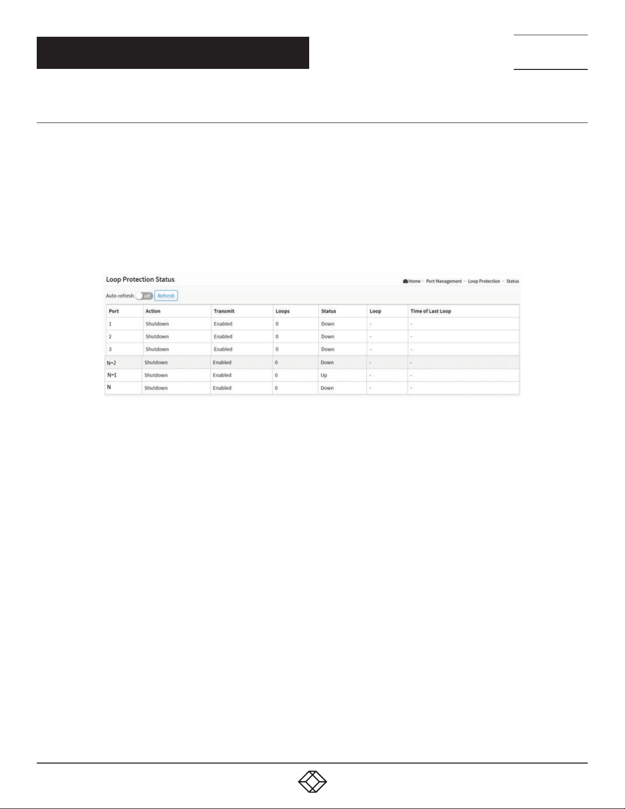
CHAPTER 4: PORT MANAGEMENT
4.6.2 STATUS
This section displays the loop protection port status for the ports of the currently selected switch.
WEB INTERFACE
To display the Loop Protection status in the web interface:
1. Click Port Management, Loop Protection and Status.
2. If you want to auto-refresh the information, then you need to select “Auto refresh”.
3. Click “Refresh” to refresh the Loop Protection Status.
NEED HELP?
LEAV E TH E TEC H TO US
LIVE 24/7
TECHNICAL
SUPPORT
1. 87 7.8 77. 22 69
FIGURE 4-12. LOOP PROTECTION STATUS SCREEN
PARAMETER DESCRIPTION
Parameter description:
Port: The switch port number of the logical port.
Action: The currently configured port action.
Transmit: The currently configured port transmit mode.
Loops: The number of loops detected on this port.
Status: The current loop protection status of the port.
Loop: Whether a loop is currently detected on the port.
Time of Last Loop: The time of the last loop event detected.
Buttons
Auto-refresh: Check this box to refresh the page automatically. Automatic refresh occurs every 3 seconds.
Refresh: Click to refresh the page immediately.
1. 8 7 7. 8 7 7. 2 2 6 9 BL ACK BO X.COM
49
Page 50
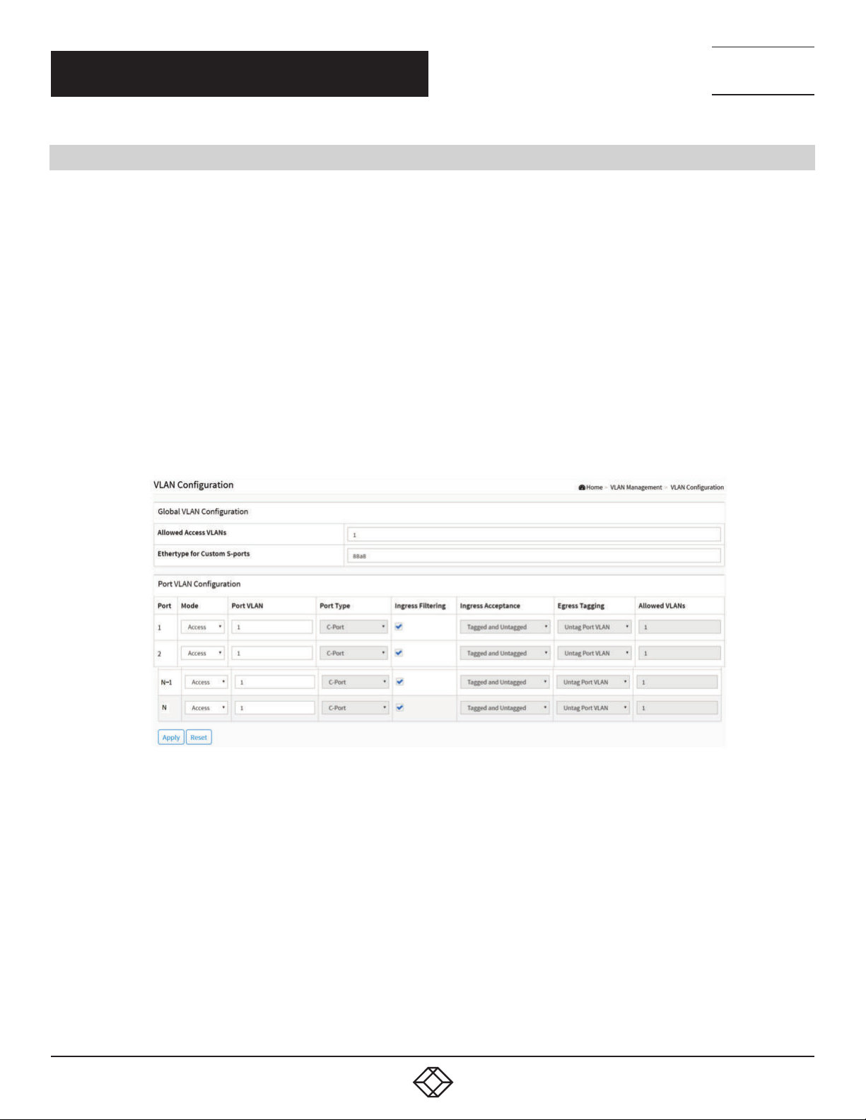
NEED HELP?
LEAV E TH E TEC H TO US
LIVE 24/7
CHAPTER 5: VLAN MANAGEMENT
5.1 VLAN CONFIGUR ATION
This section explains how to assign a specific VLAN for management purposes. The management VLAN is used to establish an IP
connection to the switch from a workstation connected to a port in the VLAN. This connection supports a VSM, SNMP, and Telnet
session. By default, the active management VLAN is VLAN 1, but you can designate any VLAN as the management VLAN using the
Management VLAN window. Only one management VLAN can be active at a time.
When you specify a new management VLAN, your HTTP connection to the old management VLAN is lost. For this reason, you
should have a connection between your management station and a port in the new management VLAN or connect to the new
management VLAN through a multi-VLAN route.
WEB INTERFACE
To configure VLAN membership in the web interface:
1. Click VLAN Management and VLAN Configuration.
2. Specify Existing VLANs, Ether type for Custom S-ports.
3. Click Apply.
TECHNICAL
SUPPORT
1. 87 7.8 77. 22 69
PARAMETER DESCRIPTION
Global VLAN Configuration
Allowed Access VLANs: This field shows the VLANs that are created on the switch.
By default, only VLAN 1 exists. More VLANs may be created by using a list syntax where the individual elements are separated by
commas. Ranges are specified with a dash separating the lower and upper bound.
The following example will create VLANs 1, 10, 11, 12, 13, 200, and 300: 1, 10-13, 200, 300. Spaces are allowed in between the
delimiters.
Ethertype for Custom S-ports: This field specifies the ethertype/TPID (specified in hexadecimal) used for Custom S-ports. The
setting is in force for all ports whose Port Type is set to S-Custom-Port.
50
FIGURE 5-1. VLAN CONFIGURATION SCREEN
1. 8 7 7. 8 7 7. 2 2 6 9 BL ACK BO X.COM
Page 51

NEED HELP?
LEAV E TH E TEC H TO US
LIVE 24/7
CHAPTER 5: VLAN MANAGEMENT
TECHNICAL
SUPPORT
1. 87 7.8 77. 22 69
Port VLAN Configuration
Port: This is the logical port number of this row.
Mode: The port mode (default is Access) determines the fundamental behavior of the port in question. A port can be in one of three
modes as described below.
Whenever a particular mode is selected, the remaining fields in that row will be either grayed out or made changeable depending on
the mode in question.
Grayed out fields show the value that the port will get when the mode is applied.
Access:
Access ports are normally used to connect to end stations. Dynamic features like Voice VLAN may add the port to more VLANs behind
the scenes. Access ports have the following characteristics:
- Member of exactly one VLAN, the Port VLAN (a.k.a. Access VLAN), which by default is 1,
- accepts untagged frames and C-tagged frames,
- discards all frames that are not classified to the Access VLAN,
- on egress all frames are transmitted untagged.
Trunk:
Trunk ports can carry traffic on multiple VLANs simultaneously, and are normally used to connect to other switches. Trunk ports have
the following characteristics:
- By default, a trunk port is member of all existing VLANs. This may be limited by the use of Allowed VLANs,
- unless VLAN Trunking is enabled on the port, frames classified to a VLAN that the port is not a member of will be discarded,
- by default, all frames but frames classified to the Port VLAN (a.k.a. Native VLAN) get tagged on egress. Frames classified to the Port
VLAN do not get C-tagged on egress,
- egress tagging can be changed to tag all frames, in which case only tagged frames are accepted on ingress,
- VLAN trunking may be enabled.
Hybrid:
Hybrid ports resemble trunk ports in many ways, but add additional port configuration features. In addition to the characteristics
described for trunk ports, hybrid ports have these abilities:
- Can be configured to be VLAN tag unaware, C-tag aware, S-tag aware, or S-custom-tag aware,
- ingress filtering can be controlled,
- ingress acceptance of frames and configuration of egress tagging can be configured independently.
Port VLAN: Determines the port’s VLAN ID (a.k.a. PVID). Allowed VLANs are in the range 1 through 4095, default being 1.
On ingress, frames get classified to the Port VLAN if the port is configured as VLAN unaware, the frame is untagged, or VLAN
awareness is enabled on the port, but the frame is priority tagged (VLAN ID = 0).
On egress, frames classified to the Port VLAN do not get tagged if Egress Tagging configuration is set to untag Port VLAN.
The Port VLAN is called an “Access VLAN” for ports in Access mode and Native VLAN for ports in Trunk or Hybrid mode.
Port Type: Ports in hybrid mode allow for changing the port type, that is, whether a frame’s VLAN tag is used to classify the frame on
ingress to a particular VLAN, and if so, which TPID it reacts on. Likewise, on egress, the Port Type determines the TPID of the tag, if a
tag is required.
1. 8 7 7. 8 7 7. 2 2 6 9 BL ACK BO X.COM
51
Page 52

NEED HELP?
LEAV E TH E TEC H TO US
LIVE 24/7
CHAPTER 5: VLAN MANAGEMENT
Unaware:
On ingress, all frames, whether carrying a VLAN tag or not, get classified to the Port VLAN, and possible tags are not removed on
egress.
C-Port:
On ingress, frames with a VLAN tag with TPID = 0x8100 get classified to the VLAN ID embedded in the tag. If a frame is untagged or
priority tagged, the frame gets classified to the Port VLAN. If frames must be tagged on egress, they will be tagged with a C-tag.
S-Port:
On ingress, frames with a VLAN tag with TPID = 0x8100 or 0x88A8 get classified to the VLAN ID embedded in the tag. If a frame is
untagged or priority tagged, the frame gets classified to the Port VLAN. If frames must be tagged on egress, they will be tagged with
an S-tag.
S-Custom-Port:
On ingress, frames with a VLAN tag with a TPID = 0x8100 or equal to the Ethertype configured for Custom-S ports get classified to the
VLAN ID embedded in the tag. If a frame is untagged or priority tagged, the frame gets classified to the Port VLAN. If frames must be
tagged on egress, they will be tagged with the custom S-tag.
Ingress Filtering: Hybrid ports allow for changing ingress filtering. Access and Trunk ports always have ingress filtering enabled.
If ingress filtering is enabled (checkbox is checked), frames classified to a VLAN that the port is not a member of get discarded.
If ingress filtering is disabled, frames classified to a VLAN that the port is not a member of are accepted and forwarded to the switch
engine. However, the port will never transmit frames classified to VLANs that it is not a member of.
VLAN Trunking: Trunk and Hybrid ports allow for enabling VLAN trunking.
When VLAN trunking is enabled, frames classified to unknown VLANs are accepted on the port whether ingress filtering is enabled or
not.
This is useful in scenarios where a cloud of intermediary switches must bridge VLANs that haven’t been created. By configuring the
ports that connect the cloud of switches as trunking ports, they can seamlessly carry those VLANs from one end to the other.
Ingress Acceptance: Hybrid ports allow for changing the type of frames that are accepted on ingress.
Tagged and untagged
Both tagged and untagged frames are accepted.
Tagged Only
Only tagged frames are accepted on ingress. Untagged frames are discarded.
Untagged Only
Only untagged frames are accepted on ingress. Tagged frames are discarded.
Egress Tagging: Ports in Trunk and Hybrid mode may control the tagging of frames on egress.
Untag Port VLAN
Frames classified to the Port VLAN are transmitted untagged. Other frames are transmitted with the relevant tag.
Tag A ll
All frames, whether classified to the Port VLAN or not, are transmitted with a tag.
Untag All
All frames, whether classified to the Port VLAN or not, are transmitted without a tag.
This option is only available for ports in Hybrid mode.
TECHNICAL
SUPPORT
1. 87 7.8 77. 22 69
52
1. 8 7 7. 8 7 7. 2 2 6 9 BL ACK BO X.COM
Page 53
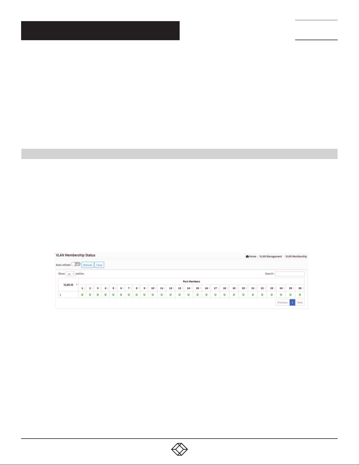
NEED HELP?
LEAV E TH E TEC H TO US
LIVE 24/7
CHAPTER 5: VLAN MANAGEMENT
Allowed VLANs: Ports in Trunk and Hybrid mode may control which VLANs they are allowed to become members of. Access ports
can only be member of one VLAN, the Access VLAN.
The field’s syntax is identical to the syntax used in the Existing VLANs field. By default, a port may become a member of all possible
VLANs, and is therefore set to 1-4095.
The field may be left empty, which means that the port will not be member of any of the existing VLANs, but if it is configured for
VLAN Trunking it will still be able to carry all unknown VLANs.
Buttons
Apply: Click to save changes.
Reset: Click to undo any changes made locally and revert to previously saved values.
5.2 VLAN MEMBERSHIP
This page provides an overview of membership status of VLAN users.
The ports belong to the currently selected stack unit, as reflected by the page header.
TECHNICAL
SUPPORT
1. 87 7.8 77. 22 69
WEB INTERFACE
To configure VLAN membership configuration in the web interface:
1. Click VLAN Management and VLAN membership.
2. Scroll to choose which VLANs you want to show.
3. Click Refresh to update the state.
FIGURE 5-2. VLAN MEMBERSHIP SCREEN
PARAMETER DESCRIPTION
VLAN USER: Various internal software modules may use VLAN services to configure VLAN memberships on the fly. The drop-
down list on the right allows for selecting between showing VLAN memberships as configured by an administrator (Admin) or as
configured by one of these internal software modules.
The “Combined” entry will show a combination of the administrator and internal software modules configuration, and basically
reflects what is actually configured in hardware.
VLAN User module uses services of the VLAN management functionality to configure VLAN memberships and VLAN port
configurations such as PVID and UVID. Currently, we support the following VLAN user types:
- NAS: NAS provides port-based authentication, which involves communications between a Supplicant, Authenticator, and an
Authentication Server.
1. 8 7 7. 8 7 7. 2 2 6 9 BL ACK BO X.COM
53
Page 54

NEED HELP?
LEAV E TH E TEC H TO US
LIVE 24/7
CHAPTER 5: VLAN MANAGEMENT
- GVRP: Adjacent VLAN-aware devices can exchange VLAN information with each other by using Generic VLAN Registration
Protocol (GVRP). GVRP is based on the Generic Attribute Registration Protocol (GARP) and propagates VLAN information
throughout a bridged network.
- MVR: MVR is used to eliminate the need to duplicate multicast traffic for subscribers in each VLAN. Multicast traffic for all
channels is sent only on a single (multicast) VLAN.
- Voice VLAN: Voice VLAN is a VLAN configured specially for voice traffic typically originating from IP phones.
- MSTP: The 802.1s Multiple Spanning Tree protocol (MSTP) uses VLANs to create multiple spanning trees in a network, which
significantly improves network resource use while maintaining a loop-free environment.
- DMS: Shows DMS VLAN membership status.
- VCL: Shows MAC-based VLAN entries configured by various MAC-based VLAN users.
VLAN ID: VLAN ID for which the Port members are displayed.
Port Members: A row of check boxes for each port is displayed for each VLAN ID.
If a port is included in a VLAN, an image and will be displayed. It shows egress filtering frame status whether tagged or untagged.
Frames classified to the Port VLAN are transmitted tagged( ) or untagged( ).
VLAN Membership: The VLAN Membership Status Page will show the current VLAN port members for all VLANs configured by a
selected VLAN User (selection shall be allowed by a Combo Box). When combined Users are selected, it will show this information
for all the VLAN Users, and this is by default. VLAN membership allows the frames classified to the VLAN ID to be forwarded on the
respective VLAN member ports.
Show entries: You can choose how many items you want to show up.
Admin drop-down box: You can choose the Vlan User.
Search: You can search for the information that you want to see.
Buttons
Auto-refresh: Check this box to refresh the page automatically. Automatic refresh occurs every 3 seconds.
Refresh: Click to refresh the page.
Clear: Click to clear the page.
Next: Updates the system log entries, turns to the next page.
Previous: Updates the system log entries, turns to the previous page.
TECHNICAL
SUPPORT
1. 87 7.8 77. 22 69
5.3 VLAN PORT STATUS
The Port Status function gathers the information of all VLAN status and reports it in order: Combined, Admin, NAS, GVRP, MVR,
Voice VLAN, MSTP, DMS, VCL.
WEB INTERFACE
To Display VLAN Port Status in the web interface:
1. Click VLAN Management and VLAN Port Status.
2. Specify the Combined, Admin, NAS, GVRP, MVR, Voice VLAN, MSTP, DMS, VCL.
3. Display Port Status information.
54
1. 8 7 7. 8 7 7. 2 2 6 9 BL ACK BO X.COM
Page 55
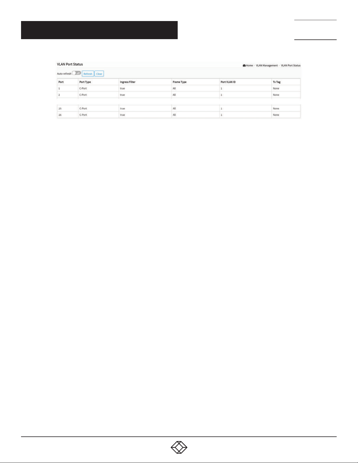
NEED HELP?
LEAV E TH E TEC H TO US
LIVE 24/7
CHAPTER 5: VLAN MANAGEMENT
TECHNICAL
SUPPORT
1. 87 7.8 77. 22 69
FIGURE 5-3. VLAN PORT STATUS SCREEN
PARAMETER DESCRIPTION
VLAN USER: The VLAN User module uses services of the VLAN management functionality to configure VLAN memberships and
VLAN port configuration such as PVID, UVID. The switch supports the following VLAN User types:
- NAS: NAS provides port-based authentication, which involves communications between a Supplicant, Authenticator, and an
Authentication Server.
- GVRP: Adjacent VLAN-aware devices can exchange VLAN information with each other by using Generic VLAN Registration Protocol
(GVRP). GVRP is based on the Generic Attribute Registration Protocol (GARP) and propagates VLAN information throughout a
bridged network.
- MVR: MVR is used to eliminate the need to duplicate multicast traffic for subscribers in each VLAN. Multicast traffic for all channels
is sent only on a single (multicast) VLAN.
- Voice VLAN: Voice VLAN is a VLAN configured specially for voice traffic typically originating from IP phones.
- MSTP: The 802.1s Multiple Spanning Tree protocol (MSTP) uses VLANs to create multiple spanning trees in a network, which
significantly improves network resource use while maintaining a loop-free environment.
- DMS: Shows DMS VLAN membership status.
- VCL: Shows MAC-based VLAN entries configured by various MAC-based VLAN users.
Port: The logical port for the settings contained in the same row.
Port Type: Shows the Port Type. Port type can be Unaware, C-port, S-port, Custom S-port.
If Port Type is Unaware, all frames are classified to the Port VLAN ID and tags are not removed. C-port is Customer Port. S-port is
Service port. Custom S-port is S-port with Custom TPID.
Ingress Filtering: Shows the ingress filtering on a port. This parameter affects VLAN ingress processing. If ingress filtering is enabled
and the ingress port is not a member of the classified VLAN, the frame is discarded.
Frame Type: Shows whether the port accepts all frames or only tagged frames. This parameter affects VLAN ingress processing. If
the port only accepts tagged frames, untagged frames received on that port are discarded.
Port VLAN ID: Shows the Port VLAN ID (PVID) that a given user wants the port to have. The field is empty if not overridden by the
selected user.
Tx Tag: Shows egress filtering frame status whether tagged or untagged.
Admin drop-down box: You can choose the Vlan User.
Buttons
Auto-refresh: Check this box to refresh the page automatically. Automatic refresh occurs every 3 seconds.
Refresh: Click to refresh the page.
Clear: Click to clear the page.
1. 8 7 7. 8 7 7. 2 2 6 9 BL ACK BO X.COM
55
Page 56
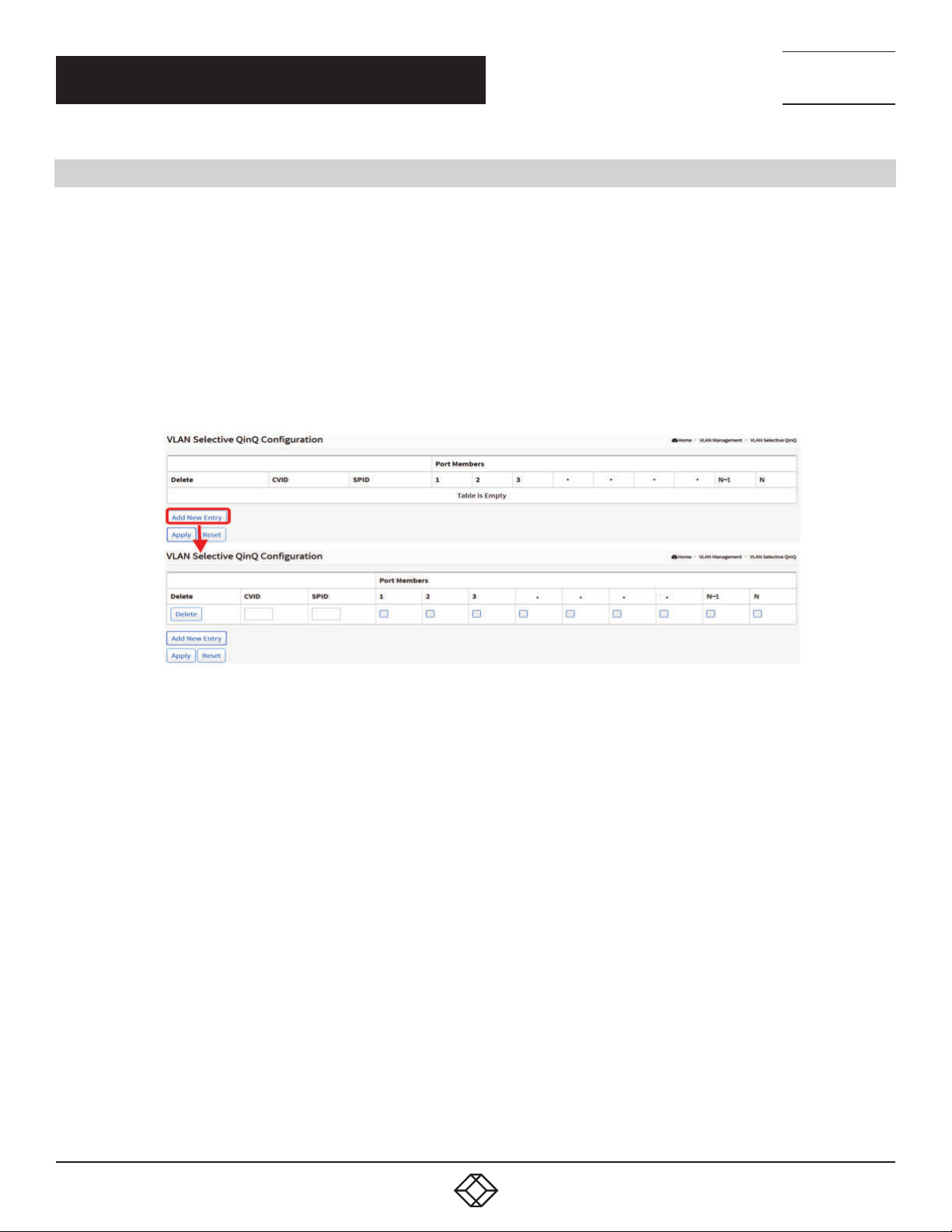
NEED HELP?
LEAV E TH E TEC H TO US
LIVE 24/7
CHAPTER 5: VLAN MANAGEMENT
5.4 VLAN SELECTIVE QINQ CONFIGURATION
A Q-in-Q VLAN tunnel enables a service provider to segregate the traffic of different customers in their infrastructure, while still
giving the customer a full range of VLANs for their internal use by adding a second 802.1Q tag to an already tagged frame.
WEB INTERFACE
To configure VLAN selective QinQ in the web interface:
1. Click VLAN Management and VLAN Selective QinQ Configuration.
2. Click “Add New Entry”.
3. Specify CVID, SPID, Port Members.
4. Click Apply.
TECHNICAL
SUPPORT
1. 87 7.8 77. 22 69
FIGURE 5-4. VLAN SELECTIVE QINQ SCREEN
PARAMETER DESCRIPTION
CVID: 1-4095, The customer VLAN ID List to which the tagged packets will be added.
SPID: 1-4095, This configures the VLAN to join the Service Providers VLAN as a tagged member.
Port Members: Checkmarks indicate which ports are members of the entry. Check or uncheck as needed to modify the entry.
Buttons
Delete: To delete a QinQ configuration entry, check this box. The entry will be deleted during the next Save.
Add New Entry: Click to add a new QinQ configuration.
Apply: Click to save changes.
Reset: Click to undo any changes made locally and revert to previously saved values.
56
1. 8 7 7. 8 7 7. 2 2 6 9 BL ACK BO X.COM
Page 57
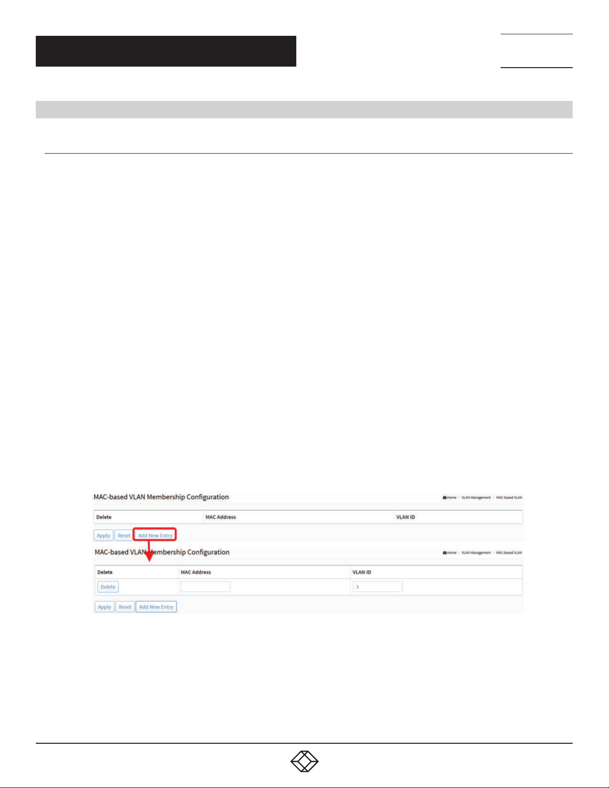
NEED HELP?
LEAV E TH E TEC H TO US
LIVE 24/7
CHAPTER 5: VLAN MANAGEMENT
TECHNICAL
SUPPORT
1. 87 7.8 77. 22 69
5.5 MAC-BASED VLAN
5.5.1 CONFIGURATION
MAC address-based VLAN decides the VLAN for forwarding an untagged frame based on the source MAC address of the frame.
The most common way of grouping VLAN members is by port, hence the name port-based VLAN. Typically, the device adds the
same VLAN tag to untagged packets that are received through the same port. Later on, these packets can be forwarded in the
same VLAN. Port-based VLAN is easy to configure, and applies to networks where the locations of terminal devices are relatively
fixed. As mobile office and wireless network access gain more popularity, the ports that terminal devices use to access the
networks are very often non-fixed. A device may access a network through Port A this time, but through Port B the next time. If Port
A and Port B belong to different VLANs, the device will be assigned to a different VLAN the next time it accesses the network. As
a result, it will not be able to use the resources in the old VLAN. On the other hand, if Port A and Port B belong to the same VLAN,
after terminal devices access the network through Port B, they will have access to the same resources as those accessing the
network through Port A do, which brings security issues. To provide user access and ensure data security in the meantime, the
MAC-based VLAN technology is used.
MAC-based VLANs group VLAN members by MAC address. With MAC-based VLAN configured, the device adds a VLAN tag
to an untagged frame according to its source MAC address. MAC-based VLANs are mostly used in conjunction with security
technologies such as 802.1X to provide secure, flexible network access for terminal devices.
WEB INTERFACE
To configure MAC address-based VLAN configuration in the web interface:
1. Click VLAN Management, MAC-based VLAN and Configuration.
2. Click “Add New Entry”.
3. Specify the MAC address and VLAN ID.
4. Click Apply.
FIGURE 5-5. MAC-BASED VLAN CONFIGURATION SCREEN
PARAMETER DESCRIPTION
MAC Address: Indicates the MAC address.
VLAN ID: Indicates the VLAN ID.
1. 8 7 7. 8 7 7. 2 2 6 9 BL ACK BO X.COM
57
Page 58
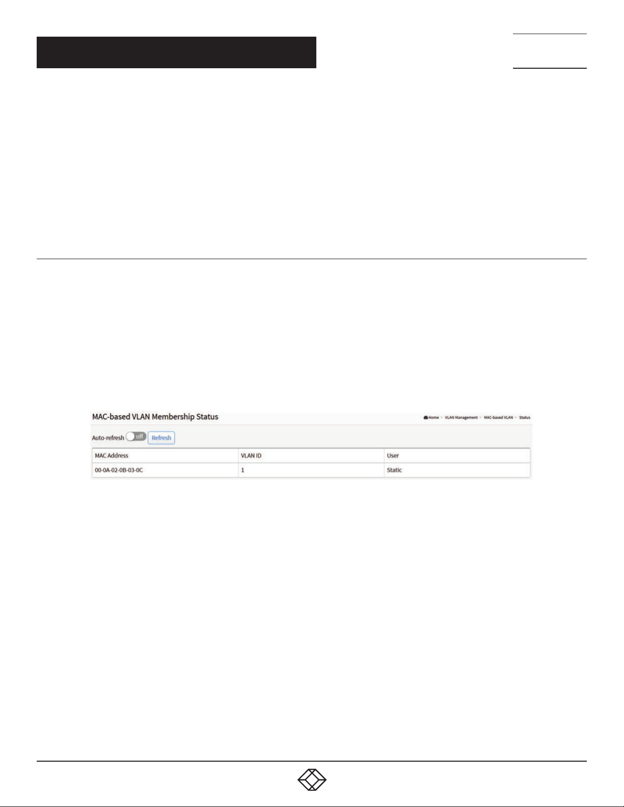
NEED HELP?
LEAV E TH E TEC H TO US
LIVE 24/7
CHAPTER 5: VLAN MANAGEMENT
Buttons
Adding New Entry: Click to add a new MAC-based VLAN entry. An empty row is added to the table, and the MAC-based VLAN entry
can be configured as needed. Any unicast MAC address can be configured for the MAC-based VLAN entry. No broadcast or multicast
MAC addresses are allowed. Legal values for a VLAN ID are 1 through 4095.
Delete: To delete a MAC-based VLAN entry, check this box and press apply. The entry will be deleted on the selected switch in the
stack.
Apply: Click to save the changes.
Reset: Click to undo any changes made locally and revert to previously saved values.
TECHNICAL
SUPPORT
1. 87 7.8 77. 22 69
5.5.2 STATUS
Show the MAC-based VLAN status.
WEB INTERFACE
To Display MAC-based address VLAN configuration in the web interface:
1. Click VLAN Management, MAC-based VLAN and Status.
2. If you want to auto-refresh the information, then you need to select “Auto-refresh”.
3. Click “Refresh” to refresh the MAC-based VLAN Membership Status.
FIGURE 5-6. MAC-BASED VLAN MEMBERSHIP STATUS SCREEN
PARAMETER DESCRIPTION
MAC Address: Indicates the MAC address.
VLAN ID: Indicates the VLAN ID.
User: Indicates the user.
Buttons
Auto-refresh: Check this box to refresh the page automatically. Automatic refresh occurs every 3 seconds.
Refresh: Click to refresh the page immediately.
58
1. 8 7 7. 8 7 7. 2 2 6 9 BL ACK BO X.COM
Page 59
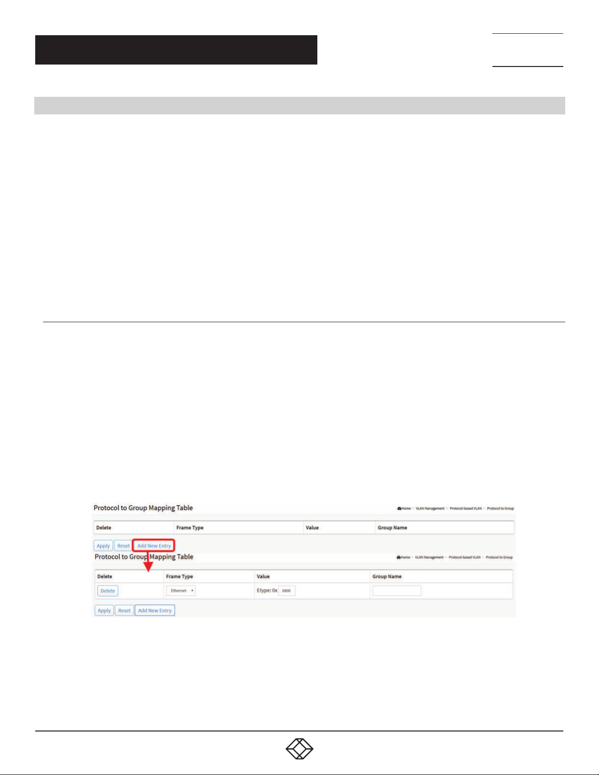
NEED HELP?
LEAV E TH E TEC H TO US
LIVE 24/7
CHAPTER 5: VLAN MANAGEMENT
TECHNICAL
SUPPORT
1. 87 7.8 77. 22 69
5.6 PROTOCOL-BASED VLAN
This section describes Protocol -based VLAN. The switch supports Ethernet LLC and SNAP protocols.
LLC
The Logical Link Control (LLC) data communication protocol layer is the upper sub-layer of the Data Link Layer (which is itself layer
2, just above the Physical Layer) in the seven-layer OSI reference model. It provides multiplexing mechanisms that make it possible
for several network protocols (IP, IPX, Decent and Appletalk) to coexist within a multipoint network and to be transported over the
same network media, and can also provide flow control and automatic repeat request (ARQ) error management mechanisms.
SNAP
The Subnetwork Access Protocol (SNAP) is a mechanism for multiplexing, on networks using IEEE 802.2 LLC, more protocols than
can be distinguished by the 8-bit 802.2 Service Access Point (SAP) fields. SNAP supports identifying protocols by Ethernet type
field values; it also supports vendor-private protocol identifier spaces. It is used with IEEE 802.3, IEEE 802.4, IEEE 802.5, IEEE 802.11
and other IEEE 802 physical network layers, as well as with non-IEEE 802 physical network layers such as FDDI that use 802.2 LLC.
5.6.1 PROTOCOL TO GROUP
This page allows you to add new protocols to Group Name (unique for each Group) mapping entries as well to allow you to see and
delete already mapped entries for the selected stack switch unit switch.
WEB INTERFACE
To configure Protocol -based VLAN configuration in the web interface:
1. Click VLAN Management, Protocol-based VLAN and Protocol to Group.
2. Click “Add New Entry”.
3. Specify the Ethernet LLC SNAP Protocol, Value and Group Name.
4. Click Apply.
FIGURE 5-7. PROTOCOL TO GROUP MAPPING TABLE
1. 8 7 7. 8 7 7. 2 2 6 9 BL ACK BO X.COM
59
Page 60

NEED HELP?
LEAV E TH E TEC H TO US
LIVE 24/7
CHAPTER 5: VLAN MANAGEMENT
PARAMETER DESCRIPTION
Frame Type: Frame Type can have one of the following values:
1. Ethernet
2. LLC
3. SNAP
NOTE: On changing the Frame type field, a valid value of the following text field will vary depending on the new frame type you
selected.
Value: A valid value that can be entered in this text field depends on the option selected from the preceding Frame Type selection
menu.
Below is the criteria for three different Frame Types:
1. For Ethernet: A value in the text field when Ethernet is selected as a Frame Type is called etype. Valid values for etype range from
0x0600-0xffff
2. For LLC: A valid value in this case is comprised of two different sub-values.
a. DSAP: 1-byte long string (0x00-0xff)
b. SSAP: 1-byte long string (0x00-0xff)
3. For SNAP: A valid value in this case also is comprised of two different sub-values.
a.OUI: OUI (Organizationally Unique Identifier) is a value in the format of xx-xx-xx where each pair (xx) in string is a hexadecimal value
ranging from 0x00-0xff.
b. PID: If the OUI is hexadecimal 000000, the protocol ID is the Ethernet type (EtherType) field value for the protocol running on top of
SNAP. If the OUI is an OUI for a particular organization, the protocol ID is a value assigned by that organization to the protocol running
on top of SNAP.
Group Name: A valid Group Name is a unique 16-character long string.
Buttons
Delete: To delete a Protocol to Group Name map entry, check this box. The entry will be deleted on the switch during the next Save.
Adding New Entry: Click to add a new entry in mapping table. An empty row is added to the table; Frame Type, Value and the Group
Name can be configured as needed. The button can be used to undo the addition of new entry.
Apply: Click to save changes.
Reset: Click to undo any changes made locally and revert to previously saved values.
TECHNICAL
SUPPORT
1. 87 7.8 77. 22 69
5.6.2 GROUP TO VLAN
This section allows you to map an already configured Group Name to a VLAN for the selected stack switch unit switch.
WEB INTERFACE
To configure a Group Name to VLAN mapping table in the web interface:
1. Click VLAN Management, Protocol-based VLAN and Group to Group.
2. Click “Add New Entry”.
3. Specify the Group Name and VLAN ID.
4. Click Apply.
60
1. 8 7 7. 8 7 7. 2 2 6 9 BL ACK BO X.COM
Page 61
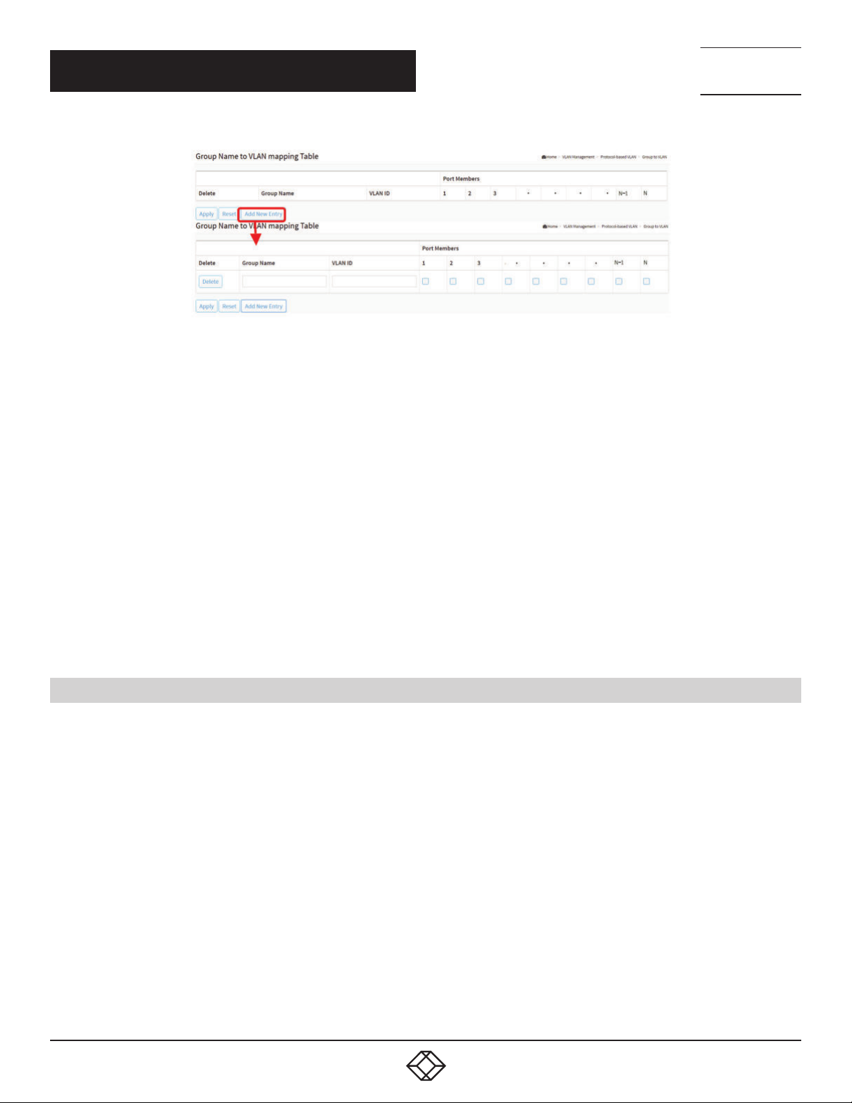
NEED HELP?
LEAV E TH E TEC H TO US
LIVE 24/7
CHAPTER 5: VLAN MANAGEMENT
TECHNICAL
SUPPORT
1. 87 7.8 77. 22 69
FIGURE 5-8. GROUP NAME OF VLAN MAPPING TABLE
PARAMETER DESCRIPTION
Group Name: A valid Group Name is a string of almost 16 characters.
VLAN ID: Indicates the ID to which Group Name will be mapped. A valid VLAN ID ranges from 1-4095.
Port Members: A row of check boxes for each port is displayed for each Group Name to VLAN ID mapping. To include a port in a
mapping, check the box. To remove or exclude the port from the mapping, make sure the box is unchecked. By default, no ports are
members, and all boxes are unchecked.
Buttons
Delete: To delete a Group Name to VLAN map entry, check this box. The entry will be deleted on the switch during the next Save.
Adding New Entry: Click to add a new entry in mapping table. An empty row is added to the table. The Group Name, VLAN ID and
port members can be configured as needed. Legal values for a VLAN ID are 1 through 4095. The button can be used to undo the
addition of a new entry.
Apply: Click to save changes.
Reset: Click to undo any changes made locally and revert to previously saved values.
5.7 IP SUBNET-BASED VLAN
The IP subnet-based VLAN entries can be configured here. This page allows for adding, updating and deleting IP subnet-based
VLAN entries.
WEB INTERFACE
To configure IP subnet-based VLAN Membership in the web interface:
1. Click VLAN Management and IP Subnet-based VLAN.
2. Click “Add New Entry”.
3. Specify IP Address, Mask Length, VLAN ID.
4. Click Apply.
1. 8 7 7. 8 7 7. 2 2 6 9 BL ACK BO X.COM
61
Page 62
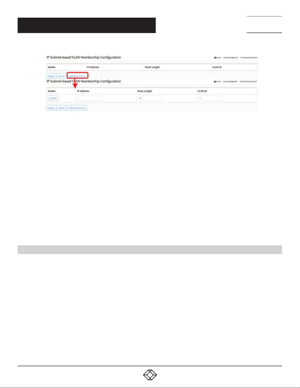
NEED HELP?
LEAV E TH E TEC H TO US
LIVE 24/7
CHAPTER 5: VLAN MANAGEMENT
FIGURE 5-9. IP SUBNET-BASED VLAN MEMBERSHIP CONFIGURATION
PARAMETER DESCRIPTION
IP Address: Indicates the IP address.
Mask Length: Indicates the network mask length.
VLAN ID: Indicates the VLAN ID. VLAN ID can be changed for the existing entries.
Buttons
Delete: To delete a IP subnet-based VLAN entry, check this box and press save. The entry will be deleted on the selected switch in
the stack.
Adding New Entry: Click “Add New Entry” to add a new IP subnet-based VLAN entry. An empty row is added to the table, and the
IP subnet-based VLAN entry can be configured as needed. Any IP address/mask can be configured for the IP subnet-based VLAN
entry. Legal values for a VLAN ID are 1 through 4095.
The IP subnet-based VLAN entry is enabled on the selected stack switch unit when you click on “Save”. The “Delete” button can be
used to undo the addition of new IP subnet-based VLANs. The maximum possible IP subnet-based VLAN entries are limited to 128.
Apply: Click to save changes.
Reset: Click to undo any changes made locally and revert to previously saved values.
TECHNICAL
SUPPORT
1. 87 7.8 77. 22 69
5.8 PRIVATE VL AN
The Private VLAN membership configurations for the switch can be monitored and modified here. Private VLANs can be added or
deleted here. Port members of each Private VLAN can be added or removed here.
Private VLANs are based on the source port mask, and there are no connections to VLANs. This means that VLAN IDs and Private
VLAN IDs can be identical.
A port must be a member of both a VLAN and a Private VLAN to be able to forward packets. By default, all ports are VLAN unaware
and members of VLAN 1 and Private VLAN 1.
A VLAN unaware port can only be a member of one VLAN, but it can be a member of multiple Private VLANs.
VLAN Priority: Voice VLAN > MAC based VLAN > Protocol based VLAN > Tag based VLAN
62
1. 8 7 7. 8 7 7. 2 2 6 9 BL ACK BO X.COM
Page 63
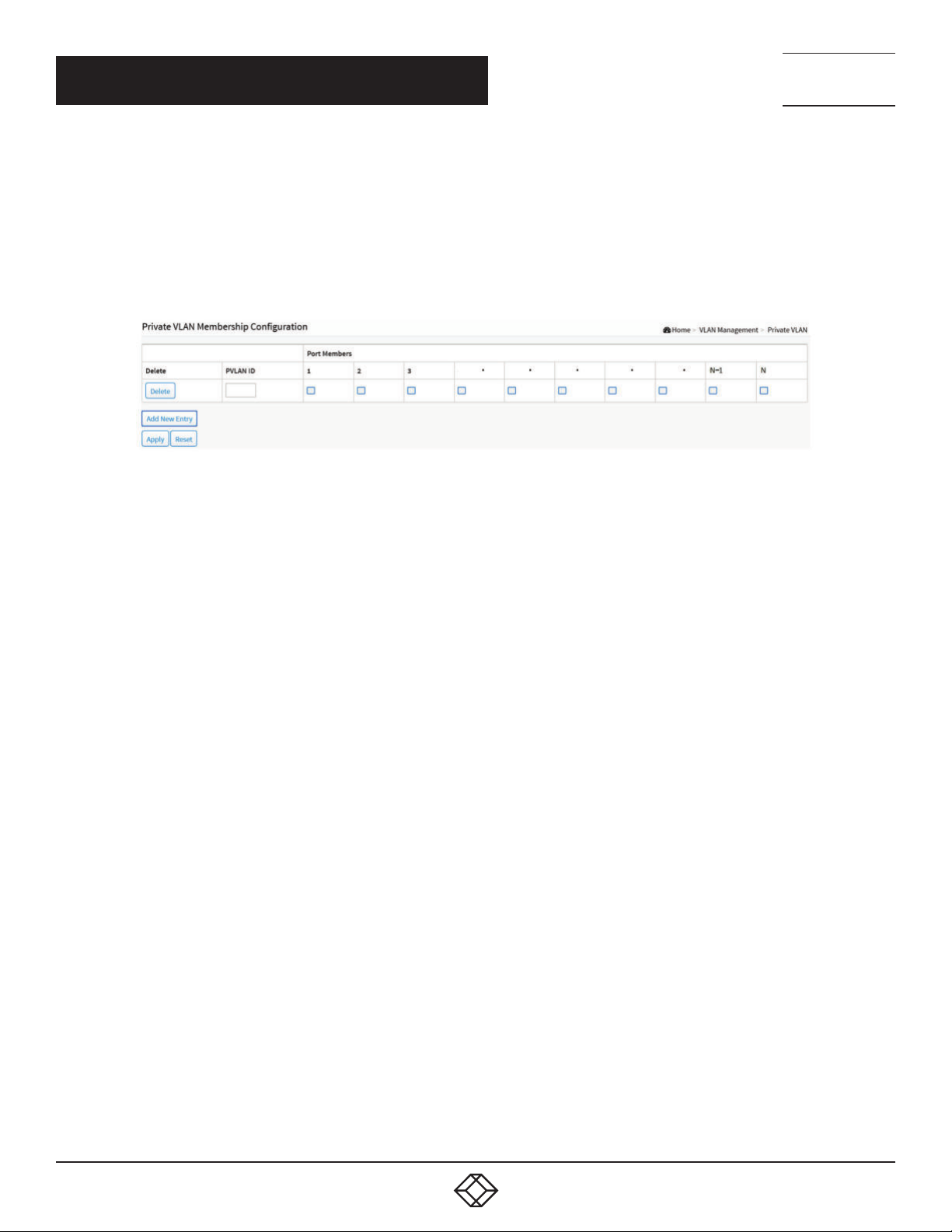
CHAPTER 5: VLAN MANAGEMENT
WEB INTERFACE
To configure Port Isolation in the web interface:
1. Click VLAN Management and Private VLAN.
2. Configure the Private VLAN membership for the switch.
3. Click Apply.
FIGURE 5-10. PRIVATE VLAN CONFIGURATION
NEED HELP?
LEAV E TH E TEC H TO US
LIVE 24/7
TECHNICAL
SUPPORT
1. 87 7.8 77. 22 69
PARAMETER DESCRIPTION
Delete: To delete a private VLAN entry, check this box. The entry will be deleted during the next apply.
Private VLAN ID: Indicates the ID of this particular private VLAN.
Port Members: A row of check boxes for each port is displayed for each private VLAN ID. To include a port in a Private VLAN, check
the box. To remove or exclude the port from the Private VLAN, make sure the box is unchecked. By default, no ports are members, and
all boxes are unchecked.
Adding New Private VLAN: Click to add a new private VLAN ID. An empty row is added to the table, and the private VLAN can be
configured as needed. The allowed range for a private VLAN ID is the same as the switch port number range. Any values outside this
range are not accepted, and a warning message appears. Click “OK” to discard the incorrect entry, or click “Cancel” to return to the
editing and make a correction.
The Private VLAN is enabled when you click “Apply”.
The button can be used to undo the addition of new Private VLANs.
Buttons
Apply: Click to save changes.
Reset: Click to undo any changes made locally and revert to previously saved values.
1. 8 7 7. 8 7 7. 2 2 6 9 BL ACK BO X.COM
63
Page 64

NEED HELP?
LEAV E TH E TEC H TO US
LIVE 24/7
CHAPTER 5: VLAN MANAGEMENT
TECHNICAL
SUPPORT
1. 87 7.8 77. 22 69
5.9 PORT ISOLATION
Port Isolation provides for an apparatus and method to isolate ports on layer 2 switches on the same VLAN to restrict traffic flow.
The apparatus comprises a switch having said plurality of ports, each port configured as a protected port or a non-protected port.
An address table memory stores an address table having a destination address and port number pair. A forwarding map generator
generates a forwarding map that is responsive to a destination address of a data packet. The method for isolating ports on a layer
2 switch comprises configuring each of the ports on the layer 2 switch as a protected port or a non-protected port. A destination
address on a data packet is matched with a physical address on said layer 2 switch and a forwarding map is generated for the
data packet based upon the destination address on the data packet. The data packet is then sent to the ports according to the
forwarding map generated based upon whether the ingress port was configured as a protected or non-protected port.
This page is used for enabling or disabling port isolation on ports in a Private VLAN. A port member of a VLAN can be isolated to
other isolated ports on the same VLAN and Private VLAN.
WEB INTERFACE
To configure Port Isolation in the web interface:
1. Click VLAN Management and Port Isolation.
2. Select the port to enable Port Isolation.
3. Click Apply.
FIGURE 5-11. PORT ISOLATION CONFIGURATION
PARAMETER DESCRIPTION
Port Numbers: A check box is provided for each port of a private VLAN. When checked, port isolation is enabled on that port. When
unchecked, port isolation is disabled on that port. By default, port isolation is disabled on all ports.
Buttons
Apply: Click to save changes.
Reset: Click to undo any changes made locally and revert to previously saved values.
64
1. 8 7 7. 8 7 7. 2 2 6 9 BL ACK BO X.COM
Page 65
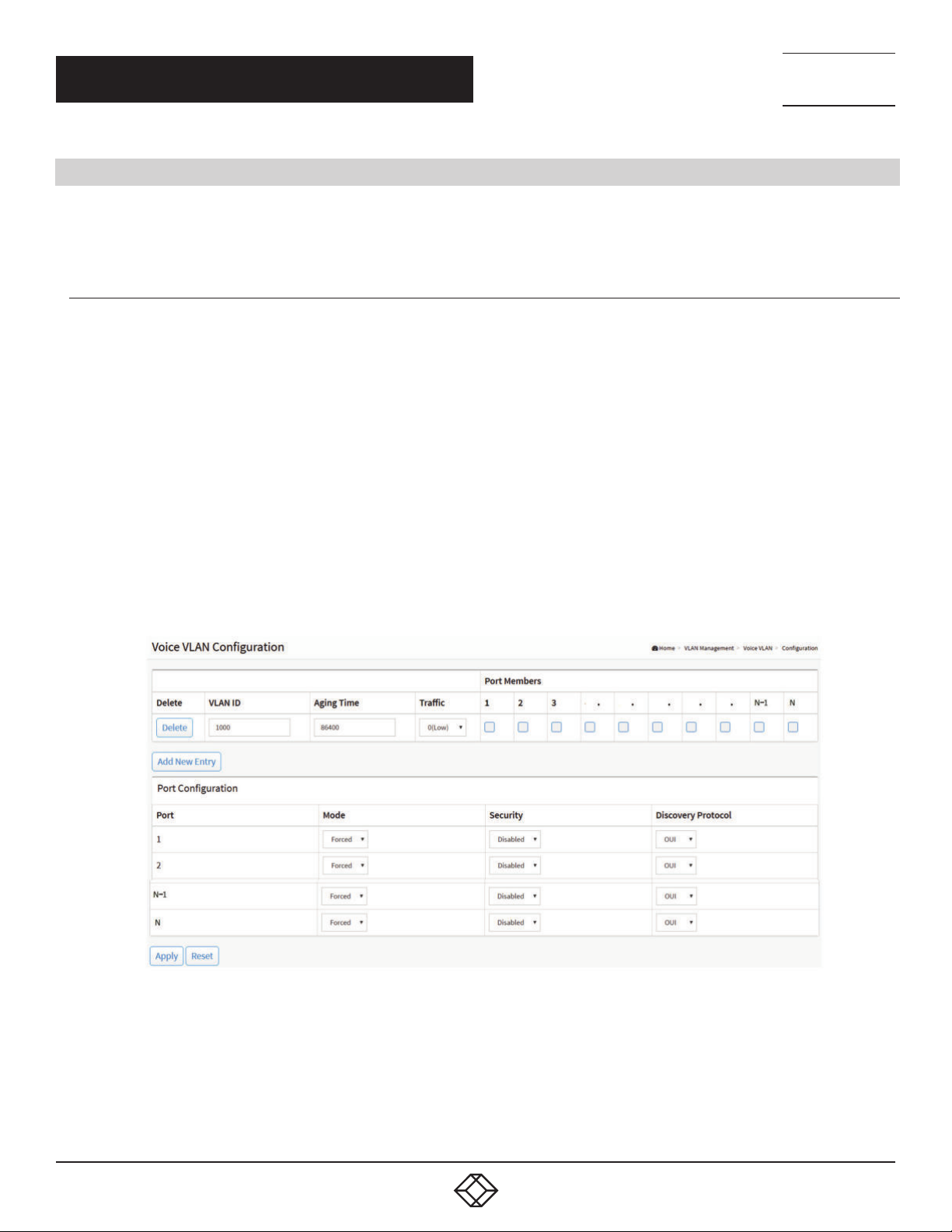
NEED HELP?
LEAV E TH E TEC H TO US
LIVE 24/7
CHAPTER 5: VLAN MANAGEMENT
TECHNICAL
SUPPORT
1. 87 7.8 77. 22 69
5.10 VOICE VLAN
Voice VLAN is VLAN configured specially for voice traffic. By adding the ports with voice devices attached to voice VLAN, you can
perform QoS-related configuration for voice data, ensuring the transmission priority of voice traffic and voice quality.
5.10.1 CONFIGURATION
The Voice VLAN feature enables voice traffic forwarding on the Voice VLAN, then the switch can classify and schedule network
traffic. We recommend that there be two VLANs on a port—one for voice, one for data. Before connecting the IP device to the
switch, the IP phone should configure the voice VLAN ID correctly. It should be configured through its own GUI.
WEB INTERFACE
To configure Voice VLAN in the web interface:
1. Click VLAN Management, Voice VLAN and Configuration.
2. Click “Add New Entry”.
3. Select Port Members in the Voice VLAN Configuration.
4. Specify VLAN ID, Aging Time, Traffic.
5. Specify (Mode, Security, Discovery Protocol) in the Port Configuration.
6. Click Apply.
FIGURE 5-12. VOICE VLAN CONFIGURATION
1. 8 7 7. 8 7 7. 2 2 6 9 BL ACK BO X.COM
65
Page 66

NEED HELP?
LEAV E TH E TEC H TO US
LIVE 24/7
CHAPTER 5: VLAN MANAGEMENT
PARAMETER DESCRIPTION
Port Members: Indicates the Voice VLAN port mode operation. Disable the MSTP feature before enabling Voice VLAN. This will avoid
the conflict of ingress filtering. Select the port for which you want to enable the Voice VLAN mode operation.
VLAN ID: Indicates the Voice VLAN ID. It should be a unique VLAN ID in the system and cannot equal each port PVID. It is a conflict in
configuration if the value equals management VID, MVR VID, PVID etc. The allowed range is 1 to 4095.
Aging Time: Indicates the Voice VLAN secure learning aging time. The allowed range is 10 to 10000000 seconds. It is used when
security mode or auto detect mode is enabled. In other cases, it will be based on hardware aging time. The actual aging time will be
situated between the [age_time; 2 * age_time] interval.
Traffic: Indicates the Voice VLAN traffic class. All traffic on the Voice VLAN will apply to this class.
Port Configuration
Port: The switch port number of the Voice VLAN port.
Mode: Indicates the Voice VLAN port mode.
When the port mode isn’t disabled, you must disable MSTP feature before you enable Voice VLAN. It can avoid the conflict of ingress
filtering.
Possible port modes are:
Auto: Enable auto detect mode. It detects whether there is a VoIP phone attached to the specific port and configures the Voice VLAN
members automatically.
Forced: Force join to Voice VLAN.
Security: Indicates the Voice VLAN port security mode. When the function is enabled, all non-telephonic MAC addresses in the Voice
VLAN will be blocked for 10 seconds. Possible port modes are:
Enabled: Enable Voice VLAN security mode operation.
Disabled: Disable Voice VLAN security mode operation.
Discovery Protocol: Indicates the Voice VLAN port discovery protocol. It will only work when auto detect mode is enabled. Enable the
LLDP feature before configuring discovery protocol to “LLDP” or “Both”. Changing the discovery protocol to “OUI” or “LLDP” will restart
auto detect process. Possible discovery protocols are:
OUI: Detect telephony device by OUI address.
LLDP: Detect telephony device by LLDP.
Both: Both OUI and LLDP.
Buttons
Add New entry: Click to add a new entry in Voice VLAN configuration.
Apply: Click to save changes.
Reset: Click to undo any changes made locally and revert to previously saved values.
TECHNICAL
SUPPORT
1. 87 7.8 77. 22 69
66
1. 8 7 7. 8 7 7. 2 2 6 9 BL ACK BO X.COM
Page 67
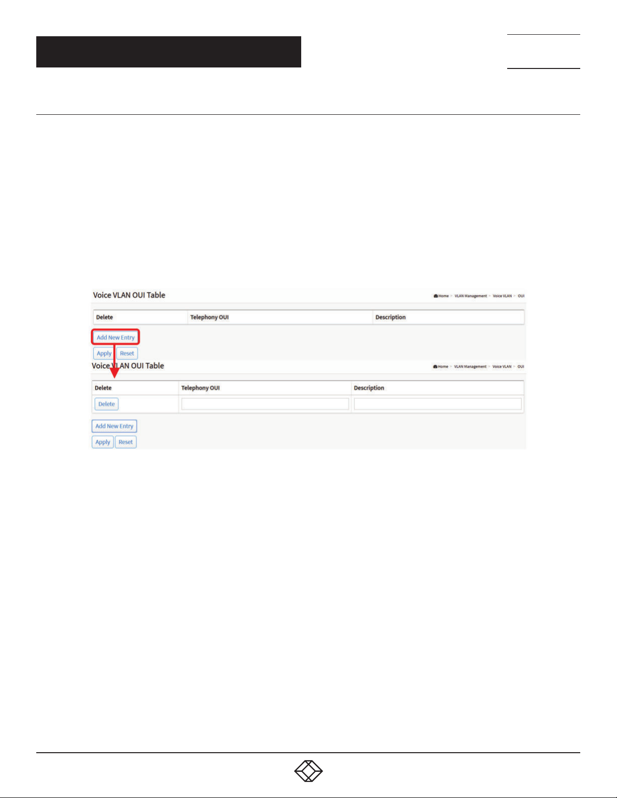
NEED HELP?
LEAV E TH E TEC H TO US
LIVE 24/7
CHAPTER 5: VLAN MANAGEMENT
TECHNICAL
SUPPORT
1. 87 7.8 77. 22 69
5.10.2 OUI
This section describes how to Configure VOICE VLAN OUI table. The maximum entry number is 16. Modifying the OUI table will
restart auto detection of the OUI process.
WEB INTERFACE
To configure a Voice VLAN OUI Table in the web interface:
1. Click VLAN Management, Voice VLAN and OUI.
2. Select “Add new entry”, “delete” in the Voice VLAN OUI table.
3. Specify Telephony OUI, Description.
4. Click Apply.
FIGURE 5-13. VOICE VL AN OUI TABLE
PARAMETER DESCRIPTION
Delete: Check to delete the entry. It will be deleted during the next save.
Telephony OUI: A telephony OUI address is a globally unique identifier assigned to a vendor by IEEE. It must be 6 characters long and
the input format is “xx-xx-xx” (x is a hexadecimal digit).
Description: The description of OUI address. Normally, it describes which vendor telephony device it belongs to. The allowed string
length is 0 to 32.
Add New entry: Click to add a new entry in Voice VLAN OUI table. An empty row is added to the table, the Telephony OUI, Description.
Buttons
Apply: Click to save changes.
Reset: Click to undo any changes made locally and revert to previously saved values.
1. 8 7 7. 8 7 7. 2 2 6 9 BL ACK BO X.COM
67
Page 68
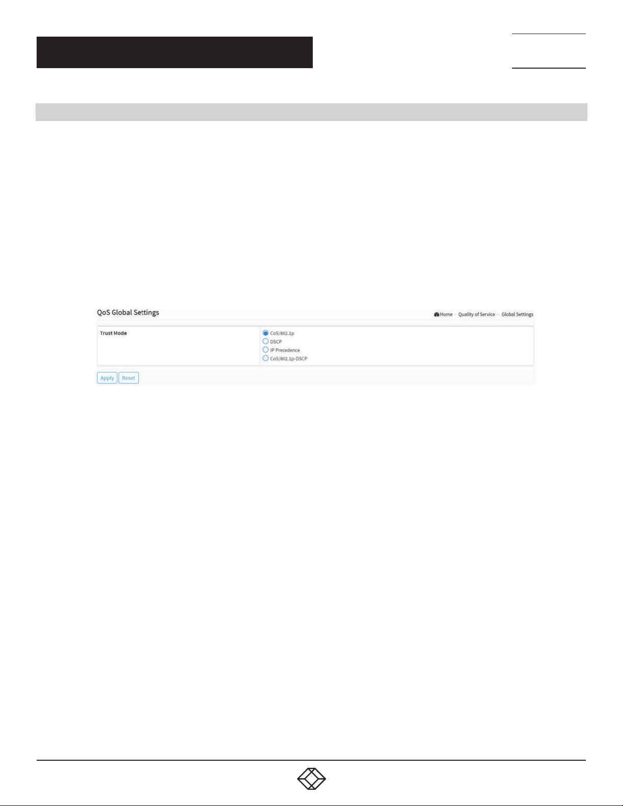
NEED HELP?
LEAV E TH E TEC H TO US
LIVE 24/7
CHAPTER 6: QUALITY OF SERVICE
6.1 GLOBAL SETTINGS
Use the Global Settings page to set the trust behavior for QoS basic mode. This configuration is active when the switch is in QoS
basic mode. Packets entering a QoS domain are classified at the edge of the QoS domain.
WEB INTERFACE
To configure the Global Settings in the web interface:
1. Click Quality of Service and Global Settings.
2. Select the trust mode when the switch is in QoS basic mode. If a packet CoS level and DSCP tag are mapped to separate queues,
the trust mode determines the queue to which the packet is assigned.
3. Click Apply to save the configuration.
4. If you want to cancel the setting, then you need to click the Reset button. It will revert to previously saved values.
TECHNICAL
SUPPORT
1. 87 7.8 77. 22 69
FIGURE 6-1. QOS GLOBAL SETTINGS
PARAMETER DESCRIPTION
Trus t Mode
CoS/802.1p: Traffic is mapped to queues based on the VPT field in the VLAN tag, or based on the per-port default CoS/802.1p value
(if there is no VLAN tag on the incoming packet). The actual mapping of the VPT to queue can be configured on the CoS/802.1p to
Queue page.
DSCP: All IP traffic is mapped to queues based on the DSCP field in the IP header. The actual mapping of the DSCP to queue can be
configured on the DSCP to Queue page. If traffic is not IP traffic, it is mapped to the best effort queue.
IP Precedence: Traffic is mapped to queues based on the IP precedence. The actual mapping of the IP precedence to queue can be
configured on the IP Precedence to Queue page.
CoS/802.1p-DSCP: Uses the trust CoS mode for non-IP traffic and trust DSCP mode for IP traffic.
Buttons
Apply: Click to save changes.
Reset: Click to undo any changes made locally and revert to previously saved values.
68
1. 8 7 7. 8 7 7. 2 2 6 9 BL ACK BO X.COM
Page 69
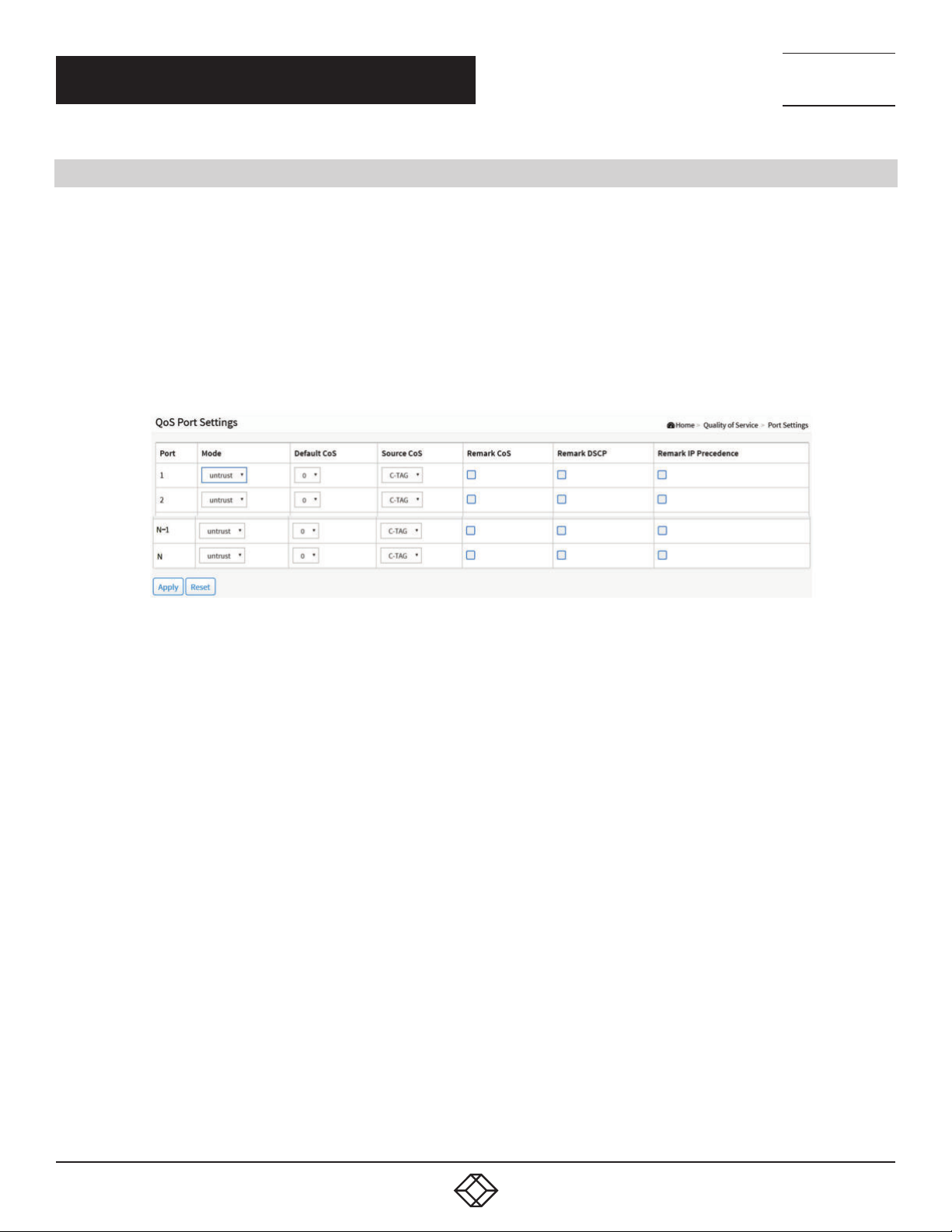
CHAPTER 6: QUALITY OF SERVICE
6.2 PORT SETTINGS
WEB INTERFACE
To configure the QoS Port Setting in the web interface:
1. Click Quality of Service and Port Settings.
2. Select Mode, Default CoS, Source CoS, Remark CoS to each port.
3. Click the port to enable the Remark Cos, Remark DSCP, Remark IP Precedence.
4. Click Apply to save the configuration.
5. If you want to cancel the setting, then you need to click the Reset button. It will revert to previously saved values.
NEED HELP?
LEAV E TH E TEC H TO US
LIVE 24/7
TECHNICAL
SUPPORT
1. 87 7.8 77. 22 69
FIGURE 6-2. QOS PORT SETTINGS
PARAMETER DESCRIPTION
Port: The logical port for the settings contained in the same row.
Mode:
- Untrust: All ingress traffic on the port is mapped to the best effort queue and no classification/prioritization takes place.
- Trust: Port prioritize ingress traffic is based on the system-wide configured trusted mode, which is either CoS/802.1p trusted mode,
IP Precedence trusted mode or DSCP trusted mode.
Default CoS: Select the default CoS value to be assigned for incoming untagged packets. The range is 0 to 7.
Source CoS: The CoS value is determined based on C-Tag or S-Tag for incoming tagged packets
Remark CoS: Click the checkbox to remark the CoS/802.1p priority for egress traffic on this port.
Remark DSCP: Click the checkbox to remark the DSCP value for egress traffic on this port.
Remark IP Precedence: Click the checkbox to remark the IP precedence for egress traffic on this port.
NOTE: The CoS/802.1p priority and IP Precedence, or the CoS/802.1p priority and DSCP value can be remarked simultaneously for
egress traffic on a port, but the DSCP value and IP Precedence cannot be remarked simultaneously.
Buttons
Apply: Click to save changes.
Reset: Click to undo any changes made locally and revert to previously saved values.
1. 8 7 7. 8 7 7. 2 2 6 9 BL ACK BO X.COM
69
Page 70
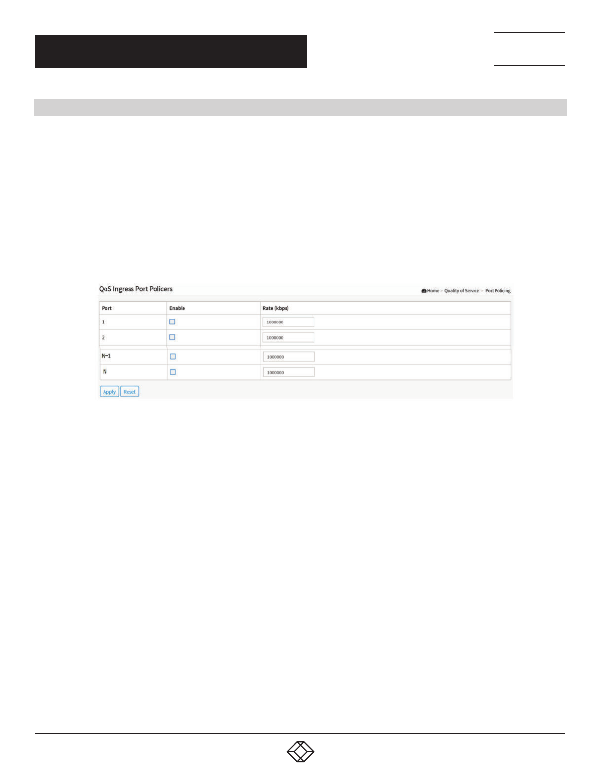
NEED HELP?
LEAV E TH E TEC H TO US
LIVE 24/7
CHAPTER 6: QUALITY OF SERVICE
6.3 PORT POLICING
This section provides an overview of QoS Ingress Port Policers for all switch ports Port Policing is useful in constraining traffic
flows and marking frames above specific rates. Policing is primarily useful for data flows and voice or video flows, because voice
and video usually maintains a steady rate of traffic.
WEB INTERFACE
To configure the QoS Port Policers in the web interface:
1. Click Quality of Service and Port Policing.
2. Click the port need to enable the QoS Ingress Port Policers, and configure the Rate limit condition.
3. Click Apply to save the configuration.
4. If you want to cancel the setting, click the Reset button. It will revert to previously saved values.
TECHNICAL
SUPPORT
1. 87 7.8 77. 22 69
FIGURE 6-3. QOS INGRESS PORT POLICERS CONFIGURATION
PARAMETER DESCRIPTION
Port: The logical port for the settings contained in the same row. Click on the port number to configure the schedulers.
Enabled: Enable the QoS Ingress Port Policers function for a port.
Rate: Set the Rate limit value for this port, the default is 1000000.
Buttons
Apply: Click to save changes.
Reset: Click to undo any changes made locally and revert to previously saved values.
70
1. 8 7 7. 8 7 7. 2 2 6 9 BL ACK BO X.COM
Page 71
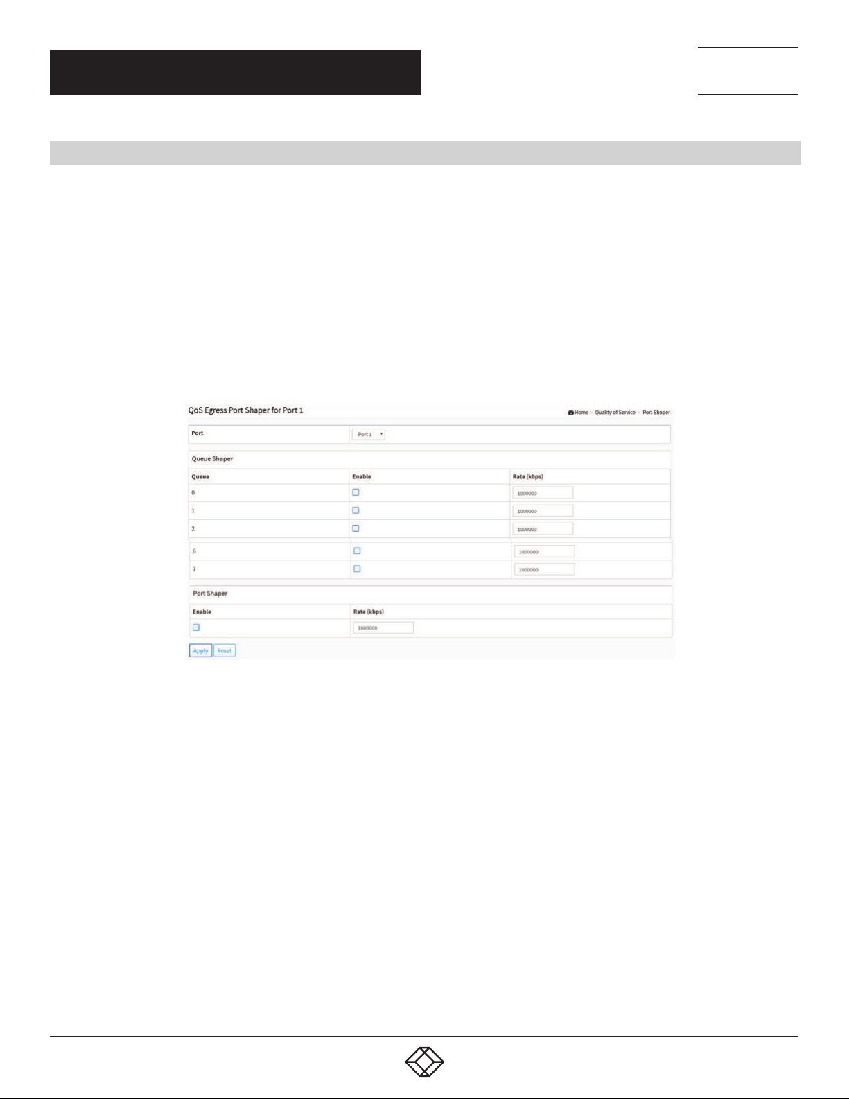
NEED HELP?
LEAV E TH E TEC H TO US
LIVE 24/7
CHAPTER 6: QUALITY OF SERVICE
6.4 PORT SHAPER
This section provides an overview of QoS Egress Port Shapers for all switch ports. Users can get detailed information for the ports
that belong to the currently selected stack unit.
WEB INTERFACE
To configure the QoS Port Shapers in the web interface:
1. Click Quality of Service and Port Shaper.
2. Select the port to configure QoS Egress Port Shaper.
3. Click the port to enable, and configure the Rate limit condition.
4. Click Apply to save the configuration.
5. If you want to cancel the setting, then you need to click the Reset button. It will revert to previously saved values.
TECHNICAL
SUPPORT
1. 87 7.8 77. 22 69
FIGURE 6-4. QOS EGRESS PORT SHAPER
PARAMETER DESCRIPTION
Port: The logical port for the settings contained in the same row. Click on the port number i to configure the shapers.
Queue Shaper
Queue: The queue number of the queue shaper on this switch port.
Enable: Controls whether the queue shaper is enabled for this queue on this switch port.
Rate(kbps): Controls the rate for the queue shaper. The default value is 1000000.
Port Shaper
Enable: Controls whether the port shaper is enabled for this switch port.
Rate(kbps): Controls the rate for the port shaper. The default value is 1000000.
Buttons
Apply: Click to save changes.
Reset: Click to undo any changes made locally and revert to previously saved values.
1. 8 7 7. 8 7 7. 2 2 6 9 BL ACK BO X.COM
71
Page 72
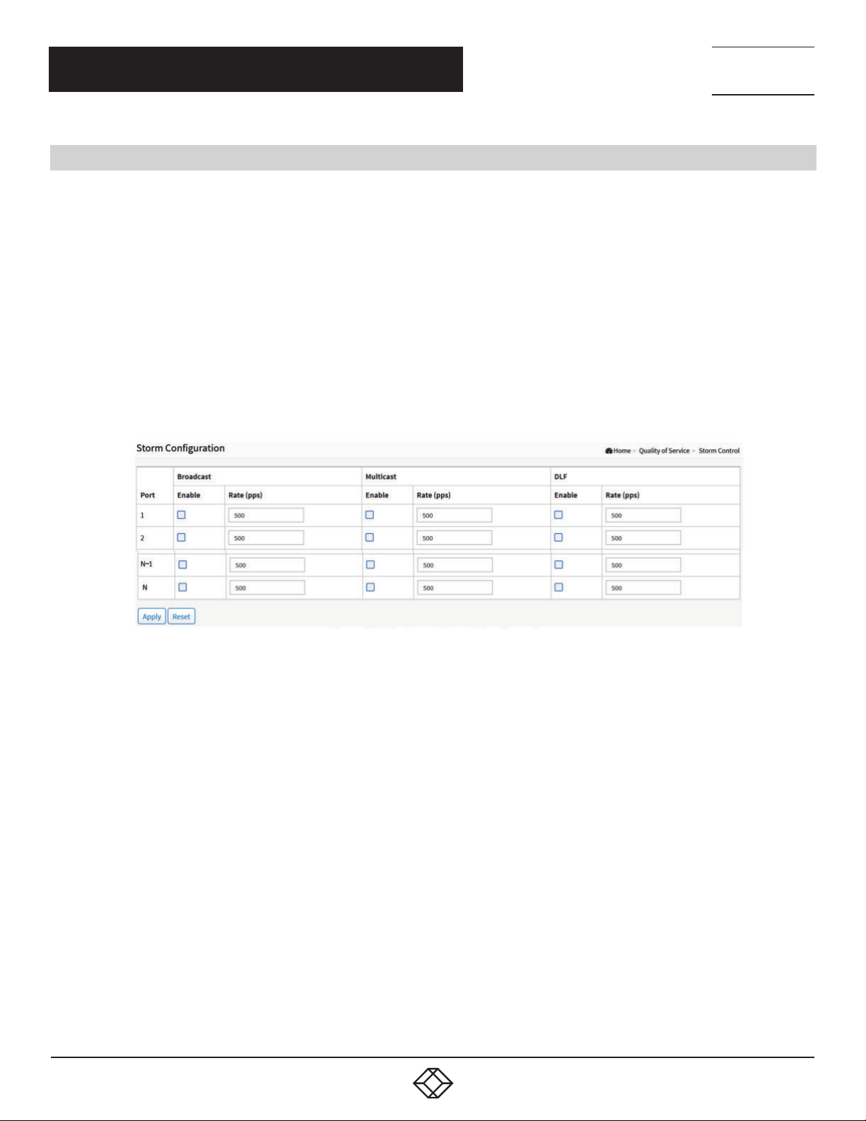
NEED HELP?
LEAV E TH E TEC H TO US
LIVE 24/7
CHAPTER 6: QUALITY OF SERVICE
TECHNICAL
SUPPORT
1. 87 7.8 77. 22 69
6.5 STORM CONTROL
This section shows users how to configure the Storm control for the switch. There is a destination lookup failure storm rate control,
multicast storm rate control, and a broadcast storm rate control. These only affect flooded frames, i.e. frames with a (VLAN ID,
DMAC) pair not present on the MAC Address table. The configuration indicates the permitted packet rate for unicast, multicast or
broadcast traffic across the switch
WEB INTERFACE
To configure the Storm Control Configuration parameters in the web interface:
1. Click Quality of Service and Storm Control.
2. Click which port need to enable, and configure the Rate limit condition.
4. Click the Apply to save the setting
5. If you want to cancel the setting then you need to click the Reset button. It will revert to previously saved values.
FIGURE 6-5. STORM CONTROL CONFIGURATION
PARAMETER DESCRIPTION
Port: The logical port for the settings contained in the same row. Click on the port number to configure the storm control.
Frame Type: The settings in a particular row apply to the frame type listed here: Broadcast, Multicast or DLF (destination lookup
failure).
Enable: Enable or disable the storm control status for the given frame type.
Rate: The rate unit is packets per second (pps). Valid values are: 0–262143 (pps). The 1 kpps is actually 1002.1 pps.
Buttons
Apply: Click to save changes.
Reset: Click to undo any changes made locally and revert to previously saved values.
72
1. 8 7 7. 8 7 7. 2 2 6 9 BL ACK BO X.COM
Page 73
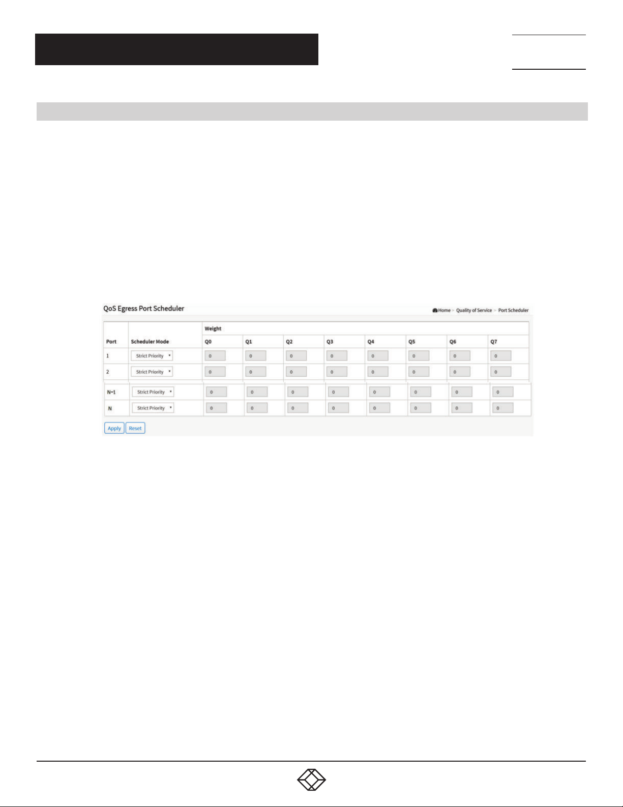
NEED HELP?
LEAV E TH E TEC H TO US
LIVE 24/7
CHAPTER 6: QUALITY OF SERVICE
TECHNICAL
SUPPORT
1. 87 7.8 77. 22 69
6.6 PORT SCHEDULER
This section provides an overview of QoS Egress Port Scheduler for all switch ports. and the ports belong to the currently selected
stack unit, as reflected by the page header.
WEB INTERFACE
To configure the QoS Port Schedulers in the web interface:
1. Click Quality of Service and Port Scheduler.
2. Select Scheduler Mode for each port.
3. If you select WRR or WFQ, you can configure weight.
4. Click Apply to save the setting.
5. If you want to cancel the setting, then you need to click the Reset button. It will revert to previously saved values.
FIGURE 6-6. QOS EGRESS PORT SCHEDULES
PARAMETER DESCRIPTION
Port: The logical port for the settings contained in the same row.
Scheduler Mode: Controls whether the scheduler mode is “Strict Priority”, “WRR” or “WFQ” on this switch port.
Weight: Controls the weight for this queue. The default value is “0”. This value is restricted to 0-127. This parameter is only shown if
“Scheduler Mode” is set to “Weighted”.
Buttons
Apply: Click to save changes.
Reset: Click to undo any changes made locally and revert to previously saved values.
1. 8 7 7. 8 7 7. 2 2 6 9 BL ACK BO X.COM
73
Page 74
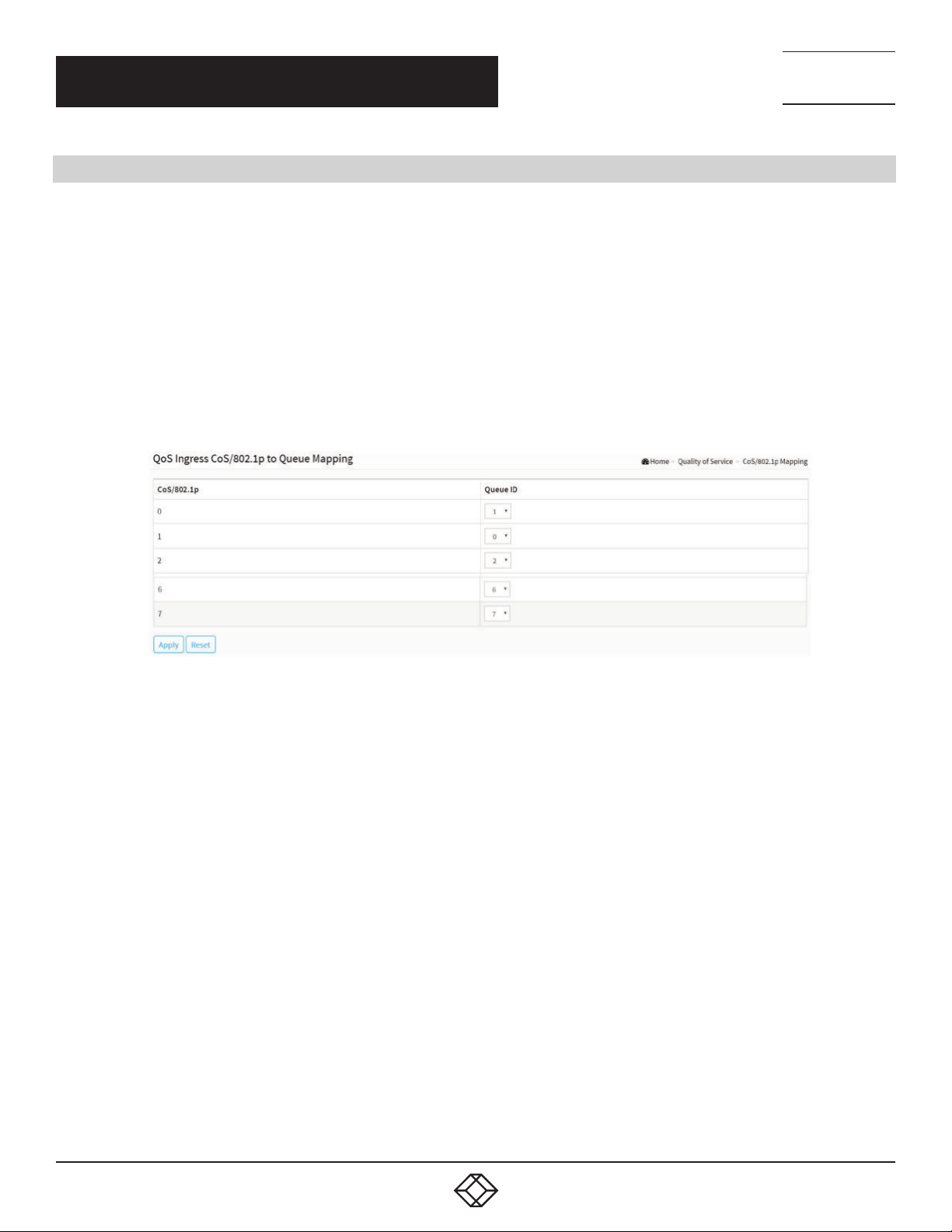
NEED HELP?
LEAV E TH E TEC H TO US
LIVE 24/7
CHAPTER 6: QUALITY OF SERVICE
6.7 C O S / 8 0 2 .1P M A P P I N G
Use the CoS/802.1p to Queue page to map 802.1p priorities to egress queues. The CoS/802.1p to Queue table determines the
egress queues of the incoming packets based on the 802.1p priority in their VLAN tags. For incoming untagged packets, the 802.1p
priority will be the default CoS/802.1p priority assigned to the ingress ports.
WEB INTERFACE
To configure the Cos/802.1p Mapping in the web interface:
1. Click Quality of Service and Cos/802.1p Mapping.
2. Select Queue ID.
3. Click Apply to save the setting.
4. If you want to cancel the setting, then you need to click the Reset button. It will revert to previously saved values.
TECHNICAL
SUPPORT
1. 87 7.8 77. 22 69
FIGURE 6-7. QOS INGRESS COS/802.1P TO QUEUE MAPPING
PARAMETER DESCRIPTION
CoS/802.1p: Displays the 802.1p priority tag values to be assigned to an egress queue, where 0 is the lowest and 7 is the highest
priority.
Queue ID: Select the egress queue to which the 802.1p priority is mapped. Eight egress queues are supported, where Queue 7 is the
highest priority egress queue and Queue 0 is the lowest priority egress queue.
Buttons
Apply: Click to save changes.
Reset: Click to undo any changes made locally and revert to previously saved values.
74
1. 8 7 7. 8 7 7. 2 2 6 9 BL ACK BO X.COM
Page 75
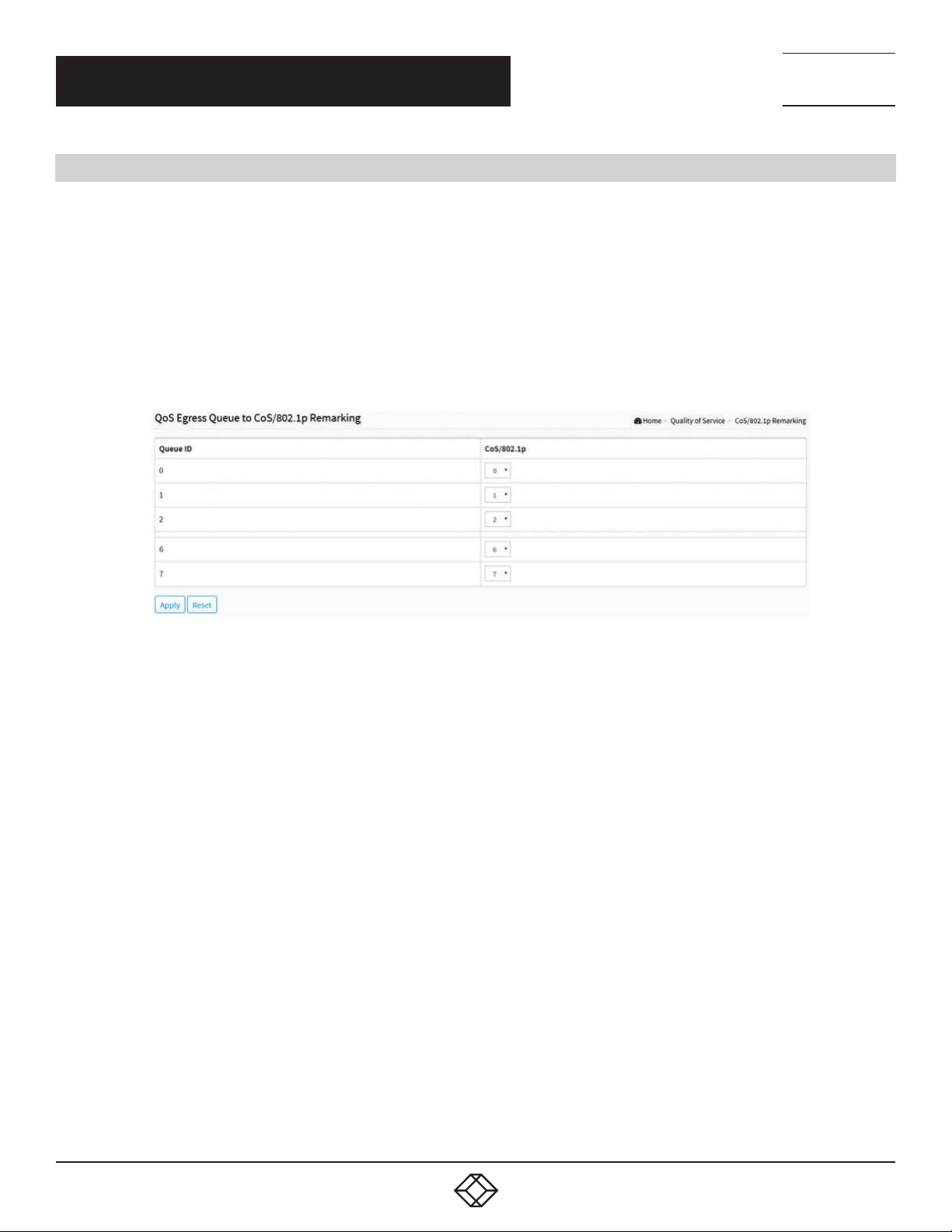
CHAPTER 6: QUALITY OF SERVICE
6.8 COS/802.1P REMARKING
Use the Queues to CoS/802.1p page to remark the CoS/802.1p priority for egress traffic from each queue.
WEB INTERFACE
To configure the Cos/802.1p Remarking in the web interface:
1. Click Quality of Service and Cos/802.1p Remarking.
2. Select CoS/802.1p.
3. Click Apply to save the setting.
4. If you want to cancel the setting, then you need to click the Reset button. It will revert to previously saved values.
NEED HELP?
LEAV E TH E TEC H TO US
LIVE 24/7
TECHNICAL
SUPPORT
1. 87 7.8 77. 22 69
FIGURE 6-8. QOS EGRESS QUEUE TO COS/802.1P REMARKING
PARAMETER DESCRIPTION
Queue ID: Displays the Queue ID, where Queue 7 is the highest priority egress queue and Queue 0 is the lowest priority egress queue.
CoS/802.1p: For each output queue, select the CoS/802.1p priority to which egress traffic from the queue is remarked.
Buttons
Apply: Click to save changes.
Reset: Click to undo any changes made locally and revert to previously saved values.
1. 8 7 7. 8 7 7. 2 2 6 9 BL ACK BO X.COM
75
Page 76
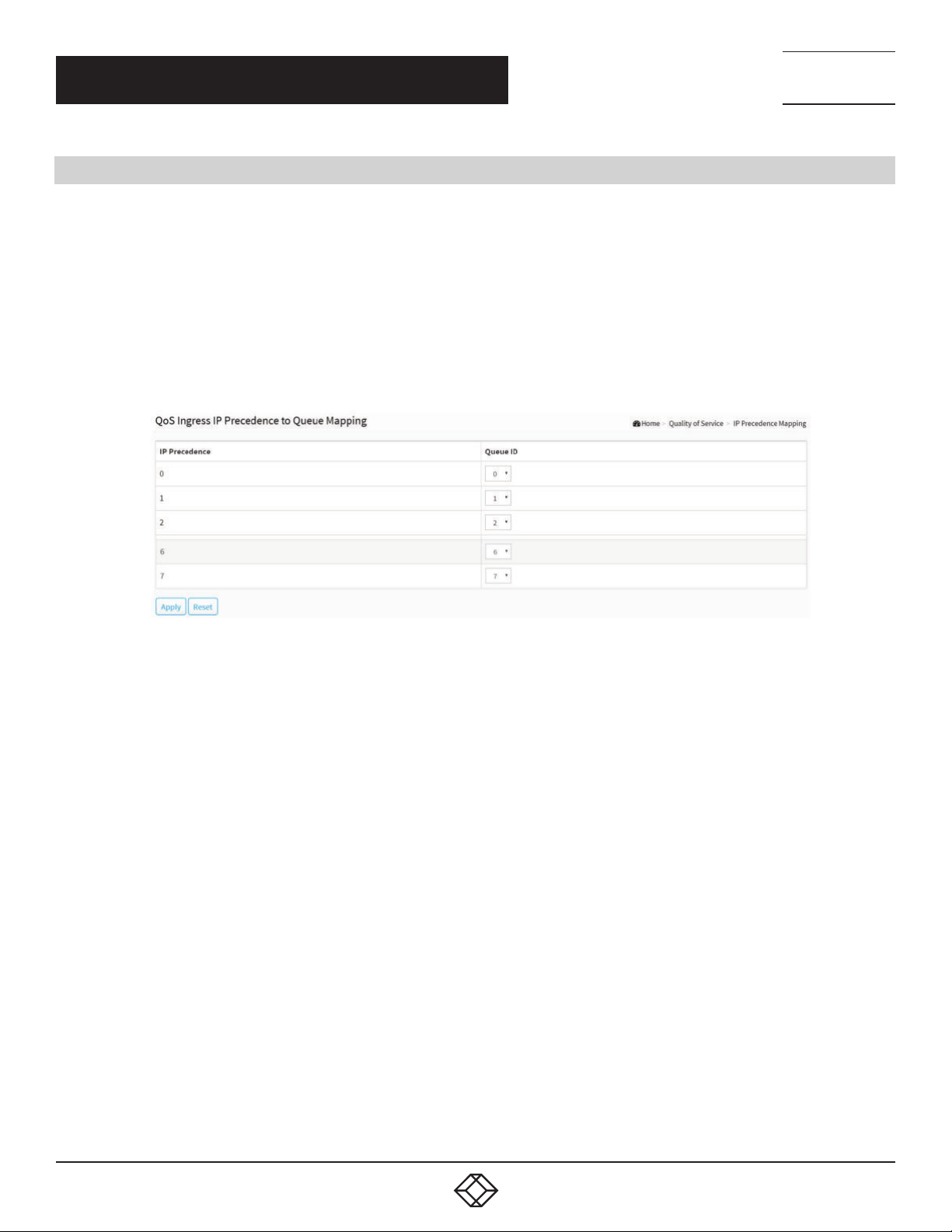
CHAPTER 6: QUALITY OF SERVICE
6.9 IP PRECEDENCE MAPPING
This section explains how to map IP precedence to an egress queue.
WEB INTERFACE
To configure the IP Precedence Mapping in the web interface:
1. Click Quality of Service and IP Precedence Mapping.
2. Select Queue ID.
3. Click Apply to save the setting.
4. If you want to cancel the setting, then you need to click the Reset button. It will revert to previously saved values.
NEED HELP?
LEAV E TH E TEC H TO US
LIVE 24/7
TECHNICAL
SUPPORT
1. 87 7.8 77. 22 69
FIGURE 6-9. QOS INRESS IP PRECEDENCE TO QUEUE MAPPING
PARAMETER DESCRIPTION
IP Precedence: Displays the IP Precedence priority tag values to be assigned to an egress queue, where 0 is the lowest and 7 is the
highest priority.
Queue ID: Select the egress queue to which the IP precedence priority is mapped. Eight egress queues are supported, where Queue
7 is the highest priority egress queue and Queue 0 is the lowest priority egress queue.
Buttons
Apply: Click to save changes.
Reset: Click to undo any changes made locally and revert to previously saved values.
76
1. 8 7 7. 8 7 7. 2 2 6 9 BL ACK BO X.COM
Page 77
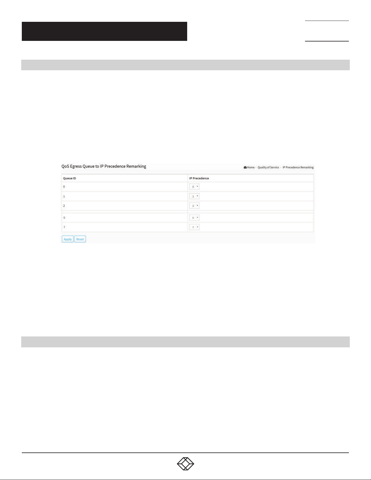
CHAPTER 6: QUALITY OF SERVICE
6.10 IP PRECEDENCE REMARKING
This section explains how to map an egress queue to IP precedence.
WEB INTERFACE
To configure the IP Precedence Remarking in the web interface:
1. Click Quality of Service and IP Precedence Remarking.
2. Select IP Precedence.
3. Click Apply to save the setting.
4. If you want to cancel the setting, then you need to click the Reset button. It will revert to previously saved values.
NEED HELP?
LEAV E TH E TEC H TO US
LIVE 24/7
TECHNICAL
SUPPORT
1. 87 7.8 77. 22 69
FIGURE 6-10. QOS ERESS QUEUE TO IP PRECEDENCE REMARKING
PARAMETER DESCRIPTION
Queue ID: Displays the Queue ID, where Queue 7 is the highest priority egress queue and Queue 0 is the lowest priority egress queue.
IP Precedence: For each output queue, select the IP Precedence priority to which egress traffic from the queue is remarked.
Buttons
Apply: Click to save changes.
Reset: Click to undo any changes made locally and revert to previously saved values.
6.11 DSCP MAPPING
Use the DSCP to Queue page to map IP DSCP to egress queues. The DSCP to Queue table determines the egress queues of the
incoming IP packets based on their DSCP values. The original VLAN Priority Tag (VPT) of the packet is unchanged.
It is possible to achieve the desired QoS in a network by simply changing the DSCP to Queue mapping, the queue schedule method,
and bandwidth allocation.
WEB INTERFACE
To configure the DSCP Mapping in the web interface:
1. Click Quality of Service and DSCP Mapping.
2. Select Queue ID.
1. 8 7 7. 8 7 7. 2 2 6 9 BL ACK BO X.COM
77
Page 78
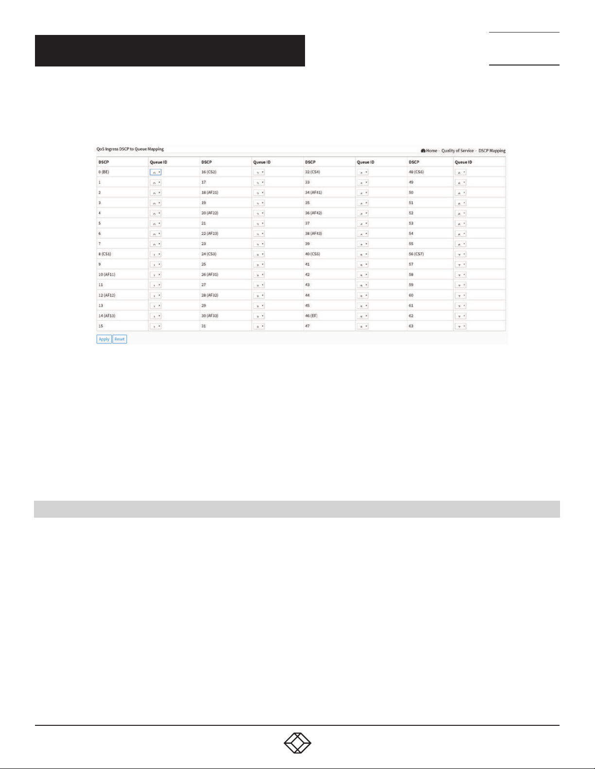
CHAPTER 6: QUALITY OF SERVICE
3. Click Apply to save the setting.
4. If you want to cancel the setting, then you need to click the Reset button. It will revert to previously saved values.
NEED HELP?
LEAV E TH E TEC H TO US
LIVE 24/7
TECHNICAL
SUPPORT
1. 87 7.8 77. 22 69
FIGURE 6-11. QOS INRESS DSCP TO QUEUE MAPPING
PARAMETER DESCRIPTION
DSCP: Displays the DSCP value in the incoming packet and its associated class.
Queue ID: Select the traffic forwarding queue from the Output Queue drop-down menu to which the DSCP value is mapped.
Buttons
Apply: Click to save changes.
Reset: Click to undo any changes made locally and revert to previously saved values.
6.12 DSCP REMARKING
Use the Queues to DSCP page to remark DSCP value for egress traffic from each queue.
WEB INTERFACE
To configure the DSCP Remarking in the web interface:
1. Click Quality of Service and DSCP Remarking.
2. Select DSCP.
3. Click apply to save the setting.
4. If you want to cancel the setting, then you need to click the Reset button. It will revert to previously saved values.
78
1. 8 7 7. 8 7 7. 2 2 6 9 BL ACK BO X.COM
Page 79
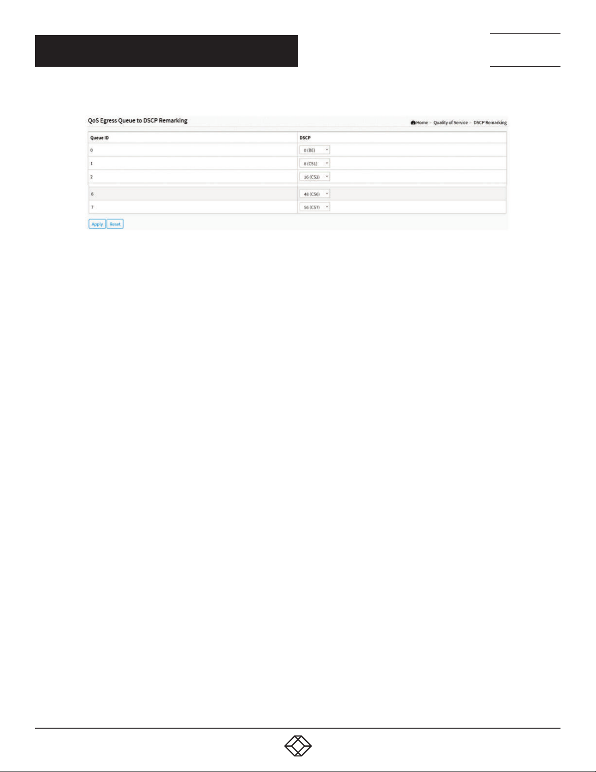
NEED HELP?
LEAV E TH E TEC H TO US
LIVE 24/7
CHAPTER 6: QUALITY OF SERVICE
FIGURE 6-12. QOS ERESS QUEUE TO DSCP REMARKING
PARAMETER DESCRIPTION
Queue ID: Displays the Queue ID, where Queue 7 is the highest priority egress queue and Queue 0 is the lowest priority egress queue.
DSCP: For each output queue, select the DSCP priority to which egress traffic from the queue is remarked.
Buttons
Apply: Click to save changes.
Reset: Click to undo any changes made locally and revert to previously saved values.
TECHNICAL
SUPPORT
1. 87 7.8 77. 22 69
1. 8 7 7. 8 7 7. 2 2 6 9 BL ACK BO X.COM
79
Page 80
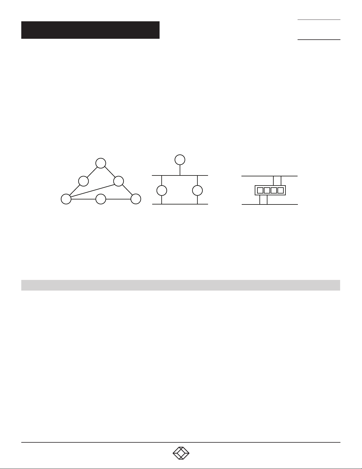
NEED HELP?
LEAV E TH E TEC H TO US
LIVE 24/7
CHAPTER 7: SPANNING TREE
The Spanning Tree Protocol (STP) can be used to detect and disable network loops, and to provide backup links between switches,
bridges or routers. This allows the switch to interact with other bridging devices (that is, an STP-compliant switch, bridge or
router) in your network to ensure that only one route exists between any two stations on the network, and provide backup links that
automatically take over when a primary link goes down.
STP - STP uses a distributed algorithm to select a bridging device (STP- compliant switch, bridge or router) that serves as the root
of the spanning tree network. It selects a root port on each bridging device (except for the root device) that incurs the lowest path
cost when forwarding a packet from that device to the root device. Then it selects a designated bridging device from each LAN
that incurs the lowest path cost when forwarding a packet from that LAN to the root device. All ports connected to designated
bridging devices are assigned as designated ports. After determining the lowest cost spanning tree, it enables all root ports and
designated ports, and disables all other ports. Network packets are therefore only forwarded between root ports and designated
ports, eliminating any possible network loops.
DESIGNATED
ROOT
TECHNICAL
SUPPORT
1. 87 7.8 77. 22 69
X
X
DESIGNATED
BRIDGE
X
FIGURE 7-1. SPANNING TREE PROTOCOL
Once a stable network topology has been established, all bridges listen for Hello BPDUs (Bridge Protocol Data Units) transmitted
from the Root Bridge. If a bridge does not get a Hello BPDU after a predefined interval (Maximum Age), the bridge assumes that
the link to the Root Bridge is down. This bridge will then initiate negotiations with other bridges to reconfigure the network to
reestablish a valid network topology.
7.1 S T AT E
This section describes how to select enable spanning tree protocol or not, and how to select the protocol version you want.
WEB INTERFACE
To configure the Spanning Tree Protocol version in the web interface:
1. Click Spanning Tree and state.
2. Enable or disable the Spanning Tree Protocol.
3. Select the Spanning Tree Protocol version.
4. Click apply to save the setting.
5. If you want to cancel the setting, then you need to click the Reset button. It will revert to previously saved values.
DESIGNATED
PORT
X
X
ROOT PORT
80
1. 8 7 7. 8 7 7. 2 2 6 9 BL ACK BO X.COM
Page 81
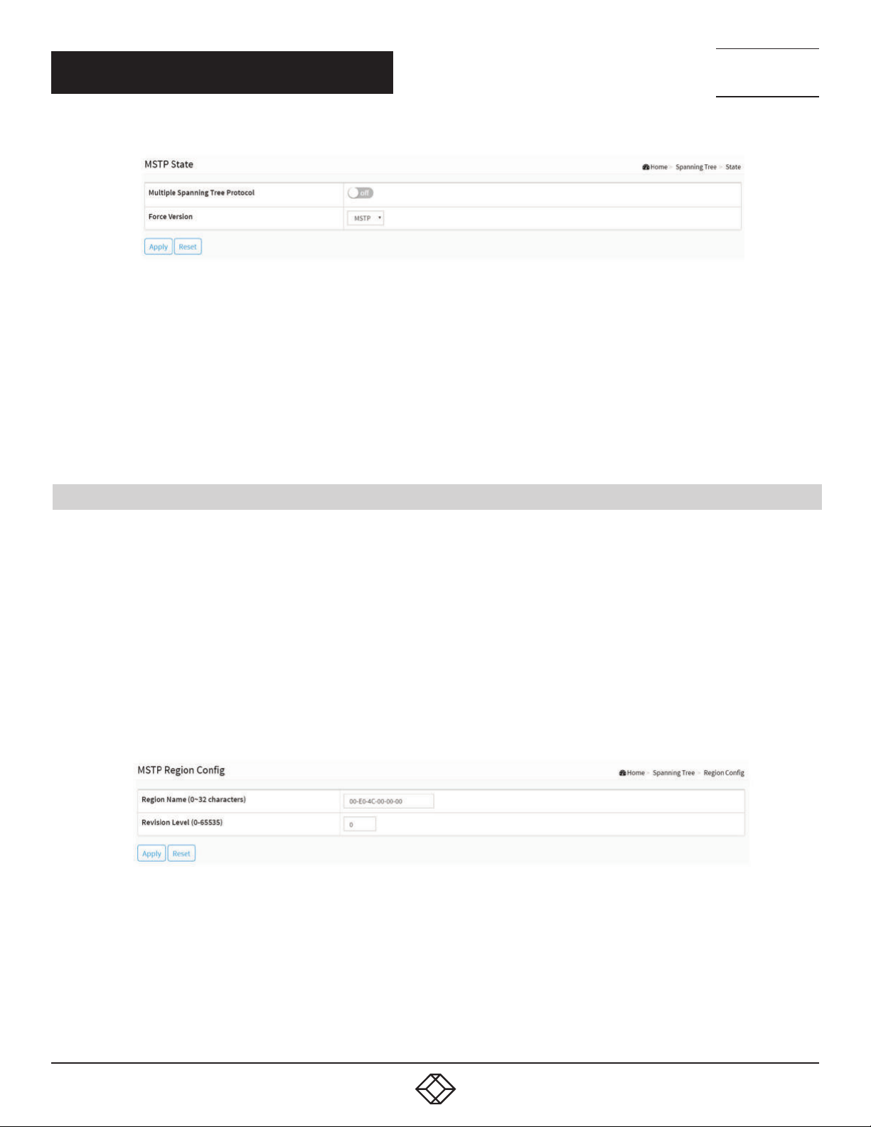
CHAPTER 7: SPANNING TREE
FIGURE 7-2. SPANNING TREE STATE
PARAMETER DESCRIPTION
Multiple Spanning Tree Protocol: You can select whether to enable spanning tree protocol or not.
Force Version: The STP protocol version setting. Valid values are STP, RSTP and MSTP.
Buttons
Apply: Click to save changes.
Reset: Click to undo any changes made locally and revert to previously saved values.
NEED HELP?
LEAV E TH E TEC H TO US
LIVE 24/7
TECHNICAL
SUPPORT
1. 87 7.8 77. 22 69
7.2 REGION CONFIG
This section describes how to configure the basic identification of a MSTP bridge. Bridges participating in a common MST region
must have the same Region Name and Revision Level.
WEB INTERFACE
To configure the Region Config in the web interface:
1. Click Spanning Tree and Region Config.
2. Specify the Region Name and Revision Level.
3. Click Apply to save the setting.
4. If you want to cancel the setting, then you need to click the Reset button. It will revert to previously saved values.
FIGURE 7-3. REGION CONFIGURATION
1. 8 7 7. 8 7 7. 2 2 6 9 BL ACK BO X.COM
81
Page 82
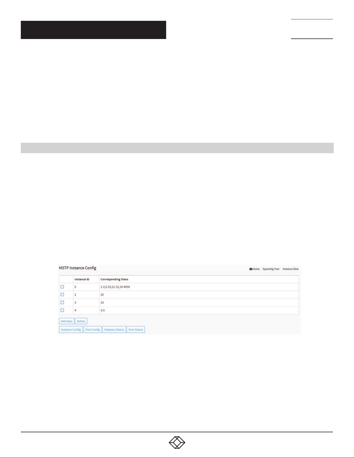
NEED HELP?
LEAV E TH E TEC H TO US
LIVE 24/7
CHAPTER 7: SPANNING TREE
PARAMETER DESCRIIPTION
Configuration Name: The name identifying the VLAN to MSTI mapping. Bridges must share the name and revision, as well as
the VLAN-to-MSTI mapping configuration in order to share spanning trees for MSTI’s (Intra-region). The name is, at most, 32
characters.
Configuration Revision: The revision of the MSTI configuration named above. This must be an integer between 0 and 65535.
Buttons
Apply: Click to save changes.
Reset: Click to undo any changes made locally and revert to previously saved values.
7.3 INSTANCE VIEW
This section provides an MST instance table that includes information(vlan membership of a MSTI ) of all spanning instances
provisioned in the particular MST region that the bridge belongs to. Through this table, additional MSTP configuration data can be
applied and MSTP status can be retrieved.
TECHNICAL
SUPPORT
1. 87 7.8 77. 22 69
WEB INTERFACE
To configure the MSTP Instance in the web interface:
1. Click Spanning Tree and Instance.
2. Click to add vlan.
3. Specify the Instance and Port.
4. Click Instance Status and Port Status to see the details.
5. If you want to cancel the setting, then you need to click Delete.
FIGURE 7-4. MSTP INSTANCE CONFIG
PARAMETER DESCRIPTION
Instance ID: Every spanning tree instance needs to have a unique instance ID within 0–4094. Instance 0 (CIST) always exists and
can not be deleted. Additional spanning instances (MSTIs) can be added or deleted. At least one vlan must be provisioned for an
MSTI to declare the need for the MSTI to exist.
Corresponding Vlans: 1-4094. Multiple vlans can belong to an MSTI. All vlans that are not provisioned through this will be
automatically assigned to Instance 0(CIST).
82
1. 8 7 7. 8 7 7. 2 2 6 9 BL ACK BO X.COM
Page 83
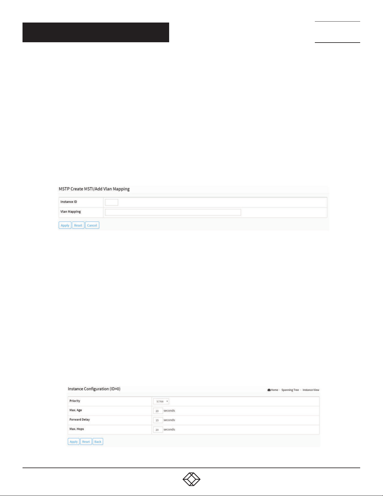
NEED HELP?
LEAV E TH E TEC H TO US
LIVE 24/7
CHAPTER 7: SPANNING TREE
Buttons
Add Vlan: Add an MSTI and provide its vlan members or modify vlan members for a specific MSTI, you can add up to 63 for a total
of 64.
Delete: Delete an MSTI.
Instance Config: Provision spanning tree performance parameters per instance.
Port Config: Provision spanning tree performance parameters per instance per port.
Instance Status: Show the status report of a particular spanning tree instance.
Port Status: Show the status report of all ports regarding a specific spanning tree instance.
Please refer to the following introduction:
Add Vlan:
TECHNICAL
SUPPORT
1. 87 7.8 77. 22 69
FIGURE 7-5. ADD VLAN
PARAMETER DESCRIIPTION
Instance ID: The Range is 1-4094.
Vlan Mapping: The list of VLANs mapped to the MSTI. The VLANs can be given as a single (xx, xx being between 1 and 4094) VLAN,
or a range (xx-yy), each of which must be separated with comma and/or space. A VLAN can only be mapped to one MSTI. An
unused MSTI should just be left empty. (I.e. not have any VLANs mapped to it.) Example: 2,5,20-40.
Buttons
Apply: Click to save changes.
Reset: Click to undo any changes made locally and revert to previously saved values.
Cancel: Click to undo any changes made locally and return to the Users.
Instance Config to Instance 0:
FIGURE 7-6. INSTANCE CONFIG TO INSTANCE 0
1. 8 7 7. 8 7 7. 2 2 6 9 BL ACK BO X.COM
83
Page 84
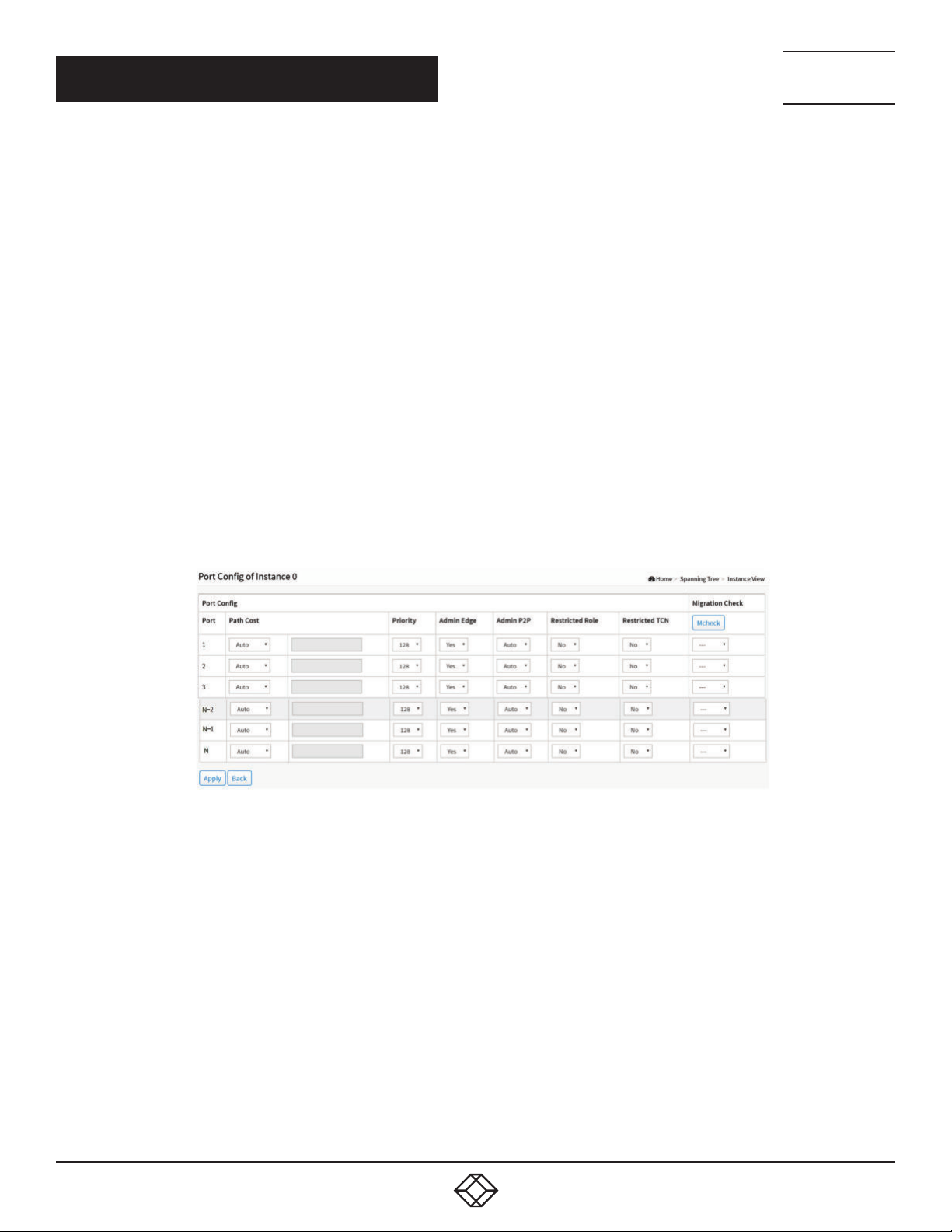
NEED HELP?
LEAV E TH E TEC H TO US
LIVE 24/7
CHAPTER 7: SPANNING TREE
PARAMETER DESCRIPTION
Priority: The priority parameter used in the CIST (Common and Internal Spanning Tree) connection.
0/4096/8192/12288/16384/20480/24576/28672/32768/36864/40960/45056/49152/53248/57344/61440
MAX. Age: 6-40 sec. The same definition as in the RSTP protocol.
Forward Delay: 4-30 sec. The same definition as in the RSTP protocol.
MAX. Hops: 6-40 sec. This is a new parameter for the multiple spanning tree protocol. It is used in the internal spanning tree
instances. “CIST Remaining Hops” or “MSTI Remaining Hops” in the Spanning tree protocol message would decrease by one when
the message is propagated to the neighboring bridge. If the Remaining Hops in a message is zero, the message (BPDU) would
be regarded as invalid. Max Hops is used to specify the initial value of the Remaining Hops for Regional Root Bridge (Either CIST
Regional Root or MSTI Regional Root).
Buttons
Apply: Click to save changes.
Reset: Click to undo any changes made locally and revert to previously saved values.
Back: Click to undo any changes made locally and return to the Users.
TECHNICAL
SUPPORT
1. 87 7.8 77. 22 69
Port Config to Instance 0:
FIGURE 7-7. PORT CONFIG TO INSTANCE 0
PARAMETER DESCRIPTION
Port: The logical port for the settings contained in the same row.
Path Cost: 1–200,000,000: The same definition as in the RSTP specification. But in MSTP, this parameter can be respectively
applied to ports of CIST and ports of any MSTI.
Priority: 0/16/32/48/64/80/96/112/128/144/160/176/192/208/224/240: The same definition as in the RSTP specification. But in
MSTP, this parameter can be respectively applied to ports of CIST and ports of any MSTI.
Admin Edge: Yes/No: The same definition as in the RSTP specification for the CIST ports.
Admin P2P: Auto/True/False: The same definition as in the RSTP specification for the CIST ports.
Restricted Role: Yes/No: If “Yes” causes the Port not to be selected as Root Port for the CIST or any MSTI, even if it has the best
spanning tree priority vector. Such a Port will be selected as an Alternate Port after the Root Port has been selected. This parameter
is “No” by default. If set, it can cause lack of spanning tree connectivity. It is set by a network administrator to prevent bridges
external to a core region of the network from influencing the spanning tree active topology, possibly because those bridges are not
under the full control of the administrator.
84
1. 8 7 7. 8 7 7. 2 2 6 9 BL ACK BO X.COM
Page 85
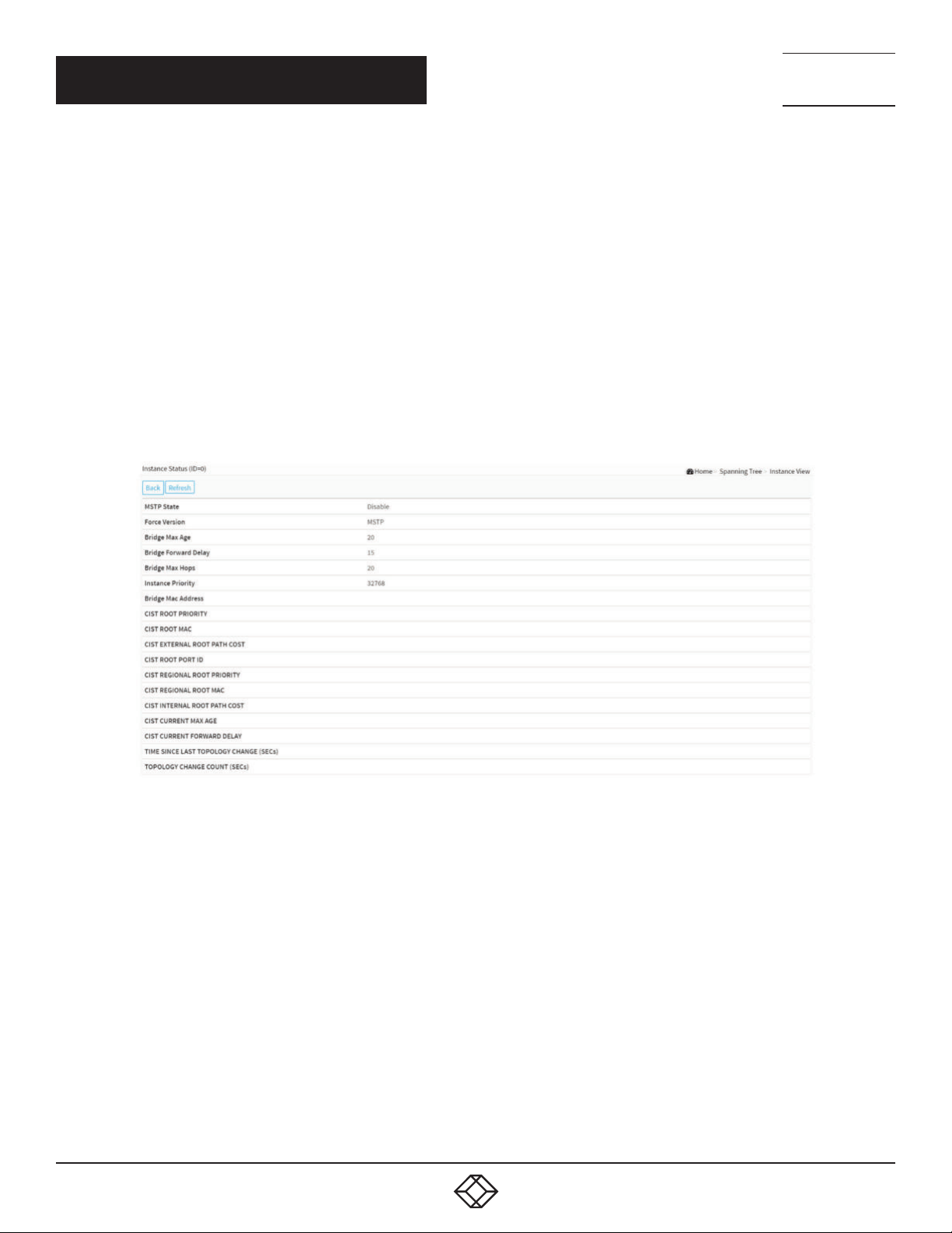
NEED HELP?
LEAV E TH E TEC H TO US
LIVE 24/7
CHAPTER 7: SPANNING TREE
TECHNICAL
SUPPORT
1. 87 7.8 77. 22 69
Restricted TCN: Yes/No: “Yes” causes the Port not to propagate received topology change notifications and topology changes to
other Ports. This parameter is “No” by default. If set it can cause temporary loss of connectivity after changes in a spanning tree’s
active topology as a result of persistent incorrectly learned station location information. It is set by a network administrator to prevent
bridges external to a core region of the network, causing address flushing in that region, possibly because those bridges are not under
the full the the network from influencing the spanning tree active topology, possibly because those bridges are not under the full
control of the administrator. Or the status of MAC operation for the attached LANs transitions frequently.
Mcheck: The same definition as in the RSTP specification for the CIST ports.
Buttons
Apply: Click to save changes.
Back: Click to undo any changes made locally and return to the Users.
Instance Status to Instance 0:
FIGURE 7-8. INSTANCE STATUS TO INSTANCE 0
PARAMETER DESCRIPTION
MSTP State: MSTP protocol is Enable or Disable.
Force Version: This shows the current spanning tree protocol version configured.
Bridge Max Age: This shows the Max Age setting of the bridge itself.
Bridge Forward Delay: This shows the Forward Delay setting of the bridge itself.
Bridge Max Hops: This shows the Max Hops setting of the bridge itself.
Instance Priority: Spanning tree priority value for a specific tree instance(CIST or MSTI).
Bridge Mac Address: The Mac Address of the bridge itself.
CIST ROOT PRIORITY: Spanning tree priority value of the CIST root bridge.
CIST ROOT MAC: Mac Address of the CIST root bridge.
CIST EXTERNAL ROOT PATH COST: Root path cost value from the point of view of the bridge’s MST region.
1. 8 7 7. 8 7 7. 2 2 6 9 BL ACK BO X.COM
85
Page 86
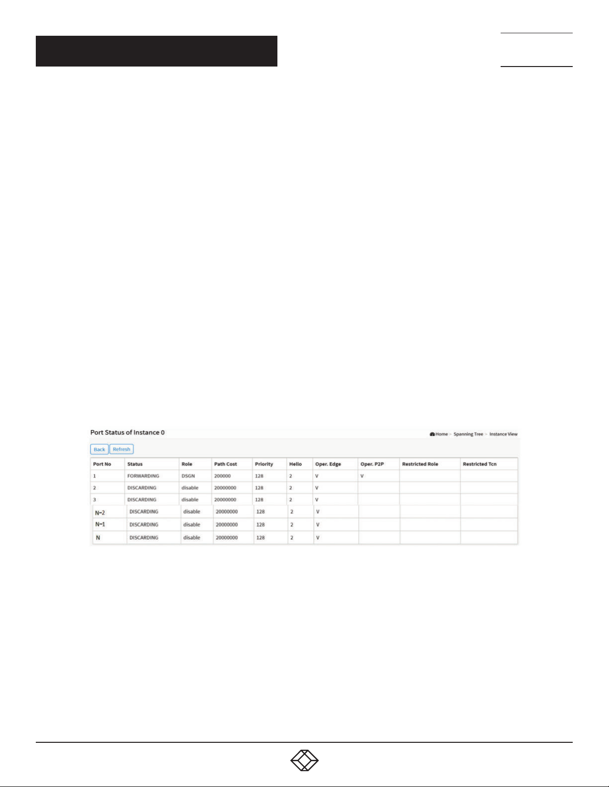
NEED HELP?
LEAV E TH E TEC H TO US
LIVE 24/7
CHAPTER 7: SPANNING TREE
CIST ROOT PORT ID: The port ID of the bridge’s root port. In MSTP, a peer port of a root port may reside in a different MST region or in
the same MST region. The first case indicates that the root port’s owner is the CIST regional root bridge.
CIST REGIONAL ROOT PRIORITY: Spanning tree priority value of the CIST regional root bridge. Note that CIST Regional Root bridge is
different from CIST Root bridge. One exception is that when a bridge belonging to an MST region happens to be the root bridge of the
CST (Common Spanning Tree). An MST Region in the CST can be regarded as a common RSTP bridge. The IST (Internal Spanning
Tree) and MSTIs are transparent to bridges outside this region.
CIST REGIONAL ROOT MAC: Mac Address of the CIST regional root bridge.
CIST INTERNAL ROOT PATH COST: Root path cost value from the point of view of the bridges inside the IST.
CIST CURRENT MAX AGE: Max Age of the CIST Root bridge.
CIST CURRENT FORWARD DELAY: Forward Delay of the CIST Root bridge.
TIME SINCE LAST TOPOLOGY CHANGE(SECs): Time Since Last Topology Change is the elapsed time in unit of seconds for a bunch
of “Topology Change and (or) Topology Change Notification receiving” to occur. When a new series of Topology Changes occur again,
this counter will be reset to 0.
TOPOLOGY CHANGE COUNT(SECs): The per spanning tree instance Topology Change Count expresses the time spent in unit of
seconds since the beginning of the Spanning Tree Topology Change to the end of the STP convergence. Once there is no topology
change occurring and no more topology change notification received, the Topology Change count will be reset to 0.
Buttons
Back: Click to undo any changes made locally and return to the Users.
Refresh: Click to refresh the page.
TECHNICAL
SUPPORT
1. 87 7.8 77. 22 69
Port Status to Instance 0:
FIGURE 7-9. PORT STATE TO INSTANCE 0
PARAMETER DESCRIPTION
Port No: The port number to which the configuration applies.
Status: The forwarding status. Same definition as of the RSTP specification. Possible values are “FORWARDING” , “LEARNING” ,
“DISCARDING”
Role: The role that a port plays in the spanning tree topology. Possible values are “disable” (disable port) , ”alternate” (alternate port) ,
“backup” (backup port) , “ROOT” (root port) , “DSGN” (designated port) , “MSTR” (master port). The last 3 are possible port roles for a
port to transit to FORWARDING state.
Path Cost: Display the currently resolved port path cost value for each port in a particular spanning tree instance.
Priority: Display the port priority value for each port in a particular spanning tree instance.
Hello: Per port Hello Time display. It takes the following form: Current Hello Time/Hello Time Setting
86
1. 8 7 7. 8 7 7. 2 2 6 9 BL ACK BO X.COM
Page 87

CHAPTER 7: SPANNING TREE
Oper. Edge: Whether or not a port is an Edge Port in reality.
Oper. P2P: Whether or not a port is a Point-to-Point Port in reality.
Restricted Role: Same as mentioned in “Port Config”
Restricted Tcn: Same as mentioned in “Port Config”
Buttons
Back: Click to undo any changes made locally and return to the Users.
Refresh: Click to refresh the page.
NEED HELP?
LEAV E TH E TEC H TO US
LIVE 24/7
TECHNICAL
SUPPORT
1. 87 7.8 77. 22 69
1. 8 7 7. 8 7 7. 2 2 6 9 BL ACK BO X.COM
87
Page 88
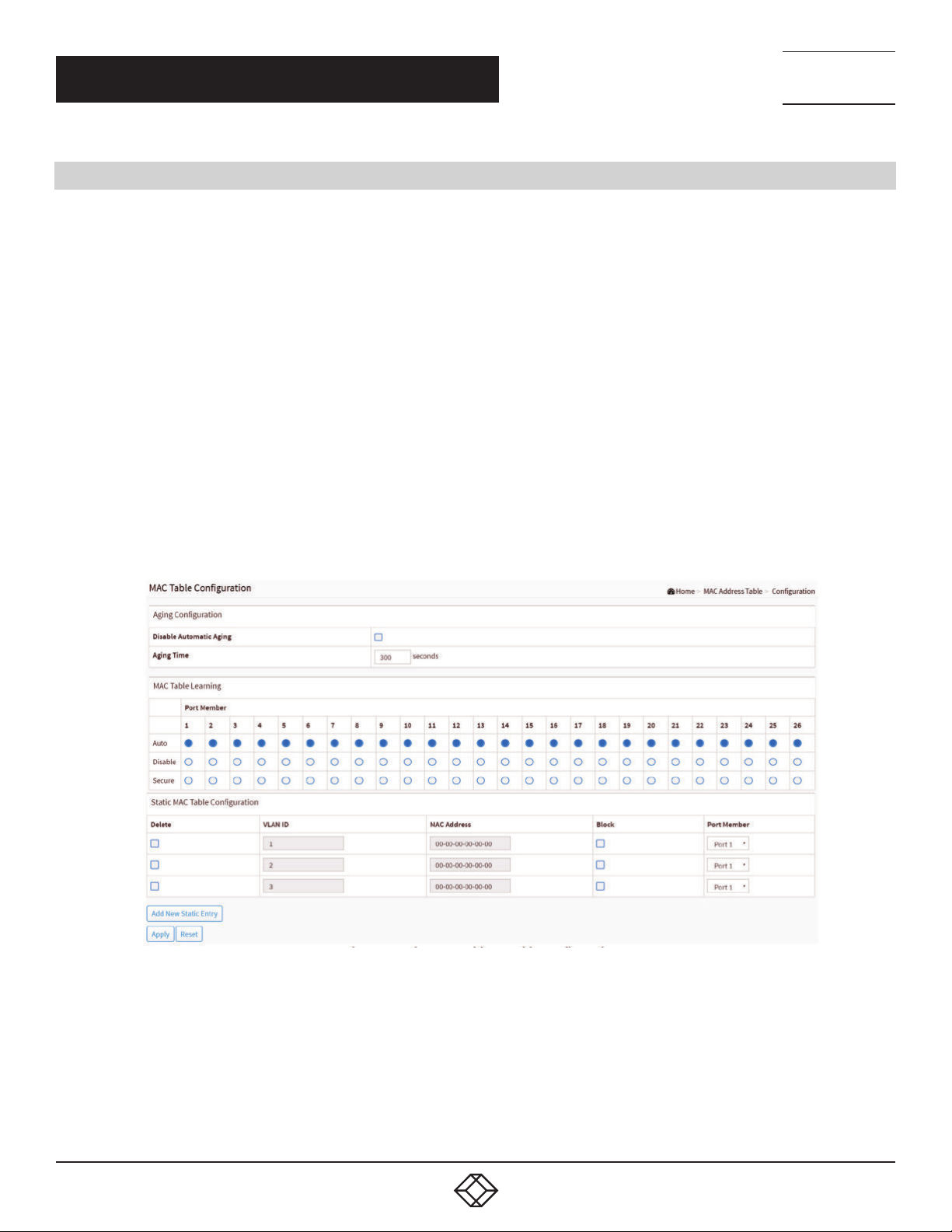
NEED HELP?
LEAV E TH E TEC H TO US
LIVE 24/7
CHAPTER 8: MAC ADDRESS TABLES
8.1 CONFIGURATION
Switching of frames is based upon the DMAC address contained in the frame. The switch builds up a table that maps MAC
addresses to switch ports for knowing which ports the frames should go to (based upon the DMAC address in the frame). This table
contains both static and dynamic entries. The static entries are configured by the network administrator if the administrator wants
to do a fixed mapping between the DMAC address and switch ports.
The frames also contain a MAC address (SMAC address) that shows the MAC address of the equipment sending the frame. The
SMAC address is used by the switch to automatically update the MAC table with these dynamic MAC addresses. Dynamic entries
are removed from the MAC table if no frame with the corresponding SMAC address have been seen after a configurable age time.
WEB INTERFACE
To configure MAC Address Table in the web interface:
1. Click MAC Address Tables and Configuration.
2. Specify the Disable Automatic Aging and Aging Time.
3. Specify the Port Members (Auto, Disable, Secure).
4. Add new Static entry, Specify the VLAN IP and Mac address, Port Members, Block.
5. Click Apply.
TECHNICAL
SUPPORT
1. 87 7.8 77. 22 69
PARAMETER DESCRIPTION
Aging Configuration: By default, dynamic entries are removed from the MAC table after 300 seconds. This removal is also called
aging.
Configure aging time by entering a value here in seconds; for example, Age time seconds.
The allowed range is 10 to 1000000 seconds.
88
FIGURE 8-1. MAC TABLE CONFIGURATION
1. 8 7 7. 8 7 7. 2 2 6 9 BL ACK BO X.COM
Page 89

NEED HELP?
LEAV E TH E TEC H TO US
LIVE 24/7
CHAPTER 8: MAC ADDRESS TABLES
TECHNICAL
SUPPORT
1. 87 7.8 77. 22 69
Disable the automatic aging of dynamic entries by checking the box next to Disable automatic aging.
MAC Table Learning: If the learning mode for a given port is grayed out, another module is in control of the mode, so it cannot be
changed by the user. An example of such a module is the MAC-Based Authentication under 802.1X. Each port can do learning
based upon the following settings.
Learning: Learning is done automatically as soon as a frame with unknown SMAC is received.
Disable: No learning is done.
Secure: Only static MAC entries are learned, all other frames are dropped.
NOTE: Make sure that the link used for managing the switch is added to the Static Mac Table before changing to secure learning
mode, otherwise the management link is lost and can only be restored by using another non-secure port or by connecting to the
switch via the serial interface.
Static MAC Table Configuration
The static entries in the MAC table are shown in this table. The static MAC table can contain 128 entries. The maximum of 128
entries is for the whole stack, and not per switch.
Delete: Check to delete the entry. It will be deleted during the next save.
VLAN ID: The VLAN ID of the entry.
MAC Address: The MAC address of the entry.
Block: Click Block if you want block this mac address.
Port Members: Checkmarks indicate which ports are members of the entry. Check or uncheck as needed to modify the entry.
Buttons
Adding a New Static Entry: Click to add a new entry to the static MAC table. Specify the VLAN ID, MAC address, and port members
for the new entry. Click “Apply”.
Apply: Click to save changes.
Reset: Click to undo any changes made locally and revert to previously saved values.
8.2 INFORMATION
Entries in the MAC Table are shown on this page. The MAC Table contains up to 8192 entries, and is sorted first by VLAN ID, then by
MAC address.
WEB INTERFACE
To Display MAC Address Table in the web interface:
1. Click MAC Address Table and Information.
2. Display MAC Address Table.
1. 8 7 7. 8 7 7. 2 2 6 9 BL ACK BO X.COM
89
Page 90
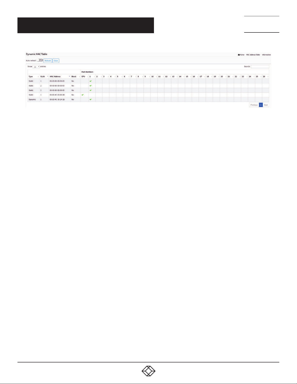
NEED HELP?
LEAV E TH E TEC H TO US
LIVE 24/7
CHAPTER 8: MAC ADDRESS TABLES
FIGURE 8-2. MAC ADDRESS TABLE INFORMATION
PARAMETER DESCRIPTION
Navigating the MAC Table
Each page shows up to 999 entries from the MAC table, default is 10, selected through the “entries per page” input field. When first
visited, the web page will show the first 10 entries from the beginning of the MAC Table. The first displayed will be the one with the
lowest VLAN ID and the lowest MAC address found in the MAC Table.
Type: Indicates whether the entry is a static or a dynamic entry, 802.1x, DMS.
VLAN: The VLAN ID of the entry.
MAC address: The MAC address of the entry.
Block: Whether the mac address is blocked or not.
Port Members: The ports that are members of the entry.
Buttons
Auto-refresh: Check this box to refresh the page automatically. Automatic refresh occurs every 3 seconds.
Refresh: Click to refresh the page.
Clear: Click to clear the page.
Next: Updates the mac address entries, turns to the next page.
Previous: Updates the mac address entries, turns to the previous page.
NOTE:
00-40-C7-73-01-29: your switch MAC address (for IPv4)
33-33-00-00-00-01: Destination MAC (for IPv6 Router Advertisement) (reference IPv6 RA.JPG)
33-33-00-00-00-02: Destination MAC (for IPv6 Router Solicitation) (reference IPv6 RS.JPG)
33-33-FF-73-01-29: Destination MAC (for IPv6 Neighbor Solicitation) (reference IPv6 DAD.JPG)
33-33-FF-A8-01-01: your switch MAC address (for IPv6 global IP)
FF-FF-FF-FF-FF-FF: for Broadcast.
TECHNICAL
SUPPORT
1. 87 7.8 77. 22 69
90
1. 8 7 7. 8 7 7. 2 2 6 9 BL ACK BO X.COM
Page 91

NEED HELP?
LEAV E TH E TEC H TO US
LIVE 24/7
CHAPTER 9: MULTICAST
TECHNICAL
SUPPORT
1. 87 7.8 77. 22 69
9.1 IGMP SNOOPING
IGMP Snooping is used to establish multicast groups to forward multicasts packet to the member ports without wasting bandwidth
while IP multicast packets are running over the network. This is because a switch that does not support IGMP or IGMP Snooping
cannot tell the multicast packet from a broadcast packet, so it can only treat them all as broadcast packets. Without IGMP
Snooping, the multicast packet forwarding function is the same as for a broadcast packet.
A switch supporting IGMP Snooping with the functions of query, report and leave, a type of packet exchanged between IP Multicast
Router/Switch and IP Multicast Host, can update the information of the Multicast table when a member (port) joins or leaves an IP
Multicast Destination Address. With this function, once a switch receives an IP multicast packet, it will forward the packet to the
members who joined in a specified IP multicast group before.
The packets will be discarded by the IGMP Snooping if the user transmits multicast packets to the multicast group that had not
been built up in advance. IGMP mode enables the switch to issue the IGMP function when you enable IGMP proxy or snooping
on the switch that connects to a router closer to the root of the tree. This interface is the upstream interface. The router on the
upstream interface should be running IGMP.
9.1.1 BASIC CONFIGURATION
This section describes how to set the basic IGMP snooping on the switch that connects to a router closer to the root of the tree.
This interface is the upstream interface. The router on the upstream interface should be running IGMP.
WEB INTERFACE
To configure the IGMP Snooping parameters in the web interface:
1. Click Multicast, IGMP Snooping and Basic Configuration.
2. Select enable or disable the Global configuration.
3. Select the port to become a Router Port or enable/disable the Fast Leave function.
4. Scroll to set the Throtting and Profile.
5. Click Apply to save the setting.
6. If you want to cancel the setting, then you need to click the Reset button. It will revert to previously saved values.
1. 8 7 7. 8 7 7. 2 2 6 9 BL ACK BO X.COM
91
Page 92
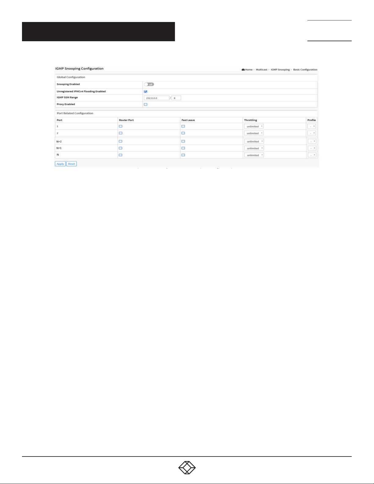
CHAPTER 9: MULTICAST
FIGURE 9-1. IGMP SNOOPING CONFIGURATION
NEED HELP?
LEAV E TH E TEC H TO US
LIVE 24/7
TECHNICAL
SUPPORT
1. 87 7.8 77. 22 69
PARAMETER DESCRIPTION
Global Configuration
Snooping Enabled: Enable Global IGMP Snooping.
Unregistered IPMCv4 Flooding enabled: Enable unregistered IPMCv4 traffic flooding. Unregistered IPMCv4 traffic is so-called
unknown multicast. After selected, the unregistered multicast stream will be forwarded like normal packets. Once you un-select it, the
stream will be discarded.
IGMP SSM Range: SSM (Source-Specific Multicast) Range allows the SSM-aware hosts and routers to run the SSM service model for
the groups in the address range. Format: (IP address/ sub mask).
Proxy Enabled: Enable IGMP Proxy. This feature can be used to avoid forwarding unnecessary join and leave messages to the router
side.
Port Related Configuration
Port: This shows the physical Port index of switch.
Router Port: Specify which ports act as router ports. A router port is a port on the Ethernet switch that leads towards the Layer 3
multicast device or IGMP querier. If an aggregation member port is selected as a router port, the whole aggregation will act as a router
port.
Fast Leave: Enable fast leave on the port.
Throttling: Enable to limit the number of multicast groups to which a switch port can belong.
Profile: You can select the profile to edit in Multicast Filtering Profile.
Buttons
Apply: Click to save changes.
Reset: Click to undo any changes made locally and revert to previously saved values.
92
1. 8 7 7. 8 7 7. 2 2 6 9 BL ACK BO X.COM
Page 93
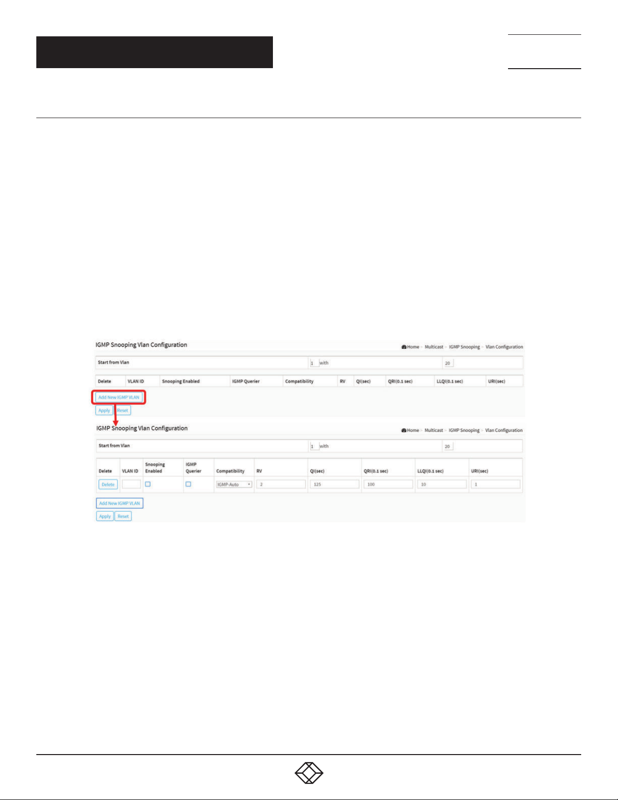
NEED HELP?
LEAV E TH E TEC H TO US
LIVE 24/7
CHAPTER 9: MULTICAST
TECHNICAL
SUPPORT
1. 87 7.8 77. 22 69
9.1.2 VLAN CONFIGURATION
This section describes the VLAN configuration setting process integrated with the IGMP Snooping function. Each setting page
shows up to 99 entries from the VLAN table, default is 20, selected through the “entries per page” input field. When first visited, the
web page will show the first 20 entries from the beginning of the VLAN Table. The first displayed will be the one with the lowest VLAN
ID found in the VLAN Table. The “VLAN” input fields allow the user to select the starting point in the VLAN Table. Clicking the button
will update the displayed table starting from that or the next closest VLAN Table match.
WEB INTERFACE
To configure the IGMP Snooping VLAN Configuration in the web interface:
1. Click Multicast, IGMP Snooping and VLAN Configuration.
2. Click to add new IGMP VLAN.
3. Click Apply to save the setting
4. If you want to cancel the setting, then you need to click the Reset button. It will revert to previously saved values.
FIGURE 9-2. IGMP SNOOPING VLAN CONFIGURATION
PARAMETER DESCRIPTION
Start from Vlan: Refreshes the displayed table starting from the “VLAN” input fields.
Delete: Check to delete the entry. The designated entry will be deleted during the next save.
VLAN ID: Displays the VLAN ID of the entry.
Snooping Enabled: Enable the per-VLAN IGMP Snooping. Up to 32 VLANs can be selected.
IGMP Querier: Enable to join IGMP Querier election in the VLAN. Disable to act as an IGMP Non-Querier.
Compatibility: Compatibility is maintained by hosts and routers taking appropriate actions depending on the versions of IGMP
operating on hosts and routers within a network. The allowed selection is IGMP-Auto, Forced IGMPv1, Forced IGMPv2, Forced
IGMPv3; the default compatibility value is IGMP-Auto.
Rv: Robustness Variable. The Robustness Variable allows tuning for the expected packet loss on a network. The allowed range is 1 to
255; the default robustness variable value is 2.
1. 8 7 7. 8 7 7. 2 2 6 9 BL ACK BO X.COM
93
Page 94
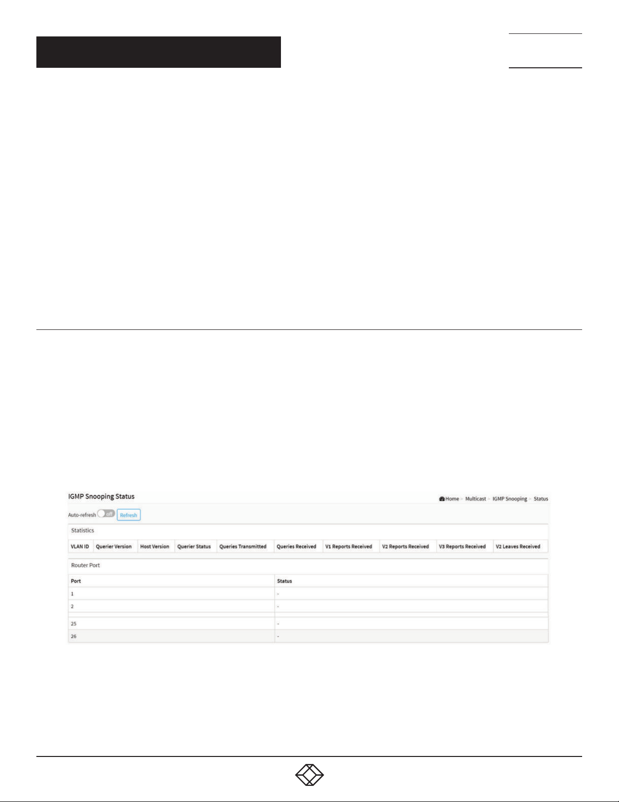
NEED HELP?
LEAV E TH E TEC H TO US
LIVE 24/7
CHAPTER 9: MULTICAST
QI (sec): Query Interval. The Query Interval is the interval between General Queries sent by the Querier. The allowed range is 1 to 31744
seconds; the default query interval is 125 seconds.
QRI (0.1 sec): Query Response Interval. The Max Response Time used to calculate the Max Resp Code inserted into the periodic
General Queries. The allowed range is 0 to 31744 in tenths of seconds; the default query response interval is 100 in tenths of seconds
(10 seconds).
LLQI (0.1 sec): Last Member Query Interval. The Last Member Query Time is the time value represented by the Last Member Query
Interval, multiplied by the Last Member Query Count. The allowed range is 0 to 31744 in tenths of seconds; the default last member
query interval is 10 in tenths of seconds (1 second).
URI (sec): Unsolicited Report Interval. The Unsolicited Report Interval is the time between repetitions of a host’s initial report of
membership in a group. The allowed range is 0 to 31744 seconds, default unsolicited report interval is 1 second.
Buttons
Apply: Click to save changes.
Reset: Click to undo any changes made locally and revert to previously saved values.
TECHNICAL
SUPPORT
1. 87 7.8 77. 22 69
9.1.3 STATUS
After you complete the IGMP Snooping configuration, you can set the switch to display the IGMP Snooping Status. The section
explains how to display the IGMP Snooping detail status.
WEB INTERFACE
To display the IGMP Snooping status in the web interface:
1. Click Multicast, IGMP Snooping and Status.
2. If you want to auto-refresh the information, then you need to evoke the “Auto-refresh”.
3. Click “Refresh” to refresh the IGMP Snooping Status.
94
FIGURE 9-3. IGMP SNOOPING STATUS
1. 8 7 7. 8 7 7. 2 2 6 9 BL ACK BO X.COM
Page 95

NEED HELP?
LEAV E TH E TEC H TO US
LIVE 24/7
CHAPTER 9: MULTICAST
TECHNICAL
SUPPORT
1. 87 7.8 77. 22 69
PARAMETER DESCRIPTION
Statistic
VLAN ID: The VLAN ID of the entry.
Querier Version: Currently working Querier Version.
Host Version: Currently working Host Version.
Querier Status: Shows the Querier status is “ACTIVE” or “IDLE”. “DISABLE” denotes the specific interface is administratively disabled.
Queries Transmitted: The number of Transmitted Queries.
Queries Received: The number of Received Queries.
V1 Reports Received: The number of Received V1 Reports.
V2 Reports Received: The number of Received V2 Reports.
V3 Reports Received: The number of Received V3 Reports.
V2 Leaves Received: The number of Received V2 Leaves.
Router Port
Display the ports that act as router ports. A router port is a port on the Ethernet switch that leads towards the Layer 3 multicast
device or IGMP querier. Static denotes the specific port is configured to be a router port. Dynamic denotes the specific port is
learned to be a router port. Both denote the specific port is configured and learned to be a router port.
Port: Switch port number.
Status: Indicates whether a specific port is a router port or not.
Buttons
Auto-refresh: Check this box to refresh the page automatically. Automatic refresh occurs every 3 seconds.
Refresh: Click to refresh the page immediately.
9.1.4 GROUP INFORMATION
After you set the IGMP Snooping function, you can set the switch to display the IGMP Snooping Group Information. Entries in the
IGMP Group Table are shown on this page. The IGMP Group Table is sorted first by VLAN ID, and then by group. This will use the
last entry of the currently displayed table as a basis for the next lookup. When the end is reached the text “No more entries” is
shown in the displayed table. Use the button to start over.
WEB INTERFACE
To display the IGMP Snooping Group Information in the web interface:
1. Click Multicast, IGMP Snooping and Group Information.
2. Specify how many entries to show in one page.
3. If you want to auto-refresh the information, then you need to select “Auto-refresh”.
4. Click “Refresh” to refresh an entry of the IGMP Snooping Groups Information.
5. Click Previous/next to change the page.
1. 8 7 7. 8 7 7. 2 2 6 9 BL ACK BO X.COM
95
Page 96
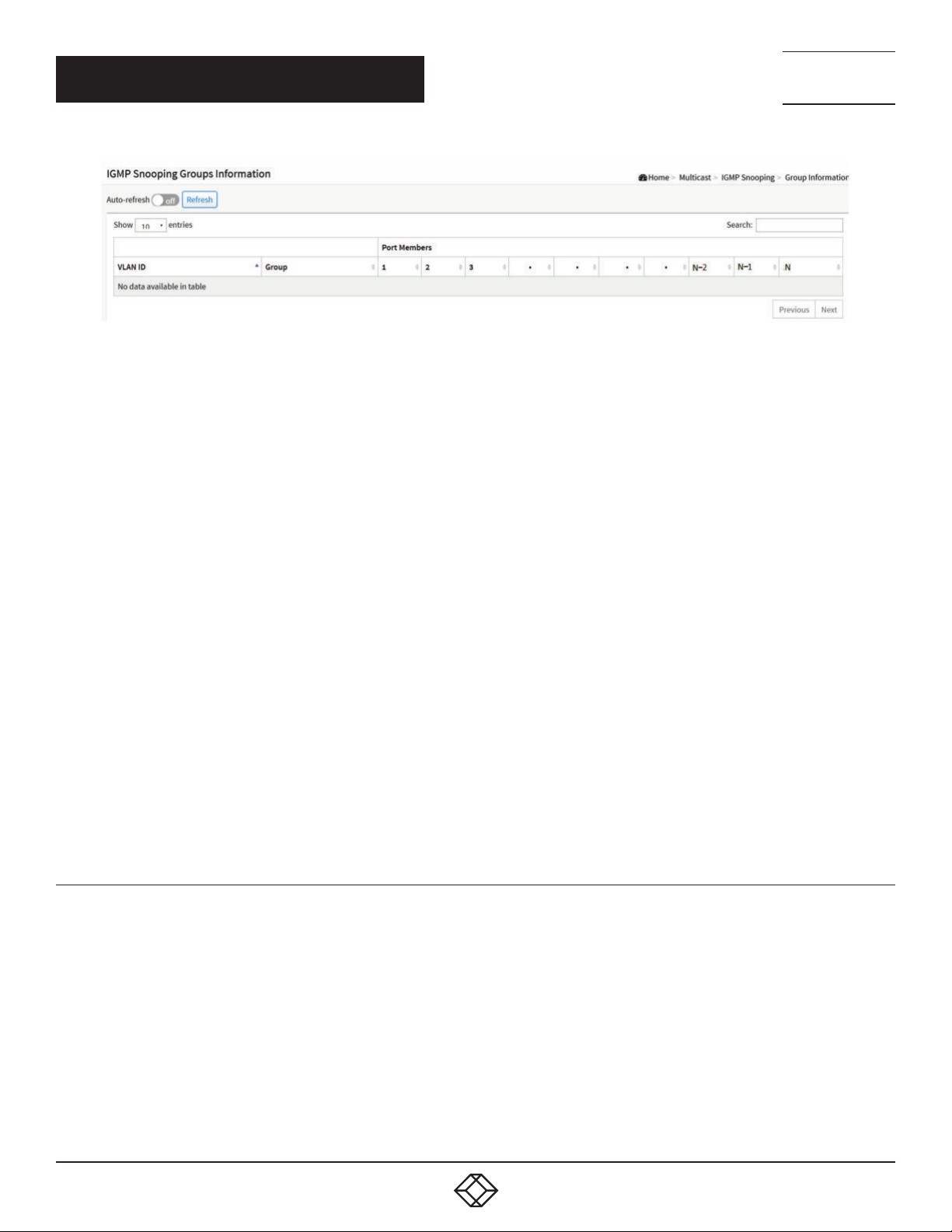
NEED HELP?
LEAV E TH E TEC H TO US
LIVE 24/7
CHAPTER 9: MULTICAST
FIGURE 9-4. IGMP SNOOPING GROUPS INFORMATION
PARAMETER DESCRIPTION
Navigating the IGMP Group Table
Each page shows the number of entries from the IGMP Group table, default is 10, selected through the “entries per page” input field.
When first visited, the web page will show the first 10 entries from the beginning of the IGMP Group Table.
The “Search” input fields allow the user to select the starting point in the IGMP Group Table. It will update the displayed table starting
from that or the next closest IGMP Group Table match.
This will use the last entry of the currently displayed table as a basis for the next lookup. When the end is reached, the text “No more
entries” is shown in the displayed table.
Search: You can search for the information that you want to see.
Show entries: You can choose how many items you want to show up.
VLAN ID: VLAN ID of the group.
Groups: Group address of the group displayed.
Port Members: Ports under this group.
Buttons
Auto-refresh: Check this box to refresh the page automatically. Automatic refresh occurs every 3 seconds.
Refresh: Click to refresh the page immediately.
Next: Updates the group information entries, turns to the next page.
Previous: Updates the group information entries, turns to the previous page.
TECHNICAL
SUPPORT
1. 87 7.8 77. 22 69
9.1.5 IGMP SFM INFORMATION
Entries in the IGMP SFM Information Table are shown on this page. The IGMP SFM (Source-Filtered Multicast) Information Table
also contains the SSM (Source-Specific Multicast) information. This table is sorted first by VLAN ID, then by group, and then by Port.
Different source addresses that belong to the same group are treated as single entry.
WEB INTERFACE
To display the IGMP SFM Information in the web interface:
1. Click Multicast, IGMP Snooping and IGMP SFM Information
2. If you want to auto-refresh the information, then you need to select “Auto-refresh”.
3. Click “Refresh” to refresh an entry of the IGMP Snooping Groups Information.
96
1. 8 7 7. 8 7 7. 2 2 6 9 BL ACK BO X.COM
Page 97
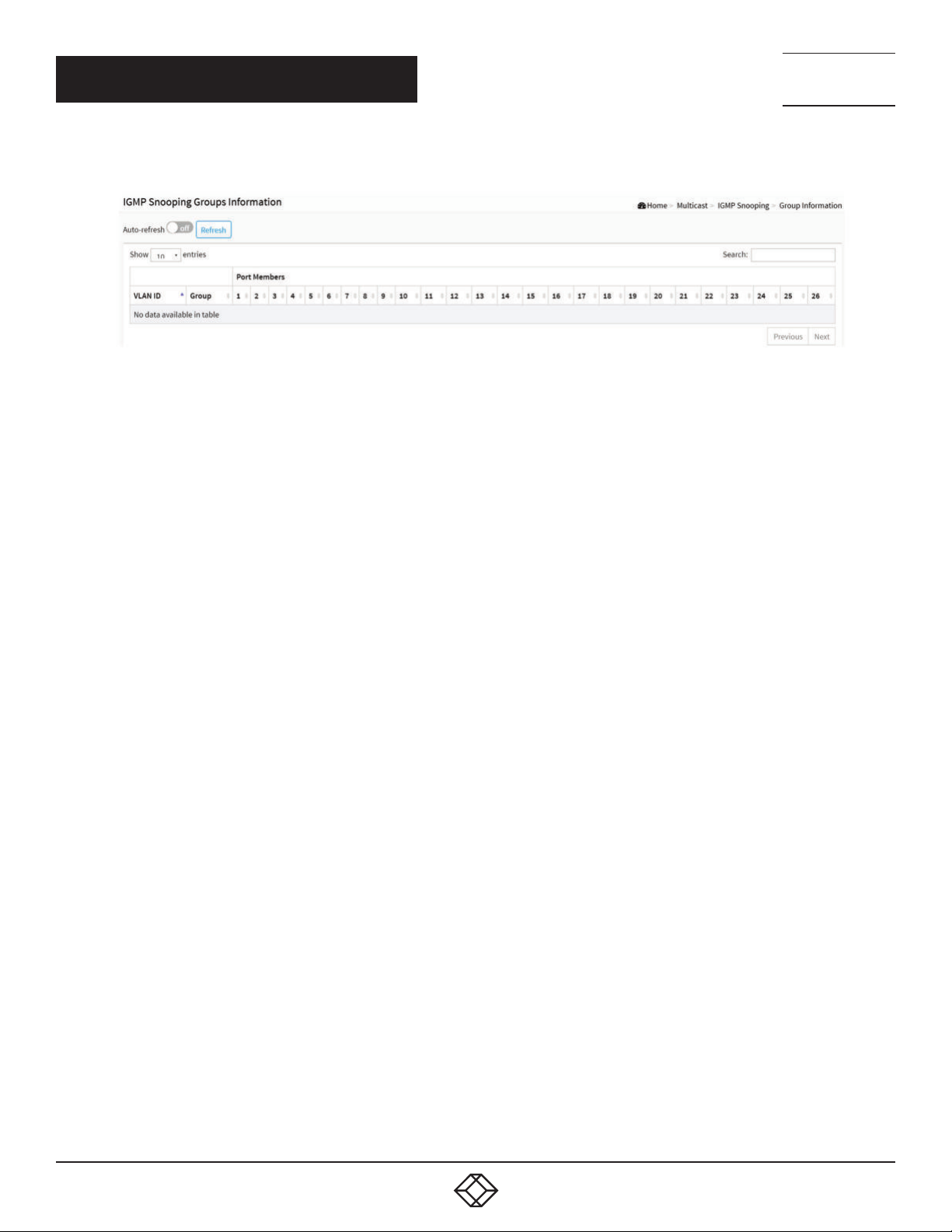
NEED HELP?
LEAV E TH E TEC H TO US
LIVE 24/7
CHAPTER 9: MULTICAST
TECHNICAL
SUPPORT
1. 87 7.8 77. 22 69
4. Click Previous/next to change the page.
FIGURE 9-5. IGMP SFM INFORMATION
PARAMETER DESCRIPTION
Navigating the IGMP SFM Information Table
Each page shows the entries from the IGMP SFM Information table, default is 10, selected through the “entries per page” input field.
When first visited, the web page will show the first 10 entries from the beginning of the IGMP SFM Information Table.
The “Search” input fields allow the user to select the starting point in the IGMP SFM Information Table. It will update the displayed
table starting from that or the next closest IGMP SFM Information Table match.
This will use the last entry of the currently displayed table as a basis for the next lookup. When the end is reached, the text “No
more entries” is shown in the displayed table.
Search: You can search for the information that you want to see.
Show entries: You can choose how many items you want to show up.
VLAN ID: VLAN ID of the group.
Group: Group address of the group displayed.
Port: Switch port number.
Mode: Indicates the filtering mode maintained per (VLAN ID, port number, Group Address) basis. It can be either Include or Exclude.
Source Address: IP Address of the source. Currently, system limits the total number of IP source addresses for filtering to 128.
Type: Indicates the Type. It can be either Allow or Deny.
Buttons
Auto-refresh: Check this box to refresh the page automatically. Automatic refresh occurs every 3 seconds.
Refresh: Click to refresh the page immediately.
Next: Updates the group information entries, turns to the next page.
Previous: Updates the group information entries, turns to the previous page.
1. 8 7 7. 8 7 7. 2 2 6 9 BL ACK BO X.COM
97
Page 98
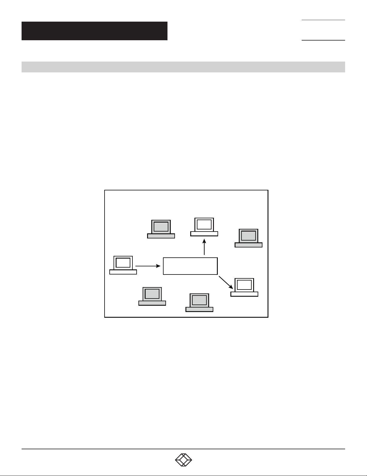
NEED HELP?
LEAV E TH E TEC H TO US
LIVE 24/7
CHAPTER 9: MULTICAST
TECHNICAL
SUPPORT
1. 87 7.8 77. 22 69
9.2 MLD SNOOPING
A network node that acts as a source of IPv6 multicast traffic is only an indirect participant in MLD snooping—it just provides
multicast traffic, and MLD doesn’t interact with it.
NOTE: In an application like desktop conferencing, a network node may act as both a source and an MLD host; but MLD interacts
with that node only in its role as an MLD host.
A source node creates multicast traffic by sending packets to a multicast address. In IPv6, addresses with the first eight bits set
(that is, “FF” as the first two characters of the address) are multicast addresses, and any node that listens to such an address
will receive the traffic sent to that address. Application software running on the source and destination systems cooperates to
determine what multicast address to use.
NOTE: This is a function of the application software, not of MLD.
When MLD snooping is enabled on a VLAN, the switch acts to minimize unnecessary multicast traffic. If the switch receives
multicast traffic destined for a given multicast address, it forwards that traffic only to ports on the VLAN that have MLD hosts for
that address. It drops that traffic for ports on the VLAN that have no MLD hosts.
MLD SNOOPING ENABLED
SWITCH
SOURCE
FIGURE 9-6.MLD SNOOPING ENABLE
LISTENER
(MLD HOST)
LISTENER
(MLD HOST
)
98
1. 8 7 7. 8 7 7. 2 2 6 9 BL ACK BO X.COM
Page 99
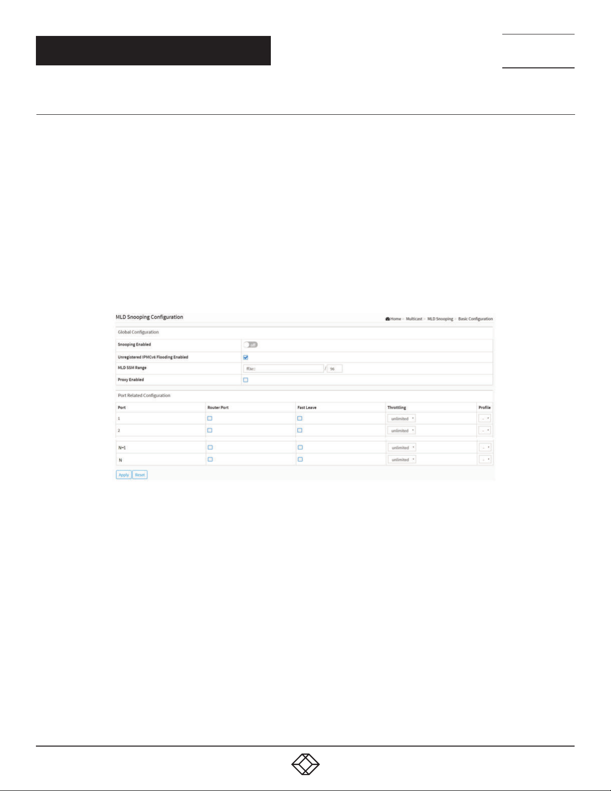
CHAPTER 9: MULTICAST
9.2.1 BASIC CONFIGURATION
This section explains how to configure the MLD Snooping basic configuration and the parameters.
WEB INTERFACE
To configure the MLD Snooping Configuration in the web interface:
1. Click Multicast, MLD Snooping and Basic Configuration.
2. Enable or disable the Global configuration parameters.
3. Select the port to join Router port and Fast Leave.
4. Scroll to select the Throtting mode with unlimited or 1 to 10.
5. Click save to save the setting.
6. If you want to cancel the setting, then you need to click the Reset button. It will revert to previously saved values.
NEED HELP?
LEAV E TH E TEC H TO US
LIVE 24/7
TECHNICAL
SUPPORT
1. 87 7.8 77. 22 69
FIGURE 9-7. MLD SNOOPING BASIC CONFIGURATION
PARAMETER DESCRIPTION
Global Configuration
Snooping Enabled: Enable Global MLD Snooping.
Unregistered IPMCv6 Flooding enabled: Enable unregistered IPMCv6 traffic flooding.
The flooding control takes effect only when MLD Snooping is enabled.
When MLD Snooping is disabled, unregistered IPMCv6 traffic flooding is always active in spite of this setting.
MLD SSM Range: SSM (Source-Specific Multicast) Range allows the SSM-aware hosts and routers to run the SSM service model for
the groups in the address (Using IPv6 Address) range.
Proxy Enabled: Enable MLD Proxy. This feature can be used to avoid forwarding unnecessary join and leave messages to the router
side.
Port Related Configuration
Router Port: Specify which ports act as router ports. A router port is a port on the Ethernet switch that leads towards the Layer 3
multicast device or MLD querier. If an aggregation member port is selected as a router port, the whole aggregation will act as a router
port.
1. 8 7 7. 8 7 7. 2 2 6 9 BL ACK BO X.COM
99
Page 100
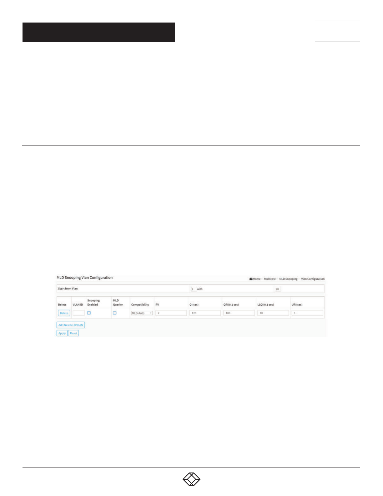
NEED HELP?
LEAV E TH E TEC H TO US
LIVE 24/7
CHAPTER 9: MULTICAST
Fast Leave: Select to enable fast leave on the port.
Throttling: Enable to limit the number of multicast groups to which a switch port can belong.
Profile: You can select profile when you edit in Multicast Filtering Profile.
Buttons
Apply: Click to save changes.
Reset: Click to undo any changes made locally and revert to previously saved values.
TECHNICAL
SUPPORT
1. 87 7.8 77. 22 69
9.2.2 VLAN CONFIGURATION
When MLD snooping is enabled on a VLAN, the switch acts to minimize unnecessary multicast traffic. If the switch receives
multicast traffic destined for a given multicast address, it forwards that traffic only to ports on the VLAN that have MLD hosts for that
address. It drops that traffic for ports on the VLAN that have no MLD hosts.
The switch will use the last entry of the currently displayed entry as a basis for the next lookup. When the end is reached, the text “No
more entries” is shown in the displayed table. Use the button to start over.
WEB INTERFACE
To configure the MLD Snooping VLAN Configuration in the web interface:
1. Click Multicast, MLD Snooping and VLAN Configuration.
2. Click Add New MLD VLAN.
3. Specify the VLAN ID with entries per page.
FIGURE 9-8. MLD SNOOPING VLAN CONFIGURATION
PARAMETER DESCRIPTION
Delete: Check to delete the entry. The designated entry will be deleted during the next save.
VLAN ID: It displays the VLAN ID of the entry.
Snooping Enabled: Enable the per-VLAN IGMP Snooping. Up to 32 VLANs can be selected.
MLD Querier: Enable to join IGMP Querier election in the VLAN. Disable to act as an IGMP Non-Querier.
Compatibility: Compatibility is maintained by hosts and routers taking appropriate actions depending on the versions of IGMP
operating on hosts and routers within a network. The allowed selection is IGMP-Auto, Forced IGMPv1, Forced IGMPv2; the default
compatibility value is IGMP-Auto.
RV: Robustness Variable. The Robustness Variable allows tuning for the expected packet loss on a network. The allowed range is 1 to
255; the default robustness variable value is 2.
100
1. 8 7 7. 8 7 7. 2 2 6 9 BL ACK BO X.COM
 Loading...