

Page 1
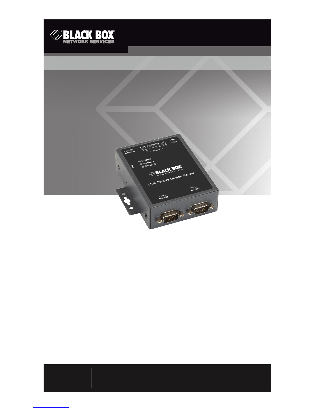
Quick Start Guide
1102 Secure Device Server
Order toll-free in the U.S.: Call 877-877-BBOX (outside U.S. call 724-746-5500)
FREE technical support 24 hours a day, 7 days a week: Call 724-746-5500 or fax
724-746-0746 • Mailing address: Black Box Corporation, 1000 Park Drive, Lawrence,
PA 15055-1018 • Web site: www.blackbox.com • E-mail: [email protected]
Customer
Support
Information
May 2010
LES1102A
About This Guide
This Quick Start Guide walks you through installation, configuration, and local
operation. For more details, refer to the user manual on the CD-ROM.
Trademarks Used in this Manual
Black Box and the Double Diamond logo are registered trademarks of
BB Technologies, Inc.
Linux is a registered trademark of Linus Torvalds.
Nagios is a registered trademark of Nagios Enterprises.
Any other trademarks mentioned in this manual are acknowledged to be
the property of the trademark owners.
Page 2

Page 2
724-746-5500 | blackbox.com
1102 Secure Device Server Quick Start Guide
Step 1: Check kit contents.
• 1102 Secure Device Server
• This printed quick start guide
• CD-ROM containing a user’s manual in PDF format
• (2) UTP cables
• (1) DB9F-RJ-45 adapter straight-pinned
• (1) DB9F-RJ-45 adapter crossover-pinned
• Universal input 12-VDC power pack
Step 2: Connect the hardware.
• Attach the four rubber feet to the base (unless the LES1102A will be DIN rail
mounted).
• Plug the power pack into the AC power receptacle and connect the DC
power cable to the 9-12 VDC power socket on the LES1102A. Or the
LES1102A can be powered from any +9 to +48 VDC power source. Connect
these power lines to the IN-GND and IN-VIN+ screw jacks.
• Connect your serial devices to the two serial ports.
- Port 1 is a dedicated RS-232 port, and the pinout is standard DB9 male.
- Port 2 can be software configured to be either an RS-232 port (using the
Port 2 DB9 connector) or an RS-422/RS-485 port (using the TX+/TX- and
RX+/RX- pairs on the terminal block.
Terminal block pinouts: 1 2 3 4 5 6 7 8
+VDC in GND RX+ RX- TX+ TX- +3.3 VDC out GND
Page 3
Page 3
724-746-5500 | blackbox.com
1102 Secure Device Server Quick Start Guide
Step 3: Set up the console server.
The default console server IP address is 192.168.0.1 (subnet mask
255.255.255.0).
With a Web browser on any computer that is connected through the LAN to
the serial device server:
• Enter https://192.168.0.1 into the address bar.
NOTE: The LAN-connected computer must have an IP address in the same net-
work range (192.168.0.xxx) as the serial device server. If this is not convenient, you can use the ARP Ping command to set the IP address (refer
to the user manual for details). The serial device server also has its DHCP
client enabled by default, so it will automatically accept any network IP
address assigned by any DHCP server on your network—and will then
respond at both 192.168.0.1 and its DHCP address.
• Log in using the default system user name root and the default password.
A Welcome screen listing the basic configuration steps is displayed.
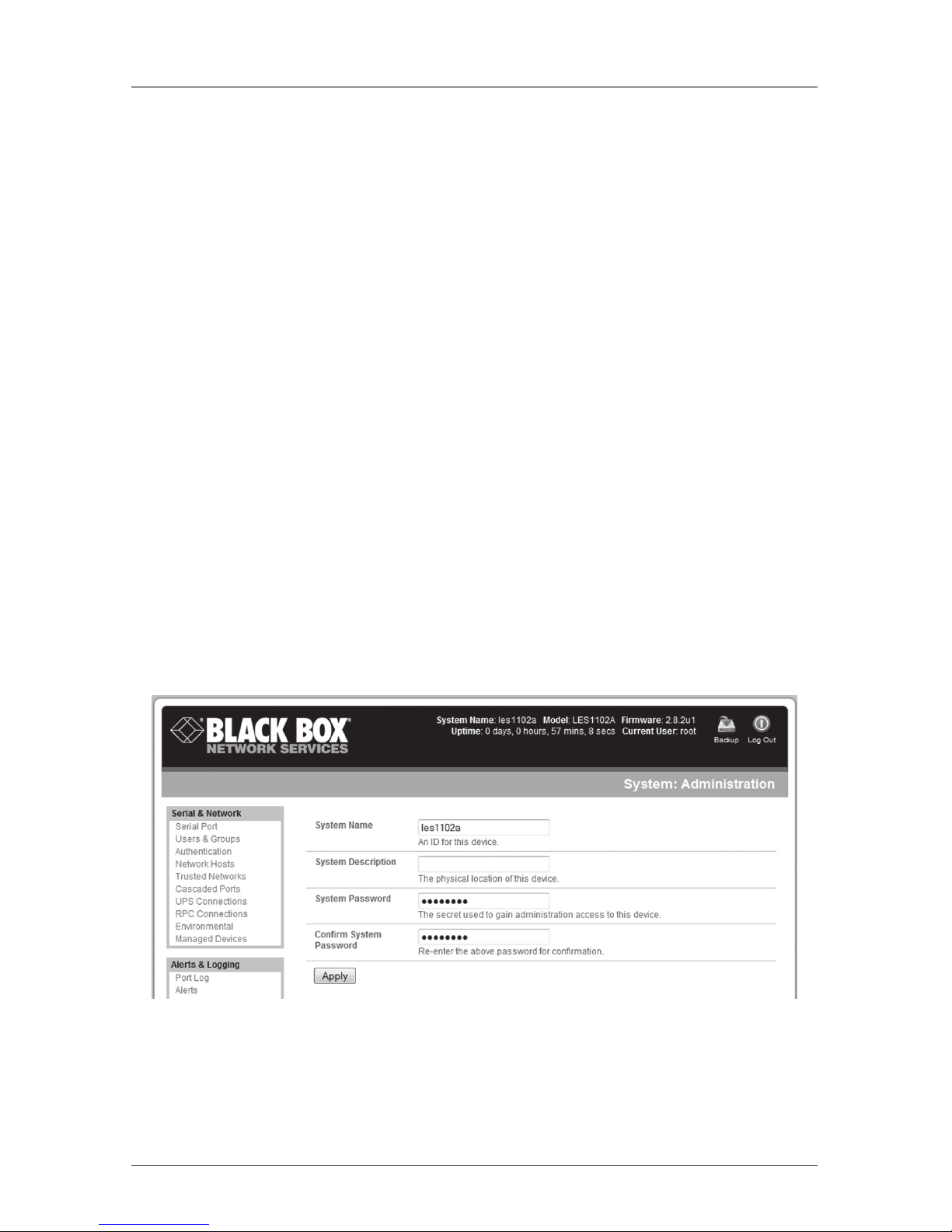
• Select “System: Administration,” enter and conrm a new system password,
and click “Apply.”
System: Administration screen.
• To assign your serial device server a static IP address or to permanently enable
DHCP, select “System: IP” then “Network Interface” and check “DHCP” or
“Static” for conguration method.
Page 4
Page 4
724-746-5500 | blackbox.com
1102 Secure Device Server Quick Start Guide
Step 4: Configure serial and network devices.
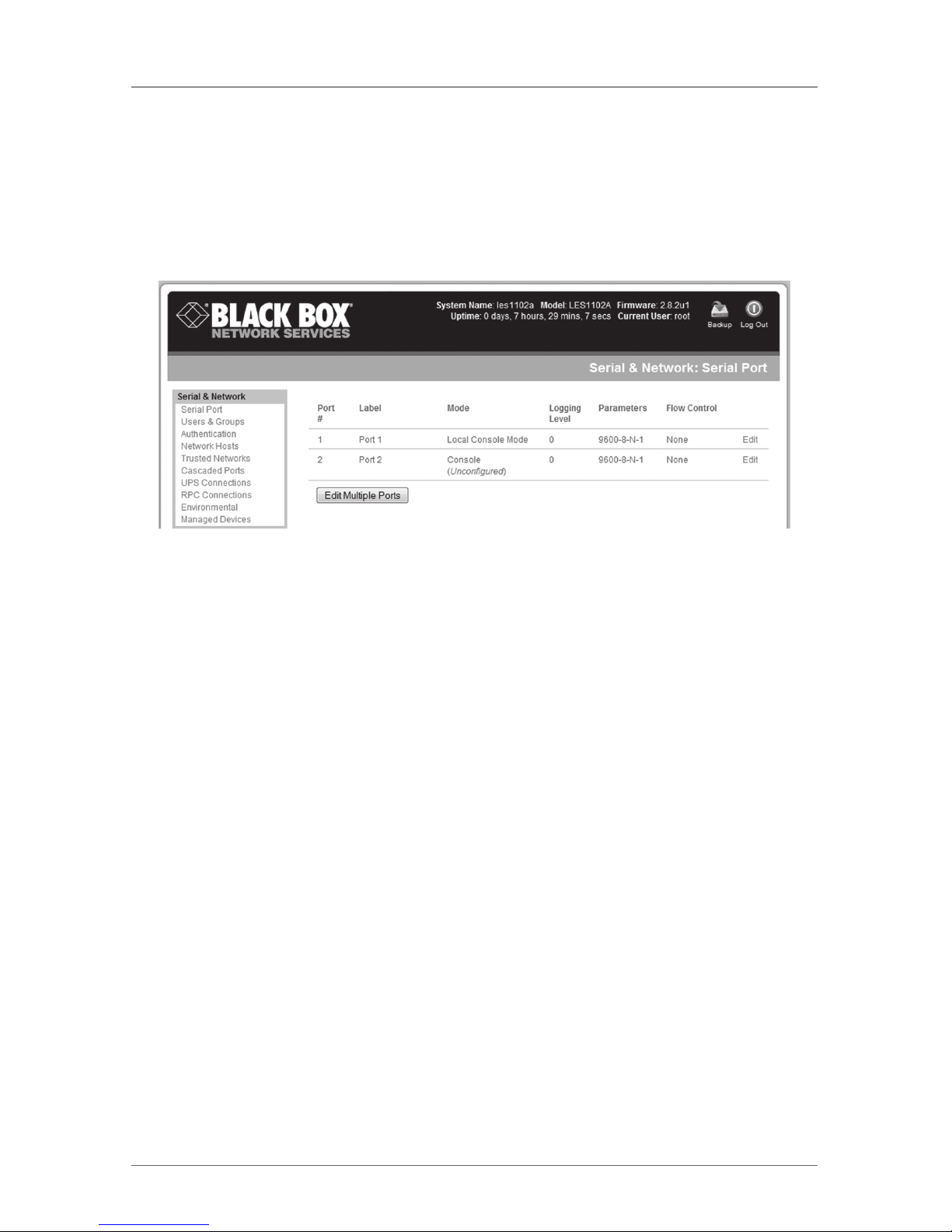
• Select “Serial & Network: Serial Port,” which will display the label, mode, and
protocol options currently set for the serial port. By default, the two serial
ports are set to console server mode (see the user‘s manual for other modes).
Serial & Network: Serial Port screen.
• To congure a serial port, click “Edit.”
• Congure the common settings (baud rate, parity, data bits, stop bits, and
flow control) to match those of the serial device being controlled.
• Select the console server protocols (Telnet, SSH, TCP, and RFC2217) that will
be used for the data connection to the serial port.
NOTE: On Port 1, you have the option to configure the port for modem access.
If you plan to use out-of-band (OoB) dial-in access, connect this serial
port to an external modem.
• Click “Apply.”
• To enable access through the console server to a locally networked computer
(referred to as a host), select “Serial & Network: Network Hosts” and click
“Add Host.”
Page 5
Page 5
724-746-5500 | blackbox.com
1102 Secure Device Server Quick Start Guide
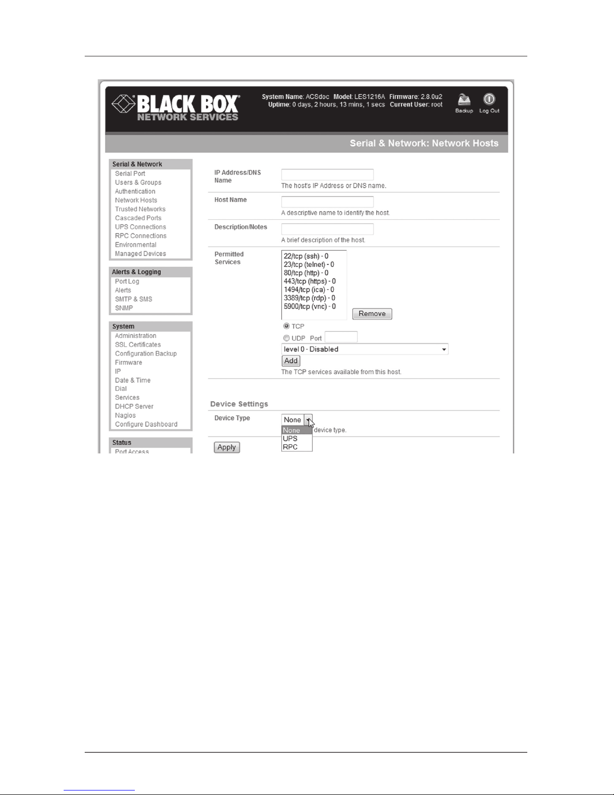
Serial & Network: Network Hosts screen.
• Enter the IP address/DNS name of the host.
• Edit the permitted services used for accessing this host, for example, HTTPS
(TCP port 443), VNC (TCP port 5900), or add custom TCP or UDP port
numbers—only the services specified here are tunneled through to the host.
All other services are blocked.
• Specify the level of information to be logged and monitored for each host
access.
• Click “Apply.”
Page 6
Page 6
724-746-5500 | blackbox.com
1102 Secure Device Server Quick Start Guide
Step 5: Add new users.
NOTE: We recommend that you set up a new Administrator user (in the admin
group with full access privileges) and log in as this new user for all ongoing administration functions (rather than continuing as root).
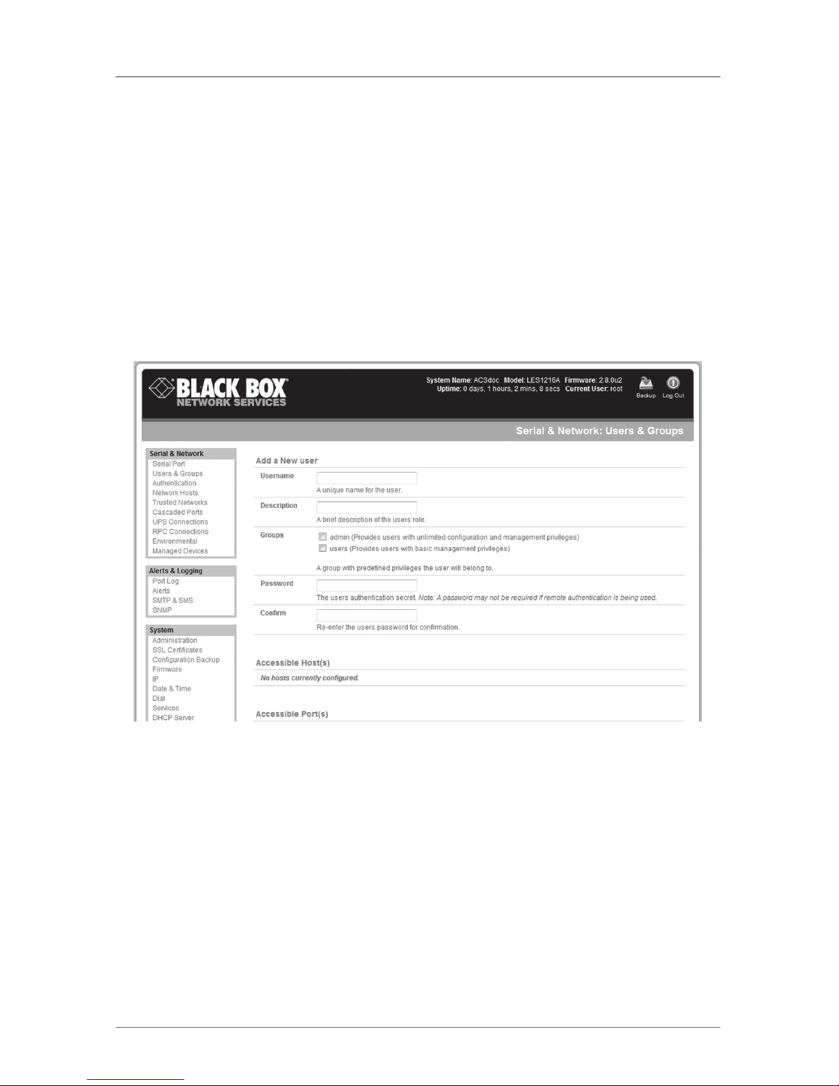
• For each new user, select “Serial & Network: Users & Groups” and click “Add
User.”
• Enter a username and enter and conrm a password, and nominate the
accessible hosts and accessible ports the user is allowed to access.
Serial & Network: Users & Groups screen.
• To grant limited access to the management console, check the “User” group.
To grant full access to the management console, check the “Admin” group.
By default, the user is granted no management console access.
• Click “Apply.”
Page 7

Page 7
724-746-5500 | blackbox.com
1102 Secure Device Server Quick Start Guide
Step 6: Advanced configurations.
The console server offers many more advanced functions including:
• The Alerts & Logging: Alerts facility monitors serial ports, hosts, user logins,
UPSs (uninterruptible power supplies), and RPCs (remote power controllers
such as PDUs and IPMI devices). A broad selection of trigger events
(such as data patterns, temperature, or battery levels) can be specified.
When triggered, a warning e-mail, SMS, Nagios®, or SNMP alert is sent to a
nominated destination.
• Extensive management of UPSs and RPCs using Open Source NUT and Powerman tools. The Manage: Power facility enables both administrators and regular users to monitor and control attached PDU power strips, and servers with
embedded IPMI BMCs.
• Historical logs of all communications with serial and network-attached devices, system activity, UPS and PDU power status, environmental status, etc. The
level of logging is set as ports and devices are congured. Alerts & Logging:
Port Log allows this history to be saved locally or remotely. Logs can be viewed
from the Status and Manage menus.
• Other advanced features, such as serial port cascading, remote authentication, trusted networks, secure tunneling, Nagios distributed monitoring, and
the command line interface are covered in detail in the user manual on the
CD-ROM.
NOTE: On the CD-ROM you will also find the SDT Connector software tool.
Once you have configured the console server, this tool provides you with
secure, point-and-click access to the console server and all the attached
devices. Refer to the provided SDT Connector Quick Start for details on
setting up remote management of the console server and connected
devices.
Page 8
Black Box Tech Support: FREE! Live. 24/7.
Tech support the
way it should be.
Great tech support is just 20 seconds away at
724-746-5500 or blackbox.com.
724-746-5500 | blackbox.com
About Black Box
Black Box Network Services is your source for more than 118,000 networking
and infrastructure products. You’ll find everything from cabinets and racks and
power and surge protection products to media converters and Ethernet switches
all supported by free, live 24/7 Tech support available in 20 seconds or less.
©
Copyright 2010. All rights reserved.
 Loading...