

Black Box LE7500A, LE7500A-12, LE7500A-12P, LE7500A-16, LE7500A-17 Installation & User Manual
Page 1
INTELLIGENT
MEDIA CONVERTER
™
LE7500A MODULES
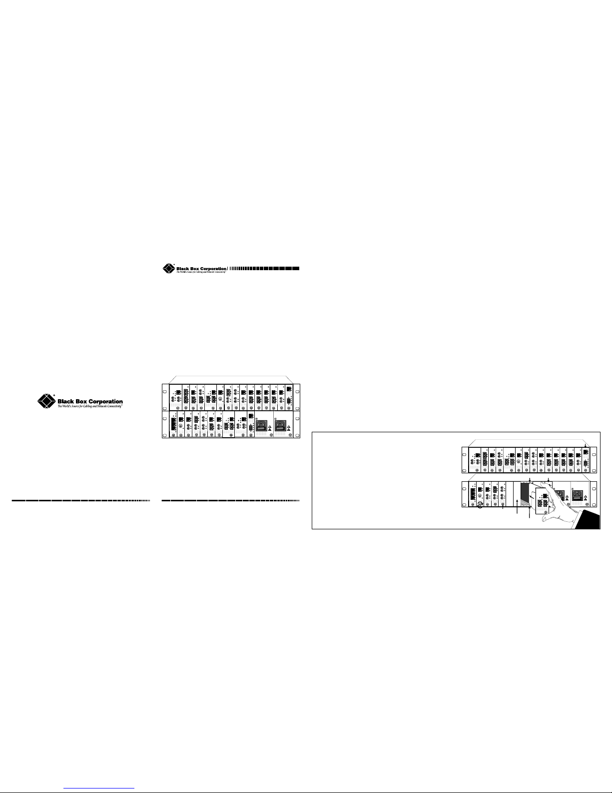
Installing the Intelligent Media Converter Modules
• The LE7501A Management Module can only be installed in the far
right-hand slot. See diagram.
• Intelligent “redundant twister”
™
modules have DIP switches that must
be set prior to installation. Refer to the
Intelligent Media Converter
“redundant twister” Module Installation & User Guide
for more details.
• Intelligent “redundant twister” F/O modules require two slots.
• Modules must be firmly secured to the chassis before network
connections are made.
Follow the simple steps outlined below:
1. Grasp a module by the front panel as shown and insert into a slot
making sure that both the top and bottom of the card edges are lined
up with the top and bottom card guides.
2. Slide the module in until the top and bottom edges of the front panel
are flush and even with the top and bottom edges of the chassis and
secure to the chassis by turning the thumb screw clockwise until snug.
Specifications: 100Mbps Intelligent “twister” Modules
Data Rate ____________ 100Mbps half-duplex; 200Mbps full-duplex
Bit Delay _________________________________________ < 40 bits
Twisted-Pair Interface
Connector __________________________ Shielded RJ-45, 8-pin jack
Impedence ________________________________ 100 Ohms nominal
Signal Level Output (differential) ______________________ .95 to 1.05V
Signal Level Input _____________________________ 350mV minimum
Supported Link Length____________________________________ 100m
Cable Type ___________________________________Category 5 UTP
Multimode F/O Interface
Connector ________________________________________ ST or SC
RX Input Sensitivity _______________________ -31 dBm peak minimum
Output Power ___________________ -14 dBm to -23.5 dBm (50/125 µm)
___________________ -14 dBm to -20 dBm (62.5/125 µm)
Supported Link Length_______________________ up to 2km full duplex
Cable Type ____________________ 50/125, 62.5/125, 100/140 µm F/O
Singlemode F/O Interface
Connector ________________________________________ ST or SC
RX Input Sensitivity _______________________ -31 dBm peak minimum
Output Power ______________________ -8 dBm to -15 dBm (9/125 µm)
Supported Link Length______________________ up to 15km full duplex
Cable Type ________________ 8.3/125, 8.7/125, 9/125, 10/125 µm F/O
Singlemode F/O Interface — extended distance support
Connector _____________________________________________ SC
RX Input Sensitivity ___________________________ -35 dBm minimum
Output Power ________________________ 0 dBm to -5 dBm (9/125 µm)
Supported Link Length______________________ up to 40km full duplex
Cable Type ________________ 8.3/125, 8.7/125, 9/125, 10/125 µm F/O
10 BASE
LK
AT
LK
AT
PWR
R
X
TP
FL
T
X
10 BASE
LK
AT
LK
AT
PWR
R
X
TP
FL
T
X
DISCONNECT ALL POWER
SOURCES BEFORE SERVICING
AC IN
100-240V
50/60Hz
2A
DISCONNECT ALL POWER
SOURCES BEFORE SERVICING
AC IN
100-240V
50/60Hz
2A
MGT-10
LK
AT
C
O
N
S
O
L
E
T
P
PWR
A
B
R
ER
MGT-10
LK
AT
C
O
N
S
O
L
E
T
P
PWR
A
B
R
ER
10 BASE
LK
AT
COL
PWR
TP
BNC
10 BASE
LK
AT
COL
PWR
TP
BNC
10 BASE
LK
AT
LK
AT
PWR
R
X
TP
FL
T
X
10 BASE
LK
AT
LK
AT
PWR
R
X
TP
FL
T
X
100 BASE
LK
AT
LK
AT
PWR
R
X
T
X
R
X
M
M
S
M
T
X
100 BASE
LK
AT
LK
AT
PWR
R
X
S
M
T
X
R
X
T
X
M
M
100 BASE
LK
AT
LK
AT
PWR
R
X
T
X
M
M
R
X
T
X
S
M
100 BASE
LK
AT
LK
AT
PWR
R
X
S
M
T
X
R
X
M
M
T
X
100 BASE
LK
AT
LK
AT
PWR
R
X
S
M
T
X
R
X
T
X
M
M
100 BASE
LK
AT
LK
AT
PWR
R
X
S
M
T
X
R
X
M
M
T
X
100 BASE
LK
AT
LK
AT
PWR
R
X
TX
FX
T
X
100 BASE
LK
AT
LK
AT
PWR
R
X
TX
FX
T
X
100 BASE
LK
AT
LK
AT
PWR
R
X
TX
FX
T
X
100 BASE
LK
AT
LK
AT
PWR
R
X
TX
FX
T
X
100 BASE
LK
AT
LK
AT
PWR
R
X
TX
FX
T
X
100 BASE
LK
AT
LK
AT
PWR
R
X
TX
FX
T
X
100 BASE
“redundant twister”
™
MAIN
RESET
LK
AT
PRIMARY
LK
AT
SECONDARY
LK
AT
R
X
T
X
R
X
T
X
PWR
SW
100 BASE
“redundant twister”
™
MAIN
RESET
LK
AT
PRIMARY
LK
AT
SECONDARY
LK
AT
R
X
T
X
R
X
T
X
PWR
SW
100 BASE
“redundant twister”
™
MAIN
RESET
LK
AT
PRIMARY
LK
AT
SECONDARY
LK
AT
R
X
T
X
R
X
T
X
PWR
SW
100 BASE
“redundant twister”
™
MAIN
RESET
LK
AT
PRIMARY
LK
AT
SECONDARY
LK
AT
R
X
T
X
R
X
T
X
PWR
SW
100 BASE
M
A
I
N
P
R
I
S
E
C
RESET
LK
AT
LK
AT
LK
AT
SEC
PWR
SW
Intelligent Media Converter™ 7500 Intelligent Media Converter™ 7500
Specifications: 10Mbps Intelligent “twister” Modules
Data Rate ______________ 10Mbps half-duplex; 20Mbps full-duplex
Bit Delay __________________________________________ < 5 bits
Twisted-Pair Interface
Connector __________________________ Shielded RJ-45, 8-pin jack
Impedence ________________________________ 100 Ohms nominal
Signal Level Output __________________________________2.0 to 2.8V
Signal Level Input _____________________________ 350mV minimum
Supported Link Length ____________________________________ 100m
Cable Type _____________________________ Category 3, 4 or 5 UTP
Multimode F/O Interface
Connector ______________________________________ ST or SMA
RX Input Sensitivity ___________ 10BASE-FL -32.5 dBm peak minimum
Output Power _________________ -21.8 dBm to -16.8 dBm (50/125 µm)
___________________ -19 dBm to -14 dBm (62.5/125 µm)
Supported Link Length _______________________ up to 2km full duplex
Cable Type ____________________ 50/125, 62.4/125, 100/140 µm F/O
Singlemode F/O Interface
Connector _____________________________________________ ST
RX Input Sensitivity ___________ 10BASE-FL -32.5 dBm peak minimum
Output Power _____________________ -17 dBm to -23 dBm (9/125 µm)
Supported Link Length _______________________ up to 8km full duplex
Cable Type ________________ 8.3/125, 8.7/125, 9/125, 10/125 µm F/O
Thinnet Coax Interface
Connector ___________________________________ BNC receptacle
Internal Transceiver _________________________________ IEEE 802.3
Termination _____________________________ User Selectable Jumper
Supported Link Length ________________________________up to 185m
Cable Type _______________________________ RG-58 coaxial cable
10 BASE
LK
AT
LK
AT
PWR
R
X
TP
FL
T
X
MGT-10
LK
AT
C
O
N
S
O
L
E
T
P
PWR
A
B
R
ER
10 BASE
LK
AT
COL
PWR
TP
BNC
10 BASE
LK
AT
LK
AT
PWR
R
X
TP
FL
T
X
10 BASE
LK
AT
LK
AT
PWR
R
X
TP
FL
T
X
100 BASE
LK
AT
LK
AT
PWR
R
X
T
X
R
X
M
M
S
M
T
X
100 BASE
LK
AT
LK
AT
PWR
R
X
T
X
M
M
R
X
T
X
S
M
100 BASE
LK
AT
LK
AT
PWR
R
X
S
M
T
X
R
X
T
X
M
M
100 BASE
LK
AT
LK
AT
PWR
R
X
S
M
T
X
R
X
M
M
T
X
100 BASE
LK
AT
LK
AT
PWR
R
X
TX
FX
T
X
100 BASE
LK
AT
LK
AT
PWR
R
X
TX
FX
T
X
100 BASE
LK
AT
LK
AT
PWR
R
X
TX
FX
T
X
100 BASE
LK
AT
LK
AT
PWR
R
X
TX
FX
T
X
100 BASE
“redundant twister”
™
MAIN
RESET
LK
AT
PRIMARY
LK
AT
SECONDARY
LK
AT
R
X
T
X
R
X
T
X
PWR
SW
100 BASE
“redundant twister”
™
MAIN
RESET
LK
AT
PRIMARY
LK
AT
SECONDARY
LK
AT
R
X
T
X
R
X
T
X
PWR
SW
10 BASE
LK
AT
LK
AT
PWR
R
X
TP
FL
T
X
DISCONNECT ALL POWER
SOURCES BEFORE SERVICING
AC IN
100-240V
50/60Hz
2A
DISCONNECT ALL POWER
SOURCES BEFORE SERVICING
AC IN
100-240V
50/60Hz
2A
MGT-10
LK
AT
C
O
N
S
O
L
E
T
P
PWR
A
B
R
ER
10 BASE
LK
AT
COL
PWR
TP
BNC
100 BASE
LK
AT
LK
AT
PWR
R
X
S
M
T
X
R
X
T
X
M
M
100 BASE
LK
AT
LK
AT
PWR
R
X
S
M
T
X
R
X
M
M
T
X
100 BASE
LK
AT
LK
AT
PWR
R
X
TX
FX
T
X
100 BASE
LK
AT
LK
AT
PWR
R
X
TX
FX
T
X
100 BASE
“redundant twister”
™
MAIN
RESET
LK
AT
PRIMARY
LK
AT
SECONDARY
LK
AT
R
X
T
X
R
X
T
X
PWR
SW
100 BASE
“redundant twister”
™
MAIN
RESET
LK
AT
PRIMARY
LK
AT
SECONDARY
LK
AT
R
X
T
X
R
X
T
X
PWR
SW
100 BASE
M
A
I
N
P
R
I
S
E
C
RESET
LK
AT
LK
AT
LK
AT
SEC
PWR
SW
Card Guide
Blank Panel
Card Guide
Slot for Management Module
Slot for Management Module
Thumb Screw
100 BASE
“redundant twister”
™
MAIN
RESET
LK
AT
PRIMARY
LK
AT
SECONDARY
LK
AT
R
X
T
X
R
X
T
X
PWR
SW
IMPORTANT!
Tighten thumb screw
to secure each module firmly
to chassis before making
network connections.
Intelligent Media Converter™ 7500 Intelligent Media Converter™ 7500
Installation & User Guide
5660-750002-002 A
8/99
JULY 1999
LE7500A-12
LE7500A-12P
LE7500A-16
LE7500A-17
© Copyright 1999. Black Box Corporation. All rights reserved.
1000 Park Drive • Lawrence, PA 15055-1018 • 724-746-5500 • Fax 724-746-0746
Any trademarks or trade names that appear in this document are
the property of their respective owners.
The information contained in this document is assumed to be correct and
current. The manufacturer is not responsible for errors or omissions and
reserves the right to change specifications at any time without notice.
CUSTOMER SUPPORT INFORMATION
Order toll-free in the U.S. 24 hours, 7 A.M. Monday to midnight Friday: 877-877-BBOX
FREE technical support, 24 hours a day, 7 days a week: 724-746-5500 (fax 724-746-0746)
Mail order: Black Box Corporation, 1000 Park Drive, Lawrence, PA 15055-1018
Web site: www.blackbox.com • E-mail: info@blackbox.com
Page 2
100Mbps Intelligent “redundant twister” Modules:
LH7731A-RTX RJ-45 to Redundant RJ-45 _______________ 100m/100m
LH7731A-RFXSC RJ-45 to Redundant FX multimode SC ____ 100m/2km
LH7731A-RFXSCSM RJ-45 to Redundant FX singlemode SC 100m/15km
LH7731A-RFXST RJ-45 to Redundant FX multimode ST ____ 100m/2km
LH7731A-RFXSTSM RJ-45 to Redundant FX singlemode ST _ 100m/15km
10Mbps Intelligent “redundant twister” Module:
LH7111A-TP RJ-45 to Redundant RJ-45 ________________ 100m/100m
These modules incorporate three ports: a MAIN, a PRIMARY and a
SECONDARY port. Full redundant data paths are provided between the
PRIMARY and the SECONDARY ports.
LED Operation:
• PWR: normal operation
•SW: SECONDARY port active at some point; functions in
Dynamic Recovery Mode only
• SECONDARY: port is active (PRIMARY is inactive)
• (MAIN) LK: valid link indication
• (MAIN) AT: receiving data
• (PRIMARY) LK: valid link indication
• (PRIMARY) AT: receiving data
• (SECONDARY) LK: valid link indication
• (SECONDARY) AT: receiving data
MDI-II to MDI-X Switch: MDI-II (default)
DIP Switch Settings:
• TX Switch UP: data from the MAIN port is transmitted simultaneously
on the PRIMARY and SECONDAR Y ports; data from the active port
(PRIMARY or SECONDARY) is transmitted on the MAIN port. NOTE:
the Link Switch must also be UP in order to send data out the inactive port.
• TX Switch DOWN (default): data from MAIN port is transmitted on
active port only.
• AUTO Switch UP: module automatically reverts back to the PRIMARY
port when the primary link is re-established.
• AUTO Switch DOWN (default): once the SECONDARY port has become
active, the module
will not revert back to the PRIMARY port when the
primary link is re-established, unless the SECONDARY link is absent.
100Mpbs TX-to-FX Intelligent “twister” Modules:
LH7131A-SXSC RJ-45 to SX multimode SC _____________ 100m/300m
LH7131A-SXST RJ-45 to SX multimode ST _____________ 100m/300m
LH7131A-SC RJ-45 to FX multimode SC ________________ 100m/2km
LH7131A-SMSC RJ-45 to FX singlemode SC____________ 100m/15km
LH7131A-ST RJ-45 to FX multimode ST ________________ 100m/2km
LH7131A-SMST RJ-45 to FX singlemode ST ____________ 100m/15km
LH7131A-PSC RJ-45 to FX singlemode SC _____________ 100m/40km
These modules provide high-speed transparent integration of
100BASE-TX and 100BASE-FX segments.
LED Operation:
• PWR: normal operation
• LK: satisfactory receive link status on respective port
•AT: receiving data
MDI-II to MDI-X Switch: MDI-II (default)
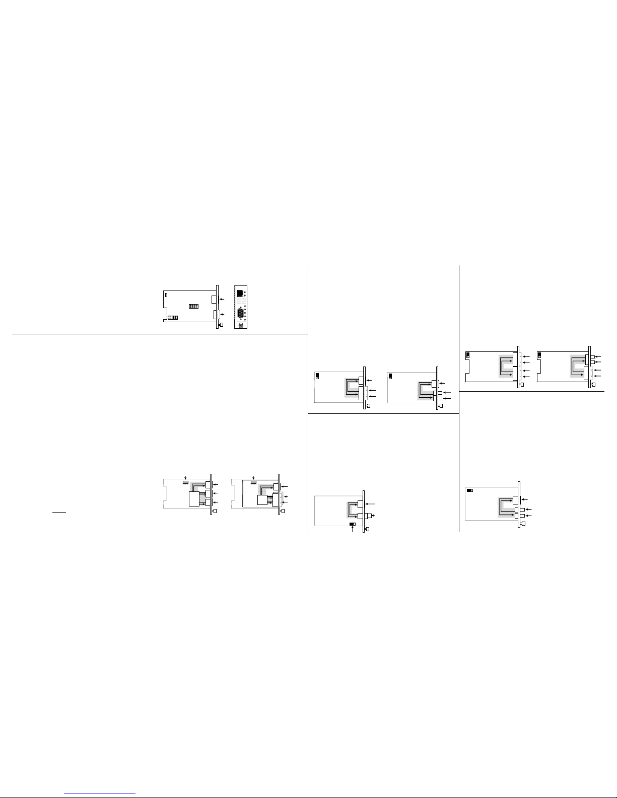
Jumper Settings: A jumper switch configures the Link Loss Carry
Forward (LLCF) function.
• To enable LLCF: connect pins 1&2
• To disable LLCF: connect pins 2&3 (default)
100Mbps SM-to-MM Intelligent “twister” Modules:
LH7131A-SCSC FX multimode SC to FX singlemode SC ___ 2km/15km
LH7131A-SCST FX multimode SC to FX singlemode ST ___ 2km/15km
LH7131A-STSC FX multimode ST to FX singlemode SC ___ 2km/15km
LH7131A-STST FX multimode ST to FX singlemode ST ____ 2km/15km
These modules provide seamless integration between higher bandwidth
singlemode and multimode fiber optic segments.
LED Operation:
• PWR: normal operation
• LK: satisfactory link status on respective port
•AT: receiving data
Jumper Settings: A jumper switch configures the Link Loss Carry
Forward (LLCF) function.
• To enable LLCF: connect pins 1&2
• To disable LLCF: connect pins 2&3 (default)
10Mbps Thinnet Coaxial Intelligent “twister” Module:
LE7111A-BNC RJ-45 to BNC ________________________ 100m/185m
This module provides twisted-pair to Thinnet coax segment integration.
LED Operation:
• PWR: normal operation
• LK: satisfactory receive link status on TP port
•AT: receiving data
• COL: detection of collision condition
MDI-II to MDI-X Switch: MDI-II (default)
Jumper Settings: A jumper is used to set either internal or external
termination of the BNC port.
• To enable internal 50Ω termination: connect pins 1&2
• To enable use of external termination: connect pins 2&3 (default)
RJ-45
BNC
Jumper JP4 Termination
JP4
31
RJ-45
F/O ST/SMA/SC
LLCF
3 2 1
10Mbps F/O Intelligent “twister” Modules:
LE7111A-FSC RJ-45 to FL multimode SC________________ 100m/2km
LE7111A-FST RJ-45 to FL multimode ST________________ 100m/2km
LE7111A-SFST RJ-45 to FL singlemode ST ______________ 100m/8km
LE7111A-FSMA RJ-45 to FL multimode SMA ____________ 100m/2km
These modules provide transparent integration of 10BASE-T and
10BASE-FL segments.
LED Operation:
• PWR: normal operation
• LK: satisfactory receive link status on respective port
•AT: receiving data
MDI-II to MDI-X Switch: MDI-II (default)
Jumper Settings: A jumper switch configures the Link Loss Carry
Forward (LLCF) function.
• To enable LLCF: connect pins 1&2
• To disable LLCF: connect pins 2&3 (default)
RJ-45
DIP Switches
F/O SC (ST)
F/O SC (ST)
DIP Switches
RJ-45
RJ-45
RJ-45
12345
RED
LLCF
LINK
AUTO
TX
12345
RED
LLCF
LINK
AUTO
TX
RJ-45
F/O SC
RJ-45
F/O ST
LLCF
3
2
1
LLCF
3
2
1
F/O SC
F/O SC
F/O SC
F/O ST
LLCF
3
2
1
LLCF
3
2
1
• LINK Switch UP: module sends link on both the PRIMARY and SECONDARY ports; the end station connected to the module sees a valid link state.
• LINK Switch DOWN (default): module sends link on the active port only;
the end station connected to the module sees a valid link state only if the
port on the module is active.
• LLCF Switch UP: Link Loss Carry Forward is enabled.
• LLCF Switch DOWN (default): Link Loss Carry Forward is disabled.
• RED Switch UP (default): redundancy is enabled; Operates in Dynamic
Recovery Mode (DRM).
• RED Switch DOWN: redundancy is disabled; Network Select Mode (NSM)
is enabled. NOTE: In this mode the reset push button toggles the active
port between A and B for each switch closure. The AUTO switch sets the
initial active port on power up: UP for SECONDARY; DOWN for
PRIMARY. The SW LED remains OFF in NSM.
DIP switches can be managed with console commands or with NetBeacon
™
Management Software. Refer to the Intelligent Media Converter™ Command
Line Interface Guide, or the NetBeacon
™
Management Software
Installation & User Guide for software management information. For more
information on the Intelligent “redundant twister” modules, refer to the
Intelligent Media Converter “redundant twister”™ Installation & User
Guide.
LE7501A Management Module
Connected to the modules in the chassis via the backplane, this SNMP
agent reports individual board status to the network management software.
TP Data Rate: 10Mbps half-duplex; 20Mbps full-duplex
LED Operation:
• (TP) LK: link present
• (TP) AT: link present and packet received
• PWR: power supply present and ON
• (Console) A: power supply A present and ON
• (Console) B: power supply B present and ON
• (Console) R: system is operational
• (Console) ER: indicates system diagnostics or boot failure
PC Terminal Session Parameters:
9600 Baud / 8 data bit / 1 stop bit / No Parity / No Flow Control
Refer to the Intelligent Media Converter
™
LE7500A Installation & User
Guide for information on booting the LE7501A Management Module. Refer
to the Intelligent Media Converter
™
Command Line Interface Guide for
the software commands.
IMPORTANT: When setting DIP Switches: UP is furthest from the circuit board.
DOWN is closest to the circuit board.
NOTE: Link Loss Carry Forward (LLCF) functionality is incorporated on all intelligent twister modules with the exception of the LE7111A-BNC
module. Refer to the
Intelligent Media Converter™ LE7500A Installation & User Guide
for a complete description.
RJ-45
DB-9
JP2
JP3
JP1
MGT-10
LK
AT
C
O
N
S
O
L
E
T
P
PWR
A
B
R
ER
 Loading...