

Black Box LE740-TPSTS20, LE740-BNSTM, LE740-TPBNC, LE7408A, LE740-SMMM2 Installation Manual
...Page 1
1
Modular Media Converter Installation Guide
(includes 10 Mbps Ethernet, 100 Mbps Fast Ethernet and
Protocol-Independent Fiber Mode Conversion Modules)
Modular Media Converters are designed to convert between 100Base-TX,
100Base-FX and 100Base-FX-SingleMode Fast Ethernet cabling, 10Base-2,
10Base-T, 10Base-FL and 10Base-FL-SingleMode Ethernet cabling or protocolindependent single/multi-mode fiber optic cabling.
About Media Converter Chassis
Media Converter modular chassis are user-configurable, provide power to
the media conversion module and are available with one, four, eight or 12
slots for installing any combination of interchangeable media conversion
modules that include 10 Mbps Ethernet Modules, 100 Mbps Fast Ethernet
Modules and S2MM Module Sets (protocol-independent single/multi-mode
fiber). For example an 8-Port Media Converter can be configured with one to
eight 10 Mbps Modules and 100 Mbps Modules or one to four S2MM Module
Sets in any combination.
Note: S2MM Module Sets consist of two modules and require two media conversion
module slots so they can not be used in a 1-Port chassis.
1-Port (LE7401A and LE7401A-R2) and 4-Port (LE7404A) Media Converters
are stand-alone chassis that include one or four media conversion module
slots, respectively, and a fixed 95/240 VAC power supply. 8-Port Media
Converters (LE7408A) are 1U high, rackmountable, include eight media
conversion module slots and a fixed 95/240 VAC power supply. There are
two 12-Port Media Converter chassis; both are rackmountable and include
12 media conversion module slots and either a 95/240 VAC or -48 VDC
Power Supply Module with an additional slot for installing a second faulttolerant Power Supply Module. The basic differences between the two are
the chassis’ height and location of the Power Supply Modules. The 12-Port
Media Converter 1U (LE7412A and LE7412A-DC) has the power on the rear
side of the chassis with media conversion module slots on the opposite side,
and is 1U high. The 12-Port Media Converter 2U (LE4712A-2 and LE7412A-
2DC) has both power and media conversion module slots on the front of the
chassis and is 2U high.
LE740-TPSTM LE740-TPSTS20 LE740-TPBNC LE7408A
LE740-BNSTM LE740-SMMM2 LE740-SMMM LE7404A
LH740-TPSCM LH740-TPSTS LH740-TPSCS LE7401A
LH740-TPSTS20 LH740-TPSCS20 LE7412A LE7401A-R2
LE7412A-DC LE7412A-2DC LH740-TPSTM LE7412A-2
LE740-TPSTS
About 10 Mbps Media Conversion Modules
Media conversion modules for 10 Mbps Ethernet have two different
types of ports on them and require one slot in a Media Converter chassis for
a single 10 Mbps Ethernet conversion. The following versions of 10 Mbps
Modules are available:
10BT (RJ-45) - 10BFL Module (half- or full-duplex) — converts 10Base-T
(RJ-45) to 10Base-FL 850 multi-mode fiber; includes one pair ST
(LE740-TPSTM) connectors
10BT (RJ-45) - 10BFL SM Module (half- or full-duplex) — converts
10Base-T (RJ-45) to single-mode fiber; includes one pair ST
(LE740-TPSTS) connectors
10BT (RJ-45) - 10BFL SM/PLUS Module (half- or full-duplex) — same as
above only with higher power budget; includes one pair ST (LE740TPSTS20) connectors
10BT (RJ-45) - 10B2 (BNC) Module — converts 10Base-T (RJ-45) to
10Base-2 (LE740-TPBNC)
10B2 (BNC) - 10BFL Module — converts 10Base-2 to 10Base-FL multi-
mode fiber; includes one pair ST (LE740-BNSTM) connectors
About 100 Mbps Media Conversion Modules
Media conversion modules for 100 Mbps Fast Ethernet have two
different types of ports on them and require one slot for a single 100 Mbps
Fast Ethernet conversion. The following 100 Mbps Modules are available:
100B TX - 100B FX Module (half- or full-duplex) — converts 100Base-TX
(RJ-45) to 100Base-FX multi-mode fiber; includes one pair ST
(LH740-TPSTM) or SC (LH740-TPSCM) connectors
100B TX - 100B FX SM Module (half- or full-duplex) — converts 100Base-
TX (RJ-45) to single-mode fiber; includes one pair ST
(LH740-TPSTS) or SC (LH740-TPSCS) connectors
100B TX - 100B FX SM/PLUS Module (half- or full-duplex) — as above
with higher power budget; includes one pair ST (LH740-TPSTS20) or
SC (LH740-TPSCS20) connectors
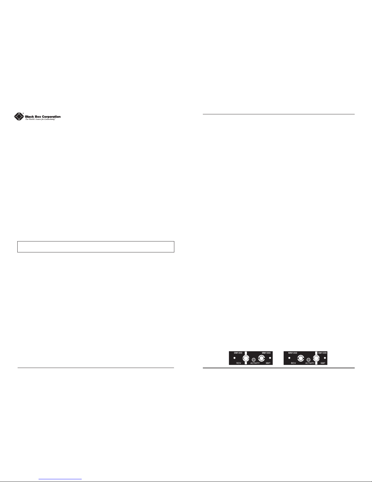
About Protocol-Independent Fiber Mode Conversion Module Sets
To do a fiber mode conversion, S2MM Module Sets are used. Unlike 100
Mbps Modules and 10 Mbps Modules, each S2MM Module Set consists of
two modules and requires two slots in a Media Converter chassis to do a
single conversion. One module in the set has a single-mode receive (RCV)
port and a multi-mode transmit (XMT) port. The other module has a multimode receive (RCV) port and a single-mode transmit (XMT) port. The
single-mode port is identified by a solid white bar on each of the modules.
2
Page 2
S2MM Module Sets use LED transmitters and are available for the
following conversions:
S2MM1300 Module Set (LE740-SMMM2) — converts 1300-nm single-
mode to 1300-nm multi-mode fiber (ST)
S2MM1300/PLUS Module Set (LE740-SMMM) — same as above
only single-mode has higher power budget
NOTE: 10 Mbps Modules, 100 Mbps Modules and S2MM Module Sets will be
referred to as “Media Conversion Modules” throughout the rest of this document
except where differences need to be indicated.
Configuring Media Conversion Modules
Before installing, media conversion modules with twisted pair ports may
be configured for LinkLoss and/or either a crossover workstation or passthrough repeater/hub connection (10 Mbps only). Media conversion
modules with fiber ports may be configured for FiberAlert. Port termination
may need setting on 10 Mbps Modules with BNC ports. 10BT (RJ-45) -
10BFL Modules have two additional jumpers, one for shielded/unshielded
twisted pair and one for longer twisted pair distances. 100 Mbps modules
may be configured for Autonegotiation. S2MM Modules Sets come ready to
install.
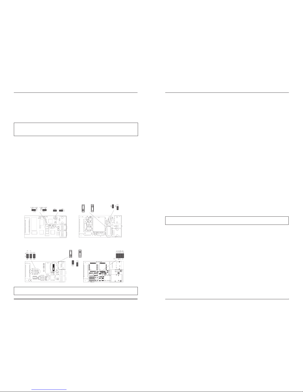
The following diagrams show where the jumpers and switches are
located on the various media conversion modules.
NOTE: Some features may not be available on all versions of media conversion
modules.
TP
Crossover Switch (S1)
Pass-Through/
S1
S1
Crossover
Pass-Through
Default
BNC Termination
Jumper (JP1)
Default
OFFON
10BT (RJ-45) - 10B2 (BNC)
BNC Termination
Jumper (JP2)
FiberAlert
Jumper (JP3)
Default
Default
OFF
ON
10B2 (BNC) - 10BFL
100BTX - 100BFX
Fiber Alert Jumper (JP1)
Autonegotiation Jumper (JP2)
FX LinkLoss Jumper (JP3)
TX LinkLoss Jumper (JP4)
Default
Disabled
Enabled
TP
Crossover Switch (S1)
Pass-Through/
Crossover
Default
S1
S1
Pass-Through
10BT (RJ-45) - 10BFL
Fiber Alert Jumper (JP1)
TP LinkLoss Jumper (JP2)
Twisted Pair
Distance Jumper (JP3)
3
4
Twisted Pair Crossover/Pass-Through Switch
All 10 Mbps Modules with twisted pair ports have one RJ-45 connector
for a single shielded or unshielded twisted pair link segment. Each twisted
pair port features a 2-position switch, located at position S1, for selecting a
crossover workstation connection or pass-through repeater/hub connection.
The switch is labeled with “X” for a crossover connection (factory default)
and a “ll” for a pass-through connection. To select the appropriate setting,
simply move the switch to the proper position before installing the media
conversion module. If uncertain whether crossover or pass-through is
needed, set the switch to the position that makes the link LED glow.
Twisted Pair Cable Type
The twisted pair port on10BT (RJ-45) - 10BFL Modules features a
2-position jumper, located at position JP3, for selecting either a shielded or
unshielded twisted pair link segment. The jumper is labeled with “STP IN”
and “UTP OUT”. An unshielded twisted pair link segment (factory default)
is selected when the shunt is removed or on only one pin. Place the shunt
over both pins for a shielded twisted pair link segment.
Twisted Pair Cable Distance
The twisted pair port on 10BT (RJ-45) - 10BFL Modules features a
2-position jumper, located at position JP2, for selecting longer twisted pair
cable distances (distances greater than 100 meters). The jumper is labeled
with “NORMAL IN” and “LONG OUT”. Place the shunt over both pins for
distances up to 100 meters (factory default). Remove the shunt or place it
on only one pin for distances of 100 meters or more.
NOTE: The product on the other side of the conversion must be able to support
longer cable distances as well.
About LinkLoss and FiberAlert
Some of the aforementioned media conversion modules come with the
following troubleshooting features:
• FO/FX LinkLoss (a.k.a. "Fiber LinkLoss" or "LinkLoss")
• TP/TX LinkLoss (a.k.a. "Twisted Pair LinkLoss” or "Reverse LinkLoss”)
• FiberAlert
FiberAlert and LinkLoss are advanced troubleshooting features that can
help you locate "silent failures" on your network. However, it is vital that
you understand exactly how FiberAlert and LinkLoss work, and how they
will react in your network configuration, before attempting to install the
enclosed module(s).
Page 3

Installing modules without understanding the effects of FiberAlert and
LinkLoss can cause perfectly functioning units to appear flawed or even
dead.
About Link Integrity
During normal operation, link integrity pulses are transmitted by all pointto-point Ethernet devices. When an media converter module
receives valid link pulses, it knows that the device to which it is connected is
up and sending pulses, and that the copper or fiber cable coming from that
device is intact. The appropriate “LNK” (link) LED is lit to indicate this.
The media converter modulealso sends out link pulses from its copper
and fiber transmitters, but normally has no way of knowing whether the
cable to the other device is intact and the link pulses are reaching the other
end. The combination of FiberAlert and LinkLoss allows this information to
be obtained, even when physical access to a remote device (and its link
integrity LED) is not available.
What Is FO/FX LinkLoss?
FO/FX LinkLoss is a troubleshooting feature. When a fault occurs on the
fiber segment of a conversion, FO/FX LinkLoss detects the fault and passes
this information to the twisted pair segment. If a media converter is not
receiving a fiber link, FO/FX LinkLoss disables the transmitter on the media
converter's twisted pair port. This results in a loss of link on the device
connected to the twisted pair port.
What Is TP/TX LinkLoss?
TP/TX LinkLoss is another troubleshooting feature. When a fault occurs on
the twisted pair segment of a conversion, TP/TX LinkLoss detects the fault and
passes this information to the fiber segment. If a media converter is not
receiving a twisted pair link, TP/TX LinkLoss disables the transmitter on the
media converter's fiber port.
What Is FiberAlert?
FiberAlert minimizes the problems
associated with the loss of one strand
of fiber. If a strand is unavailable, the
device at the receiver end notes the
loss of link. The device will then stop
transmitting data and the link signal
until a signal or link pulse is received.
The result is that the link LED on
BOTH sides of the fiber connection will go out indicating a fault somewhere
Cable Break
XMT
RCV
Remote Site
Local Site
LED OFF = Broken Link
Black Box product with enabled —
Remote Site stops transmitting
Local Link LED is OFF indicating a break in the fiber loo
p
FiberAlert
X
LE
D
XM
T
RC
V
5
6
in the fiber loop. Using FiberAlert, a local site administrator is notified of a
fault and can quickly determine where a cable fault is located.
FiberAlert should only be enabled on one side of a media conversion. Enabling it
on both sides would keep both transmitters off indefinitely.
Using FiberAlert and LinkLoss
In a typical central site to remote site media conversion, the
manufacturer recommends you enable your media converters’
troubleshooting features as follows:
FO/FX LinkLoss: Main Site Only
TP/TX LinkLoss: Remote Site Only
FiberAlert: Remote Site Only
This will ensure that any faults, no matter where they occur, can be
detected by an administrator located at the central site.
If you are unsure of how best to implement these features in your
configuration, please contact customer service.
Troubleshooting with LinkLoss and FiberAlert
If LinkLoss is enabled and you lose the connection between the Media
Converter and the hub/switch to which the Media Converter is connected,
disable LinkLoss to assist in pinpointing whether the fault is on the twisted
pair or fiber optic segment. After disabling LinkLoss, if the link is
reestablished with the hub/switch, the problem resides with the fiber
segment. If LinkLoss is disabled and the connection between the Media
Converter and the hub/ switch is NOT reestablished, the failure resides with
the twisted pair segment. When a failure occurs, check that cables are
properly connected. You can also try using another port on the hub/switch
or another cable.
As discussed earlier, FiberAlert stops the fiber optic transmissions as well
as the link LED for the opposite end of the fiber conversion when a
problem occurs with the fiber optic segment. When FiberAlert is enabled
and a fault is detected, disable FiberAlert to determine which side of the
fiber has stopped receiving. When a failure occurs, check that cables are
properly connected. You can also try using another cable.
Configuring Autonegotiation on 100 Mbps Modules
When Autonegotiation is enabled, the media converter negotiates as a
100 Mbps Full-Duplex device; if the device the media converter is
connected to can operate at 100 Mbps Full-Duplex, a link will be
established. If the twisted pair port on the other device does not have the
ability to autonegotiate, or if a 100 Mbps Half-Duplex connection is
desired, Autonegotiation on the media converter must be disabled. Half-
Page 4

7
and Full-Duplex settings must be manually set and match on both devices
the media converters are connected to (see below). The diagram below
show a typical application, followed by a table with three possible
configurations.
Autonegotiation is configured with a 3-pin jumper block located at
position JP3 on 100 Mbps Modules. Enable Autonegotiation by placing the
shunt over pins 1-2. Disable Autonegotiation (factory default) by placing the
shunt over pins 2-3.
BNC Port Termination
10 Mbps Modules with BNC ports feature a 2-pin jumper block located at
position JP1. This jumper block allows a thin coaxial segment to be terminated at the Media Converter without an additional ‘T’ connector and
terminator. If a thin Ethernet segment is to be terminated at the BNC port
on the Media Converter, attach the cable directly to the BNC connector and
set the termination jumper to the ON (enabled, factory default) position by
placing the shunt over both pins.
If the BNC port on the Media Converter is attached to a midpoint of a
thin Ethernet segment, attach a ‘T’ connector to
the BNC port and set the termination jumper to
the OFF (disabled) position by placing the shunt
on only one pin or by removing the shunt.
Note: Thin Ethernet segments must be properly
terminated at both ends and grounded at one end.
If the BNC port is not terminated correctly, the
ACTIVITY light on the front panel will not glow.
Installing Media Conversion Modules
Media conversion modules can be installed in any available media
conversion module slot. Media conversion modules are hot-swappable.
Note: S2MM Module Sets can be installed in any two available slots, but still must
be used as a set to provide a complete conversion. We recommend that each
S2MM Module Set be installed side-by-side (left-to-right or top-to-bottom) to
prevent mismatching module sets. It is necessary to power the unit down before
configuration.
8
Media conversion modules are shipped with brackets for securing them
to the Media Converter chassis. Media conversion modules attach to a
connector inside the Media Converter chassis. To install a module, simply
unscrew the blank bracket covering the slot where the module is to be
installed, slide the module into the chassis, via the cardguides, until the
module is seated securely in the connector. Secure the module to the
chassis by tightening the screws. Then connect the cables.
NOTE: Media Converter chassis are
shipped from the factory with all but
one media conversion module slot
covered with “blank” brackets. Be sure
to keep unused slots covered for EMI
containment. It is a good idea to save any “blanks” removed during installation
for future use if configuration requirements change.
Measuring for Oversaturation
The high power fiber transmitters used on SingleMode/PLUS media
conversion modules can overdrive the receivers and cause data loss if used
in installations where cable power losses are low. To verify this, measure
the optical power at the receiver. The measured power should be no
greater than -14dBm and no less than the Average Receive Sensitivity (listed
in the chart above). If measured power is greater than -14dBm, install an
optical attenuator to bring power within specification. Ideally,
SingleMode/PLUS should be used only where total attenuation of fiber,
connectors and patch cords is greater than 7dB.
Determining Your Power Budget
The maximum distance for a fiber link is determined by the module
installed. The following chart shows the specifications for each of the
available modules:
1
Distances listed are estimates and can vary with application. Distance limitations are determined
by a combination of power budget fiber characteristics, number of connections and other
physical parameters. Subtract 3 dB from Power Loss Budget for 50/125µ multi-mode fiber. HalfDuplex (HDX) distance is limited by IEEE specifications.
2
Values are averages and have been determined under factory conditions. Actual field
application values may vary.
MediaConverter/12x, Front View
Page 5

9
Converting Single/Multi-Mode Fiber Optic
The illustrations below show three typical cabling configurations — (1) a
single-mode connection between an 850nm multi-mode fiber device and a
1300 nm single-mode fiber device, (2) a single-mode connection between
two 850nm multi-mode fiber devices and (3) a single-mode connection
between two OC-3 multi-mode fiber devices.
LED Functions on Media Conversion Modules
Media conversion modules feature diagnostic LEDs that provide
information to help determine where failures reside when they occur in
your network.
LEDs on 10-BT (RJ-45) - 10BFL and 100B TX - 10B FX Modules
The LED locations and functions are virtually the same on 10-BT (RJ-45) 10BFL Modules and 100B TX - 100B FX Modules. The following diagram
shows the LEDs on 10-BT (RJ-45) - 10BFL Modul
es.
The Fiber Link LED glows green when a link is established with the fiber
optic port. The function of the LED next to the Fiber Link LED depends on
whether FiberAlert is enabled. If FiberAlert is disabled, this LED functions as
an Activity LED and flickers amber when activity is detected on the fiber
port. If FiberAlert is enabled, this LED glows amber upon power up, then
flickers when activity is detected on the fiber port. The Twisted Pair Link
LED glows green when a link is established with the twisted pair port. The
Twisted Pair Activity LED flickers amber when activity is detected on the
twisted pair port.
NOTE: On 100 Mbps Modules, the Fiber Activity LED does not reflect whether
FiberAlert is enabled; this LED functions only as an Activity LED.
LEDs on 10BT (RJ-45) - 10B2 Modules
The following diagram shows the LEDs on 10BT (RJ-45) - 10B2 Modules:
The Twisted Pair Link LED glows green when a link is established with the
twisted pair port.
LEDs on 10B2 - 10B FL Modules
The following diagram shows the LEDs on 10B2 - 10B FL Modules.
The Fiber Link LED glows green when a link is established with the fiber
optic port.
Twisted Pair Link LED
Activity LED
10
Page 6

Customer Service Information
Call: (724) 746-5500 Phone orders 24 hours a day, 7:00 AM Monday to
midnight Friday; 8:00 AM to 4:00 PM Saturday (EST)
Fax: (724) 746-0746 or in North America 1-800-321-0746
Mail order: Black Box Corporation, 1000 Park Drive, Lawrence, PA
15055-1018
Technical Support and fax orders 24 hours a day
Federal Communications Commission Radio Frequency Interference Statement
This equipment generates, uses, and can radiate radio frequency energy that may cause interference to
radio communication if not installed and used in strict accordance with the manufacturer’s instructions. It
has been tested and found to comply with the limits for a Class A computing device in accordance with the
specifications in Subpart J of Part 15 of FCC rules, which are designed to provide reasonable protection
against such interference when the equipment is operated in a commercial environment. Operation of this
equipment in a residential area is likely to cause interference, in which case the user at his own expense will
be required to take whatever measures may be necessary to correct the interference.
Changes or modifications not expressly approved by the party responsible for compliance could void the
user’s authority to operate the equipment.
This digital apparatus does not exceed the Class A limits for radio noise emission from digital apparatus
set out in the Radio Interference Regulation of the Canadian Department of Communications.
Le présent appareil numérique n’émet pas de bruits radioélectriques dépassant les limites applicables aux
appareils numériques de classe A prescrites dans le Règlement sur le brouillage radioélectrique publié par le
ministère des Communications du Canada.
Safety Certifications
UL: Listed to UL1950 and CSA 22.2, No. 950, Safety of Information Technology
Equipment, Including Electrical Business Equipment.
TUV/GS: Certified to EN 60 950, Safety of Information Technology Equipment, Including
Electrical Business Equipment.
CE: The products described herein comply with the Council Directive on
Electromagnetic Compatibility (89/336/EEC) and the Council Directive on Electrical
Equipment Designed for use within Certain Voltage Limits (73/23/EEC). For further
details, contact Black Box Corporation.
NOTE: Modules are FCC approved and UL, TUV/GS and CE certified when installed in a Black Box chassis only.
1000 Park Drive • Lawrence, PA 15055-1018 USA
TEL: (724) 746-5500 • FAX: (724) 746-0746
EMAIL: info@blackbox.com
WEB: http://www.blackbox.com
© 1992 - 2001 Black Box Corporation. All rights reserved.
The information in this document is subject to change without notice. Black Box Corporation assumes no responsibility for any
errors that may appear in this document. Specific brands and product names may be trademarks and are the property of their
respective companies.
Document Number 51-80780BB-00 D2 November 2001
12
11
LEDs on S2MM
The following diagram shows the LEDs on an S2MM:
Each module in S2MM Module Sets has one Activity LED. This LED
glows green in normal operation.
Fiber Optic Cleaning Guidelines
Fiber optic transmitters and receivers are extremely susceptible to contamination by
particles of dirt or dust which can obstruct the optic path and cause performance degradation.
Good system performance requires clean optics and connector ferrules.
1) Use fiber patch cords (or connectors, if you terminate your own fiber) only from a
reputable supplier; low quality components can cause many hard-to-diagnose problems
in an installation.
2) Dust caps are installed at the factory to ensure factory-clean optical devices. These
protective caps should not be removed until the moment of connecting the fiber cable to
the device. Assure that the fiber is properly terminated, polished and free of any dust or
dirt and that the location is as free from dust and dirt as possible.
3) Store spare caps in a dust free environment such as a sealed plastic bag or box so that
when reinstalled they do not introduce any contamination to the optics.
4) Should it be necessary to disconnect the fiber device, reinstall the protective dust caps.
5) If you suspect that the optics have been contaminated, alternate between blasting with
clean dry compressed air and flushing with methanol to remove particles of dirt.
Electrostatic Discharge Precautions
Electrostatic discharge (ESD) can cause damage to your add-in modules. Always observe
the following precautions when installing or handling an add-in module or any board assembly.
1) Do not remove unit from its protective packaging until you’re ready to install it.
2) Wear an ESD wrist grounding strap before handling any module or component. If you do
not have a wrist strap, maintain grounded contact with the system unit throughout any
procedure requiring ESD protection.
WARNING! Integrated circuits and fiber optic components are extremely susceptible to
electrostatic discharge damage. Do not handle these components directly unless you are
a qualified service technician and use tools and techniques that conform to accepted
industry practices.
3) Hold boards by the edges only; do not touch the electronic components or gold
connectors.
4) After removal, always place the boards on a grounded, static free surface, ESD pad or in a
proper ESD bag. Do not slide the board over any surface.
 Loading...