

Black Box LG741-TXSXSC, LE740-TPSTM-R2, LE7404A, LE7401A-R2, LH740-TPSTS20-R3 User Manual
...Page 1
LE7401A-R2 LE740-TPSTM-R 2 LH740-TPSCM-R3 LH741-TPSCSX M LG741-TXSX SC
LE7404A LH742-TPSTM-SX LH740-TPSTS20-R3 LH741-TPSTM LG741-TXLXSC
LE7408A LH740-TPSTM-R3 LH740-TPSCS20-R3 LH741-TPSCM PS7412A
LE7412A LH742-TPSCM-SX LH741-TPSTSXM LH741-TPSM
Modular Media Converters
User Manual
Absolute flexibility for your network connections.
Customer
Support
Information
Order toll-free in the U.S. or for FREE 24/7 technical support: Call 877-877-BBOX
(outside U.S. call 724-746-5500)
www.blackbox.com • info@blackbox.com
Page 2

Trademarks Used in this Manual
Trademarks Used in this Manual
Black Box and the Double Diamond logo are registered trademarks of BB Technologies, Inc.
Any other trademarks mentioned in this manual are acknowledged to be the property of the trademark owners.
We‘re here to help! If you have any questions about your application
or our products, contact Black Box Tech Support at 877-877-2269
or go to blackbox.com and click on “Talk to Black Box.”
You’ll be live with one of our technical experts in less than 60 seconds.
Page 2
877-877-2269 | blackbox.com
Page 3

Compliance Information
Type Specs 1
Font: Font name
Pts/Lead: 00/00
Range Kerning: +/ -0
Scaling: 00%
Special Notes: 00%
Type Specs 2
Font: Font name
Federal Communications Commission and Industry Canada Radio Frequency Interference
Statements
This equipment generates, uses, and can radiate radio-frequency energy, and if not installed and used properly, that is, in strict
accordance with the manufacturer’s instructions, may cause inter ference to radio communication. It has been tested and found to
comply with the limits for a Class A computing device in accordance with the specifications in Subpart B of Part 15 of FCC rules,
which are designed to provide reasonable protection against such interference when the equipment is operated in a commercial
environment. Operation of this equipment in a residential area is likely to cause interference, in which case the user at his own
expense will be required to take whatever measures may be necessary to correct the interference.
Changes or modifications not expressly approved by the party responsible for compliance could void the user’s authority to
operate the equipment.
This digital apparatus does not exceed the Class A limits for radio noise emis sion from digital apparatus set out in the Radio
Interference Regulation of Industry Canada.
Le présent appareil numérique n’émet pas de bruits radioélectriques dépassant les limites applicables aux appareils numériques
de la classe A prescrites dans le Règlement sur le brouillage radioélectrique publié par Industrie Canada.
UL/CUL: Listed to Safety of Information Technology Equipment, including Electrical Business Equipment.
CE: The products described herein comply with the Council Directive on Electromagnetic Compatibility (2004/108/
EC) and the Council Directive on Electrical Equipment Designed for use within Certain Voltage Limits (2006/95/EC). Certified to
Safety of Information Technology Equipment, Including Electrical Business Equipment.
European Directive 2002/96/EC (WEEE) requires that any equipment that bears this symbol on product or packaging
must not be disposed of with unsorted municipal waste. This symbol indicates that the equipment should be disposed of
separately from regular household waste. It is the consumer’s responsibility to dispose of this and all equipment so marked
through designated collection facilities appointed by government or local authorities. Following these steps through proper disposal and recycling will help prevent potential negative consequences to the environment and human health. For more detailed
information about proper disposal, please contact local authorities, waste disposal services, or the point of purchase for this
equipment.
Disclaimer:
Black Box Network Services shall not be liable for damages of any kind, including, but not limited to, punitive, consequential or cost of cover damages, resulting
from any errors in the product information or specifications set forth in this document and Black Box Network Services may revise this document at any time
without notice.
877-877-2269 | blackbox.com
Page 3
Page 4

NOM Statement
Instrucciones de Seguridad
(Normas Oficiales Mexicanas Electrical Safety Statement)
1. Todas las instrucciones de seguridad y operación deberán ser leídas antes de que el aparato eléctrico sea operado.
2. Las instrucciones de seguridad y operación deberán ser guardadas para referencia futura.
3. Todas las advertencias en el aparato eléctrico y en sus instrucciones de operación deben ser respetadas.
4. Todas las instrucciones de operación y uso deben ser seguidas.
5. El aparato eléctrico no deberá ser usado cerca del agua—por ejemplo, cerca de la tina de baño, lavabo, sótano mojado o cerca
de una alberca, etc.
6. El aparato eléctrico debe ser usado únicamente con carritos o pedestales que sean recomendados por el fabricante.
7. El aparato eléctrico debe ser montado a la pared o al techo sólo como sea recomendado por el fabricante.
8. Servicio—El usuario no debe intentar dar servicio al equipo eléctrico más allá a lo descrito en las instrucciones de operación.
Todo otro servicio deberá ser referido a personal de servicio calificado.
9. El aparato eléctrico debe ser situado de tal manera que su posición no interfiera su uso. La colocación del aparato eléctrico
sobre una cama, sofá, alfombra o superficie similar puede bloquea la ventilación, no se debe colocar en libreros o gabinetes
que impidan el flujo de aire por los orificios de ventilación.
10. El equipo eléctrico deber ser situado fuera del alcance de fuentes de calor como radiadores, registros de calor, estufas u otros
aparatos (incluyendo amplificadores) que producen calor.
11. El aparato eléctrico deberá ser connectado a una fuente de poder sólo del tipo descrito en el instructivo de operación, o como
se indique en el aparato.
12. Precaución debe ser tomada de tal manera que la tierra fisica y la polarización del equipo no sea eliminada.
13. Los cables de la fuente de poder deben ser guiados de tal manera que no sean pisados ni pellizcados por objetos colocados
sobre o contra ellos, poniendo particular atención a los contactos y receptáculos donde salen del aparato.
14. El equipo eléctrico debe ser limpiado únicamente de acuerdo a las recomendaciones del fabricante.
15. En caso de existir, una antena externa deberá ser localizada lejos de las lineas de energia.
16. El cable de corriente deberá ser desconectado del cuando el equipo no sea usado por un largo periodo de tiempo.
17. Cuidado debe ser tomado de tal manera que objectos liquidos no sean derramados sobre la cubierta u orificios de ventilación.
18. Servicio por personal calificado deberá ser provisto cuando:
A: El cable de poder o el contacto ha sido dañado; u
B: Objectos han caído o líquido ha sido derramado dentro del aparato; o
C: El aparato ha sido expuesto a la lluvia; o
D: El aparato parece no operar normalmente o muestra un cambio en su desempeño; o
E: El aparato ha sido tirado o su cubierta ha sido dañada.
Page 4
877-877-2269 | blackbox.com
Page 5

Table of Contents
Table of Contents
1. Specifications ......................................................................................................................................................................... 6
2. Overview ...............................................................................................................................................................................7
2.1 About the Modular Media Converters and Chassis ....................................................................................................... 7
2.1.1 Ch a s sis ................................................................................................................................................................. 7
2.1.2 Conversion Modules ............................................................................................................................................7
2.1.3 Redundant Power Supply Module .......................................................................................................................8
2.2 What's Included ............................................................................................................................................................8
3. Configuration ........................................................................................................................................................................9
3.1 Configuring Media Conversion Modules ....................................................................................................................... 9
3.2 LinkLoss, FiberAlert, and Link Fault Passthrough .......................................................................................................... 10
4. Installation ........................................................................................................................................................................... 13
4.1 Installing Media Converter Modules ............................................................................................................................ 13
4.2 Installing a Power Supply ............................................................................................................................................. 13
5. LED Operation ..................................................................................................................................................................... 14
6. Troubleshooting ...................................................................................................................................................................17
Appendix A. Fiber Optic Cleaning Guidelines............................................................................................................................18
Appendix B. Electrostatic Discharge Precautions ....................................................................................................................... 19
877-877-2269 | blackbox.com
Page 5
Page 6

Chapter 1: Specifications
1. Specifications
Power
AC Input Load LE7401A-R2: 115/230 or 12-240 VAC, 50/760 Hz, 0.15 A;
LE7404A: 120/240 VAC, 50/60 Hz, 1 A/0.5 A;
LE7408A: 120/240 VACOR 100–240 VAC, 50/60 Hz, 1.6 A/0.8 A;
LE7412A: 115/230 or 120–240 VAC, 50/60 Hz, 1.2/0.6 A
AC Power Supply LE7401A-R2, LE7404A: 20 Watts;
LE7408A, LE7412A: 40 Watts
Environmental
Operating Temperature +32 to 122° F (0 to +50° C)
Storage Temperature -13 to +158° F (-25 to +70° C)
Humidity, Operating and Storage 5 to 95% (non-condensing)
Altitude 0 to 10,000 ft. (0 to 3048 m)
Efficiency
Maximum Heat Generated LE7401A-R2: 51 BTU/hour;
LE7404A: 67 BTU/hour;
LE7408A, LE7416A: 137 BTU/hour
Physical
Connectors Modules:
10BASE-T/100BASE-TX ports: RJ-45;
Fiber ports: ST
Dimensions LE7401A-R2: 1.6"H x 4.8"W x 4.5"D (54 x 12.1 x 11.5 cm);
LE7404A: 1.7"H x 9.1"W x 5"D (4.4 x 23.1 x 12.6 cm);
LE7408A: 1.7"H x 17.4"W x 5"D (4.4 x 44.2 x 12.8 cm);
LE7412A: 1.7"H x 19"W x 9"D (4.4 x 48.3 x 22.9 cm)
®
or SC single- or multimode, depending on the module
Page 6
877-877-2269 | blackbox.com
Page 7

Chapter 2: Overview
2. Overview
2.1 About the Modular Media Converters and Chassis
The Modular Media Converter Series includes modules that convert copper to single-mode or multimode fiber at Ethernet, Fast
Ethernet, and Gigabit speeds. All modules are unmanaged media converters, to allow simple installation.
Modular Media Converter series chassis provide power to media converter modules, and are available with one, four, eight, or
twelve slots for installing any combination of 10-Mbps Ethernet Modular Media Converters, 100-Mbps Fast Ethernet modules,
10-/100-Mbps TP-TX /FX switching modules, and 1.25-Gbps Ethernet modules. All chassis include internal AC power and a
country-specific power cord.
2.1.1 Cha ssi s
Four Modular Media Converter chassis sizes are available:
• 1-Slot (LE7401A-R2)
• 4-Slot (LE7404A)
• 8-Slot (LE7408A)
• 12-Slot (1U High) (LE7412A)
2.1.2 Conversion Modules
Media Converter Port Interface Modules are 10-Mbps Ethernet modules that perform a single conversion between 10BASE-T
twisted pair and 10BASE-FL single-mode or multimode fiber. Port Interface Modules include one RJ-45 connector and one pair of
ST or SC fiber optic connectors. Each module requires one slot in a media converter chassis.
One 10-Mbps version is available:
• 10BASE-T/Multimode, ST (LE740-TPSTM-R2): Media Converter Link Interface Modules are 100-Mbps Fast Ethernet modules
that provide a single-conversion between 100BASE-TX twisted pair and 100BASE-FX or 100BASE-SX fiber and support half
or full-duplex.
Six 100-Mbps versions are available:
• 100BASE-TX/Multimode, ST, 300 m (LH642-TPSTM-SX)
• 100BASE-TX/Multimode, ST, 2 km (LH740-TPSTM-R3)
• 100BASE-TX/Multimode, SC, 300 m (LH742-TPSCM-SX)
• 100BASE-TX/Multimode, SC, 2 km (LH740-TPSCM-R3)
• 100BASE-TX/Single-Mode Plus, ST, 40 km (LH740-TPSTS20-R3)
• 100BASE-TX/Single-Mode Plus, SC, 40 km (LH740-TPSCS20-R3)
Five 10/100-Mbps Copper to 100-Mbps Duplex Fiber Modules are available:
• 10/100BASE-TX/Multimode, 850-nm, ST, 300 m (LH741-TPSTSXM)
• 10/100BASE-TX/Multimode, 850-nm, SC, 300 m (LH741-TPSCSXM)
• 10/100BASE-TX/Multimode, 1300-nm, ST, 2 km (LH741-TPSTM)
• 10/100BASE-TX/Multimode, 1300-nm, SC, 2 km (LH741-TPSCM)
• 10/100BASE-TX/Single-Mode, 1310-nm, SC, 40 km (LH741-TPSM)
Two Gigabit Copper to Duplex Fiber Modules are available:
• Multimode, 850-nm, 1000BASE-SX, SC, 300 m (LG741-TXSXSC)
• Single-Mode, 1310-nm, 1000BASE-LX, SC, 10 km (LG741-TXLXSC)
877-877-2269 | blackbox.com
Page 7
Page 8

Chapter 2: Overview
2.1.3 Redundant Power Supply Module
A redundant power supply module is available:
• Redundant Power Supply Module for 1U, 12-Slot Chassis, 40 Watts, 120/240-VAC (PS7412A)
2.4 What's Included
Your package should contain the following items. If anything is missing or damaged, contact Black Box Technical Support
at 877-877-2269 or info@blackbox.com.
Chassis:
LE74 01A-R 2:
• 1-Slot Modular Media Converter Chassis
• Power cord
• This user manual
LE7404A:
• 4-Slot Modular Media Converter Chassis
• Power cord
• This user manual
LE7408A:
• 8-Slot Modular Media Converter Chassis
• Power cord
• This user manual
LE7412A:
• 12-Slot Modular Media Converter Chassis
• Power cord
• This user manual
Conversion Modules:
• (1) 10-Mbps, 10-/100-Mbps, 100-Mbps, or 1000-Mbps Copper to Fiber Module per part number (as described on page 7,
Section 2.1.2)
• This user manual
Page 8
877-877-2269 | blackbox.com
Page 9

Chapter 3: Configuration
3. Configuration
3.1 Configuring Media Conversion Modules
The port interface modules and link interface modules can be configured for a variety of features before installation (see board
Diagrams/Configuration Table for specific information). The TP-TX/FX link interface modules and Gigabit interface modules have
plug-and-play operation and require no configuration. The illustrations show the location of the configuration jumpers and
switches on the various Media Conversion Modules.
Pulsing FiberAlert
jumper (JP2)
10-Mbps port interface
Twisted-pair crossover
passthrough switch (S1)
module
100-Mbps link interface
module
Figure 3-1. Board Diagrams and Jumper/Switch Settings.
NOTE: Jumper settings apply only to 10-Mbps and 100-Mbps boards. 10/100 Switching modules and Gigabit modules sets
do not require any configuration and are not shown above.
Table 3-1. Jumper/DIP switch settings.
Module/Board Feature Jumper Position ON (pins) OFF
Factory Default
(pins)
Port interface module with 10 Mbps
with pulsing FiberAlert jumpers.
Pulsing
FiberAlert
TP LinkLoss
JP2
N/A
N/A
1–2
Always ENA
Always ENA
2–3
N/A
N/A
OFF
Always ENA
Always ENA
FO LinkLoss
Link interface module with auto-cross
MDI-II/MDI-X DIP switch
FiberAlert
Au to"
Negotiation
TX LinkLoss
S1
S2
S3
S4
N/A N/A OFF
ON
OFF
OFF
RX LinkLoss
877-877-2269 | blackbox.com
Page 9
Page 10

Chapter 3: Configuration
Whether using crossover or straight-through CAT5 twisted-pair cabling, all switching modules will support both types
of connections by one of the following methods:
AutoCross TX/FX (100 Mbps) link interface modules and Gigabit modules include AutoCross, a feature that
automatically selects between a crossover workstation or straight-through connection depending
on the connected device.
MDI-II/MDI-X Switch All port interface modules (10 Mbps) feature a two-position switch, located at position S1 (see
table for location on boards) for selecting a crossover workstation connection or straight-through
connection.
The switch is labeled with “X” for a crossover connection (factory default) and an “II” for a
straight-through connection. Select the appropriate setting by moving the switch to the proper
position before installing the media conversion module. If you are uncertain whether crossover
or straight-through is needed, set the switch to the position that makes the link LED glow.
3.2 LinkLoss, FiberAlert, and Link Fault Pass-Through
TP/FO port interface modules, and TX/FX and TX/SX link interface modules include the following features:
• FO/FX LinkLoss (Fiber LinkLoss)
• TP/ TX LinkLoss (Twisted Pair LinkLoss)
• FiberAlert and Pulsing FiberAlert
FiberAlert and LinkLoss are advanced troubleshooting features that can help you locate "silent failures" on your network.
However, it is vital to understand exactly how FiberAlert and LinkLoss work, and how they will react in the network configuration,
before attempting to install the enclosed module(s).
CAUTION: Installing modules without understanding the effects of FiberAlert and LinkLoss can cause perfectly functioning units
to appear flawed or non-functional.
Link Integrity
During normal operation, link integrity pulses are transmitted by all point-to-point Ethernet devices. When a media converter
receives valid link pulses, it knows that the device to which it is connected is up and sending pulses, and that the copper or fiber
cable coming from that device is intact. The appropriate “LNK” (link) LED is lit to indicate this.
The media converter also sends out link pulses from its copper and fiber transmitters, but normally has no way of knowing
whether the cable to the other device is intact and the link pulses are reaching the other end. The combination of FiberAlert and
LinkLoss allows this information to be obtained, even when physical access to a remote device (and its link integrity LED) is not
available.
FO/FX LinkLoss
FO/FX LinkLoss is a troubleshooting feature. When a fault occurs on the fiber segment of a conversion, FO/FX LinkLoss detects
the fault and passes this information to the twisted pair segment. If a media converter is not receiving a fiber link, FO/FX LinkLoss
disables the transmitter on the media converter's twisted pair port. This results in a loss of link on the device connected to the
twisted pair port.
TP/TX LinkLoss
TP/TX LinkLoss is another troubleshooting feature. When a fault occurs on the twisted pair segment of a conversion, TP/ TX
LinkLoss detects the fault and passes this information to the fiber segment. If a media converter is not receiving a twisted pair
link, TP/TX LinkLoss disables the transmitter on the media converter's fiber port. This results in a loss of link on the device connected to the fiber port.
Page 10
877-877-2269 | blackbox.com
Page 11

Chapter 3: Configuration
Link Fault Pass Through
Link Fault Pass Through (LFPT) is a troubleshooting feature that combines TX and FX LinkLoss from both the local and remote
media converter modules (only available on the link interface module,100 Mbps TX/FX. LFPT is enabled by turning on both FX
and TX LinkLoss on each module if installed as a pair. This feature allows both end segments of the conversion to detect link
faults occurring in the media conversion chain.
Twisted pair Twisted pair
Fault
Local
Fiber
LFPT
Remote
Twisted pair
LFPT
Local
Fiber
Remote
Twisted pair
Fault
Figure 3-2. FX and TX LinkLoss enabled on both modules will enable LFPT.
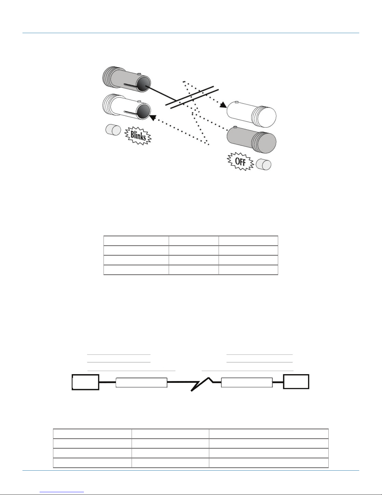
FiberAlert
FiberAlert minimizes the problems associated with the loss of one strand of fiber. If a strand is unavailable, the media converter
at the receiver end notes the loss of link. The device will then stop transmitting data and the link signal until a signal or link pulse
is received. The result is that the link LED on BOTH sides of the fiber connection will go out indicating a fault somewhere in the
fiber loop. Using FiberAlert, a local site administrator is notified of a fault and can quickly determine where a cable fault is located.
NOTE: Enable FiberAlert on ONE side of a media conversion only; enabling it on both sides will keep both transmitters off
indefinitely.
Local site
XMT
RCV
Remote site
RCV
LED
LED OFF = Broken link
Figure 3-3. Product with FiberAlert enabled. Remote site stops transmitting, local link LED blinks,
Pulsing FiberAlert
Pulsing FiberAlert minimizes the problems associated with the loss of one strand of fiber. If a strand is unavailable, the device at
the receiver end notes the loss of link. The device will stop transmitting data and start sending link pulses. Until a valid link is
received, the fiber link LED will be OFF on the device on the receiver side of the fiber strand with the fault while the fiber Link LED
on the other unit will blink. Pulsing FiberAlert notifies a local site administrator of a fault, allowing quick determination of where a
cable fault resides.
NOTE: Pulsing FiberAlert can be enabled on BOTH sides of a conversion.
indicating a break in the fiber loop.
877-877-2269 | blackbox.com
XMT
LED
Pa g e 11
Page 12
Chapter 3: Configuration
Local site
XMT
RCV
LED
Cable break
Remote site
RCV
XMT
LED
Figure 3-4. Product with Pulsing FiberAlert enabled. Remote site stops transmitting, Local Link LED blinks,
indicating a break in the fiber loop.
Auto Negotiation
The following chart states the availability of the Auto Negotiation feature on media conversion modules.
Table 3-2. Autonegotiation product comparison.
Module Feature Availability
10 Mbps modules Autonegotiation N/A
100 Mbps modules Autonegotiation DIP switch selectable
10/10 0 Mbps modules Autonegotiation Always Enabled
Auto Negotiation on 100 Mbps, 10/100 Mbps Modules
When autonegotiation is enabled, the media converter negotiates as a 100 Mbps full-duplex device; if the device the media converter is connected to can operate at 100 Mbps full-duplex, a link will be established. If the twisted pair port on the other device
does not have the ability to autonegotiate, or if a 100 Mbps half-duplex connection is desired, autonegotiation on the media converter must be disabled. Half- and full-duplex settings must be manually set and match on both end devices to which the media
converters are connected. The diagram below shows a typical application, followed by a table with three possible configurations.
HDX
FDX
HDX
Switch Switch
Media Converter Media Converter
OK (Manual setting only)
OK (AutoManual setting only)
WRONG
HDX
FDX
HDX
Figure 3-5. Autonegotiation application.
Table 3-3. Auto Negotiation flow control settings.
End-to-end connection End Device Media Converter
Half-duplex Manually configure HDX Auto Negotiation OFF
Full-duplex Manually configure FDX Auto Negotiation OFF
Full-duplex Auto Negotiation ON Auto Negotiation ON
Page 12
877-877-2269 | blackbox.com
Page 13
Chapter 4: Installation
4. Installation
4.1 Installing Media Converter Modules
The media conversion modules can be installed in any available slot in a media converter chassis. Media conversion modules are
hot-swappable.
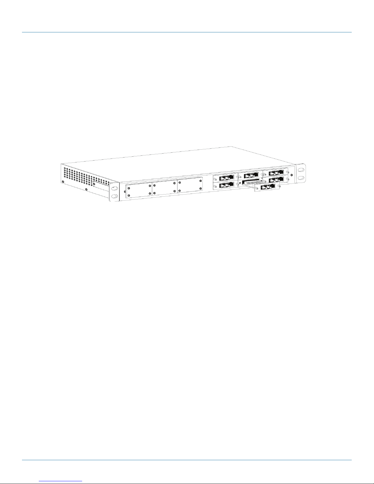
Media conversion modules include screws on the faceplate for securing them to the media converter chassis. To install a module,
simply unscrew the blank bracket converting the slot where the module is installed. Slide the module into the chassis, via the card
guides, until the module is seated securely in the connector. Hand-tighten the thumb screw until snug. Finish tightening the
thumb screw using a screw driver, being careful to not over-tighten.
Figure 4-1. Installing module in chassis.
NOTE: Media converter chassis ship with all but one media conversion module slot covered with “blank” brackets. Be sure to keep
unused slots covered for EMI containment. Save any “blanks” removed during installation for future use if configuration
requirements change.
Installation Tip: Since single-strand fiber products use optics that transmit and receive on two different wavelengths,
the single-strand fiber products must be deployed in pairs, or connect two compatible media converter
single-strand fiber products. For example, connect Compact Media Converter, TX/SSFX-SM1310-SC (which has
1310 xmt and 1550 rcv) to a product which has 1550 xmt and 1310 rcv, e.g. 100 Mbps TX/SSFX-SM1550-SC
Module. The two connected products must also have the same speed and distance capabilities (i.e. both are single-mode [20 km] or both are single/PLUS [40 km]).
4.2 Installing a Power Supply
When installing a redundant power supply module into a powered-on 12-Slot chassis, we recommend setting the ON/OFF switch
on the module (if present) to OFF. After installing the power supply, turn its switch ON.
If the redundant power supply module does NOT have an ON/OFF switch, we recommend powering-down the chassis before
installing the power supply. Turn the chassis back ON after installing the power supply.
877-877-2269 | blackbox.com
Page 13
Page 14

Chapter 5: LED Operation
5. LED Operation
Each media conversion module features diagnostic LEDs (see diagrams below) that provide information on features and ports.
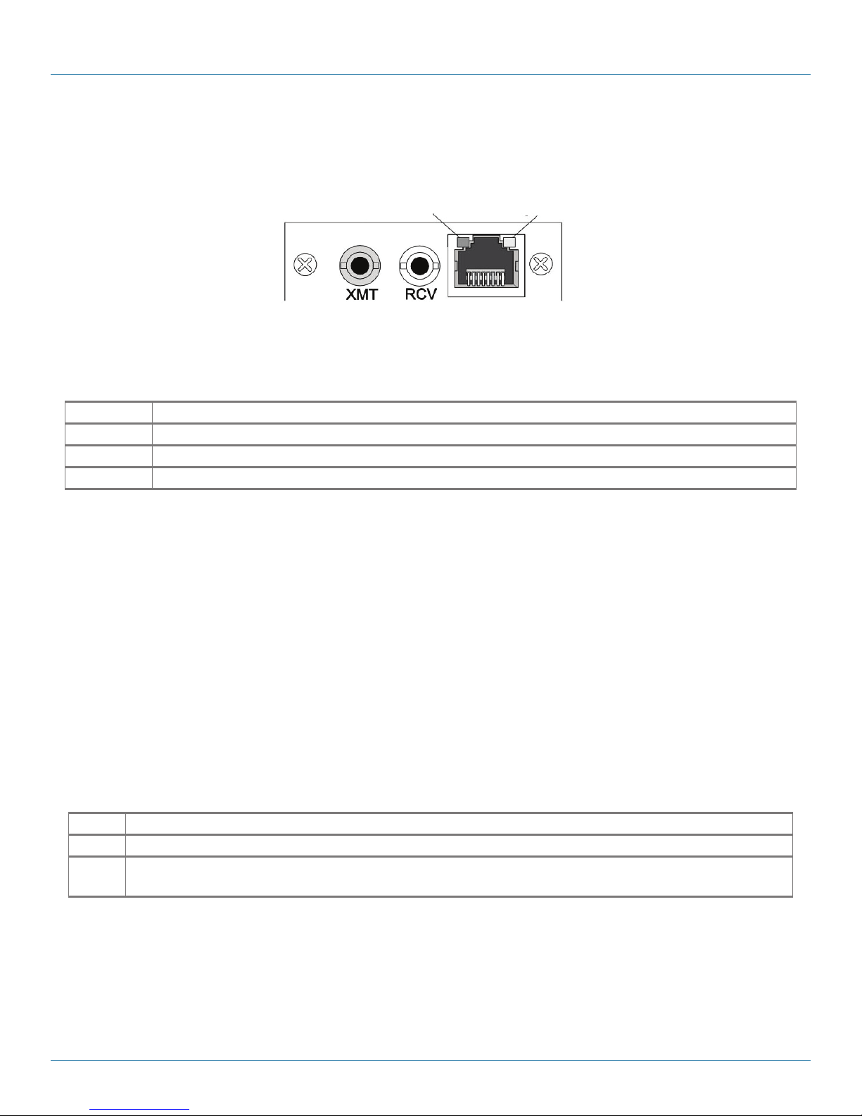
LEDs on port interface module TP/FO
The LED functions for port interface module TP/FO with fiber ports are as follows.
Fiber Activity/
FiberAlert LED
Twisted Pair (TP)
Link LED
Fiber (FO)
Link LED
Figure 5-1. LEDs on TP/FO port interface module.
Table 5-1. TP/FO port interface module LED functions.
LED Function
FO LINK Glows green when link is established on the fiber port.
FiberAlert Glows green when link is established on the fiber port.
TP Link Glows green when link is established on the TP port.
Activity Blinks amber when data is being passed on either port.
LEDs on port interface module TP/FO (10 Mbps)
The LED functions on the port interface module TP/FO are described in Table 5-2.
Fiber (FX)
Link/Activity LED
Twisted Pair (TX)
Link/Activity LED
Twisted Pair (TP)
Activity LED
Figure 5-2. LEDs on port interface module TP/FO.
Table 5-2. Port interface module TP/FO LED functions.
LED Function
FO Link/Act Glows green when link is established on the FO port; blinks green when activity is detected on the port.
TP Link/Act Glows amber when link is established on the TP port; blinks amber when activity is detected on the port.
Page 14
877-877-2269 | blackbox.com
Page 15

Chapter 5: LED Operation
LEDs on link interface module TP-TX/FX (10/100Mbps)
The LED functions on link interface module TP-TX/FX are described in Table 5-3.
Fiber (FX)
Link/Activity LED
Figure 5-3. Link interface module TP-TX/FX LEDs.
Table 5-3. Link interface module TP-TX/FX LED functions.
LED Function
FX Link/Act Glows green when link is established on the FX port; blinks green when activity is detected on the port.
TX Link/Act Glows green when link is established on the TP/TX port; blinks green when activity is detected on the port.
Twisted Pair (TX)
Link/Activity LED
LEDs on link interface module TX/FX and TX/SX
The LED functions on link interface module TX/FX are as follows.
Fiber (FX)
Activity LED
Fiber (FX)
Link LED
Figure 5-4. Link interface module TX /FX LEDs.
Table 5-4. Link interface module TX/FX LEDs functions.
LED Function
FX Link Glows green when link is established on the FX port.
FX Activity Glows amber if data is being passed on the FX port.
TX Pair Link Glows green if link is established on the TX port.
TX Activity Glows amber when data is being passed on the TX port.
Twisted Pair (TX)
Link LED
Twisted Pair (TX)
Activity LED
877-877-2269 | blackbox.com
Page 15
Page 16
Chapter 5: LED Operation
LEDs on Gigabit module
The LED functions on Gigabit and link interface TX/FX and TX/SX Modules are as follows.
Fiber (FX)
Link/Activity LED
Figure 5-5. Gigabit module LEDs.
Table 5-5. Gigabit module LED functions.
LED Function
FX Link/Act Glows green when link is established on the FX port; blinks green when activity is detected on the port.
TX Link/Act Glows amber when link is established on the TX port; blinks amber when activity is detected on the port.
Activity Glows green in normal operation.
Media Converter Series Chassis
The Media Converter Series Chassis are available in one, four, eight, and twelve slot chassis. The one, four, and eight chassis
include one power supply. The twelve slot chassis includes one power supply and has an available slot to purchase and populate a
second slot for redundant power.
Twisted Pair (TP)
Link/Activity LED
All modules, port interface, link interface 10/100 and Gigabit, can be installed in the chassis and in any combination.
LEDs on MediaConverter Chassis
4-Slot and 8-Slot chassis include LEDs on the back of the chassis. The LEDs will only light if a 10-Mbps port interface module is
installed. All modules offer port interface LEDs for link and activity; do not rely on the chassis LEDs other than the power LED.
LEDs on Power Supplies
Power supplies include the following LEDs.
Table 5-6. Power supply LEDs functions.
LED Function
Power Glows green when chassis has power.
Activity This LED blinks green when data is being passed on either port of a module that does not include Link/Activity
LEDs; applicable to modules only.
Page 16
877-877-2269 | blackbox.com
Page 17

Chapter 6: Troubleshooting
6. Troubleshooting
The following information assists in troubleshooting the Modular Media Converters:
• During installation, first test the fiber and twisted pair connections with all troubleshooting features disabled, then enable these
features, if desired, just before final installation. This will reduce the features’ interference with testing.
• When working with units where the features cannot be connected, establish BOTH the twisted pair and fiber connections in
order to establish link LEDs.
• To test a media converter by itself, have an appropriate fiber patch cable, then follow these steps to test:
1. Connect the media converter to the twisted pair device with a twisted pair cable.
2. Loop a single strand of fiber from the transmit port to the receive port of the media converter.
3. Verify that both the twisted pair and the fiber link LEDs (see LEDs, below) on the media converter are on.
NOTE: Use caution when conducting a loopback test; it is possible to create a network loop if connecting the twisted pair port to
an active network switch. We recommend connecting the twisted-pair cable to a PC for this type of test.
• Use the appropriate twisted pair cable, and have the crossover/straight-through switch set correctly if the media converter does
not include AutoCross.
• If using a high powered device (which is designed for long distance installations) for a short distance installation, the fiber
transmitters may overdrive the receivers and cause data loss. In this case, you may need to add an optical attenuator to the
connection.
Rackmount Instructions
Elevated Operating
Ambient
Reduced Air Flow When you install the equipment in a rack, make sure that the amount of air flow required
Circuit Overloading When you connect the equipment to the supply circuit, make sure you do not overload
Reliable Grounding Be sure to ground rackmounted equipment properly. Pay attention to supply connections
If installed in a closed or multi-unit rack assembly, the operating ambient temperature of
the rack environment may be greater than room ambient. Install the equipment in an
environment compatible with the maximum ambient temperature (Tma) specified by the
ma nufac ture r.
for safe operation of the equipment is not compromised.
circuits. This might affect over current protection and supply wiring. Consider equipment
nameplate ratings.
other than direct connections to the branch circuit (e.g., using power strips).
877-877-2269 | blackbox.com
Page 17
Page 18

Appendix A: Fiber Optic Cleaning Guidelines
Appendix A. Fiber Optic Cleaning Guidelines
Fiber Optic transmitters and receivers are extremely susceptible to contamination by particles of dirt or dust, which can obstruct
the optic path and cause performance degradation. Good system performance requires clean optics and connector ferrules.
1. Use fiber patch cords (or connectors, if you terminate your own fiber) only from a reputable supplier; low-quality components
can cause many hard-to-diagnose problems in an installation.
2. Dust caps are installed at Black Box to ensure factory-clean optical devices. Do not remove these protective caps until you
connect the fiber cable to the device. If you need to disconnect the fiber device, reinstall the protective dust caps.
3. Store spare caps in a dust-free environment such as a sealed plastic bag or box so that when reinstalled they do not introduce
any contamination to the optics.
4. If you suspect that the optics have been contaminated, alternate between blasting with clean, dry, compressed air and flushing
with methanol to remove particles of dirt.
Page 18
877-877-2269 | blackbox.com
Page 19

Appendix B: Electrostatic Discharge Precautions
Appendix B. Electrostatic Discharge Precautions
Electrostatic discharge (ESD) can cause damage to any product, add-in modules or standalone units, containing electronic components. Always observe the following precautions when installing or handling these kinds of products
1. Do not remove unit from its protective packaging until ready to install.
2. Wear an ESD wrist grounding strap before handling any module or component. If the wrist strap is not available, maintain
grounded contact with the system unit throughout any procedure requiring ESD protection.
3. Hold the units by the edges; do not touch the electronic components or gold connectors.
4. After removal, always place the boards on a grounded, static-free surface, ESD pad, or in a proper ESD bag. Do not slide the
modules or chassis over any surface.
CAUTION: Integrated circuits and fiber optic components are extremely susceptible to electrostatic discharge damage. Do not
handle these components directly unless you are a qualified service technician and use tools and techniques that conform to accepted industry practices.
UL/CUL: Listed to Safety of Information Technology Equipment, including Electrical Business Equipment.
CE: The products described herein comply with the Council Directive on Electromagnetic Compatibility (2004/108/EC) and the
Council Directive on Electrical Equipment Designed for use within Certain Voltage Limits (2006/95/EC). Certified to Safety of
Information Technology Equipment, Including Electrical Business Equipment. For further details, contact Black Box Technical
Support at 877-877-2269 or info@blackbox.com.
European Directive 2002/96/EC (WEEE) requires that any equipment that bears this symbol on product or packaging must not
be disposed of with unsorted municipal waste. This symbol indicates that the equipment should be disposed of separately from
regular household waste. It is the consumer’s responsibility to dispose of this and all equipment so marked through designated
collection facilities appointed by government or local authorities. Following these steps through proper disposal and recycling will
help prevent potential negative consequences to the environment and human health. For more detailed information about proper
disposal, contact local authorities, waste disposal services, or the point of purchase for this equipment.
877-877-2269 | blackbox.com
Page 19
Page 20

Black Box Tech Support: FREE! Live. 24/7.
Tech support the
way it should be.
Great tech support is just 60 seconds away at 877-877-2269 or blackbox.com.
About Black Box
Black Box provides an extensive range of networking and infrastructure products. You’ll find everything from cabinets and racks
and power and surge protection products to media converters and Ethernet switches all supported by free, live 24/7 Tech support
available in 60 seconds or less.
© Copyright 2016. Black Box Corporation. All rights reserved. Black Box® and the Double Diamond logo are registered trademarks of BB Technologies, Inc.
Any third-party trademarks appearing in this manual are acknowledged to be the property of their respective owners.
le7401a-r2_rev2 User Manual
877-877-2269 | blackbox.com
 Loading...