

Page 1
CUSTOMER
SUPPORT
INFORMATION
To order or for technical support: Call 724-746-5500 or fax 724-746-0746
Technical support and fax orders 24 hours a day, 7 days a week
Phone orders 24 hours, 7 A.M. Monday to midnight Friday; Saturday 8 to 4 (Eastern)
Mail order: Black Box Corporation, 1000 Park Drive, Lawrence, PA 15055-1018
DECEMBER 1998
LE601A-R3 LE620A LE629A
LE602A-R3 LE622A LE630A
LE603A-R5 LE624A LE631A
LE604A-R4 LE626A LE632A
LE605A-R3 LE628A LE633A
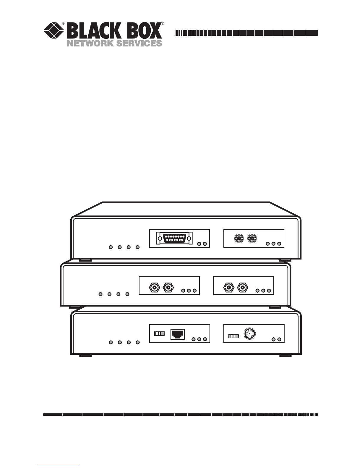
Local and Remote Repeaters
JABCOLRXPWR
Local Repeater
PART
RX
EXT
INT
LINK
PART
RX
JABCOLRXPWR
Remote Repeater-SM
LINK
PART
RX
TX
RX
LINK
PART
RX
TX
RX
JABCOLRXPWR
Remote Repeater
LINK
PART
RX
PART
RX
Page 2

FCC AND DOC/MDC STATEMENTS
3
FEDERAL COMMUNICATIONS COMMISSION
AND
INDUSTRY CANADA
RADIO FREQUENCY INTERFERENCE STATEMENTS
This equipment generates, uses, and can radiate radio frequency
energy and if not installed and used properly, that is, in strict
accordance with the manufacturer’s instructions, may cause
interference to radio communication. It has been tested and found
to comply with the limits for a Class A computing device in
accordance with the specifications in Subpart J of Part 15 of FCC
rules, which are designed to provide reasonable protection against
such interference when the equipment is operated in a commercial
environment. Operation of this equipment in a residential area is
likely to cause interference, in which case the user at his own
expense will be required to take whatever measures may be
necessary to correct the interference.
Changes or modifications not expressly approved by the party
responsible for compliance could void the user’s authority to
operate the equipment.
This digital apparatus does not exceed the Class A limits for radio noise
emission from digital apparatus set out in the Radio Interference
Regulation of Industry Canada.
Le présent appareil numérique n’émet pas de bruits radioélectriques
dépassant les limites applicables aux appareils numériques de
classe A prescrites dans le Règlement sur le brouillage radioélectrique
publié par Industrie Canada.
TRADEMARK USED IN THIS MANUAL
ST is a registered trademark of AT&T.
Any other trademarks mentioned in this manual are acknowledged
to be the property of the trademark owners.
Page 3

LOCAL AND REMOTE REPEATERS
NORMAS OFICIALES MEXICANAS (NOM) ELECTRICAL SAFETY STATEMENT
INSTRUCCIONES DE SEGURIDAD
1. Todas las instrucciones de seguridad y operación deberán ser leídas antes
de que el aparato eléctrico sea operado.
2. Las instrucciones de seguridad y operación deberán ser guardadas para
referencia futura.
3. Todas las advertencias en el aparato eléctrico y en sus instrucciones de
operación deben ser respetadas.
4. Todas las instrucciones de operación y uso deben ser seguidas.
5. El aparato eléctrico no deberá ser usado cerca del agua—por ejemplo,
cerca de la tina de baño, lavabo, sótano mojado o cerca de una alberca,
etc.
6. El aparato eléctrico debe ser usado únicamente con carritos o pedestales
que sean recomendados por el fabricante.
7. El aparato eléctrico debe ser montado a la pared o al techo sólo como
sea recomendado por el fabricante.
8. Servicio—El usuario no debe intentar dar servicio al equipo eléctrico más
allá a lo descrito en las instrucciones de operación. Todo otro servicio
deberá ser referido a personal de servicio calificado.
9. El aparato eléctrico debe ser situado de tal manera que su posición no
interfiera su uso. La colocación del aparato eléctrico sobre una cama,
sofá, alfombra o superficie similar puede bloquea la ventilación, no se
debe colocar en libreros o gabinetes que impidan el flujo de aire por los
orificios de ventilación.
10. El equipo eléctrico deber ser situado fuera del alcance de fuentes de
calor como radiadores, registros de calor, estufas u otros aparatos
(incluyendo amplificadores) que producen calor.
11. El aparato eléctrico deberá ser connectado a una fuente de poder sólo
del tipo descrito en el instructivo de operación, o como se indique en el
aparato.
4
Page 4

NOM STATEMENT
12. Precaución debe ser tomada de tal manera que la tierra fisica y la
polarización del equipo no sea eliminada.
13. Los cables de la fuente de poder deben ser guiados de tal manera que no
sean pisados ni pellizcados por objetos colocados sobre o contra ellos,
poniendo particular atención a los contactos y receptáculos donde salen
del aparato.
14. El equipo eléctrico debe ser limpiado únicamente de acuerdo a las
recomendaciones del fabricante.
15. En caso de existir, una antena externa deberá ser localizada lejos de las
lineas de energia.
16. El cable de corriente deberá ser desconectado del cuando el equipo no
sea usado por un largo periodo de tiempo.
17. Cuidado debe ser tomado de tal manera que objectos liquidos no sean
derramados sobre la cubierta u orificios de ventilación.
18. Servicio por personal calificado deberá ser provisto cuando:
A: El cable de poder o el contacto ha sido dañado; u
B: Objectos han caído o líquido ha sido derramado dentro del
aparato; o
C: El aparato ha sido expuesto a la lluvia; o
D: El aparato parece no operar normalmente o muestra un cambio en
su desempeño; o
E: El aparato ha sido tirado o su cubierta ha sido dañada.
5
Page 5

LOCAL AND REMOTE REPEATERS
Contents
Chapter Page
1. Specifications ............................................................................................. 7
2. Introduction ............................................................................................. 10
2.1 Unpacking and Inspecting the Repeater ........................................ 10
2.2 What the Repeater Does ................................................................... 11
2.3 Different Kinds of Ports .................................................................... 12
2.3.1 BNC ........................................................................................... 12
2.3.2 AUI ............................................................................................ 13
2.3.3 10BASE-T .................................................................................. 15
2.3.4 Multimode or Single-Mode Fiber ST ...................................... 16
3. Installation ................................................................................................ 19
3.1 Where to Put the Repeater ............................................................... 19
3.2 Connecting Ethernet Media ............................................................. 20
3.2.1 Thin Coaxial Connections ...................................................... 20
3.2.2 AUI Connections ..................................................................... 20
3.2.3 Twisted-Pair Connections ........................................................ 21
3.2.4 Multimode or Single-Mode Fiber Connections ..................... 21
4. Operation ................................................................................................. 22
4.1 How the Repeater Works .................................................................. 22
4.2 Powering Up the Repeater ............................................................... 23
4.3 Interpreting the Main LED Indicators ............................................ 23
5. Troubleshooting ...................................................................................... 24
5.1 Things to Try First ............................................................................. 24
5.2 Calling Your Supplier ....................................................................... 25
5.3 Shipping and Packaging ................................................................... 25
6
Page 6

7
CHAPTER 1: Specifications
Compliance — FCC Class A, DOC Class/MDC classe A
Standards — IEEE 802.3, Ethernet Ver. 1 and 2
The Repeater models all have two front-mounted ports. The types of ports on
each model determine the types of Interfaces each model supports, the types
of Cable Required, the Maximum Distance attainable, and which (if any)
User Controls, Indicators, and Connectors are on each model (see below).
Ports — LE601A-R3: (2) AUI;
LE602A-R3: (2) BNC;
LE603A-R5: (1) AUI, (1) Multimode Fiber ST;
LE604A-R4: (1) BNC, (1) Multimode Fiber ST;
LE605A-R3: (1) AUI, (1) BNC;
LE620A: (1) BNC, (1) 10BASE-T;
LE622A: (1) AUI, (1) 10BASE-T;
LE624A: (2) 10BASE-T;
LE626A: (1) 10-BASE-T, (1) Multimode Fiber ST;
LE628A: (2) Multimode Fiber ST;
LE629A: (1) AUI, (1) Single-Mode Fiber ST;
LE630A: (1) BNC, (1) Single-Mode Fiber ST;
LE631A: (1) 10BASE-T, (1) Single-Mode Fiber ST;
LE632A: (1) Multimode Fiber ST, (1) Single-Mode
Fiber ST;
LE633A: (2) Single-Mode Fiber ST
Interfaces — For each AUI port: 10BASE5 (AUI);
For each BNC port: 10BASE2;
For each 10BASE-T port: 10BASE-T;
For each Multimode Fiber ST port: 10BASE-FL,
FOIRL;
For each Single-Mode Fiber ST port: Single-mode
fiberoptic Ethernet
1. Specifications
Page 7

8
LOCAL AND REMOTE REPEATERS
Cable Required — For AUI ports: AUI transceiver (drop, patch) cable;
For BNC ports: RG58 coaxial;
For 10BASE-T ports: Straight-through-pinned
shielded or unshielded twisted-pair;
For Multimode Fiber ST ports: 62.5-µm core, 125-µm
cladding multimode fiberoptic;
For Single-Mode Fiber ST ports: 9-µm core, 125-µm
cladding single-mode fiberoptic
Maximum Distance
(Segment Length) — For segments attached to:
AUI ports: 500 m (1640.4 ft.) of Thick Ethernet
backbone (but not more than 50 m [164 ft.] of
AUI cable from Repeater to backbone);
BNC ports: 185 m (607 ft.) of Thin Ethernet
cable;
10BASE-T ports: 100 m (328.1 ft.) of twisted-pair
cable;
Multimode Fiber ST ports:
1 km (3280.8 ft., 0.6 mi.) of multimode fiberoptic
cable if segment is FOIRL;
2 km (6561.7 ft., 1.2 mi.) of multimode fiberoptic
cable if segment is 10BASE-FL;
Single-Mode Fiber ST ports: 10 km (32,808.4 ft.,
6.2 mi.) of single-mode fiberoptic cable
Data Rate — 10 Mbps
Error Handling — Each port automatically partitions its connected
segment after detecting 32 consecutive collisions on
that segment; automatically reconnects partitioned
segment after receiving 512 consecutive error-free
bits from that segment
User Controls — On each BNC port: (1) Slide switch to enable/disable
internal termination;
On each 10BASE-T port: (1) Slide switch to enable/
disable straight-through interrepeater cabling
Page 8

9
CHAPTER 1: Specifications
Indicators — All models (on main chassis): (4) LEDs: PWR (power),
RX (receive), COL (collision), JAB (jabber);
On each port (all types): (2) LEDs: PART (partitioned)
and RX (receive);
On each 10BASE-T or Fiber ST port: (1) LINK LED
Connectors — All models (on main chassis): (1) Rear-mounted
IEC 320 male power inlet;
On each AUI port: (1) DB15 female;
On each BNC port: (1) BNC female;
On each 10BASE-T port: (1) Shielded RJ-45 female;
On each Multimode Fiber ST port: (2) Multimode
ST female ([1] TX, [1] RX);
On each Single-Mode Fiber ST port: (2) Single-mode
ST female ([1] TX, [1] RX)
Power — Input: 90 to 260 VAC, 47 to 63 Hz into internal
autosensing power supply (6-ft. [1.8-m] power cord
with NEMA 5-15P plug and IEC 320 female outlet
included with shipments to 115-VAC regions only);
Consumption: 15 watts maximum
MTBF — 40,000 hours
Cooling Method — Convection
Temperature
Tolerance — Operating: 32 to 122˚ F (0 to 50˚ C)
Storage: –4 to 140˚ F (–20 to 60˚ C)
Humidity
Tolerance — 10 to 95% noncondensing
Size — 1.8"H x 8.5"W x 5.4"D (4.6 x 21.6 x 13.7 cm)
Weight — 2.5 lb. (1.1 kg)
Page 9

10
LOCAL AND REMOTE REPEATERS
The Local and Remote Repeaters expand a network by extending individual
Ethernet segments. They’re ideal when you need to go beyond the standard
distance limits, or where you need to bring two different media together in
one Ethernet link.
Every Repeater model comes ready to plug in. It’s easy to install on a shelf
in your wiring closet, vertically on the wall, or on a desktop. The media
connectors and the status LEDs are all on the front panel, where they’re easy
to get at.
Local and Remote Repeaters meet all the IEEE 802.3 and Ethernet
Ver. 1.0 and 2.0 specifications for repeaters. They work either as
homogeneous-media repeaters (repeaters that connect two segments of the
same medium) or mixed-media repeaters (repeaters that connect segments of
two different media).
2.1 Unpacking and Inspecting the Repeater
Before you install the Repeater, examine the shipping container for obvious
damage. If you see any damage that seems to have occurred during shipment
or delivery, notify the carrier.
Next, inspect the contents of the package. Make sure that there is no
apparent damage, and make sure you’ve received all these items:
• (1) Repeater. The unit should look something like this (although the
ports might be different):
• (1) Copy of this manual.
•[If your local power is 115 VAC,] (1) AC power cord.
Take everything out of the carton. We recommend that you keep the shipping
container and the packing materials in case you ever have to ship the
Repeater.
If anything is missing or damaged, call Black Box at once. If you need to
return the Repeater, see Chapter 5 for instructions.
JABCOLRXPWR
Local Repeater
PART
RX
EXT
INT
PART
RX
EXT
INT
2. Introduction
Page 10

11
CHAPTER 2: Introduction
2.2 What the Repeater Does
The Local and Remote Repeaters work as in-line repeaters. Each repeater has
two ports, and each port can connect to one segment of one type of Ethernet
medium: 10BASE2, 10BASE5, 10BASE-FL, 10BASE-T, FOIRL, or single-mode.
Since the Repeaters have full 802.3 repeater functionality, each port can
support a full-length segment. Each kind of port has a single media-interface
connector (see Fig. 2-1 below).
Fig. 2-1. The Repeaters’ port types.
To simplify connections, each port is accessible from the front of the
Repeater. All the LEDs are on the front panel as well. You never need access
to the rear of the Repeater except to attach its AC power cord.
The Repeaters’ internal power supply is autosensing; it can handle any type
of AC power normally available worldwide. The power input can range from
90 to 260 VAC at 47 to 60 Hz. (If your local power is 115 VAC, we supply the
power cord; otherwise, you must supply your own.) The Repeater is
convection-cooled, so you won’t hear any fan noise.
Besides the LEDs on each port, there are four status LEDs on the chassis:
Power (PWR), Receive (RX), Collision (COL), and Jabber (JAB). Refer to
Section 4.3 for more information about these LEDs.
JABCOLRXPWR
Local Repeater
PART
RX
EXT
INT
PART
RX
EXT
INT
AUIBNC
10BASE-T
Multimode or
Single-Mode
Fiber ST
Page 11

12
LOCAL AND REMOTE REPEATERS
2.3 Different Kinds of Ports
Your Local or Remote Repeater comes with two ports. They might be any
combination of the available port types; the Repeater’s modular design means
we can offer it for any combination of media.
Each port has at least two LEDs: PART (Partition) and RX (Receive). PART
flashes yellow to indicate that the segment has been partitioned. (The
Repeater partitions a segment automatically when there is jabber on that
segment.) RX flashes green intermittently to show that the Repeater is
receiving data. In addition, each 10BASE-T port and each Fiber ST port has a
LINK LED that lights steadily to show that the cable running from the port to
the device at the other end is properly connected.
2.3.1 BNC
For those Repeaters that have any, each BNC port has a standard BNC female
connector for 10BASE2 (“Thin Ethernet” or “ThinNet”) applications. This is
what a Repeater’s BNC port looks like:
If your Repeater is at the end of a segment, you can use its special switchselectable internal terminator instead of the normally mandatory external
T-connector and terminator. To use the internal terminator, slide the switch
to the “INT” position (toward the right). If your Repeater isn’t at the end of
the segment, make sure you disable the internal terminator by sliding the
switch to the “EXT” position (toward the left). Remember:
• INT (right)—terminated internally
• EXT (left)—T-connector and external termination needed
PART
RX
EXT
INT
Page 12

13
CHAPTER 2: Introduction
2.3.2 AUI
For those Repeaters that have any, each AUI port has a DB15 female AUI
connector and slide lock for standard 10BASE5 (“Thick Ethernet” or
“Thicknet”) applications. You’ll need a transceiver with no SQE test (or SQE
test disabled) to connect it to a standard Ethernet segment. This is what a
Repeater’s AUI port looks like:
You can also connect Ethernet devices to the AUI port with standard AUI
cabling. If you do, it is important to consider the length of the AUI segment
or the distance to the attached device. The maximum transmission distance
between an AUI port and a backbone transceiver with an AUI connector will
vary:
• When an AUI cable connects the AUI port directly to a backbone
transceiver, the maximum AUI segment length is 50 m (165 ft.).
• If the AUI port is connected to a transceiver that has been cascaded from
another transceiver, the maximum AUI segment length is reduced by 6 m
(20 ft.) for every additional level of network transceiver cascaded from the
original backbone transceiver’s tap.
The AUI connector supports all the standard IEEE 802.3 signals listed in
Table 2-1 on the next page.
PART
RX
Page 13

14
LOCAL AND REMOTE REPEATERS
Table 2-1. AUI Pin Assignments
Pin Function
1 Control In Circuit Shield
2 Control In Circuit A
3 Data Out Circuit A
4 Data In Circuit Shield
1
5 Data In Circuit A
6 Voltage Common
2
7 Control Out Circuit A
8 Control Out Circuit Shield (conductive shell)
1
9 Control In Circuit B
10 Data Out Circuit B
11 Data Out Circuit Shield
®
12 Data In Circuit B
13 Voltage Plus (+)
2
14 Voltage Shield
1
15 Control Out Circuit B
Shell Protective Ground
1
Pins 4, 8, 11, and 14 may be connected to Pin 1.
2
Voltage Plus (Pin 13) and Voltage Common (Pin 6) use a
single twisted pair in the AUI cable.
Page 14

15
CHAPTER 2: Introduction
2.3.3 10BASE-T
For those Repeaters that have any, each 10BASE-T port has an RJ-45 female
connector for attaching twisted-pair Ethernet segments of any standard
length. The connector is shielded to minimize emissions, but you can connect
to it either unshielded twisted-pair (UTP) or shielded twisted-pair (STP)
segments of new or existing 10BASE-T networks. This is what a Repeater’s
10BASE-T port looks like:
If you want to connect your Local or Remote Repeater to another Ethernet
repeater or to a hub, you don’t need a special crossover cable. Just set the
Repeater’s Media-Dependent Interface—Crossover (MDI-X) switch:
• For cascaded and uplink connections (connections to hubs,
concentrators, or other repeaters), set the MDI-X switch in the Up (left)
position.
• For segments that go to workstations and other user devices, set the MDIX switch in the Down (right) position.
When the MDI-X switch is set Down, the Repeater’s RJ-45 connector is pinned
normally (to support standard “hub-to-user” runs of straight-through-pinned
twisted-pair cable):
• Pin 1 = Receive +
• Pin 2 = Receive –
• Pin 3 = Transmit +
• Pin 6 = Transmit –
• The other pins are not used.
LINK
PART
RX
Page 15

16
LOCAL AND REMOTE REPEATERS
When the MDI-X switch is set Up, the transmit and receive pairs of the
Repeater’s RJ-45 connector are exchanged so that it can support “uplink” or
“hub-to-hub” connections using straight-through-pinned twisted-pair cable:
• 1 = Transmit +
• 2=Transmit –
• 3=Receive +
• 6=Receive –
• The other pins are not used.
The Repeater’s 10BASE-T port supports UTP wiring with maximum segment
lengths of up to 100 m (328.1 ft.), or STP wiring with maximum segment
lengths of up to 150 m (492.1 ft.) You don’t need an external transceiver; the
transceiver circuitry is built into the port.
2.3.4 M
ULTIMODE ORSINGLE-MODEFIBER
ST
For those Repeaters that have any, each Multimode or Single-Mode Fiber ST
port has two standard ST®female connectors (one TX, one RX) for fiberoptic
Ethernet applications. This is what Repeaters’ Multimode (above) and SingleMode (below) Fiber ST ports look like:
As you can see, the only way to tell the two port types apart is the “Sgl. M.”
label that appears on the Single-Mode ports but not on the Multimode ports.
The Multimode Fiber ST ports support 10BASE-FL applications and are
backward-compatible with FOIRL equipment. The Single-Mode Fiber ST
ports support most standard single-mode Ethernet applications.
LINK
PART
RX
TX
RX
Sgl. M.
LINK
PART
RX
TX
RX
Page 16

17
CHAPTER 2: Introduction
NOTE
The Multimode Fiber ST circuit board contains a six-pin jumper that
controls the intensity of the transmitted signal. By default, the jumper is
placed across pins 1 and 2. The jumper may be set as shown below, to
accommodate distances of up to 4 km.
When distances of less than 2 km are needed, the jumper should be placed
across pins 1 and 2.
Jumper Across Distances Supported
1–2 0–2 km
3–4 0.5–3 km*
5–6 1.5–4 km*
*When fiber cable distances of more than 2 km are selected, the minimum
cable length must also be increased, as shown in the table above.
5 6
3 4
1 2
J1
Default
Page 17

18
LOCAL AND REMOTE REPEATERS
NOTE
The Single-Mode Fiber ST circuit board contains a six-pin jumper, but the
jumper is only to be placed across pins 5 and 6. The others are not used.
Jumper Across Distances Supported
1–2 Not used
3–4 Not used
5–6 0-10 km
Be sure to use single-mode fiberoptic cable with this module. Single-mode
fiber has a smaller diameter than multi-mode fiber (2/15–8/60 microns for
single-mode, 50/125 or 62.5/125 microns for multimode, where xx/xx are
the diameters of the core and the core plus the cladding respectively).
5 6
3 4
1 2
J1
Default
Page 18

19
CHAPTER 3: Installation
3.1 Where to Put the Repeater
Where you put your Local or Remote Repeater will depend on the physical
layout of the network and the area to be served. Set up the Repeater in a cool,
dry place with easy access to all network connections you plan to make, within
about six feet (1.8 m) of a working AC outlet. Also make sure there is enough
space around the Repeater for air to circulate, because the unit has no fan
and relies on convection for its cooling.
The Repeater’s case is suitable for an ordinary workplace setting, but it’s
also rugged enough for a wiring closet. If you want to set the Repeater on a
desk, its four rubber feet will keep its case from scratching the desk’s finish.
You can even stack Repeaters, because the cases are strong enough to support
a stack many units high. This is especially useful in a cramped wiring closet.
NOTE
We do not recommend stacking units in a free-standing column. Make
sure your units are adequately supported.
If you want to mount the Repeaters in a rack, two of them will fit side by side
in a standard 19-inch (48.3-cm) equipment rack. Rackmounting hardware is
not included; you might want to order one of our rackmount shelves
(product code RM001) to mount them in.
You can also mount the Repeater vertically on a wall using wallmount
brackets—it works just as well vertically as horizontally. (Call for technical
support for information on where to purchase wallmount brackets.)
3. Installation
Page 19

20
LOCAL AND REMOTE REPEATERS
3.2 Connecting Ethernet Media
Depending on which model you ordered, your Repeater might have ports for
any combination of the standard Ethernet media. Follow the directions in the
appropriate subsection(s) below for the kinds of connections you need to
make.
3.2.1 T
HINCOAXIALCONNECTIONS
If your Repeater is at the end of a Thin Ethernet segment, plug the Thin
Ethernet cable directly into the Repeater’s BNC connector. You don’t need a
T-connector or an external terminator; just set the Repeater’s termination
switch to enable internal termination (see Section 2.3.1).
If the Repeater isn’t at the end of a Thin Ethernet segment, connect the
Thin Ethernet cables to the Repeater the same way you would connect it to
any other node: Plug the “leg” of a T-connector into the Repeater’s BNC
connector, then plug the cables leading to the previous node and the next
node into the “arms” of the T-connector. You must also set the Repeater’s
termination switch to disable internal termination (see Section 2.3.1).
3.2.2 AUI C
ONNECTIONS
You can attach your Repeater to a Thick Ethernet segment with a standard
AUI drop cable:
1. Plug the male end of the cable into the Repeater’s female AUI
connector.
2. Engage the slide lock on the AUI connector to make sure the cable
connection is secure.
3. Connect the other end of the cable to a network AUI port (a backbone
transceiver, a hub or fanout with an AUI port, or an AUI port in a
concentrator).
You can also use standard AUI cables to connect the Repeater to other
Ethernet devices. Keep in mind the distance limits for AUI cabling—see
Section 2.3.2.
Page 20

21
CHAPTER 3: Installation
3.2.3 T
WISTED-PAIRCONNECTIONS
To connect the Repeater to a UTP and STP 10BASE-T segment, take these
steps:
1. Plug either end of a standard 10BASE-T cable into the Repeater’s female
RJ-45 (10BASE-T) connector.
2. Connect the other end of the cable to the 10BASE-T workstation, hub, or
other device.
Make sure the Repeater’s MDI-X switch is set correctly for your application
(see Section 2.3.3). Also, when you power up the Repeater (see Section 4.2),
check the LINK LED on each 10BASE-T port. If it is lit, the network cables
should be properly connected. If it isn’t lit, then probably either the MDI-X
switch is set incorrectly, the network cables aren’t securely connected, or the
network cables are pinned incorrectly; check these things.
3.2.4 M
ULTIMODE ORSINGLE-MODEFIBERCONNECTIONS
To connect the Repeater to a multimode 10BASE-FL or FOIRL segment or a
single-mode Ethernet segment, take these steps:
1. Remove the protective dust caps from the Repeater’s ST connectors. Set
them aside in a safe place.
2. Wipe the ends of the connectors clean with a soft cloth or lint-free lens
tissue dampened with alcohol. Make sure the connectors are clean and
dry before you connect fiberoptic cable to them.
3. Use one strand of your fiberoptic cable to connect the Repeater’s TX
(Transmit) port to the remote device’s RX (Receive) port. Use the
strand color-coded with bands at regular intervals first, to make sure you
don’t mix up the connections.
4. Use the cable’s other strand to connect the Repeater’s RX port to the
remote device’s TX port.
When you power up the Repeater (see Section 4.2), check the LINK LED on
each Fiber ST port. If it is lit, the network cables should be properly
connected. If it isn’t lit, the network cables are probably either crossed or not
securely connected; try again.
Page 21

22
LOCAL AND REMOTE REPEATERS
4.1 How the Repeater Works
The Local and Remote Repeaters work as mixed-media or homogeneous
Ethernet repeaters. Each model complies with IEEE 802.3 specifications and
supports one or two of the standard Ethernet interfaces (10BASE2, 10BASE5,
10BASE-T, 10BASE-FL, FOIRL, and single-mode). Each Repeater performs
these important communication tasks:
1. Repeater functions: Each port operates in conjunction with the
controller functions of the base unit as a fully compliant Ethernet
repeater. The whole Local or Remote Repeater counts as a single
network repeater.
2. Collision handling: When a collision is detected on either port of the
Repeater, a jam pattern is generated according to IEEE 802.3 repeater
rules and propagated out of both Repeater ports.
3. Partitioning and reconnection: The Repeater will automatically
“partition” (disconnect) any port if 64 consecutive collisions occur on
the segment attached to it, or after 6.5 ms of continuous transmission
(which means the port is jabbering). Network integrity is checked every
800 ms, and segments are reconnected after a 512-bit packet is
transmitted on the network without error.
4. Indicating link status: The Fiber ST and 10BASE-T ports indicate link
integrity for fiberoptic and twisted-pair segments. If a cable is broken, or
if the power is lost at any point on the segment, the LINK indicator on
the attached port will go out.
4. Operation
Page 22

23
CHAPTER 4: Operation
4.2 Powering Up the Repeater
The Repeaters’ internal power supply is universal—you can use it anywhere
the local AC power is between 90 and 260 volts at 47 to 63 Hz. Repeaters
shipped to the United States and Canada come with a 6-foot (1.8-m) power
cord; elsewhere, you supply your own cord.
First plug the power cord’s IEC 320 female outlet into the IEC 320 male
power inlet on the Repeater’s rear panel. Then plug the other end of the
cord into a working AC outlet; the Repeater will power up immediately. The
Repeater’s PWR LED should light (see the next section), and if the Repeater
has any 10BASE-T or Fiber ST ports, their LINK LEDs should light if the
network cables between those ports and the attached devices have been
connected properly.
To turn the Repeater off, just unplug its power cord. You don’t need to
unplug the Repeater when you’re making Ethernet connections; you can
connect segments of any type of medium while the power is on.
4.3 Interpreting the Main LED Indicators
Besides the LEDs on the ports (see Section 2.3), there are four LEDs on the
chassis of the Repeater:
• PWR lights green to indicate that the Repeater is receiving power.
• RX lights green when data is being received on either or both ports.
• COL lights yellow when a collision has occurred.
• JAB lights yellow when a jabber condition has occurred.
Page 23

24
LOCAL AND REMOTE REPEATERS
5.1 Things to Try First
Before you call for technical support, there are a few things you can check
yourself:
1. If you have trouble while you’re installing the Repeater, read
Chapter 3 of this manual again. Make sure all the components of the
network are interoperable.
2. Check the cables and connectors to make sure that they have been
properly connected, and that they haven’t been damaged during
installation.
3. Make sure the power cord is properly attached to each unit, and that it is
plugged into a working AC outlet. If the cord is connected and plugged
in, the PWR indicator should be lit.
4. If the problem seems to be in some other device, replace that device with
a known-good device. If the problem goes away, the device you replaced
was the cause of it.
5. If you’re still having trouble, call for technical support as directed in the
next section.
5. Troubleshooting
Page 24

25
CHAPTER 5: Troubleshooting
5.2 Calling Black Box
If you determine that your Repeater is malfunctioning, do not attempt to alter or
repair it. It contains no user-serviceable parts. Contact Black Box.
Before you do, make a record of the history of the problem. Black Box will
be able to provide more efficient and accurate assistance if you have a
complete description, including:
• the nature and duration of the problem.
• when the problem occurs.
• the components involved in the problem.
• any particular application that, when used, appears to create the problem
or make it worse.
5.3 Shipping and Packaging
If you need to transport or ship your Repeater:
• Package it carefully. We recommend that you use the original container.
• If you are shipping the Repeater for repair, make sure you include its
power cord if one was supplied with the unit. If you are returning the
Repeater, make sure you include everything you received with the unit.
Before you ship, contact Black Box to get a Return Materials
Authorization (RMA) number.
Page 25

NOTES
Page 26

1000 Park Drive • Lawrence, PA 15055-1018 • 724-746-5500 • Fax 724-746-0746
© Copyright 1998. Black Box Corporation. All rights reserved.
 Loading...