

Page 1

CUSTOMER
SUPPORT
INFORMATION
Order toll-free in the U.S.: Call 877-877-BBOX (outside U.S. call 724-746-5500)
FREE technical support 24 hours a day, 7 days a week: Call 724-746-5500 or fax 724-746-0746
Mailing address: Black Box Corporation, 1000 Park Drive, Lawrence, PA 15055-1018
Web site: www.blackbox.com • E-mail: info@blackbox.com
SEPTEMBER 1999
LE3700A-R2
Ethernet Print Server
10BASE-T
12V
#AUI
PARALLEL
SERIAL
PARALLEL
OK
NETWORK
PARALLEL
SERIAL
POWER
POLARITY
GOOD LINK
ETHERNET
PRINT SERVER
MP-1
Page 2

1
FCC STATEMENT
FEDERAL COMMUNICATIONS COMMISSION
AND
INDUSTRY CANADA
RADIO FREQUENCY INTERFERENCE STATEMENTS
This equipment generates, uses, and can radiate radio-frequency energy, and if not
installed and used properly, that is, in strict accordance with the manufacturer’s
instructions, may cause interference to radio communication. It has been tested
and found to comply with the limits for a Class A computing device in accordance
with the specifications in Subpart B of Part 15 of FCC rules, which are designed to
provide reasonable protection against such interference when the equipment is
operated in a commercial environment. Operation of this equipment in a
residential area is likely to cause interference, in which case the user at his own
expense will be required to take whatever measures may be necessary to correct
the interference.
Changes or modifications not expressly approved by the party responsible
for compliance could void the user’s authority to operate the equipment.
This digital apparatus does not exceed the Class A limits for radio noise emission from
digital apparatus set out in the Radio Interference Regulation of Industry Canada.
Le présent appareil numérique n’émet pas de bruits radioélectriques dépassant les limites
applicables aux appareils numériques de la classe A prescrites dans le Règlement sur le
brouillage radioélectrique publié par Industrie Canada.
Page 3

2
ETHERNET PRINT SERVER
NORMAS OFICIALES MEXICANAS (NOM)
ELECTRICAL SAFETY STATEMENT
INSTRUCCIONES DE SEGURIDAD
1. Todas las instrucciones de seguridad y operación deberán ser leídas antes de
que el aparato eléctrico sea operado.
2. Las instrucciones de seguridad y operación deberán ser guardadas para
referencia futura.
3. Todas las advertencias en el aparato eléctrico y en sus instrucciones de
operación deben ser respetadas.
4. Todas las instrucciones de operación y uso deben ser seguidas.
5. El aparato eléctrico no deberá ser usado cerca del agua—por ejemplo, cerca
de la tina de baño, lavabo, sótano mojado o cerca de una alberca, etc..
6. El aparato eléctrico debe ser usado únicamente con carritos o pedestales que
sean recomendados por el fabricante.
7. El aparato eléctrico debe ser montado a la pared o al techo sólo como sea
recomendado por el fabricante.
8. Servicio—El usuario no debe intentar dar servicio al equipo eléctrico más allá
a lo descrito en las instrucciones de operación. Todo otro servicio deberá ser
referido a personal de servicio calificado.
9. El aparato eléctrico debe ser situado de tal manera que su posición no
interfiera su uso. La colocación del aparato eléctrico sobre una cama, sofá,
alfombra o superficie similar puede bloquea la ventilación, no se debe colocar
en libreros o gabinetes que impidan el flujo de aire por los orificios de
ventilación.
10. El equipo eléctrico deber ser situado fuera del alcance de fuentes de calor
como radiadores, registros de calor, estufas u otros aparatos (incluyendo
amplificadores) que producen calor.
11. El aparato eléctrico deberá ser connectado a una fuente de poder sólo del
tipo descrito en el instructivo de operación, o como se indique en el aparato.
Page 4

3
NOM STATEMENT
12. Precaución debe ser tomada de tal manera que la tierra fisica y la polarización
del equipo no sea eliminada.
13. Los cables de la fuente de poder deben ser guiados de tal manera que no
sean pisados ni pellizcados por objetos colocados sobre o contra ellos,
poniendo particular atención a los contactos y receptáculos donde salen del
aparato.
14. El equipo eléctrico debe ser limpiado únicamente de acuerdo a las
recomendaciones del fabricante.
15. En caso de existir, una antena externa deberá ser localizada lejos de las lineas
de energia.
16. El cable de corriente deberá ser desconectado del cuando el equipo no sea
usado por un largo periodo de tiempo.
17. Cuidado debe ser tomado de tal manera que objectos liquidos no sean
derramados sobre la cubierta u orificios de ventilación.
18. Servicio por personal calificado deberá ser provisto cuando:
A: El cable de poder o el contacto ha sido dañado; u
B: Objectos han caído o líquido ha sido derramado dentro del aparato; o
C: El aparato ha sido expuesto a la lluvia; o
D: El aparato parece no operar normalmente o muestra un cambio en su
desempeño; o
E: El aparato ha sido tirado o su cubierta ha sido dañada.
Page 5

4
ETHERNET PRINT SERVER
TRADEMARKS USED IN THIS MANUAL
IBM®is a registered trademark of International Business Machines
Corporation.
HP®is a registered trademark of Hewlett-Packard.
DEC™, VMS™, ULTRIX™, LAT™, and MicroVAX™ are trademarks of
Digital Equipment Corporation.
LocalTalk™and EtherTalk™ are trademarks of Apple Computer, Inc.
Macintosh®, AppleTalk®, TokenTalk®, Apple®, PostScript®and LaserWriter
®
are registered trademarks of Apple Computer, Inc.
Centronics®is a registered trademark of Centronics Corporation.
Dataproducts®is a registered trademark of Dataproducts Corporation.
NOVELL®and NetWare®are registered trademarks of Novell Incorporated.
UNIX®is a registered trademark of AT&T.
Any other trademarks mentioned in this manual are acknowledged to be the property of the
trademark owners.
Page 6

5
TABLE OF CONTENTS
Contents
Chapter Page
1. Specifications . . . . . . . . . . . . . . . . . . . . . . . . . . . . . . . . . . . . . . . . . . . . . . . . 7
2. Introduction . . . . . . . . . . . . . . . . . . . . . . . . . . . . . . . . . . . . . . . . . . . . . . . . . 8
2.1 Description . . . . . . . . . . . . . . . . . . . . . . . . . . . . . . . . . . . . . . . . . . . . . . . 8
2.2 Protocols Supported . . . . . . . . . . . . . . . . . . . . . . . . . . . . . . . . . . . . . . . . 9
2.3 Additional Software You May Need . . . . . . . . . . . . . . . . . . . . . . . . . . . . 9
2.4 EPS Configuration . . . . . . . . . . . . . . . . . . . . . . . . . . . . . . . . . . . . . . . . 10
2.5 Printing from the Host to the EPS . . . . . . . . . . . . . . . . . . . . . . . . . . . 10
3. Installation . . . . . . . . . . . . . . . . . . . . . . . . . . . . . . . . . . . . . . . . . . . . . . . . . .12
3.1 How Do I Know It’s Working? . . . . . . . . . . . . . . . . . . . . . . . . . . . . . . . .15
3.2 Power-Up Troubleshooting . . . . . . . . . . . . . . . . . . . . . . . . . . . . . . . . . .15
4. Host Configuration . . . . . . . . . . . . . . . . . . . . . . . . . . . . . . . . . . . . . . . . . . .17
4.1 NetWare Host Configuration . . . . . . . . . . . . . . . . . . . . . . . . . . . . . . . . .17
4.2 TCP/IP Host Configuration . . . . . . . . . . . . . . . . . . . . . . . . . . . . . . . . .23
4.3 Optional RTEL Functionality . . . . . . . . . . . . . . . . . . . . . . . . . . . . . . . .25
4.4 AppleTalk Host Configuration . . . . . . . . . . . . . . . . . . . . . . . . . . . . . . .25
4.5 LAT Host Configuration . . . . . . . . . . . . . . . . . . . . . . . . . . . . . . . . . . . .26
4.6 Troubleshooting the Printing Process . . . . . . . . . . . . . . . . . . . . . . . . .28
5. Protocol Overview . . . . . . . . . . . . . . . . . . . . . . . . . . . . . . . . . . . . . . . . . . . .31
5.1 NetWare . . . . . . . . . . . . . . . . . . . . . . . . . . . . . . . . . . . . . . . . . . . . . . . . .32
5.2 TCP/IP . . . . . . . . . . . . . . . . . . . . . . . . . . . . . . . . . . . . . . . . . . . . . . . . . .32
5.3 AppleTalk . . . . . . . . . . . . . . . . . . . . . . . . . . . . . . . . . . . . . . . . . . . . . . . .33
5.4 LAT . . . . . . . . . . . . . . . . . . . . . . . . . . . . . . . . . . . . . . . . . . . . . . . . . . . . .34
6. EPS Configuration . . . . . . . . . . . . . . . . . . . . . . . . . . . . . . . . . . . . . . . . . . . .36
6.1 Server Characteristics . . . . . . . . . . . . . . . . . . . . . . . . . . . . . . . . . . . . . . .36
6.2 Passwords . . . . . . . . . . . . . . . . . . . . . . . . . . . . . . . . . . . . . . . . . . . . . . . .37
6.3 Port Characteristics . . . . . . . . . . . . . . . . . . . . . . . . . . . . . . . . . . . . . . . .38
6.4 Service Settings . . . . . . . . . . . . . . . . . . . . . . . . . . . . . . . . . . . . . . . . . . . .38
6.5 NetWare Configuration . . . . . . . . . . . . . . . . . . . . . . . . . . . . . . . . . . . . .40
6.6 TCP/IP Configuration . . . . . . . . . . . . . . . . . . . . . . . . . . . . . . . . . . . . . .40
6.7 AppleTalk Configuration . . . . . . . . . . . . . . . . . . . . . . . . . . . . . . . . . . . .40
6.8 LAT Configuration . . . . . . . . . . . . . . . . . . . . . . . . . . . . . . . . . . . . . . . . .41
Page 7

6
ETHERNET PRINT SERVER
Contents (continued)
Chapter Page
7. UNIX/RTEL Host Setup . . . . . . . . . . . . . . . . . . . . . . . . . . . . . . . . . . . . . . .43
7.1 Reverse Telnet Background . . . . . . . . . . . . . . . . . . . . . . . . . . . . . . . . . .43
7.2 Installing the Reverse Telnet Software . . . . . . . . . . . . . . . . . . . . . . . . .45
7.3 Reverse Telnet for Unsupported UNIX Machines . . . . . . . . . . . . . . . .45
7.4 Installation Procedure . . . . . . . . . . . . . . . . . . . . . . . . . . . . . . . . . . . . . .45
7.5 Setting Up the RTEL Interfaces . . . . . . . . . . . . . . . . . . . . . . . . . . . . . .46
7.6 Creating RTEL Print Queues . . . . . . . . . . . . . . . . . . . . . . . . . . . . . . . . .47
7.7 Deleting RTEL Print Queues . . . . . . . . . . . . . . . . . . . . . . . . . . . . . . . . .49
7.8 Creating RTEL Pseudo-Devices . . . . . . . . . . . . . . . . . . . . . . . . . . . . . . .50
7.9 Queuing with the RTEL Software . . . . . . . . . . . . . . . . . . . . . . . . . . . . .51
7.10 RTEL Troubleshooting . . . . . . . . . . . . . . . . . . . . . . . . . . . . . . . . . . . . .52
7.11 Connecting to a Specific Port Using Telnet . . . . . . . . . . . . . . . . . . . .53
Appendix A: RJ-45 Adapter Pinout . . . . . . . . . . . . . . . . . . . . . . . . . . . . . . . . .54
Appendix B: Cable Limits . . . . . . . . . . . . . . . . . . . . . . . . . . . . . . . . . . . . . . . .56
Appendix C: Power-Up Tests . . . . . . . . . . . . . . . . . . . . . . . . . . . . . . . . . . . . .57
Appendix D: Network Logins . . . . . . . . . . . . . . . . . . . . . . . . . . . . . . . . . . . . .60
Appendix E: Quick-Start Guide . . . . . . . . . . . . . . . . . . . . . . . . . . . . . . . . . . .62
Page 8

7
CHAPTER 1: Specifications
1. Specifications
Protocol — NetWare IPX/SPX 2.2 or 3.x, TCP/IP, AppleTalk, LAT
System Requirements — Ethernet-based network running one or
more of the following: NetWare, TCP/IP,
AppleTalk, or LAT
Logical Connections — Any combination of NetWare, TCP/IP, AppleTalk,
or LAT
Number of Lines — 1 serial and 1 parallel
Serial Line Formats — Characters: 7 or 8 data bits; Stop Bits: 1 or 2;
Parity: Odd, even, mark, space, or none
Data Rates — 300 to 64K baud
Flow Control — X-ON/X-OFF and or hardware (RTS/CTS)
Modem Control — 4 modem control lines, DSR/DTR and RTS/CTS
Environment — Operating Temperature: 41 to 122°F (5 to 50°C); Storage
Temperature: -40 to +151°F (-40 to +66°C); Heat Dissipation:
10 watts
Indicators — (7) LEDs: Power, Polarity, Good Link, OK, Network,
Parallel, Serial
Connectors — (1) DB25 female for Centronics or Dataproducts parallel,
(1) DB15 female AUI, (2) RJ-45 (one RS-423 [RS-232C
compatible] for the serial link, and one for the 10BASE-T
network connection)
Power — 12.7–18 VDC, 1 amp (AC converter included)
Size — 0.9"H x 3"W x 5.3"D (2.3 x 7.7 x 13.5 cm)
Weight — 0.5 lb. (0.2 kg)
Page 9

8
ETHERNET PRINT SERVER
2. Introduction
2.1 Description
The Ethernet Print Server (EPS) is a multiprotocol print server. It provides
network access to printers for a variety of network protocols and operating
systems. It has an AUI port for connection to an external Ethernet
transceiver, and an RJ-45 connector for use with 10BASE-T. It provides one
serial port and one parallel port to which network nodes can spool print jobs.
The Ethernet Print Server queues multiple pending jobs, and services print
requests in the order they are received from the hosts. The serial port can
also provide an outgoing modem service instead of a print service.
Each Ethernet Print Server has a unique name and network address,
printed on the rear of the unit. This name is important for configuring print
queues later; make a note of it before you install the unit.
There are 4 DIP switches on the rear of the Ethernet Print Server that are
used for power-up options. As shipped, all switches are in the Off position.
They function as follows (On = 1):
Sw1: Off: EPS will use the 10BASE-T network port.
On: EPS will use the AUI network port.
Sw2: Off: EPS will print status information to the serial port at boot
time. It will send a PostScript compatible print job to the
serial and parallel ports after loading code to test the physical
ports. It will also send several broadcast network packets to
check the network connection. You can also use the serial
port as a login device (DYNAMIC access, see Section 6.3).
On: The serial port will be usable only via network connections
(REMOTE access) and the EPS will not print any status
information to the serial port at boot time, unless it cannot
boot.
Sw3: Currently unused.
Sw4: Off: Saved EPS settings are used.
On: EPS is restored to factory defaults at power-up time.
The EPS checks switches only at power-up time, so changing them while
the unit is operating will not have any effect. After you connect the serial
port to a print device and you configure the EPS, move Sw2 to the On
position. Otherwise, the EPS may interpret any data from the printer
as a login attempt and you won’t be able to use the serial port.
Page 10

9
CHAPTER 2: Introduction
If you cannot move a switch by hand, use a small screwdriver or pen to
gently flip the switch. Make sure each switch is fully in the On or Off position;
inconsistent operation may result if the switch is between settings.
2.2 Protocols Supported
A network protocol is a method of communicating over the Ethernet—each
protocol specifies a certain arrangement of data in the Ethernet packets,
and provides different services for its users. Many protocols also allow other
protocols to run “on top” of them. Some network nodes provide support for
only one protocol set—for example, Macintosh®computers typically only
speak AppleTalk®.
The EPS supports 4 major protocols:
• NOVELL®NetWare
®
• TCP/IP
• Apple Computer’s AppleTalk (EtherTalk™)
• Digital Equipment Corporation’s LAT™
The EPS supports enough of each protocol to provide printer support
for nodes of that type. For example, for AppleTalk, the EPS provides PAP
(Printer Access Protocol) support, but not AFP (AppleTalk Filing Protocol).
The EPS can use and interpret all 4 protocols at once, and can queue print
requests from hosts using any of the 4 protocols simultaneously.
NOTE: The EPS does not allow outgoing connections to hosts from the EPS—it solely
services requests from network hosts.
2.3 Additional Software You May Need
For NetWare, AppleTalk, and LAT, you can use the EPS as a print server
with no additional host software and little or no configuration on the EPS.
The EPS will allow printing on the serial and parallel port by default when
it begins operating.
For TCP/IP systems, the EPS provides Berkeley remote-LPR support,
which needs no EPS configuration or additional host software. If you cannot
or choose not to use remote-LPR, you can use your host’s local LP or LPR
printing via the RTEL host software. RTEL is discussed later.
Page 11

10
ETHERNET PRINT SERVER
2.4 EPS Configuration
Depending on your network, the EPS might work properly right out of the
box with no additional configuration. If your network installation will use
the AUI port instead of 10BASE-T, you will need to change one of the DIP
switches before you install the unit. Remember, you need no configuration
if you’re using NetWare, AppleTalk, and LAT. For TCP/IP, the unit needs
an IP address and may use a specific IP gateway host.
There are several ways to configure the EPS settings:
1. The DIP switches, discussed above.
2. Using the EPS command line via a terminal attached to the serial port.
3. Logging into the EPS over the network, via NetWare, Telnet/Rlogin or
LAT. Context-sensitive help and command completion are included to
make setup via the command line easier.
4. BOOTP replies from a TCP/IP network host (the IP address, gateway,
and download filename are settable this way).
5. The included EPSCON NetWare utility, run on a NetWare file server.
6. A configuration file, downloaded from a TCP/IP, LAT, or NetWare host
at boot time, containing EPS1 commands to execute.
The EPS stores its executable code in Flash (rewritable) ROMs, meaning
that it does not need to download software from a host each time it boots.
You need to download host software only when you need to update the code
in the Flash-ROMs with a new version of the software. When new versions of
the EPS software do become available, reloading the Flash-ROMs requires
only one command.
2.5 Printing from the host to the EPS
The EPS was designed to make printing as simple as possible—in most cases,
as easy as printing to any directly connected printer.
Under AppleTalk, the EPS shows up on Macintosh computers under the
Chooser. The EPS is also usable by hosts running third-party AppleTalk
software packages.
Under NetWare and LAT, the EPS can be used as any other network print
server. You simply configure the print queue on the host to use the EPS’s
print ports.
Under TCP/IP, Berkeley remote LPR is supported with no additional host
software. Lp, lpr, and a generic tty interface are supported via the optional
RTEL software.
Page 12

11
CHAPTER 2: Introduction
In all three cases, the EPS is transparent to the user and uses normal print
syntax from the host—simply specify the file and queue name in the print
command.
Page 13

12
ETHERNET PRINT SERVER
3. Installation
This chapter covers only the installation of the EPS in the network and
attaching the print devices. For details on installing the optional RTEL
software or installing a new download image (to re-load the EPS’s code
in the Flash-ROMs) see Appendix E.
This section assumes a basic understanding of network installations,
and host setup in NetWare, TCP/IP, AppleTalk, or LAT environments.
We strongly recommend reading this entire section completely before
starting the installation.
1. Unpack the EPS, and check for any damage or abnormal wear.
2. Pick a location for the server. Keep in mind the cabling restrictions
discussed in Appendix A.
3. Attach the server to the network, via 10BASE-T cable, transceiver,
or AUI cable. Refer to Fig. 3-1.
Fig. 3-1. EPS Network Installation.
You will need to change the DIP switch for AUI (external transceiver)
operation. By default, the EPS will use the 10BASE-T (RJ-45) port.
See the EPS label for information on changing the switch position.
The EPS must have a valid network connection to boot fully. If it detects a
network fault, it will not boot. If you wish to boot the EPS without attaching
to your network, you can either connect a terminated transceiver to the AUI
port or connect the 10BASE-T port to a disabled port on a hub.
Parallel Laser
Printer
Serial
Printer
Macintosh
NetWare
File
Server
Sun
MicroVAX™
Serial
Printer
EPS
ThinNet
Hub
Parallel Printer
EPS
10BASE-T
Hub
EPS
Thick Ethernet
Page 14

13
CHAPTER 3: Installation
4. If Sw2 is off, the EPS will print status information to the serial port as it
boots. Attach a console device (we recommend using a terminal) to the
serial port of the server. The default serial port settings are 9600 baud,
8 bit characters, and no parity. You can also attach the parallel port to
a print device at this time.
NOTE: You can change the console device to a printer once you boot the EPS, but we
recommend using a terminal the first time in case the EPS needs configuration
information. After the server is running to your satisfaction, you can replace the
terminal with a printer.
5. If you wish to provide an IP address for the EPS via BOOTP or RARP,
add the EPS to your host’s BOOTP/RARP configuration table. See your
host’s documentation for details. Many BOOTP hosts will not reply to a
BOOTP request if the download filename in the configuration file is not
available for downloading. If this is the case, you can create a null file in
the download path to get BOOTP to reply.
6. Power up the EPS—plug the AC adapter into the wall and then into
the EPS.
7. The EPS will go through 3 steps to begin normal operation:
1. It will run through a set of power-up diagnostics for approximately
12 seconds. The lower 4 LEDs will show varying patterns
corresponding to the test the EPS is running.
2. It will then try to obtain TCP/IP configuration information via BOOTP
and RARP; this will take approximately 15 seconds if no hosts answer
the requests. During this step, the OK LED will blink approximately 3
times per second and the Network LED will blink occasionally as
network requests are transmitted.
3. The EPS will then check that the code in the Flash-ROMs is valid.
If so, it will load that code and begin normal execution.
Page 15

14
ETHERNET PRINT SERVER
After the EPS loads the Flash code and the unit is running normally, the
OK LED will blink once each 2 seconds. Depending on SW2’s position,
the EPS will print a greeting to the serial port when the unit is operational:
Ethernet Address: xx-xx-xx-xx-xx-xx IP Address:
undefined
Lantronix EPS1 Print Server
Diagnostics Report:
Interface: 10BASE-T
Memory: 256KB
Gate Array: Vers 3
Errors Reported: None
Attempting BOOTP: no reply received.
Attempting RARP: no reply received.
Checking 2 sections from flash:
From address .... -> not copied.
From address .....
Loaded 310260 bytes.
Load Completed - Boot in Progress
[10 lines of PostScript comments]
Lantronix EPS1 Print Server
Ethernet Address: xx-xx-xx-xx-xx-xx IP Address:
undefined
Fig. 3-2. Print Server Screen.
The server is now running normally. It will set the IP address if discovered via
BOOTP or RARP (or previously DEFINEd on the EPS). If the screen shown
in Fig. 3-2 does not appear, see Troubleshooting, Section 4.6. If garbled
characters appear on the console, check the terminal settings and the serial
cable and cycle power to the server.
When the screen in Fig. 3-2 appears, you can try to log into the EPS. Press
<Return> on the console and you will get a “Username>” prompt. Enter any
username and press <Return>. You will then be at the “Local>” prompt, and
can type “HELP” to get a list of EPS commands. See Section 4.0, Host
Configuration, or log out and attach your serial print device to the console
port. Remember to change SW2 to the On position if you will only attach a
print device to the serial port. Otherwise, the EPS will echo boot diagnostics
to the printer.
Page 16

15
CHAPTER 3: Installation
3.1 How Do I Know It’s Working?
If the EPS appears to be working (OK LED is blinking slowly) and the unit
is connected to the network, there are various ways to confirm that the unit
is visible to network hosts:
• If the EPS has an IP address, you can PING it from a TCP/IP host—
the EPS should respond correctly.
• From a NetWare host, the EPSCON utility (provided on the enclosed
NetWare utilities disk) will show available print servers (including the
EPS) if you enter EPSCON with no options. See Appendix C for more
information.
• From a Macintosh, the EPS should show up as a LaserWriter device
under the Chooser. It will appear as a device named “EPS_xxxxxx_S1.”
If multiple zones are running, it will appear in the default zone.
• From a LAT node (such as a terminal server) the EPS name will show
up as an available service. It will also be visible from NCP or TSM,
if the server name is added as a node.
Any of these methods will confirm that the unit booted successfully.
3.2 Power-Up Troubleshooting
If the unit does not display the welcome message or the LEDs do not appear
correct, there are several possible errors:
1. Power-up diagnostic failure: the LEDs will remian in one pattern and you
will not be able to use the console. This generally indicates a hardware
fault that the EPS cannot continue past. The LED error codes are
included in Appendix C; if the error is not a setup error, call Technical
Support.
2. Power-up error detected: If the power-up tests detect a non-fatal error,
the EPS will boot but will not try to load the Flash-ROM code. Instead,
it will print a diagnostic screen to the serial port and wait at the “Boot>”
prompt for user action. Note the error reported and try to correct the
cause of the error. If the error is not obvious, contact Technical Support.
Remember that the EPS must have a valid network connection to boot
fully—this is the most common reason for boot failure. You need to
change the first DIP switch if you are using the AUI port instead of the
default RJ-45 10BASE-T port.
Page 17

16
ETHERNET PRINT SERVER
If a terminal is not attached to the serial port, you can still detect a boot
error (typically network-related) via the LEDs. If the OK and network
LEDs are blinking rapidly (2-3 times per second) in unison, a boot failure
occurred. Once the EPS boots and is running normally, the OK LED will
blink once every 2 seconds.
3. If all the tests pass successfully, but the code in the Flash-ROMs is corrupt,
the EPS will attempt to download new code from a network host. Both
the OK and Parallel LEDs will blink at the same time in this case. The
screen shown in Fig. 3-3 will print to the serial port.
Checking 2 sections from flash: invalid checksum
found.
Erasing flash....done.
Attempting TFTP boot....
Attempting NetWare boot.....
Attempting MOP boot....
Will wait 1 minute for next download attempt...
Fig. 3-3. Code in Flash ROMs is Corrupt.
Page 18

17
CHAPTER 4: Host Configuration
4. Host Configuration
Host configuration is broken down by protocol, since none of the procedures
are common to any of the protocols. You must enable the protocol on the
EPS service before clients will be able to see and use that service.
You should be familiar with the protocol and host setup; refer to the
documentation that came with your operating system software for more
details.
You must remember 3 resource names as you configure the EPS and
host(s). Each EPS has a unique name and hardware address printed on
the rear of the unit. The last 3 pairs of digits in the address are used for
the EPS name and its service names. The EPS name is EPS_xxxxxx, where
xxxxxx are the last 3 pairs of digits in the unit’s hardware address. Address
00-80-a3-45-7e-5a becomes the name EPS_457e5a, for example. The 2 local
print resources configured by default are EPS_xxxxxx_S1 (for port 1, the
serial port) and EPS_xxxxxx_P1 (for port 2, the parallel port). Using address
00-80-a3-45-7e-5a again results in resources (“services”) EPS_457e5a_S1
and EPS_457e5a_P1. The EPS name is needed for LAT and NetWare
configuration. The service names are available to other hosts to connect
and print to. In general, the resource names are not case-sensitive. You can
change the service names from their default names, but we don’t recommend
doing so if not necessary.
4.1 NetWare Host Configuration
To process NetWare print jobs, the EPS logs into the file server and then
queries the server for pending jobs. The Print Server logs in under the EPS’s
name, not the names of the EPS services. For this reason, you must enter the
EPS name with the service name in the steps below. The EPS name also has a
password associated with it; the EPS will provide this password when it tries to
log into the file server. You can configure the EPS via the PCONSOLE utility
on the file server(s).
NetWare configuration involves 4 major steps:
1. If necessary, allow unencrypted passwords on the file server.
2. Tell the NetWare file server which print resources are on the EPS.
3. Assign print queues on the file server to use the EPS resources.
4. Tell the EPS to re-poll the file servers because of the updated queue
information.
Page 19

18
ETHERNET PRINT SERVER
You must perform these steps on each file sever that will need access to the
EPS queues. Users on each file server wishing to print will specify the file
server’s queue name; the file server and EPS will decide which, if any, of the
EPS’s queues can service the requests.
Note the name of the EPS from the back label. The following steps refer to
NetWare v3.11, but are similar for v2.x:
1. Log in as Supervisor on the file server, and change directory to \SYSTEM:
f: cd \system
1a. If you have not already done so, you may need to tell the file server to
allow unencrypted passwords—the EPS will not use encrypted passwords.
This feature was added to NetWare 386 as a security option. By default,
encryption is required, so the EPS will not be able to log in and accept
jobs.
If you did not already have the following line in the startup file, you need
to change this setting by hand and add it to your startup file (so it’s set for
each boot). Use the file server console command line (“:”) prompt and
type:
: SET ALLOW UNENCRYPTED PASSWORDS = ON <Enter>
1b. To make this command permanent, you can add a line to your
AUTOEXEC.NCF startup file via the SYSCON utility. To run SYSCON,
type:
F: SYSCON<Enter>
The following menu appears:
Available Topics
Accounting
Change current server
File server information
Group Information
-> Supervisor Options
User Information
Fig. 4-1. Available Topics Menu.
Page 20

19
CHAPTER 4: Host Configuration
Use the arrow keys to select “Supervisor Options,” and press <Enter>:
Supervisor Options
Default Account Balance/Restrictions
Default Fine Restrictions
-> Edit System Autoexec file
File Server Console Operators
Intruder Detection/Lockout
System Login Script
View File Server Error Log
Workgroup Managers
Fig. 4-2. Supervisor Options Menu.
Select “Edit System Autoexec File” and press <Enter>. The current startup
file will be shown. Add this command line anywhere in the file:
SET ALLOW UNENCRYPTED PASSWORDS = ON
Press <Escape> to exit the editor, and use the Save Changes menu to save
the file. Press <Escape> and exit the SYSCON utility.
2. Perform the remaining steps via the PCONSOLE utility. To run
PCONSOLE, you need to be SUPERVISOR on the file server you will be
changing. Type PCONSOLE at the F: prompt to start the utility.
F: PCONSOLE<Enter>
2a. You must tell the file server what print resources are on the network.
Select “Print Server Information” from the “Available Options” menu
(see Fig. 4-3).
Available Options
Change Current File Server
Print Queue Information
-> Print Server Information
Fig. 4-3. Available Options Menu.
2b. You will be shown a list of current print servers. You need to enter the
EPS’s server name and the names of the resources on the EPS that will be
visible to the file server. After adding the EPS resources, you will see
them in this list.
Page 21

20
ETHERNET PRINT SERVER
Press <Insert> to create a new entry and add the EPS1 name (EPS_xxxxxx
by default) and hit <Enter>.
Enter Print Server Name:EPS_xxxxxx
This is the name that the EPS will log in as when querying the file server’s
print queues. If you later change the EPS’s name, you will need to update the
file server(s).
NOTE: If you ever change the login password on the EPS, you will need to add a password for
the entry you just added. Highlighting the EPS name and pressing <Enter> shows the
“Print Server Information” menu, where you change the password for the EPS name.
If the EPS1 password is the factory default, it is not sent to the fileserver and therefore
does not need to be added explicitly.
2c. Use <Insert> to add the name EPS_xxxxxx_S1 and press <Enter>.
2d. Use <Insert> to add the name EPS_xxxxxx_P1 and press <Enter>.
Return to the main “Available Options” menu by pressing <Esc>.
3. Create a print queue on the file server and associate it with the EPS
services. Select the “Print Queue Information” menu option under
“Available Options” and press <Enter> (see Fig. 4-4).
Available Options
Change Current File Server
-> Print Queue Information
Print Server Information
Fig. 4-4. Available Options.
This shows a list of configured print queues on the file server. Press
<Insert> to create a new queue on the file server, type the new queue name
and press <Enter>.
New Print Queue Name:EPS1Q [for example]
The name does not have to be related to the name of the EPS resources,
but should be short and convenient for users to remember.
Page 22

21
CHAPTER 4: Host Configuration
3a. Highlight the queue you just entered and press <Enter> to configure the
queue itself. The menu shown in Fig. 3-5 will appear.
Print Queue Information
Current Print job entries
Current Queue Status
Currently Attached Servers
Print Queue ID
Queue Operators
-> Queue Servers
Queue Users
Fig. 4-5. Print Queue Information.
Select “Queue Servers” and press <Enter> to specify which network print
servers can print jobs from this print queue. The list will be empty, since
you haven’t selected any yet. If you press <Insert>, the EPS_xxxxxx,
EPS_xxxxxx_S1 and EPS_xxxxxx_P1 resources entered above should
appear in a selection list:
Queue Server Candidates
...
EPS_xxxxxx
EPS_xxxxxx_P1
EPS_xxxxxx_S1
...
Fig. 4-6. Queue Server Candidates.
You need to add both the EPS name (EPS_xxxxxx) and one of the EPS print
services. The EPS name is used to log in, and the print service determines to
which EPS port the jobs will be sent.
3b. Highlight the EPS_xxxxxx name and press <Enter>.
3c. Press <Insert> again, highlight either the serial (EPS_xxxxxx_S1)
or parallel (EPS_xxxxxx_P1) service name (depending on where
you will attach the printer) and press <Enter> again.
3d. Press <Escape> to return to the list of print queues and repeat step 3,
as needed, to create any other file server queues. Each queue must
include the EPS name as one of the Queue Servers.
3e. Press <Escape> to return to the “Available Options” menu.
Page 23

22
ETHERNET PRINT SERVER
4. When you desire no other configuration, you need to tell the EPS to
re-scan the file server queues since you modified them. Return to the
main “Available Options” menu, highlight “Print Server Information,”
and press <Enter>.
Available Options
Change Current File Server
Print Queue Information
-> Print Server Information
Fig. 4-7. Available Options.
Select the EPS1 name (EPS_xxxxxx) and press <Enter>. This menu shown
in Fig. 4-8 will appear.
Print Server Information
Change Password
Full Name
Print Server Configuration
Print Server ID
Print Server Operators
-> Print Server Status/Control
Print Server Users
Fig. 4-8. Print Server Information Menu.
Highlight “Print Server Status/Control” and press <Enter>. The menu
shown in Fig. 4-9 appears.
Print Server Status/Control
File servers being serviced
Notify list for printer
Printer Status
Queues Serviced by Printer
-> Server Info
Fig. 4-9. Print Server Status/Control Menu.
Page 24

23
CHAPTER 4: Host Configuration
Highlight “Server Info” and press <Enter>. The menu shown in Fig. 4-10
appears.
Print Server Info/Status
Print Server Version: 3.0.xx
Print Server Type:Dedicated DOS
# of Printers n
Queue service modes 0
-> Current Server Status Running
Serial Number 066497
Fig. 4-10. Print Server Info/Status Screen.
Highlight “Current Server Status” and press <Enter>. Select “Down” and
press <Enter>. This will not reboot the EPS—it will only force it to re-scan the
available file servers for new queue entries.
5. Press <Escape> repeatedly to exit the PCONSOLE utility.
6. Test the queue by using “nprint”:
C:> nprint c:\autoexec.bat/queue=eps1q
where eps1q is one of the file server queues created in step 3. The file will
be spooled to the EPS for printing and should appear on the proper physical
port. If the print port is in use, the NetWare job should be visible in the
SHOW QUEUE display on the EPS. See the discussion of the EPSCON utility
in Appendix D for information on monitoring the EPS status by actually
logging into the EPS. See also the Troubleshooting section at the end of this
chapter for help solving printing problems.
4.2 TCP/IP Host Configuration
Since the method of printing under UNIX and TCP/IP hosts varies widely,
different styles will be discussed below. For all of the methods, the EPS must
have an IP address that is in the host’s local host table (usually /etc/hosts) or
resolvable via a nameserver.
Page 25

24
ETHERNET PRINT SERVER
The Berkeley remote printing system is supported on many machines, and
is simple to configure for the EPS. You need to add the host queue name into
/etc/printcap, and then specify the remote nodename (EPS) and the service
name on the EPS. For example, if you wish to add a print queue for an EPS
with a hardware address of 00-80-A3-56-00-3E, you might add its IP address
192.70.10.10 eps1_lab
to the /etc/hosts file, and
r_eps1|Printer on LAB EPS1:\
:rm=eps1_lab:\
:rp=EPS_56003e_S1:
to the printcap file. This will create a queue named r_eps1 on the host and
link it to the EPS’s serial port - notice the EPS_xxxxxx_S1 queuename. The
setting for rm is the name of the EPS in the host’s address file, not necessarily
what the EPS1’s own name is. The rm and rp options (remote nodename and
queuename, respectively) are system-dependent and may have different
names on your system. See your host’s documentation (or man pages) for
details.
After adding the EPS queue to the printcap file, it should be visible via the
“lpc status” command:
% lpc status
r_eps:
queuing is enabled
printing is enabled
no entries
no daemon present
Printing uses the normal “lpr” command:
% lpr -Pr_eps1 filename
Remember, r_eps1 is whatever name you gave the queue in the printcap
file. Note that the EPS does not implement all the lpr options, because the
print job information is not available until the print job is completed. Simple
options such as banner page and tab expansion may be provided by the EPS,
but will depend on the host’s implementation of remote-lpr.
Page 26

25
CHAPTER 4: Host Configuration
4.3 Optional RTEL Functionality
Using the native lp or lpr print utilities requires installing and configuring
the RTEL software on the host—see Chapter 7 for details. After installing
the software and configuring connections to the EPS1, print commands
will look like normal printing commands.
% lp -deps1_queue filename
or
% lpr -Peps1_queue filename
Normal queue utilities (lpc, lpstat, etc.) will also be usable. The RTEL
software also provides detailed error logging should a print request fail
for some reason.
To print to the EPS without lp or lpr (using third-party software packages,
for example), it may be necessary to create terminal devices on the host that
connect transparently to the EPS. The RTEL software also provides this
functionality. The created device, called a “pseudo-tty,” allows programs
to send data directly to a device on the UNIX®host without needing any
knowledge of how to connect to the EPS. If the pseudo-tty device created is
“/dev/ttyp7,” for example, you can specify “ttyp7” in an application (wordprocessing, spreadsheet, etc.) as the printer channel. Any data sent to that
channel will automatically be forwarded to the service on the EPS. The
pseudo-ttys can also be used with the lp or lpr methods discussed above.
You will need to consider which of these RTEL methods you wish to use as
you install the RTEL software; you may end up needing both for different
purposes.
4.4 AppleTalk Host Configuration
AppleTalk configuration is extremely simple for EtherTalk nodes such as
Macintosh computers. If you enable AppleTalk on the EPS services (as it is by
default on the serial port service EPS_xxxxxx_S1) the service should be visible
via the Chooser on all networked Macintosh computers. This assumes that
the Macintosh accessing the Chooser has access to the AppleTalk zone that
the EPS is a part of. If there is only one zone or the default zone is the
correct one, the Macintosh should see the EPS_xxxxxx_S1 service under the
LaserWriter®selection of the Chooser. Selecting this LaserWriter will cause
any printing to be sent to the EPS. If there are multiple zones running on
the network, the EPS can be configured to be part of a specific zone.
Page 27

26
ETHERNET PRINT SERVER
Macintosh computers that do not support EtherTalk will need either an
Ethernet card or an EtherTalk-to-LocalTalk™ router to use the EPS. If you
use a router, it will provide an EtherTalk zone on the LocalTalk network, and
the EPS devices will appear under that zone. If an Ethernet board is installed
in the Macintosh, change from “Built-In” to “EtherTalk” on the Networking
Control Panel, and then the EPS queue(s) should be visible.
Since EPS printers aren’t directly connected to the network, any programs
or utilities that attempt to modify the printer’s AppleTalk settings will fail.
The EPS controls all AppleTalk parameters, such as zone name and job
timeouts, so modifying these settings on the printer itself will have no effect.
You need to reflect changes to the printer’s serial port on the EPS port
setting. Many printers are set to use 7-bit serial characters by default; change
this to 8 if possible.
Printing to a LaserWriter via AppleTalk generally requires bi-directional
PostScript data flow. The EPS parallel port does not have AppleTalk enabled
because the parallel port is an output-only port. Also, if the PostScript
®
printer attached to the EPS cannot provide responses to the printing host,
AppleTalk printing will likely fail. AppleTalk print hosts typically require
responses to PostScript queries sent to the printer.
If you are using a third-party software that provides AppleTalk for UNIX
(or VMS™, etc.), the EPS should be visible like any other AppleTalk device.
Print queues should be able to access the EPS as any other AppleTalk printer.
Because of the variety of software packages and their configurations, setup
details cannot be shown here—see your local documentation for details.
Recall that native Unix and TCP/IP printing methods (lp, lpr, etc.) are
generally easier to setup and administer than non-native AppleTalk printing;
you should use them when possible.
4.5 LAT Host Configuration
Configuring a LAT print queue on your VMS host machine is a two-step
process. You have to create a LAT application port (device) that references
the EPS print resource, and then create a print queue that uses that LAT
application port. ULTRIX™ hosts can also use the LATCP utility, but queue
setup is slightly different.
The LATCP program is used to create the application port and set it to the
appropriate EPS node and service. The following sequence of commands
shows the steps necessary to create an application port. You must be a
privileged user to run LATCP on your host.
Page 28

27
CHAPTER 4: Host Configuration
$ RUN SYS$SYSTEM:LATCP
LCP> CREATE PORT LTAnnnn/APPLICATION
LCP> SET PORT LTAnnnn/node=nodename/port
=portname
LCP> SHOW PORT LTAnnnn
LCP> EXIT
Above, nodename is the name of the EPS (EPS_xxxxxx) and portname is the
name of the EPS print port to use (Port_1 is the serial port, Port_2 is the
parallel port). The SET PORT command actually maps the LAT port to a
service connection on the EPS, so that data sent to this port will be
transparently forwarded to the EPS. You do not use the service names
(EPS_xxxxxx_S1, etc.) in this example.
LAT is disabled by default on the EPS services out of network traffic
considerations—active services result in LAT multicasts. If you do enable LAT
on the EPS services, you can then use the EPS’s service names instead of the
port name. For example
LCP> SET PORT LTA1278/node=EPS_00452a/port=Port_1
can also be set up as
LCP> SET PORT
LTA1278/node=EPS_00452a/service=EPS_00452a_S1
because Port_1 is the name of the port that service EPS_xxxxxx_S1 (the serial
port service) refers to. This method can also be used to reference Port_2, the
parallel port. If you change the port or service names on the EPS1, you will
need to modify the LATCP SET PORT command to reflect the new names.
Also, LATCP ports are not permanent on the host, so you will need to
configure them after every reboot or add the configuration to the host’s
startup file.
For example, if you want to create a new LAT device LTA1234 that accesses
print service EPS_043ea1_P1 on the EPS1 named EPS_043ea1 using VMS
queue EPS_PARALLEL enter the following commands:
$ RUN SYS$SYSTEM:LATCP
LCP> CREATE PORT LTA1234/APPLICATION
LCP> SET PORT LTA1234/NODE=EPS_00452a/SERV=EPS_00452a_P1
LCP> EXIT
Then start the VMS queue with the command:
$ INIT/QUEUE/START/ON=LTA1234:/PROCESS=LATSYM
EPS_PARALLEL
Page 29

28
ETHERNET PRINT SERVER
A print request might then look like
$ PRINT/QUEUE=EPS_PARALLEL filename.txt
Using the SHOW QUEUE/FULL command under VMS will show the setup
characteristics of the VMS queue and what jobs are pending in the queue.
4.6 Troubleshooting the Printing Process
You can troubleshoot print queues in a number of steps. The first few
suggestions apply to all protocols, since they relate to how the EPS handles
print requests.
Keep in mind the most importatn part of the printing process—the print
resource on the EPS must be available. The easiest way to check this is a
SHOW SERVICE LOCAL CHARACTERISTICS, either from the terminal
attached to port 1 or from a network login. This will show all services on the
EPS and their ratings, which indicate whether the service is in use. A network
node can use the service only when the rating is non-zero. If the rating is zero,
the physical port is either not accessible (access is set to LOCAL) or is being
used by a local user or by another network host. Use the SHOW PORT ALL
and SHOW QUEUE commands to figure out why the port is busy instead of
idle. Then either cancel the network connection from the network node or
LOGOUT the port to clear the login condition. If you are logged in on the
serial port, that port is not available for network connections, and logging
that port out will log you out.
The first time you setup a queue on the EPS, we recommend having a
terminal attached to port 1 and using that as the print “device.” Since you
used it to log into the EPS, you know the serial port is configured correctly
and data should be getting to the device. The EPS does not care what is
attached to the serial port—you can dump a print job to a terminal as easily as
to a printer. You must be logged out of the EPS for the serial port to be
available for connections; if you are not, the serial port will be busy and print
connections will be queued or rejected. If you wish to monitor the EPS while
connecting to port 1, you will need to use Telnet, Rlogin, LAT, NetWare, or
TSM/NCP to establish a connection to the EPS and monitor the job
queueing.
If you send a print job and it never appears, try to trace where the job
stopped.
1. Examine the queues on the host to see if the job is waiting on the host or
if it was sent to the EPS.
Page 30

29
CHAPTER 4: Host Configuration
If printing from NetWare, make sure you entered the server’s name and
login password correctly under the PCONSOLE setup. If the EPS cannot
log into the file server correctly, your job will not print. Also, make sure
the EPS server name is one of the Queue Servers for each queue—if it is
not, you will be able to log in, but the EPS will not be able to obtain
information about queued jobs, so it will never print the jobs.
If printing from AppleTalk, make sure you use a consistent version of the
LaserPrep file. If this is not possible, try testing from only one workstation
to reduce version conflicts until printing is working.
2. If your host has an error log file, check that for new error messages.
3. Log into the EPS (via Telnet, LAT, or NetWare) and do a SHOW QUEUE
to see if any jobs are pending on the EPS. If so, try to figure out why they
might not be printing—is the physical port in use (i.e., logged in)? Use
SHOW PORT ALL to see what both ports are doing—the ports must be
“Idle” before print jobs are accepted, and will be in “Job Service” if they
have a service connection.
4. If the port is trying to print but no data is appearing, check the
connection to the EPS. Are the serial or parallel parameters set properly?
Is the print device configured properly and on-line?
If you are unsure of the printer’s connection to the EPS, DIP switch 2 will
send test jobs to the serial and parallel ports. Powering the EPS up with
Option 2 set to “0” causes a set of PostScript comment lines that should be
visible on both PostScript and ASCII print devices. If the data is not
coming out one or both ports, check both the EPS and printer setups.
The EPS serial port defaults to 9600 baud, 8-bit, no parity; the parallel
port defaults to Centronics mode.
5. The NETSTAT command will give a complete, if cryptic, list of all current
network connections to the EPS. It will show what hosts are connected via
which protocols, and may help diagnose connection problems.
PostScript compatible printers introduce their own set of problems, since they
will silently abort the current job if they receive a print job with errors. The
typical example of this is a printer that accepts the print job, claims to process
the job for a few seconds, and then returns to the ready state without ejecting
any paper or showing any error messages. If this is the problem:
• Recheck the serial port settings on the printer and EPS to make sure the
devices agree on the baud rate, parity settings, and the type of flow
control.
• Make sure you are using 8-bit characters. If special characters, such as the
trademark symbol, aren’t printing correctly, this could be the problem.
Page 31

30
ETHERNET PRINT SERVER
• Check that flow control of some sort is enabled. Characters dropped
during a PostScript job will generally cause the job to fail.
You might also try attaching a terminal to the EPS print port and sending a
small print job, and observe any obviously missing or corrupt data. PostScript
is mostly plain-English text, so you may notice large errors on the terminal
screen.
If you still have problems, contact Technical Support.
Page 32

31
CHAPTER 5: Protocol Overview
5. Protocol Overview
The EPS supports 4 major protocols: NetWare, TCP/IP, AppleTalk
(EtherTalk), and LAT. The 4 protocols provide varying support for printing,
and each is discussed below.
For all 4 protocols: On the EPS, the term “service” denotes a printing
resource that another node can access. Services must be attached to the EPS
before a network node can access the print devices. You can disable certain
protocols on a specific service. For example, you could prevent NetWare
users from using the parallel port service. By default, there are 2 services on
the EPS—one for the serial port and one for the parallel port. Normally, LAT
is disabled on both services, while AppleTalk is disabled on the parallel port
service. The explanations for these defaults are described in Sections 5.1
through 5.4.
TCP/IP is the only protocol that you need to configure with an explicit
address. AppleTalk chooses an address dynamically, and LAT and NetWare
use the server’s hardware address as the network address.
The protocols supported advertise themselves in different ways. For this
reason, you may see a protocol that you don’t use coming from the EPS.
For example, you might see a NetWare packet even though you only have
AppleTalk traffic on your network. That’s because the EPS needs to:
1. Find any other nodes that might happen to start operation, and
2. Alert any other nodes that it will service these various protocols.
The EPS will do this regardless of whether it recognizes any hosts of that
type on the network. In general, TCP/IP and AppleTalk will not generate any
extra traffic, and respond only to queries from other nodes. NetWare and
LAT will generate any occasional (every 10-120 seconds) packet to alert other
nodes of the EPS’s presence. Also, the EPS will send an occasional NetWare
broadcast to locate any other NetWare file servers. The EPS will also send a
broadcast for the MOP (DECnet) remote console. You can eliminate some
or all of these, since there will be no NetWare or LAT announcements if the
protocol is not enabled on any of the EPS’s services. You cannot disable the
MOP broadcasts, but they should only appear every 10 minutes.
Page 33

32
ETHERNET PRINT SERVER
5.1 NetWare
NetWare allows any networked node (a “client,” usually a PC) to access
another node (a fileserver) as if it were locally attached. You can use hard
disks, printers, and other devices as if they were directly attached to the client
station. You can assign access rights, passwords, and privileges to prevent
unauthorized use of the file server’s resources.
File servers are essential to the NetWare concept, and the system cannot
function without at least one file server on the network. Users typically have
to log into a file server to use the NetWare function. The file servers also
provide print spooling for the clients—they will accept print jobs and hold
them locally until the print resource is available to print the job. In this case,
the EPS appears as a print resource, and will occasionally contact the file
servers on the network to see if they have jobs that the EPS can service.
Each file server that needs to use the EPS’s print services must be
configured with a print queue that the EPS can service. Users then send their
print requests to the file server’s print queue, and the jobs are spooled until
the EPS prints them. Since the file server controls the queue, all NetWare
access restrictions and permissions are enforced, and only jobs that are
privileged to use the EPS are permitted to do so. You can enforce different
methods of queueing priority on the file server, and the EPS requires no
knowledge of them. Some options are passed to the EPS (such as number of
copies to print, banner page, etc.) and those are handled locally by the EPS.
The EPS services the NetWare hosts in two steps. Every minute, it sends
a broadcast to try to locate all the file servers on the network. Also, it will
contact each file server at least once per minute to see if there are any
pending jobs that it can service. If there are no NetWare-enabled services
on the EPS, the EPS will not contact the file servers, and the EPS will not
broadcast to find the available servers.
5.2 TCP/IP
The TCP/IP protocol provides a guaranteed data stream between two hosts,
but does not specify what is carried in the stream and how it should be
handled. Various other applications and protocols use TCP/IP, so the
sending and receiving hosts must agree on how certain connections will be
treated. The interpretation done on any particular stream is usually based
on which “port” the connection is made to. For example, a connection to
TCP/IP port 511 means that the sender wants to send an LPR print stream
to the receiver.
Page 34

33
CHAPTER 5: Protocol Overview
The EPS provides two major methods of printing via TCP/IP. Berkeley
Remote LPR is supported, as is the RTEL software. Both methods provide
queueing of jobs on the host if the host is busy with another job. The remote
LPR software allows the EPS to look like another host that can spool and print
files, and hosts wishing to print to the EPS simply send the print data and
assume the EPS will handle it properly. The RTEL software, which you must
install and configure on the host, provides more functionality than remoteLPR. It allows the host’s lp or lpr printing system to transparently use the
EPS’s print devices, and also allows you to create tty devices on the host that
map to the EPS.
The EPS’s IP address must be set before you can use any of the TCP/IP
functionality. You can set the address by hand or via BOOTP or RARP—
see Chapter 3 for more details. In general, you must tell the EPS’s address
to any host wishing to access the EPS. You can usually configure this via a file
(/etc/hosts) containing all the local IP addresses, or a nameserver on the
network. Specifying a gateway IP address on the EPS allows the server to reply
correctly to non-local network connections.
TCP/IP print services are entirely host driven—the EPS does nothing until
a host connects to it and requests a print job. The service does not check to
see if the EPS and the print resource exists on the host until you queue a
print job. The only time the EPS will initiate a connection is to tell a host
to start a previously queued job.
5.3 AppleTalk
AppleTalk includes a variety of network media types. LocalTalk is frequently
used to refer to AppleTalk running over 230 kbps serial lines. All Macintosh
computers provide LocalTalk support, but the EPS does not. The other two
types, EtherTalk and TokenTalk, provide AppleTalk over Ethernet and Token
Ring, respectively. The EPS supports only EtherTalk, so most Macintosh
computers will need either an Ethernet card or a LocalTalk-to-EtherTalk
router to connect to the EPS’s services. TokenTalk users wishing to use the
EPS print services have to have an Ethernet-Token Ring bridge or router to
connect the two networks. In the following discussions, AppleTalk refers only
to EtherTalk.
The EPS provides only enough of the AppleTalk protocol stack to provide
printing. You can only access the EPS as a LaserWriter from an AppleTalk
client (Chooser menu, etc.) The device name that shows up in the Chooser
menu is the name of the service defined on the EPS. If the EPS service name
is “LAB_SERIAL,” that’s what will show up in the client Macintosh computer’s
Chooser menus.
Page 35

34
ETHERNET PRINT SERVER
An AppleTalk zone name is configurable, in case there are multiple zones
on the LAN to which the EPS is connected. If you are using the default zone
or only one zone, you do not need to configure any information on the EPS.
Only AppleTalk routers provide zones, so if you have no router on your
network, you will not need a zone configuration.
Many third-party packages are available that provide AppleTalk support on
UNIX or other operating systems. You can use these to print to the EPS via
AppleTalk, but it is typically more efficient and easier to configure printing
via the native UNIX or TCP/IP print utilities (lp or lpr).
Like TCP/IP, AppleTalk is passive regarding printing jobs. When a client
wishes to print, it will send out a broadcast asking what print resources are
available. The EPS will answer, and the client will request a print job to the
EPS. If the print resource is available, the print job will complete normally.
If the print resource is busy, however, the EPS will enter a prolonged
“arbitration” phase to keep track of which print client has been waiting for
the resource the longest. In this phase, multiple clients may be sending
packets to the EPS once every 2-5 seconds until the resource is available
and their jobs are serviced.
The parallel port service does not have AppleTalk enabled. AppleTalk
printing typically requires a bi-directional data path, so the printing node
must be able to receive data from the printer port as well as send to it. Since
the parallel port on the EPS is not bi-directional, AppleTalk clients will not
be able to print to it. This is not a PostScript or printer limitation, but an
AppleTalk limitation. You can use any PostScript printer with the parallel
port if the host does not need information returned from the printer.
5.4 LAT
Like AppleTalk, LAT was designed to let nodes on a LAN quickly and easily
access other nodes’ resources. There is, however, little support for raw data
streams, file services, or other operating-system related items. LAT is more
intended for host connections to limited-function nodes (printers, terminal
servers, etc.). Central to LAT is the concept of “services,” or resources that
another LAT node can use. Services on the EPS can be associated with one
or both physical ports, and each port can be associated with multiple services.
LAT nodes typically send out announcements (“multicasts”) telling what
resources they provide. Other LAT nodes listen to these periodic
announcements, and will connect to the node to use these services whenever
requested.
Page 36

35
CHAPTER 5: Protocol Overview
LAT is disabled by default on services provided by the EPS. This is because
many network managers object to the frequent LAT service announcements.
If you desire LAT on these services, you can easily turn it on. You can also
configure LAT hosts to connect directly to a physical port on the EPS,
eliminating the need for service announcements, but still providing LAT
printing.
Page 37

36
ETHERNET PRINT SERVER
6. EPS Configuration
In many cases, you may not need to configure the EPS to use it as a print
server. Using NetWare and AppleTalk is especially simple. To print using
LAT and TCP/IP, you may need to follow some of the setup instructions
listed below.
You can configure the EPS either via a terminal attached to the serial port
or via a network login. See Appendix D for details on logging into the EPS
from the network.
This manual discusses configuration in two parts. The first is for
parameters that are common to all protocols, such as the server name,
passwords, serial and parallel port configuration, and service settings. The
second section covers each individual protocol and discusses both settable
parameters and the various SHOW commands that monitor the server’s
counters and status.
You must be a privileged user to change the server and service parameters.
The default privileged password on the EPS is “SYSTEM;” you can change it
with the SET/DEFINE SERVER PRIVILEGED PASSWORD command.
You can restore factory defaults on the EPS via the command line or the
configuration DIP switches. From the command line, “INIT FACTORY” will
restore the factory settings. To use the DIP switches, simply reboot the EPS
with the SW4 switch in the “FACTORY NVR” position, and then change it
back to the “NORMAL” setting after the EPS is running. Returning to factory
defaults will erase all configuration information except the unit’s hardware
address, so you may need to reconfigure the unit.
There is a fundamental difference between the SET and DEFINE
commands. SET commands take effect immediately, but are not permanent.
DEFINE commands are permanent, but do not take effect until you restart
the system. A restart is a server reboot for DEFINE SERVER and DEFINE
SERVICE commands or a port logout for DEFINE PORT and DEFINE
PRINTER commands. The SAVE command will take all current settings and
make them permanent. Likewise, SHOW shows current characteristics, while
LIST displays the characteristics that will take effect after a restart.
6.1 Server Characteristics
In general, you do not need to change server characteristics. The only
exceptions to this are LAT and TCP/IP parameters:
You may need to adjust timers (SET SERVER KEEPALIVE, MULTICAST,
RETRANSMIT LIMIT, etc.) for your network.
Page 38

37
CHAPTER 6: EPS Configuration
TCP/IP users may want to set a TCP/IP address or gateway host (SET
SERVER IPADDRESS or GATEWAY commands). You might need a
gateway host if you have routers on your network and wish to print from
non-local networks. The EPS will listen for routing packets (RIP, OSPF,
etc.) to auto-select a router, but if these packets are not on your network,
you must set a gateway host.
All four protocols use the server’s buffer size (SET/DEFINE SERVER
BUFFER) to control what size network buffers to use to read and write data.
The factory defaults should be adequate, but you may wish to change the
default value to see if performance improves.
NetWare, TCP/IP, and LAT users can actually log into the EPS from the
network to manage or monitor the server. You can allow, prevent, or require
a password for this via the SET SERVER INCOMING command.
6.2 Passwords
There are 4 passwords on the EPS: the privileged password, login password,
maintenance password, and service passwords.
• The privileged password is the password you must enter to become the
privileged user. It defaults to “SYSTEM” and can be changed via
SET/DEFINE SERVER PRIVILEGED PASSWORD.
• You must enter the login password to log into the EPS “console” (via
EPSCON, TSM, or Telnet). It defaults to “ACCESS” and can be changed
via SET/DEFINE SERVER LOGIN PASSWORD.
The EPS also uses the login password to log into NetWare file servers. If
you change the login password, you must also change any NetWare print
queue setups to reflect the new password.
• The maintenance password is a hexadecimal string required to allow the
MOP/NCP/TSM users access to the EPS. You can change it via
SET/DEFINE SERVER MAINTENANCE PASSWORD. The default is “0”
(zero).
• You need service passwords to access a service via LAT or TCP/IP. The
passwords are specific to each service; you can change them via the
SET/DEFINE SERVICE PASSWORD command. The default is no
password. NetWare and AppleTalk have no way to specify a queue
password, so password protection is not enforced for those protocols.
Page 39

38
ETHERNET PRINT SERVER
6.3 Port Characteristics
You can change all port settings via the SET (or DEFINE) PORT commands.
Since the ports logout after each print job, you will generally want to use only
DEFINE to configure them. You can LOGOUT the port to force the new
settings to take effect. There are 4 basic groups of port settings that you can
change:
1. Serial characteristics: baud rate, parity, flow control, and character size.
The default settings are 9600, None, X-on/X-off, and 8-bit, respectively.
You may change all 4, but note the warnings below under AppleTalk. Set
the port speed as high as the printer will allow, especially for PostScript
printers.
2. Parallel settings: you can set the type of parallel port to CENTRONICS
(default) or DATAPRODUCTS. See the SET/DEFINE PRINTER
command.
3. Access mode: controls who has access to the port in question. Access can
be LOCAL (no network connections), DYNAMIC (either network or local
serial users), or REMOTE (network users only). By default, the parallel
port is REMOTE, since you cannot log into the EPS from that port. If
SW2 is in the OFF position, the serial port is DYNAMIC, allowing both
logins on that port and service connections from network hosts. Ports in
LOCAL mode are not available as printer ports to network hosts, and thus
print requests to that port will be queued or will fail. If you will be using
the serial port only as a print port (and never for configuration), you will
want to set the serial port to REMOTE by turning SW2 to the ON
position. This will prevent any characters from the printer from being
interpreted as a login attempt and thus preventing network access to the
printer. If you define the serial port to be REMOTE, you must have
another way (LAT, Telnet, TSM/NCP, EPSCON) to access the EPS in
case of problems.
4. Print mode: if you will use the serial port exclusively for printing
PostScript jobs to an interactive printer, doing a DEFINE PORT 1
POSTSCRIPT ENABLED may help prevent problems. In this mode, the
EPS will attempt to confirm that the printer finished a job before
accepting a new one.
6.4 Service Settings
The service settings control which protocols can use the EPS’s ports and how
these ports appear to the network users. In general, there has to be at least
one service associated with a port before network users can use the port.
(LAT and TCP/IP, the exceptions to this, are discussed in Sections 6.6 and
6.8.) Multiple services can refer to the same port, and one service can also
Page 40

39
CHAPTER 6: EPS Configuration
refer to both physical ports. For example, you might want an AppleTalk
service named “LAB_APPLE” and a NetWare service named “NETW_LASER,”
both pointing to the serial port on the EPS. Both queues will accept jobs
simultaneously, and jobs from both queues will print on the serial port in the
order in which they were queued.
There are five major attributes for a service. All are settable via the
SET/DEFINE SERVICE command. You can view current configuration via
the SHOW/LIST SERVICE LOCAL CHARACTERISTICS command.
• Each service has a name that shows up under each protocol. In the
examples above, Macintosh users would see “LAB_APPLE” under their
Choosers, while NetWare users would reference “NETW_LASER” when
configuring their queues. You can use the same name for all 4 protocols.
The default service names are “EPS_xxxxxx_S1” and “EPS_xxxxxx_P1”
for the serial and parallel ports, respectively. There is no service common
to both ports by default. The “xxxxxx” will be the same as the last 6
characters of the server’s hardware address (on the rear of the unit).
• Each queue may have an identification string used by LAT to display a
more verbose description of the service. An example identification string
is “Laserprinter in Lab 17, fourth floor.” The description may be up to 40
characters long.
• A password can be associated with a service. This is only enforced under
TCP/IP and LAT printing, since AppleTalk and NetWare have no
method of providing this password. By default, there are no passwords on
the EPS services.
• You can selectively enable or disable queueing and connections for each
service. Disabling connections means that the service will still be
advertised on the network, but connection attempts will fail. Disabling
queueing will cause any print job request coming in while the service is in
use to be rejected rather than queued. If queueing and connections are
not enabled on services, unpredictable behavior under AppleTalk and
NetWare can result.
• There is a protocol list associated with each service. By default, TCP/IP
and NetWare are always enabled on both services. AppleTalk is not
enabled on the parallel (EPS_xxxxxx_P1 service, and LAT is not allowed
on either service. Since you can configure LAT hosts to connect directly
to the physical ports, this only prevents LAT service connects, not all LAT
access. If a protocol is not enabled on a service, users will not see that
service from their nodes since the service announcements will be turned
off.
Page 41

40
ETHERNET PRINT SERVER
6.5 NetWare Configuration
You do not need to configure the EPS for use with NetWare. The NetWare
address is the EPS’s hardware address, and the EPS discovers the network by
listening to network traffic. The EPS contacts file servers in the same way.
You do need to specify a file server to contact to download new EPS software
if the Flash-ROMs ever need reloading. You can do this via the DEFINE
SERVER NETWARE LOADHOST command. If a NetWare file server is
configured after the EPS boots, you can use the SET SERVER NETWARE
RESET command to force the EPS to re-scan the available file server queues.
See also the EPSCON utility description in Appendix C. The SHOW
PROTOCOLS NETWARE command shows all current configuration and
counters for the NetWare protocol handler on the EPS. SHOW QUEUE
will show any currently queued or active NetWare print jobs.
6.6 TCP/IP Configuration
To configure the EPS for TCP/IP, you only need to set the EPS’s IP address
(via BOOTP, RARP, or SET/DEFINE SERVER IPADDRESS). The SET
SERVER INCOMING command controls whether you can Telnet into the
EPS from the network and whether those logins are password-protected.
The SHOW PROTOCOLS TCPIP command shows all current configuration
and counters for the TCP/IP protocol handler on the EPS. SHOW QUEUE
will show any currently queued or active TCP/IP print jobs. The SHOW
HOSTS command will show the names and IP addresses of any other TCP/IP
hosts the EPS has learned of by listening to network traffic.
6.7 AppleTalk Configuration
To configure the EPS for AppleTalk, you only need to specify which
AppleTalk zone the EPS will be a part of. If only one zone is running on your
network, the EPS will choose that zone by default at network startup time.
If more than one zone is running on your network, use the SET/DEFINE
PROTOCOL APPLETALK ZONE command to specify the new zone name.
Any program or utility that attempts to change the zone of the printer
attached to the EPS (if it’s an AppleTalk compatible printer) will have no
effect, since the EPS will still control the zone setting. Finally, if no router
exists on your network, the EPS will not accept AppleTalk print jobs for the
60 seconds after booting, while it searches for a router.
There are three constraints on the serial port when using a PostScriptcompatible printer with the EPS. Some or all of these might not be the
default on the printer as it is delivered.
Page 42

41
CHAPTER 6: EPS Configuration
1. Flow control must be enabled; if any characters are lost in transmission,
the entire job will likely fail and the printer may hang. X-ON/X-OFF
(the default on the EPS) is acceptable.
2. 8-bit characters (also the default) must be enabled for PostScript jobs to
be sent to the printer correctly. Again, your jobs may be corrupted if the
printer uses 7-bit characters. Many printers have 7-bit as the default, so
consult your printer documentation.
3. PostScript is a “verbose” print language, and download images are
frequently very large. For better printing performance, set the speed
of the printer and EPS serial port as high as possible.
The SHOW PROTOCOLS APPLETALK command shows all current
configuration and counters for the AppleTalk protocol handler on the EPS.
SHOW QUEUE will show any currently queued or active AppleTalk print
jobs. Because of the handling of AppleTalk jobs, the node shown as queued
in the SHOW QUEUE display may not be the next one that ends up printing.
Any AppleTalk client that has been waiting longer will gain control of the
print resource, regardless of ranking in the SHOW display.
6.8 LAT Configuration
You may wish to change the EPS’s node name and/or identification string
(SET/DEFINE SERVER NAME or IDENTIFICATION) to make configuration
of your LAT hosts more convenient.
Depending on your network, you may also wish to change the LAT timers
and limits (multicast, keepalive, retransmit limit, and node limit) to suit your
site.
You can change the group codes for both the server and ports (SET
SERVER GROUPS, DEFINE PORT AUTHORIZED GROUPS) to restrict
access to a subset of the LAT nodes on the network.
Since the EPS’s services do not have LAT enabled by default, the EPS will
not announce their names and thus the service names will be invisible to
other LAT nodes. If you wish to make the services visible, use the SET
SERVICE LAT ENABLED command to re-enable LAT access.
You can configure your LAT hosts to use the EPS’s port names rather than
the service names, so LAT access is still possible even if the service multicasts
are disabled.
Page 43

42
ETHERNET PRINT SERVER
The SHOW PROTOCOLS LAT command shows all current configuration
and counters for the LAT protocol handler on the EPS. SHOW QUEUE will
show any currently queued or active LAT print jobs. SHOW NODES and
SHOW SERVICES will show other available LAT resources, and is an easy
check of your LAT network.
Page 44

43
CHAPTER 7: UNIX/RTEL Host Setup
7. UNIX/RTEL Host Setup
This chapter explains how to set up your UNIX host to take advantage of
the Reverse Telnet software. Reverse Telnet allows your UNIX host to form
connections to the EPS, through the host’s print queueing system, a device
interface, or with applications such as Telnet and Rlogin. Read through the
entire installation procedure before beginning. You must have the EPS in
your system’s host table to use the RTEL features. The table is usually a file
called “/etc/hosts” that should contain the name and IP address for your
server, as well as all the hosts on your network. For example, to add server
eps1 at IP address 192.67.8.22, include this line in your /etc/hosts file:
192.67.8.22 eps1
One of the most common causes of IP network problems is duplicate IP
addresses. Make sure that your EPS has a unique IP address.
7.1 Reverse Telnet Background
The RTEL software provides the ability to form connections from UNIX hosts
to EPS server. You can create these connections either through a backend for
the hosts’ lp or lpr printing, or as a device file that any application can access.
Queueing can be enabled so that connections to a busy service are queued for
later processing. RTEL jobs can also be interspersed with LAT connections to
the same service.
There are two methods of connecting between the UNIX host and the EPS.
1. You can link the RTEL software to your host’s printing system, so that
jobs queued for printing can be sent to a printer on the EPS for
processing. This path provides options to support PostScript output,
plotter (and other non-ASCII data) files, and automatic banner page
generation and tab expansion.
2. You can use a pseudo-tty device file (such as /dev/ttyp1) on the UNIX
host which is mapped to the RTEL software. Any user or application
using that device can be connected to an EPS service. For example, if a
word processor is told that a printer is on device /dev/ttyp1 and that
device is connected to an EPS via RTEL, output from the word processor
will be sent to the EPS automatically. Communications programs, such as
Kermit, can also benefit. If an EPS is offering a modem service, users on
the UNIX host can access that modem via RTEL without having the
modem directly attached to their host. Since the device interface is just a
“pipe” through which data is transferred from a host to an EPS, it does
Page 45

44
ETHERNET PRINT SERVER
not support all the data-processing options that the printer interface does.
It cannot be configured to generate a banner page, for example, or
perform tab expansion. The options for the printer-interface method are
not valid with the device interface method.
The setup for the two RTEL methods is similar, but not identical. Both
methods take advantage of the “server_hosts” file to read configuration
information. This file shows the host’s print queues and devices, and controls
which service/port and server connections will map to. It is also used to
specify options for processing the data sent to the EPS. For example, you can
add a banner page to a particular print queue. In the case of device files,
options to the rteld command line can also be specified in the “server_hosts”
file.
To use the printer-backend method, you must run a shell script (mkprt)
that will add a new printer queue on the host and link any executables RTEL
needs to start RTEL connections. The script can also add new entries to the
“server_hosts” file if you desire. For lpr-style printers, the host’s /etc/printcap
file can be updated by mkprt. Mkprt will also offer to add your EPS’ IP
address to the host table (/etc/hosts) if it is not there already. You can enter
addresses to these files by hand instead of automatically, if desired. You need
to configure the EPS separately (for service and/or port setups). After these
2 steps, you can use the EPS as a print device from the host, and it will
support queued jobs, etc.
Using the device-file interface involves less initial setup, but is potentially
more complicated for multiple devices. It does allow more flexibility and
functionality than the printer-backend method. To setup the device
interface, you must run the rteld program for each device desired. In
general, the rteld program allocates a pseudo-tty device pair and attempts to
connect them to the specified EPS and service. Once the program creates
this pair, any user or application can use the tty device as a connection to the
EPS. Applications can then print directly to the device, users can echo data to
the connection, and communications programs can use the device as if it was
a physical device on the host. See the rteld man page in the RTEL/source
distribution directory for a detailed list of available rteld options.
There are 2 main executables that are used for the RTEL handling:
1. The lp_filter and lpr_filter programs are backend filters for your host’s lp
or lpr print spooler. When using the print queue interface, the EPS calls
these programs to actually connect to the EPS and output the job to a
serial port. They can also be configured to do limited data processing,
such as tab expansion.
2. The rteld program is run whenever a device interface to an EPS service
is created, used, or deleted. It can also be run at system startup time to
establish any “permanent” pseudo-device connections.
Page 46

45
CHAPTER 7: UNIX/RTEL Host Setup
In general, rteld is the only application that users might have to run
interactively. The lp and lpr filters are called by the host’s printing subsystem.
7.2 Installing the Reverse Telnet Software
This section describes the procedure used to install the Reverse Telnet
software (RTEL) on a UNIX host machine.
If you received the distribution on DOS-format floppy disks, you will have
to recreate the RTEL file structure on a UNIX machine. The DOS floppies
contain all the download files (*.SYS), a single tar archive containing the
RTEL source files (rtel_src.tar) and the RTEL executables for all system types
(lp_filter.*, lpr_filter.*, rteld.* and talk.*). Because of DOS filename length
restrictions, you will have to rename the lp and lpr filter executables with the
correct UNIX file names. When the tar archive is untarred (using tar xvf
./rtel_src.tar), the resulting file names will be correct.
The EPS includes reverse Telnet executables for the following operating
systems: MIPS RISC/os, SunOS (68xxx and SPARC based), Digital ULTRIX
(RISC-based, non-VAX), IBM®AIX (on RS6000-style machines), SCO UNIX
(for 80386- and 80486-based machines), and HP®-UX (68xxx-based). You
should read the README files (included with the distribution media) for
a detailed list of the supported environments and software version levels.
7.3 Reverse Telnet for Unsupported UNIX Machines
If your operating system is not one of those listed above, you must modify
the distributed software and compile executable code for your machine.
For more information, refer to the README files in the /tmp/rtel and
/tmp/rtel/source subdirectories. Recompiling the software for your machine
should be largely uneventful, unless your machine is missing system include
files or libraries. If you encounter problems building the software and cannot
resolve them with the help of the README files, contact Technical Support.
7.4 Installation Procedure
The lpinstall script you will use in this procedure creates and links necessary
files and directories if they do not already exist.
There is also an uninstall script that will remove the binaries and source
code from the system area, stop the queueing daemon, and restore the system
to the pre-installation state.
Page 47

46
ETHERNET PRINT SERVER
To install and configure the RTEL software:
1. Log into the host machine as the super-user. Set your current directory
to /tmp/rtel (or whichever directory the ETS software was initially loaded
into).
2. Execute the RTEL install script by typing “./lpinstall” at your local
prompt. This script will then prompt you for your machine type (SUN,
SPARC, MIPS, HP, DEC, SCO, AIX, or OTHER) and the type of spooling
system to install (lp or lpr). If you choose “OTHER” for your machine
type, the EPS will ask you to enter the file suffix for the unsupported
machine.
At the end of the lpinstall script you will see the message, “Installation of
Reverse Telnet Application Package complete.”
3. After the lpinstall script has been executed, you may delete the /tmp/rtel
directory tree. All files needed for normal system operation have been
moved into the /usr/spool/rtel directory. Unless you need the space, we
suggest leaving it (or moving it to an archive area) in case you need to
make changes or you wish to refer to the source code.
7.5 Setting up the RTEL Interfaces
The two methods of RTEL interfacing are described next. The printerbackend interface is described first. Because it is easy to configure and
maintain, it is preferred for systems where only a printer interface is needed.
If you need a special printer backend filter, or an application program needs
to use a physical device, you will have to use the rteld interface.
Remember that you must set up the target services (if services are being
used) and ports on the EPS to complete the configuration. Follow these
steps:
1. Assign an IP address (SET/DEFINE SERVER IPADDRESS) to the EPS
2. Create the service (again, if services are being used) (SET/DEFINE
SERVICE)
3. Make sure the port(s) is available to network connections ( DEFINE
PORT DYNAMIC or REMOTE).
Page 48

47
CHAPTER 7: UNIX/RTEL Host Setup
NOTE: The target print service does NOT have to be local to the EPS. The EPS will search
remote services if the service specified is not local. You can access any available LAT
service through the EPS in this manner. For example, if a printer connected to the
network provides its own LAT service (for example, laser1), laser1 could be placed in
the server_hosts file as the service to use and the EPS will attempt to print jobs to
laser1, even though the EPS is not providing the service. This provides an interface to
devices (modems, printers, terminal servers) that do not provide the RTEL capability
themselves.
7.6 Creating RTEL Print Queues
The script file /usr/spool/rtel/mkprt is used to create remote print queues.
To create a print queue, execute the following steps:
1. Log into the host machine as the super-user.
2. Set your current directory to the RTEL directory:
% cd /usr/spool/rtel
3. Execute the printer installation script by typing “./mkprt” at the shell
prompt. To install a new print queue, you must stop the LP print
spooling subsystem. This will abort jobs that are currently being spooled.
The script file will ask if you want to stop the printer queuing system.
Answering “yes” will continue the installation. Answering no will abort it.
The mkprt script will then prompt for the name of the UNIX print queue
to create. It will create and enable the new print queue so users can
access it just as they would access any other printer. In the steps below,
note that the UNIX print queue name and server name are case-sensitive,
and any options must be in lowercase. The other parameters are caseinsensitive.
Mkprt will also offer to update the server_hosts file with the queue and
service names, target node, and queue options. If you wish to add these
by hand, you can decline the automatic update. Mkprt will also offer to
update the /etc/printcap (for lpr systems) and /etc/hosts file (if your
EPS is not found in the file). If you allow mkprt to update these files,
you can skip to step 7 below. We suggest you read through steps 4-6
for reference.
4. Add the IP address and name of the server which will be providing the
printer service to the /etc/hosts file (if it is not already there).
Page 49

48
ETHERNET PRINT SERVER
5. The mkprt script will add the following information to the
/usr/spool/rtel/server_hosts file:
queue_name server service
passwd options
Queue_name is the name of the UNIX print queue; passwd and options
are configurable parameters for the print queue. Server and service are
the EPS and EPS service that will be providing the printer. Note that the
queue and server names are case-sensitive. The example entry below will
configure print queue rprint1 to use service prt_srvc on server eps1 with
no password and with the banner option enabled:
rprint1 eps1
prt_srvc null banner
Service can be either a service name or a string of the form :n, where n is
the number of port to connect to. This second form bypasses the service
name and attempts a direct physical port connect, much like the 2000+n
Telnet connections. This example will set the same options, but will request a
direct connection to serial port 3 on the ETS rather than using a service.
rprint1 eps1 :3
null banner
If you desire password protection on the print service, you can place a
password in the password field; a password of “null” indicates no password is
to be used. The password must be six characters or fewer, because of the
server’s string length limit. The password corresponds to that set with the
ETS’ SET SERVICE PASSWORD command.
The options field specifies which (if any) of the print options are enabled.
The choices are one or more of the following:
• none—No options are enabled.
• banner—A banner page prints before each job. The banner will show the
date, name of the job, and name of the user who requested it.
• binary—The EPS performs No Line Feed processing. This is useful for
non-text files (such as plotter or graphics files).
• expandtabs—Change tabs into space characters. Eight space tabs are
assumed.
• postscript—A ctrl-D (ASCII 4) is used to terminate a print job, rather than
the standard formfeed (ASCII 12).
Page 50

49
CHAPTER 7: UNIX/RTEL Host Setup
There must be an entry in the options field (use “none” if no options are
desired). Multiple options can be specified, separated by commas. Options
must be specified in lower case characters.
There must be an entry in the server_hosts file for each EPS print queue
you wish to use. You may have multiple UNIX print queues using the same
EPS print queue (using different sets of options, for example) but a UNIX
print queue cannot use multiple EPS queues.
6. If your system uses lpr spooling, add the following information to the
/etc/printcap file (this example will add printer rprint1):
rprint1|RTEL printer:\
:lp=/usr/spool/rtel/rprint1_dev:\
:sd=/usr/spool/rtel/rprint1_sd:\
:of=/usr/spool/rtel/rprint1
This entry specifies the physical device, spool directory, and output filter
to use to access the printer device. The name of the queue (rprint1) must
be similar to the entries in the sd and of fields—a queue named rprint1
and an sd entry of dummy_device will not work.
7. Use the “lpstat -t” command (for lp spooling systems) or the “lpc status”
command (for lpr spooling systems) to make sure the printer was created
correctly. For example, if we created printer rprint1 on our lp spooling
system, entering the “lpstat -t” command might display the following
information:
% lpstat -t
scheduler is running
device for rprint1: /dev/null
rprint1 accepting requests since Apr 18 15:44
printer rprint1 is idle. enabled since Apr 18 15:44
7.7 Deleting RTEL Print Queues
For UNIX systems that use the lp spooling system, enter the following
command to delete a print queue (you must generally be super-user to run
these):
% /usr/lib/lpshut
% /usr/lib/lpadmin -xqueue_name
% /usr/lib/lpsched
These lines will, respectively, stop the print scheduler, delete the queue,
and restart the scheduler.
Page 51

50
ETHERNET PRINT SERVER
For UNIX systems that use the lpr spooling system, delete the entry for the
printer in the “/etc/printcap” file. You also may want to delete the entry for
the printer in the RTEL directory.
7.8 Creating RTEL Pseudo-Devices
For each RTEL pseudo-device you wish to create, the EPS must execute the
rteld command. The command tells the host which EPS and service to use
and specifies any options to apply to the tty device pair. Options provide
control over the service and host to connect to, the device to use, etc. A short
synopsis appears in Table 7-1.
Table 7-1. Available Options.
Option Description Usage
b rteld spawned as a system daemon -b
c specify a host and service to connect to -cservice@host
d specify a connection to a particular device -d/dev/ttyXX
f force removal of stale rteld files -f
h help screen -h
i immediate connection to the target service -i
k disconnect the specified device connection -kttyXX
p specify a password for the remote service -ppassword
q allow queueing if the target service is busy -q
r shows all active rteld sessions -r
s start all rteld processes from server_hosts file -s
t Use and interpret telnet IAC codes -t
v Show version of RTEL software -v
You will have to recreate devices created via the rteld command each time
your system boots. Running the rteld command with the startup (-s) option
at system boot time will read each device entry from the server_hosts file and
create an rteld process for it. Each device is specified with the server and
service/port to connect to, an optional password, and any rteld command
line options. For example:
Page 52

51
CHAPTER 7: UNIX/RTEL Host Setup
queue_name server service passwdoptions
rprint1 eps1 prt_srvc null banner
/dev/ttyq1 eps2 mod_srvc null -q
/dev/ttyq6 eps2 :4 null -q
The second line will request a connection to EPS “eps2” and service
“mod_srvc”, using pseudo-device ttyq1. No password will be specified, and
queueing will be enabled. The third line will attempt a connection from
device ttyq6 directly to port 4 on “eps2,” bypassing the service name syntax.
Running
% rteld -s
in this case would be the same as
% rteld -d/dev/ttyq1 -cmod_srvc@ets2 -q
% rteld -d/dev/ttyq6 -c:4@ets2 -q
You can use the 3 different configuration lines (for both printer and device
setups) in the same server_hosts file. You do not need any special handling or
ordering.
Once the EPS starts the rteld process, you should be able to use the pseudodevice as any other physical device on the host. The EPS can echo files to it,
dump applications programs output to it, etc.
Two other rteld options provide information and a means of removing the
rteld process for a particular tty pair. The -r option will display the rteld
devices in use and their destinations. The -k option will remove the RTEL
handler for a particular device, or for all devices if the “all” is specified as the
device name. See the supplied rteld man page for a complete list and
description of the rteld options.
7.9 Queueing with the RTEL Software
You can queue a job in two places— in the host’s print system (lp or lpr, etc)
or in the EPS itself. If you are only printing to one queue from one host to
one EPS service, the host provides the queueing, since it will not release a new
job to the EPS until the previous job completes. The second case occurs
when multiple print queues (possibly on more than one host) point to the
same EPS queue. In this case, the hosts will provide local queueing, but you
may still have multiple jobs attempting to access the EPS. In this case, the EPS
will provide queueing among the hosts. Jobs from multiple hosts are handled
in order, without regard to size or any priority, so if a particular host’s queue
seems to stop for an extended time, this may be an explanation. The SHOW
QUEUE display on the EPS will show the order of jobs pending on the EPS—
you must use the host’s lp or lpr utilities to show jobs queued by the host.
Page 53

52
ETHERNET PRINT SERVER
7.10 RTEL Troubleshooting
There is a diagnostic file in the /usr/spool/rtel directory that may be helpful
in finding problems. The job_status file contains any errors that occurred on
a particular print job, such as job aborted, invalid service name, or incorrect
password (for passworded services).This file should be examined if the RTEL
queue is not performing correctly. Entries in this file are time-stamped to
indicate when the error(s) took place; make sure when you look at these
error logs that the errors shown are for roughly the same time as the
problem(s) occurred. In addition, each error name in the log files has a
name that identifies roughly where the error took place, as follows:
• %Exxxxxx—Error reported by the host operating system itself. Error
names generally correspond to values for errors. See your system’s
documentation for more details.
• %LAT_xxxx—A reject code from the server. Generally indicates a
problem with the ETS setup or the server_hosts file.
• %PTY_xxxx—An error reported by the pty-specific startup routines.
• %RTEL_xxxxx—The host system could not initiate the connection
to the server properly. The message should indicate the reason.
The accompanying text should further isolate the error.
If a remote print queue does not work function properly, check the following
items:
1. Verify that the server’s correct name and IP address are in the /etc/hosts
file.
2. On the terminal server, verify that the server name and IP address match
the information obtained in step one. The server information should be
both SET and DEFINEd to the correct values.
3. Verify that the protections on the /usr/spool/rtel and
/usr/spool/rtel/files directories allow world read, write and execute.
4. If printing from an LPR type system, verify that the spooling directory
/usr/spool/rtel/queue_sd exists and is world writeable.
5. Verify that a link has been made from the lp or lpr filter program
(lp_filter or lpr_filter) to the file /usr/spool/rtel/queue_name. The
executable filter name is used to make the association between the queue
queue_name and the corresponding entry in the server_hosts file.
6. On the terminal server, verify that the service name specified matches
the name specified in the /usr/spool/rtel/server_hosts file.
Page 54

53
CHAPTER 7: UNIX/RTEL Host Setup
In addition, verify that the service is available. Issue the server command
SHOW SERVICE serv_name CHARACTERISTICS. The service port
should be the port the printer is physically connected to and the service
rating should be non-zero.
If the service rating is zero, the service is not available. Verify that the
port is set to access remote or dynamic (see the server commands define
port n access remote or define port n access dynamic).
Log the port out using the command LOGOUT PORT n. This will force
the server to re-evaluate the service rating for port n.
7. Verify that the port characteristics (baud rate, parity, flow control) match
the settings needed for the printer. Remember that these characteristics
need to be both SET and DEFINEd.
8. On the server, use the MONITOR QUEUE command to see if the UNIX
host is attempting to make a connection. When a job is active, the a
queue entry from the UNIX host to the specified service should appear.
9. As a last resort, connect a terminal to port n and see if data is appearing
on the terminal when the EPS attempts a print job. You should also try
connecting to the service locally to verify the ETS’ setup is correct.
If the printer still does not function properly after verifying these
conditions, contact Technical Support.
7.11 Connecting to a Specific Port Using Telnet
You can connect to a specific port on the EPS by using the Telnet command
with the “port number” parameter. For example, to connect to serial port 3
on the EPS, first make sure the port is set to ACCESS REMOTE or ACCESS
DYNAMIC, then issue the command:
% telnet server_name 2003
The number 2003 is the EPS’ base port address 2000 plus the actual port
number 3. For more information about the TELNET command, refer to your
host’s documentation for TELNET. Note also that “raw” TCP connections
(no Telnet character interpretation) are available by using the ports starting
at 3001. Connecting in this manner attaches the telnet session directly to the
port, allowing access to the modem, printer, or terminal device attached to
that port. The EPS will not echo characters unless the device attached to the
serial port echoes data.
Page 55
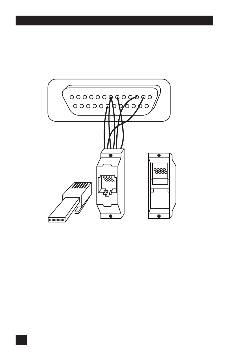
54
ETHERNET PRINT SERVER
Appendix A: RJ-45 Adapter Pinout
Fig. A-1. RJ-45 Adapter.
DB25 Female Connector
13
25
RJ12
(or MMJ)
123456
(to LE3700A)
Reverse side of
RJ12 (or MMJ)
12 34 56
RJ12 (or MMJ)
Connector
1
14
5
123
6
4
Page 56

55
APPENDIX A: RJ-45 Adapter Pinout
Table A-1. RJ-45 Adapter Pinout.
Pin # Signal Name Pin # DB25 to DB25 to
(at EPS) (at EPS)* at adapter terminal/ modem
printer
8 CTS (in) 1 4 5
7 DSR (in) 2 20 6
6 Receive 3 2 3
5 Rx Return 4 7 7
4 Tx Return 5 7 7
3 Transmit 6 3 2
2 DTR (out) 7 6 20
1 RTS (out) 8 5 4
*This table assumes that you are using a swapped cable, in which pin 1 at one end
goes to pin 8 at the other end. The diagram shows a terminal/printer (non-modem)
example. You can use the inner 6 pins (2-7) with existing RJ-12 connectors, but they
will not provide RTS/CTS flow control.
Page 57

56
ETHERNET PRINT SERVER
Appendix B: Cable Limits
B.1 Network/Cable Limits
Thinwire (10BASE2) segments can be no longer than 185 m (600 ft.), and
can have taps no closer together than 0.5 m (1.5 ft.) apart. These can be
no more than 30 taps per segment.
Thickwire segments can be no longer than 500 m (1650 ft.). Taps must
be increments of 2.5 m (8 ft.) apart. There can be no more than 100 taps
per segment.
10BASE-T segments can be no longer than 100 m (330 ft.). Longer
segments may work in some instances, but we do not recommend them.
Cable is phone grade (or better) unshielded twisted-pair (UTP) cable, RJ-45
connectors.
AUI cables can be no longer than 50 m (165 ft.).
For all media types, a total of 4 repeaters are allowed between any two
nodes connected by 5 segments of cable. A maximum of 3 segments between
any two nodes can have taps on them—the others must be point-to-point links
(10BASE-T or fiber). For example, if you use 5 segments to go across 4
repeaters between 2 nodes, 2 of the segments (5-3=2) must have NO taps.
B.2 Serial Cables
The EPS complies to the RS-423 specification. If you connect the EPS to an
RS-232 device, it is subject to the RS-232 limits shown below. If you connect
the EPS to an RS-422 device, it is subject to the RS-422 limitations.
• RS-232 lines are limited to 15 m (50 ft.) in length.
• RS-422 lines are limited to 300 m (1000 ft.).
B.3 Parallel Cables
Parallel cables (Centronics or Dataproducts) can be no longer than
6.1 m (20 ft.).
All parallel cables must be internally twisted (each signal with its return
signal) for the interfaces to function properly. If you don’t follow this rule,
the EPS may lose data.
Page 58

57
APPENDIX C: Power-Up Tests
Appendix C: Power-Up Tests
When you power up the server, it goes through the power-up diagnostics.
These diagnostics first blink the LEDs to indicate that the processor can
execute firmware correctly and that you can individually address the LEDs.
It then tests RAM, the serial channels, and the Ethernet controller. After this,
it checksums the NVR (non-volatile RAM) to verify that the saved data,
including its Ethernet address, has not been corrupted. If the checksum test
fails, the EPS sets the Ethernet address to 00-00-00-00-00-00 (which is a known
invalid address) and resets other server parameters to factory-default values,
and calculates a new checksum.
After the EPS completes power-up diagnostics, it will attempt to boot.
If the installed Ethernet address is not valid, as in the case above, the server
will enter the boot monitor.
C.1 Connections and Termination
To successfully complete power-up diagnostics, you must have a valid network
connection. If you are using the AUI port, you must connect it to a properly
terminated transceiver or an AUI cable connected to a thickwire tap.. If
you are using 10BASE-T, you must connect the port to a 10BASE-T hub or
another host. A faulty transceiver or improperly terminated Ethernet may
interfere with the server’s power-up diagnostics. At power-up time, the server
does not care if there are any devices connected to the serial or parallel ports;
however, if it detects errors, it will attempt to report the problem to a device
connected to the serial port.
C.2 LED Patterns
As power-up tests progress, the EPS will output testing status to the LEDs in
the following sequence (although they may change too quickly to observer
when the tests pass). If a pattern is continuous, then the diagnostics have
detected an error during that test. When the EPS detects an error, it writes
the error code to the LEDs and then attempts to write a failure message out
of port 1 at 9600 baud, 8 bits, no parity, to notify the user. Depending on the
nature of the error, this may not be possible. In each of the situations
described below, the four LEDs are shown in Table C-1 as being on (•) or
off (-).
Page 59

58
ETHERNET PRINT SERVER
Table C-1. LED Patterns.
LED State Meaning
• - - - (1/2 second) First test. “Hello” message. Indicates that code is running
- • - - (1/2 second) and that the LEDs themselves are functional.
- - • - (1/2 second)
- - - • (1/2 second)
•••• (Continuous) The EPS detected an error accessing the gate array.
- - - - Performing checksum tests on ROM.
- - - • Testing RAM bank 0 (0s, 1s, and addresses).
- - • -
- - • • Testing RAM bank 1 (0s, 1s, and addresses).
- • - -
- • - • Testing for shorts or opens on low order address lines.
- • • - Testing address mapping for errors on high address lines.
- • • • Starting UART internal loopback tests.
• - - -
• - - • Starting Ethernet controller internal loopback tests.
• - • -
• - • •
• • - - Starting parallel loopback test.
• • - • Checking NVR checksum.
Page 60

59
APPENDIX C: Power-Up Tests
Table C-1. LED Patterns (continued).
LED State Meaning
• • • - (3 seconds) NVR check sum error: Ethernet address and other server
parameters are set to factory defaults. You will have to
restore the Ethernet address from the back label before
you can use the server. Contact Technical Support.
• • • • (3 seconds) Power-up tests passed. NVR checksum good, ready to
boot the terminal server.
• - - - (1/2 second) Indicates that the server has detected a factory default
- • - - (1/2 second) Ethernet address (00-00-00-00-00-00), and is
- - • - (1/2 second) investigating whether factory test hardware is present. It
- - - • (1/2 second) will attempt normal boot procedures within 3 seconds.
Page 61

60
ETHERNET PRINT SERVER
Appendix D: Network Logins
Configuring the EPS from the network is rather simple. You can log into the
EPS via LAT, TCP/IP, and NetWare, and you will have a command “shell”
with which to configure the EPS. The EPS provides utilities to allow you to
configure it from AppleTalk and NetWare nodes without logging in.
If you do log in to the EPS, it will give you a “#” prompt. You must enter the
EPS’s login password and press <Return>. The default password is “ACCESS,”
and you can change it via the SET/DEFINE SERVER LOGIN PASSWORD
command. The EPS will then ask you for a username. Choose any name and
press <Return>. From the “Local>” prompt, type HELP to get a list of EPS
commands and get in-depth help on each command.
For NetWare, the EPS provides a utility called EPSCON on a floppy disk.
Copy it onto your workstation to use it. With EPSCON, you can either log
into an EPS or just send individual commands to it. There are 3 formats:
C:> EPSCON [?]
If you do not specify a host, the utility lists all available print servers. Using ?
will show the various EPSCON syntax options.
C:> EPSCON eps1_name
This command opens a login session to the EPS. The file server learns of any
EPSs via network broadcasts—it does not need any configuration to be able to
connect to it. At login, the utility displays the “#” password prompt. Type
“ACCESS” and press <Enter>. Then, enter a username and press <Enter>.
You will then be at the EPS local prompt, and can type HELP for a command
list.
C:> EPSCON host [SHOW | RESET | SERVERNAME]
This command prompts for the EPS login password (“ACCESS” by default)
and then sends a single command to the EPS without logging in. SHOW will
show NetWare activity on the EPS, RESET will force the EPS to re-scan the
file servers on the network, and SERVERNAME will attempt to change the
EPS’s server name. If it changes the server name, the names of any default
(EPS_xxxxxx_xx) service will also change to use the new server name and the
_xx suffix. For TCP/IP, you can use Telnet or Rlogin to connect to the EPS.
If the EPS’s IP address is 192.77.23.42, doing a
% telnet 192.77.23.42
will place you at the password (“#”) prompt.
Page 62

61
APPENDIX D: Network Logins
From LAT devices, the server’s name (EPS_xxxxxx) should appear as a
service on LAT-enabled hosts. If you connect to that service, you will be
connected at the password prompt. For example:
VMS> SET HOS/LAT EPS_45E23A
to connect from a VMS LAT host, or
Local> CONNECT EPS_45E32A
to connect from LAT devices such as other servers.
To configure the EPS under control of a Macintosh workstation, the utility
provides an optional application. When you run it, it will open a window and
wait for you to specify the EPS name and password. You can then configure
various EPS settings until you exit the application or select a different EPS.
Page 63

62
ETHERNET PRINT SERVER
Appendix E: Quick-Start Guide
NOTE: Read this appendix only if you are loading a new boot image on the print server.
If you’re a manager who has installed print/terminal servers before and are
very familiar with BOOTP, RARP, TFTP, NetWare, and/or MOP downloading
configuration, read this chapter to set your EPS up quickly.
If you’ve never installed a server before, read the full installation
instructions in Chapter 3.
Experienced managers can follow these steps to quickly setup the EPS:
1. Attach the server to the network, via transceiver, AUI cable, or 10BASE-T
cable.
2. Attach the console device (we recommend a terminal) to the server. The
server will expect a console device connected to port 1, at 9600 baud, 8-bit
characters, and no parity.
3. If you have not yet installed the server software, do so now. Installing the
software will require approximately 5 megabytes of disk space.
• VMS: Use vminstal to install in the contents of the distribution tape. The
.SYS files will be installed in SYS$SYSROOT:[MOM$SYSTEM] by default.
Ensure that this directory is in the MOM$LOAD search path and that
MOP downloading is enabled.
• NetWare: Copy the download file(s) (PS1.SYS) from the enclosed floppy
disks onto your file server. The files will gave to be in the login directory
for this file server (generally SYS:\LOGIN). Also, there is an 11-character
limit on the EPS pathname—make sure the login directory conforms to
this limit.
• UNIX: tar the tape into the /tmp directory. You will then have to place
the download file (ETS.SYS, SPS.SYS, and/or PS1.SYS) file in whichever
directory your host’s TFTP server will look for them. If TFTP requires no
default directory, the EPS itself will allow only 15 characters of path
information, so place the files in a directory adhering to this limit. The
directory and files must have world read privileges.
If your host supports BOOTP, you may wish to add the server to the host’s
BOOTP configuration file (usually /usr/etc/bootptab). You will have to
add the server’s hardware address (from the rear of the unit), its IP
address, and the filename to download (PS1.SYS for the EPS). For
example:
Page 64

63
APPENDIX E: Quick-Start Guide
#Note that #s are typically comment characters.
#host htyp hardware address IP address bootfile
eps1 1 00:80:a3:04:19:4c 192.1.240 /tftpboot/PS1.SYS
Recall that in BOOTP and TFTP, the path and filename are case-sensitive.
If your host supports RARP instead of BOOTP, you can configure the host
to reply to the EPS’s RARP requests and give the EPS its IP address. In
general, the EPS needs to be in the host’s /etc/hosts and /etc/ethers files
for the host to reply. Since RARP provides no filename information,
TFTP will request the default filename with no path. If you need a
specific path for the download file, you will have to use BOOTP or
manual configuration. The EPS will use the RARP reply host as the
loadhost.
4. Configure the EPS: Power on the unit. The EPS will always attempt a
BOOTP configuration; if the BOOTP is not answered, it will send a
broadcast RARP request as well. It will then attempt a TFTP download if
it has an IP address and a loadhost. If the TFTP fails or the EPS does not
attempt it, the EPS will attempt NetWare if you’ve specified a file server.
If you did not set a file server, or if the download fails, the EPS will try
MOP. If you use BOOTP, RARP, or MOP, the server should discover its
load host automatically and download the file successfully.
If garbage characters appear on the console, check the terminal settings
and serial line configuration.
If you are using NetWare to download, or if the EPS cannot discover its
filename or IP address via TFTP, you will have to configure it manually.
If the server is not displaying the “Boot>” prompt, press Return or Break
when it is waiting between download attempts. You should get the
“Boot>” prompt and be able to type on the console device. What you
configure depends on the download method:
• TFTP: You will need to configure the server’s and loadhost’s IP addresses,
and the path and filename of the download file:
Boot> SET SERVER IPADDRESS w.x.y.z
Boot> SET SERVER LOADHOST a.b.c.d
Boot> SET SERVER SOFTWARE /directory/ps1.sys
Boot> FLASH
Page 65

64
ETHERNET PRINT SERVER
• NetWare: You need to specify the file server to load from and the path
and filename of the download file. The download file must be in the
login directory of the file server you are loading from (because of login
restrictions).
Boot> SET SERVER NETWSERVER fileserver
Boot> SET SERVER SOFTWARE SYS:\LOGIN\PS1.SYS
Boot> FLASH
NOTE: The path and filename are case-sensitive for TFTP, and are not case-sensitive for
NetWare.
Page 66

65
NOTES
Page 67

1000 Park Drive • Lawrence, PA 15055-1018 • 724-746-5500 • Fax 724-746-0746
© Copyright 2002. Black Box Corporation. All rights reserved.
 Loading...