

Page 1
NOVEMBER 1992
LE3010A
LE3011A
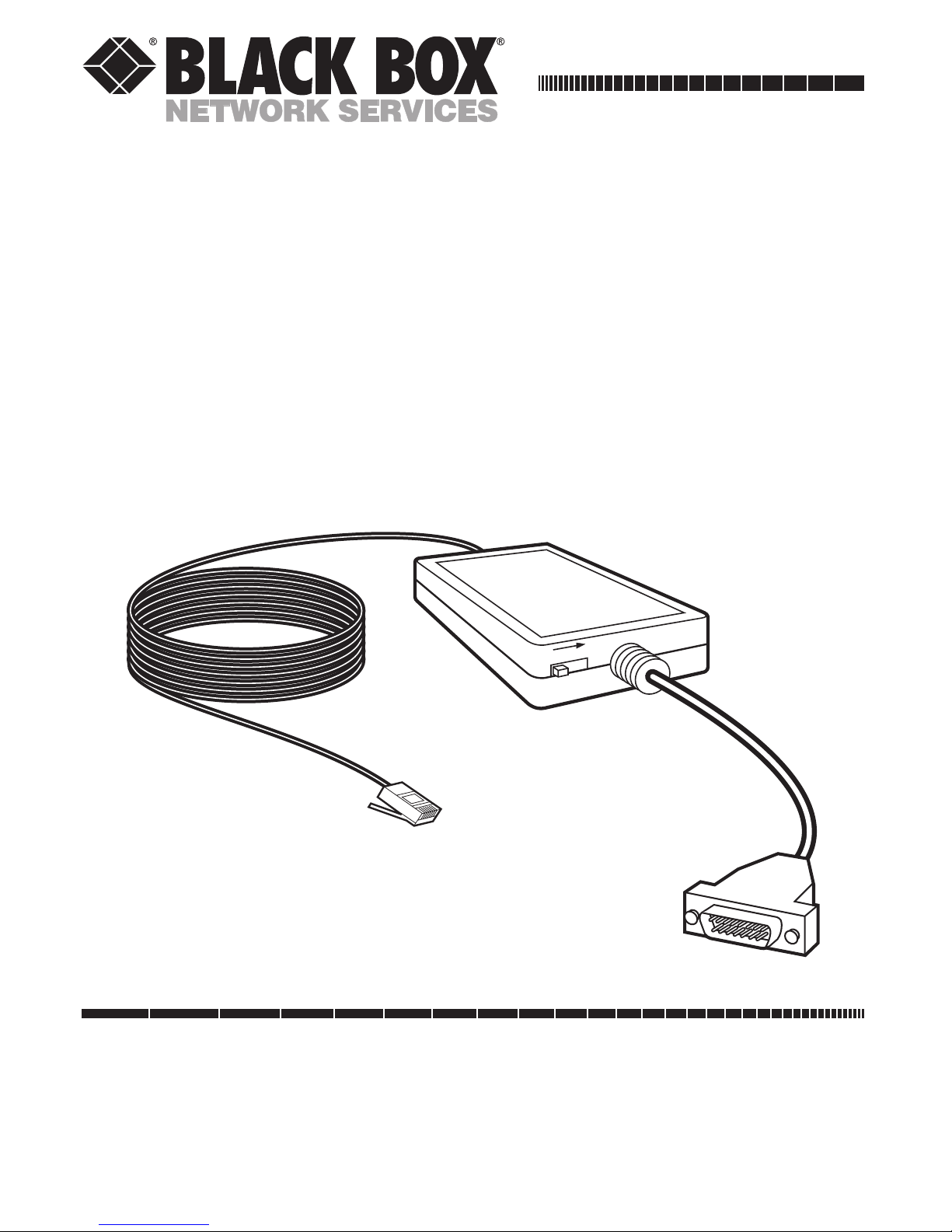
Mini 10BASE-T Transceiver
w/Cable (Slidelock or
Screwlock)
CUSTOMER SUPPORT INFORMATION
Order toll-free in the U.S. 24 hours, 7 A.M. Monday to midnight Friday: 877-877-BBOX
FREE technical support, 24 hours a day, 7 days a week: Call 724-746-5500 or fax 724-746-0746
Mail order: Black Box Corporation, 1000 Park Drive, Lawrence, PA 15055-1018
Web site: www.blackbox.com • E-mail: info@blackbox.com
10 BASE-T
TRANSCEIVER
SQE ON
POWER/TX
LINK/RCV
COLLISION
•
•
•
JABBER
•
Page 2
2
MINI 10BASE-T TRANSCEIVER W/CABLE
FEDERAL COMMUNICATIONS COMMISSION
RADIO FREQUENCY INTERFERENCE
STATEMENT
This equipment generates, uses, and can radiate
radio frequency energy and if not installed and
used properly, that is, in strict accordance with the
manufacturer’s instructions, may cause interference
to radio communication. It has been tested and
found to comply with the limits for a Class A
computing device in accordance with the
specifications in Subpart J of Part 15 of FCC rules,
which are designed to provide reasonable
protection against such interference when the
equipment is operated in a commercial
environment. Operation of this equipment in a
residential area is likely to cause interference, in
which case the user at his own expense will be
required to take whatever measures may be
necessary to correct the interference.
Changes or modifications not expressly approved
by the party responsible for compliance could void
the user’s authority to operate the equipment.
Page 3

3
MINI 10BASE-T TRANSCEIVER W/CABLE
This digital apparatus does not exceed the Class A limits
for Radio noise emission from digital apparatus set out in
the Radio Interference Regulation of the Canadian
Department of Communications.
Le présent appareil numérique n’émet pas de bruits
radioélectriques dépassant les limites applicables aux
appareils numériques de la classe A prescrites dans le
Règlement sur le brouillage radioélectrique édicté par le
ministère des Communications du Canada.
Page 4

4
MINI 10BASE-T TRANSCEIVER W/CABLE
1.0 Specifications
Standards
— IEEE 802.3 10BASE-T
Indicators
— (4) LEDs: Power/TX, LINK/RCV,
Collision, Jabber
Connectors
— (1) AUI 15-pin male, (1) RJ-45
female
Temperature
— 32 to 131° F (0 to 55° C)
Humidity
— 10-90% (non-condensing)
Power
— From workstation AUI connection
Size
— Transceiver: 0.75"H x 2"W x 2.75"D (1.9 x
5.1 x 7 cm);
Attached RJ-45 cable: 15 ft. (4.5 m) long
Attached AUI cable: 6 ft (1.8 m) long
Page 5

5
CHAPTER 2: Introduction
Weight
— 0.375 lb. (0.17 kg)
2.0 Introduction
The Mini 10BASE-T Transceiver w/Cable connects
a host to a 10BASE-T network using your existing
standard Ethernet adapter card. Two models are
available:
• LE3010A, Mini 10BT Transceiver w/Cable
(Slidelock)
• LE3011A, Mini 10BT Transceiver w/Cable
(Screwlock)
Both models include the following:
• Transceiver
• Attached 6-ft. molded office transceiver cable
• Attached 15-ft. 24 AWG stranded UTP wire
Page 6

6
MINI 10BASE-T TRANSCEIVER W/CABLE
3.0 Configuration
3.1 Set SQE Switch
SQE is the Signal Quality Error function that
provides “heartbeat” for network data collision
detection setting. If the host to which the
transceiver is connected is a computer, set the SQE
switch to ON. If the host is a repeater (coaxial
cable use), set the SQE switch to OFF. Fig. 3-1
shows the location of the SQE switch.
Fig. 3-1. SQE Switch.
POWER/TX
10BASE-T
TR ANSCEIVER
POWER/TX
LINK/RVC
JABBER
COLLISION
N
O
E
Q
S
LINK/RVC
COLLISION
JABBER
SQE ON
Page 7

7
CHAPTER 3: Configuration
Fig. 3-2. RJ-45 Pinout Assignment.
3.2 RJ-45 Pinout Assignment
Fig. 3-2 shows the pinouts of the RJ-45 connector.
8
7
6
5
4
3
2
1
RX -
RX +
TX -
TX +
Page 8

8
MINI 10BASE-T TRANSCEIVER W/CABLE
Fig. 4-1. Connecting the Transceiver to the Host and Hub.
4.0 Installation
4.1 Connect the Transceiver to the Host and to the Hub
1. Plug the DB15 connector of the AUI cable
into the host’s DB15 port.
2. Plug the RJ-45 connector of the UTP cable
into the 10BASE-T hub. See Fig. 4-1.
10BASE-T
TR ANSCEIVER
POWER/TX
LINK/RVC
JABBER
COLLISION
N
O
E
Q
S
Page 9

9
CHAPTER 5: LED Indicators
5.0 LED Indicators
The LED indicators on the transceiver show the
following:
•
POWER/TX
—The indicator should be
constantly ON, once you connect the
transceiver to the host and the hub. When
this indicator blinks, data is being transmitted.
•
LINK/RCV
—When this indicator is
continuosly ON, data link is OK and the
transceiver is ready to receive data. When this
indicator blinks, data is being transmitted.
•
COLLISION
—This indicator should be OFF
most of the time. When it is ON, data
collision is occurring. Data collision is not an
abnormal situation. It may sometimes happen
when the host to which the transceiver is
connected attempts to transmit data on the
network while another host is also attempting
to do the same. When this happens, data
collides on the network. Both hosts will then
back off and attempt to retransmit at random
intervals. The transceiver retries until data
collisions cease.
Page 10

10
MINI 10BASE-T TRANSCEIVER W/CABLE
•
JABBER
—This indicator should be OFF
most of the time. When it is ON, the data
transmission function is being interrupted
because of an abnormally long output data
stream. The function is interrupted to
prevent the corrupted data from being sent
over the network.
Page 11

11
NOTES
Page 12

1000 Park Drive • Lawrence, PA 15055-1018 • 724-746-5500 • Fax 724-746-0746
© Copyright 1992. Black Box Corporation. All rights reserved.
 Loading...