

Page 1
CUSTOMER
SUPPORT
INFORMATION
Order toll-free in the U.S. 24 hours, 7 A.M. Monday to midnight Friday: 877-877-BBOX
FREE technical support, 24 hours a day, 7 days a week: Call 724-746-5500 or fax 724-746-0746
Mail order: Black Box Corporation, 1000 Park Drive, Lawrence, PA 15055-1018
Web site: www.blackbox.com • E-mail: info@blackbox.com
Stackable MiniHub
Stackable MiniHub
Ports
1
2
3
4
5
6
7
8
Stack Enable
LINK/TX
8
7
6
5
4
3
2
1
PORTS
PWR
COL
POL/TX
UP LINK
Off
IRB1
IRB2
On
PWR
12VDC, 1A
JUNE 2001
LE2801A
LE2801AE
LE2801A-BNC
LE2801AE-BNC
LE2801A-FO
LE2801AE-FO
Page 2

FEDERAL COMMUNICATIONS COMMISSION
AND INDUSTRY CANADA
RADIO FREQUENCY INTERFERENCE STATEMENT
Class B Digital Device. This equipment has been tested and found to comply with the
limits for a Class B computing device pursuant to Part 15 of the FCC Rules. These
limits are designed to provide reasonable protection against harmful interference
in a residential installation. However, there is no guarantee that interference will not
occur in a particular installation. This equipment generates, uses, and can radiate
radio frequency energy, and, if not installed and used in accordance with the
instructions, may cause harmful interference to radio communications. If this
equipment does cause harmful interference to radio or telephone reception, which
can be determined by turning the equipment off and on, the user is encouraged to
try to correct the interference by one of the following measures:
• Reorient or relocate the receiving antenna.
• Increase the separation between the equipment and receiver.
• Connect the equipment into an outlet on a circuit different from that
to which the receiver is connected.
• Consult an experienced radio/TV technician for help.
Caution:
Changes or modifications not expressly approved by the party
responsible for compliance could void the user’s authority to operate the
equipment.
To meet FCC requirements, shielded cables and power cords are required to
connect this device to a personal computer or other Class B certified device.
This digital apparatus does not exceed the Class B limits for radio noise emission from
digital apparatus set out in the Radio Interference Regulation of Industry Canada.
Le présent appareil numérique n’émet pas de bruits radioélectriques dépassant les limites
applicables aux appareils numériques de classe B prescrites dans le Règlement sur le brouillage
radioélectrique publié par Industrie Canada.
FCC AND IC STATEMENTS
Page 3

STACKABLE MINIHUB
NORMAS OFICIALES MEXICANAS (NOM) ELECTRICAL SAFETY STATEMENT
INSTRUCCIONES DE SEGURIDAD
1. Todas las instrucciones de seguridad y operación deberán ser leídas antes
de que el aparato eléctrico sea operado.
2. Las instrucciones de seguridad y operación deberán ser guardadas para
referencia futura.
3. Todas las advertencias en el aparato eléctrico y en sus instrucciones de
operación deben ser respetadas.
4. Todas las instrucciones de operación y uso deben ser seguidas.
5. El aparato eléctrico no deberá ser usado cerca del agua—por ejemplo,
cerca de la tina de baño, lavabo, sótano mojado o cerca de una alberca,
etc..
6. El aparato eléctrico debe ser usado únicamente con carritos o pedestales
que sean recomendados por el fabricante.
7. El parato eléctrico debe ser montado a la pared o al techo sólo como sea
recomendado por el fabricante.
8. Servicio—El usuario no debe intentar dar servicio al equipo eléctrico más
allá a lo descrito en las instrucciones de operación. Todo otro servicio
deberá ser referido a personal de servicio calificado.
9. El aparato eléctrico debe ser situado de tal manera que su posición no
interfiera su uso. La colocación del aparato eléctrico sobre una cama,
sofá, alfombra o superficie similar puede bloquea la ventilación, no se
debe colocar en libreros o gabinetes que impidan el flujo de aire por los
orificios de ventilación.
10. El equipo eléctrico deber ser situado fuera del alcance de fuentes de
calor como radiadores, registros de calor, estufas u otros aparatos
(incluyendo amplificadores) que producen calor.
Page 4

NOM STATEMENT, TRADEMARKS
11. El aparato eléctrico deberá ser connectado a una fuente de poder sólo
del tipo descrito en el instructivo de operación, o como se indique en
el aparato.
12. Precaución debe ser tomada de tal manera que la tierra fisica y la
polarización del equipo no sea eliminada.
13. Los cables de la fuente de poder deben ser guiados de tal manera que
no sean pisados ni pellizcados por objetos colocados sobre o contra
ellos, poniendo particular atención a los contactos y receptáculos donde
salen del aparato.
14. El equio eléctrico debe ser limpiado únicamente de acuerdo a las
recomendaciones del fabricante.
15. En caso de existir, una antena externa deberá ser localizada lejos de las
lineas de energia.
16. El cable de corriente deberá ser desconectado del cuando el equipo no
sea usado por un largo periodo de tiempo.
17. Cuidado debe ser tomado de tal manera que objectos liquidos no sean
derramados sobre la cubierta u orificios de ventilación.
18. Servicio por personal calificado deberá ser provisto cuando:
A: El cable de poder o el contacto ha sido dañado; u
B: Objectos han caído o líquido ha sido derramado dentro del
aparato; o
C: El aparato ha sido expuesto a la lluvia; o
D: El aparato parece no operar normalmente o muestra un cambio
en su desempeño; o
E: El aparato ha sido tirado o su cubierta ha sido dañada.
TRADEMARKS USED IN THIS MANUAL
Velcro®is a registered trademark of Velcro USA.
Any other trademarks mentioned in this manual are acknowledged to be the property
of the trademark owners.
Page 5

STACKABLE MINIHUB
Contents
Chapter Page
1. Specifications ............................................................................................... 1
2. Introduction ................................................................................................. 3
2.1 General Overview .................................................................................. 3
2.2 Features and Benefits ........................................................................... 5
2.3 Applications ........................................................................................... 7
3. Installation .................................................................................................... 9
3.1 Before You Install: The Complete Package ......................................... 9
3.2 The Installation Procedure .................................................................. 9
3.3 Stacking the MiniHubs .........................................................................12
3.4 Cascading ............................................................................................ 16
3.5 BNC Connection (LE2801A-BNC, LE2801AE-BNC only) .................17
3.6 Fiberoptic Connection (LE2801A-FO, LE2801AE-FO only)..............17
4. Operation ................................................................................................... 19
4.1 LED Indicators .................................................................................... 19
4.2 Operating Features ............................................................................. 19
5. Troubleshooting ........................................................................................ 20
5.1 Things to Check .................................................................................. 20
5.2 Calling Black Box ................................................................................ 21
5.3 Shipping and Packaging ..................................................................... 21
Page 6

1
CHAPTER 1: Specifications
Compliance — FCC Part 15 Class A and B, IC Class/classe B,
VDE Class B
Standard — IEEE 802.3 Ethernet v. 1.0/2.0
Interface — LE2801A, LE2801AE: 10BASE-T; LE2801A-BNC,
LE2801AE-BNC: 10BASE2; LE2801A-FO,
LE2801AE-FO: 10BASE-FL
Data Rate — 10 Mbps
Partitioning — Automatic after 32 consecutive collisions
Reconnection — Occurs after 512 bits of error-free transmission
Maximum
Segment Length — UTP (unshielded 10BASE-T): 100 m (328 ft.);
STP (shielded 10BASE-T): 150 m (492 ft.);
AUI drop cable: 50 m (164 ft,);
10BASE2 ThinNet (BNC): 185 m (607 ft.);
10BASE5: 500 m (1,640 ft.);
10BASE-FL multi-mode fiberoptic: 2 km (6562 ft.)
User Controls — Rear-mounted slide switch for straight-through vs.
crossover (uplink) operation on port 8
Stackable switch to specify which hub is at the base
of the stack
Indicators — (19) Front-mounted recessed LEDs:
(1) Power; (9) Link/TX (1 for each port);
(9) Pol/RX
(1 for each port)
1. Specifications
Page 7

2
STACKABLE MINIHUB
Connectors — LE2801A, LE2801AE: (8) front-mounted shielded-
type RJ-45 female; (1) rear-mounted DB15 female
AUI port; LE2801A-BNC, LE2801AE-BNC: same
as LE2801A, plus (1) rear-mounted BNC with
internal termination switch; LE2801A-FO,
LE2801AE-FO: same as LE2801A, plus one rear
fiber ST connector
Leads/Signals
Supported — Pins 1, 2, 3, and 6
Enclosure — High-strength steel
Cooling Method — Convection
Operating
Temperature — 32 to 122˚ F (0 to 50˚ C)
Storage
Temperature — –4 to 140˚ F (–20 to 60˚ C)
Humidity — 10 to 95% noncondensing
Power — From wallmount power supply:
LE2801A, LE2801A-BNC, LE2801A-FO:
Input: 120 VAC, 60 Hz;
LE2801AE, LE2801AE-BNC, LE2801AE-FO:
Input: 230 VAC, 50 Hz;
All models: Output: 12 VDC, 1 amp;
All models: Consumption: 10 watts maximum
Size — 0.8"H x 5"W x 4.4"D (1.9 x 12.7 x 11.2 cm)
Weight — Net: 1.3 lb. (0.6 kg);
Net plus power supply: 2.3 lb. (1.05 kg)
Page 8

3
CHAPTER 2: Introduction
2.1 General Overview
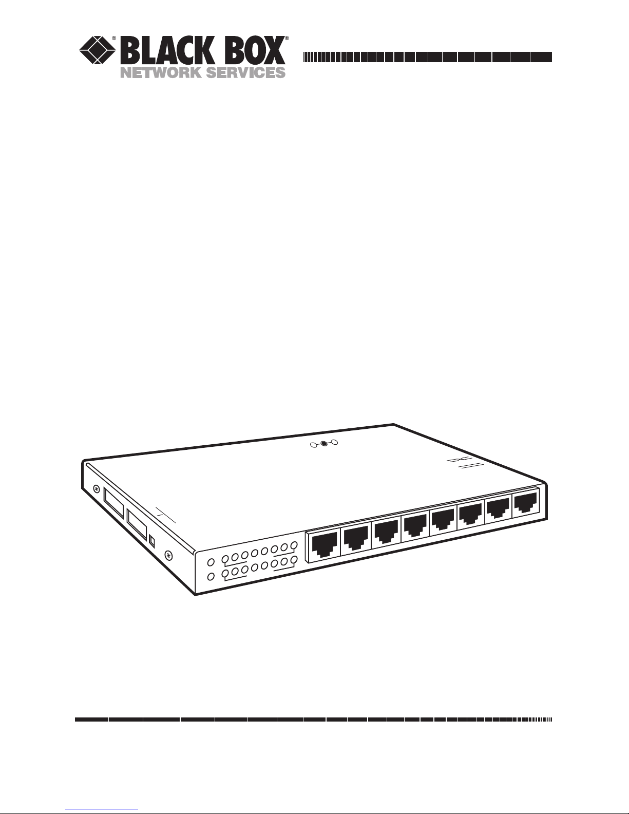
The Stackable MiniHub is a workplace hub in a very compact package.
It is simple to install and use in an office or lab environment, requiring no
special rack cabinets or wiring-closet apparatus. It is a standard physical-layer
Ethernet product and operates independently of all software.
Stackable MiniHubs provide a simple and inexpensive solution for
networking a personal multi-system office using 10BASE-T twisted-pair
cabling. They can expand from an eight-port hub up to 40 ports.
Six models are available:
• LE2801A, LE2801AE: Basic model, has eight shielded twisted-pair ports
in the front and an AUI port in the rear. LE2801A has a 120-VAC power
supply, LE2801AE has a 230-VAC power supply.
• LE2801A-BNC, LE2801AE-BNC: Same as LE2801A, but has one
additional BNC port in the rear.
• LE2801A-FO, LE2801AE-FO: Same as LE2801A, but has one additional
fiber-ST port in the rear.
Stackable MiniHubs are also well suited for small-to-medium-size office or
lab environments (two to 40 users) that need an independent Ethernet
network. They operate as self-sufficient units to provide 10BASE-T Ethernet
connectivity for local users and devices. Small independent networks built
using the Stackable MiniHubs are easily expanded by taking advantage of the
MiniHubs’ stacking ability.
The small size of the Stackable MiniHubs make them very useful for
demonstration situations in conference rooms and in exhibitions where a
temporary or expansion network is needed. The MiniHubs are also handy as a
piece of test equipment that can be easily inserted into the network to provide
a test port, and then removed after the testing is done. They take up minimal
space and use minimal power, and are rugged enough to be carried in a coat
pocket for emergencies.
Stackable MiniHubs fit easily into the workplace environment. They can
be table-top- or shelf-mounted, or you can use the included Velcro®strip to
mount MiniHubs on walls or on the back or side of a desk or cabinet. All of
the wiring connectors are in the same plane so that wiring space is neat and
minimal. The external power supply conveniently plugs into any available AC
wall receptacle or power strip.
2. Introduction
Page 9
4
STACKABLE MINIHUB
The Stackable MiniHub’s RJ-45 ports support connection of up to eight
workstations or other network devices over full-length 10BASE-T cable
segments. Stackable MiniHubs fully comply with the IEEE 802.3 specification
for repeater functionality: They perform signal amplification, retiming of data
packets, and regeneration of preamble bits for each packet received. They will
also detect collisions, extend collision fragments, and automatically partition
and reconnect individual ports in order to keep problems on one segment
from causing downtime elsewhere on the network.
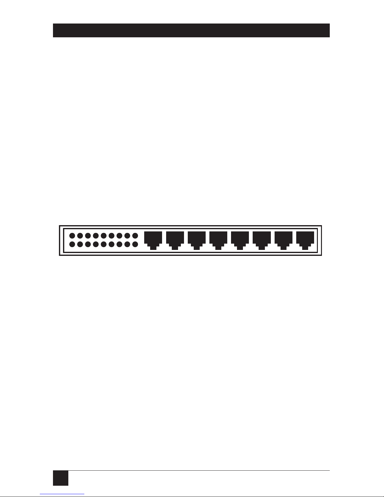
Stackable MiniHubs have LINK and RX LEDs for each front-panel RJ-45
port, located above the corresponding ports (see the illustration below); one
LED to the left of the LINK LED for (and located above) the rear-panel AUI
port, and one LED for AC power, located at the rear above the external
power-supply connection. This makes observing the operation and status
of the ports easy.
Figure 2-1. Front Panel of the Stackable MiniHub.
The included external wallmount power supply uses AC input power of
120 VAC/60 Hz (A models) or 230 VAC/50 Hz (AE models). Its lightweight
cord carries DC power to the barrel-type power jack on the rear panel (shown
in Figure 2-2) of the MiniHub.
Page 10

5
CHAPTER 2: Introduction
Figure 2-2. Rear Panel of the Stackable MiniHub.
2.2 Features and Benefits
• Interconnectability with Existing Ethernet Networks
Your Stackable MiniHub has a manual Up-Link switch that you can use to
cross the pinning of its 8th port. In this setting, you can connect 10BASET cable from an existing Ethernet environment (such as the central hub
for the building) to the MiniHub’s 8th port.
• Interoperability with Other Ethernet Devices
Stackable MiniHubs are completely interoperable with other Ethernetcompliant network devices. Each is fully compliant with IEEE 802.3
specifications for 10-Mbps CSMA/CD operation. This allows Stackable
MiniHubs to be integrated into any standard Ethernet network.
• Installation Versatility
You can easily install Stackable MiniHubs in almost any office or lab
location. The tiny package is very unobtrusive and is typically mounted
with Velcro.
• Robust Network Operation
Stackable MiniHubs use the “star” network topology and have automatic
per-port partitioning and reconnection. A fault on one segment is isolated
from the rest of the network, avoiding most network downtime.
Page 11

• Simple Network Diagnosis and Maintenance with LEDs
Stackable MiniHubs are equipped with a full complement of LEDs to
show the status of basic network activity. LINK LEDs for each port offer
a very simple way to verify operational connections for each 10BASE-T
segment.
• Low-Cost Standalone 10BASE-T Connectivity
Operating your Stackable MiniHub in a standalone environment as a selfsufficient device is a very low-cost method of providing small workgroups
access to a variety of Ethernet networking services such as file sharing,
email, printer sharing, and other computer information.
• High-Quality Construction
Stackable MiniHubs have rugged steel enclosures and are compliant with
rigid Class B emission standards, making them suitable for commercial
and home offices.
6
STACKABLE MINIHUB
Page 12

7
CHAPTER 2: Introduction
Figure 2-3. Connecting to an Existing Network.
2.3 Applications
Expanding from one to multiple ports at an existing site is easy, and
requires no modification to typical building wiring. Simply plug the
existing networked device’s network-cable segment into one of the Stackable
MiniHub’s front-mounted RJ-45ports. With the MiniHub’s rear-mounted UpLink switch set to “=x=”, run 10BASE-T cable from the existing network outlet
to the MiniHub’s 8th port. Then plug the DC power cord of the MiniHub’s
external power supply into the MiniHub’s power jack, plug in the power
supply’s transformer, and there you are: In minutes, you have added eight
new ports for other networked devices (see the illustration below).
Page 13

8
STACKABLE MINIHUB
Stackable MiniHubs may also be used standalone to network a local multi-user
system, as shown below. Up to 8 RJ-45 user ports are available where only
10BASE-T wiring is used, and full-length Ethernet segments are supported
on all segments. In this application, set the Up-Link switch to the straightthrough or “===” position, so that the MiniHub’s 8th port is a user port, not
an up-link to another hub.
Figure 2-4. Using the Stackable MiniHub as a Standalone Hub.
Page 14

9
CHAPTER 3: Installation
3.1 Before You Install: Inspecting the Complete Package
Examine the shipping container for obvious damage before installing the
MiniHub; notify the carrier of any damage which you believe occurred during
shipment ar delivery. Inspect the contents of this package for any signs of
damage and make sure that you received these items:
• (1) Stackable MiniHub
• (1) External 120-VAC 60-Hz power supply
• (1) Velcro tape section, approximately 3 inches (7.6 cm) in length
• (2) Brackets for optional screw-mounting
• (1) 2-inch (5.1-cm) ribbon cable (stacking cable)
• (1) Copy of this manual
Remove the Stackable MiniHub from the shipping container. Keep the
container in case you need to ship the unit later.
If any items are missing or damaged, contact Black Box. If you need to
return the unit, see Sections 5.2 and 5.3.
3.2 The Installation Procedure
Installing a Stackable MiniHub is very simple. First, keeping in mind that it
must be within 6 feet (1.8 m) of an AC outlet, decide how and where you’re
going to mount the MiniHub.
3.2.1 M
OUNTING THEMINIHUB
Tabletop- or Shelf-Mounting
Stackable MiniHubs are easily mounted on a tabletop or shelf, and have four
rubber feet to provide stability without scratching finished surfaces. A piece of
Velcro may be used to add additional stability if desired. When properly
installed, the top-mounted LED status indicators will be in plain view and easy
to read.
The rugged steel case of the Stackable Hub will protect it from accidental
damage in an office or lab. Keep an open area around the unit so that
convection cooling can occur while the unit is operating.
3. Installation
Page 15

10
STACKABLE MINIHUB
Wall (or Vertical-Surface) Mounting
The Stackable MiniHub comes with a piece of Velcro mounting tape. You can
use this to mount a Stackable Hub in a vertical position. Stick one side of the
Velcro to the bottom of the hub between the rubber feet. Stick the other side
of the Velcro to the desired vertical mounting location. This permits the
compact Stackable Hub to be mounted on a wall surface, on the side of a
server cabinet, on the back of a desk, or in similar convenient locations in
the workplace where the associated cables are out of the way.
As an alternative to Velcro for vertical-surface mounting, you can use the
included small brackets to mount the MiniHub with screws, as shown below.
You can use the metal screws in each side of the Stackable MiniHub’s case to
attach the brackets. With the brackets, you can mount the MiniHub in almost
any desired position.
3.2.2 P
OWERINGUP THEHUB
Once you’ve mounted the Stackable MiniHub, plug the included external
power supply’s DC power cord into the matching power jack on the Stackable
MiniHub’s rear panel. Plug the power supply’s transformer into an AC
receptacle that is six feet (2 meters) or less away. The green “PWR” LED
should light up. Now you are ready to begin attaching Ethernet cable
segments.
3.2.3 C
ONNECTINGTWISTED-PAIRSEGMENTS TO THEFRONT-PANELPORTS
1. Insert the male plug on one end of a standard 10BASE-T cable into one
of the RJ-45 female ports on the front panel of the Stackable MiniHub.
(Even though the MiniHub’s connectors are shielded, they will accept,
and operate properly with, either unshielded or shielded RJ-45 twistedpair wiring plugs.)
2. Connect the other end of each network segment to a workstation or user
device. If the MiniHub is getting AC power, it will light the “LINK” LED
corresponding to each MiniHub port that has a powered-up and
functional device attached to it.
Page 16

11
CHAPTER 3: Installation
3.2.4 U
SING THE8THPORT AND THEUP-LINKSWITCH
For the 8th RJ-45 port only, use the Up-Link crossover switch (also on the rear
panel) to select either a normal 10BASE-T connection to a user device (switch
in the “===” position) or a special network-uplink connection to another hub
or concentrator (switch in the “=x=” position). A special cross-pinned cable
for uplinks is not needed with Stackable MiniHubs, because with the Up-Link
switch in the “=x=” position the pinning is crossed inside the MiniHub.
Insert the male plug on one end of a standard 10BASE-T cable into the 8th
RJ-45 female port on the Stackable MiniHub. Connect the other end of the
network segment to a workstation or user device if the Up-Link switch is in
the “===” position, or to a network hub or concentrator if the Up-Link switch
is in the “=x=” position.
Even when the rear port is physically uplinked (cable runs from the port
to a larger network), you can logically isolate the users and devices on the
Stackable MiniHub by moving the Up-Link switch to the “===” position. In
this situation, the uplink segment is inoperative and full bandwidth is
available locally.
Page 17

12
STACKABLE MINIHUB
3.3 Stacking the MiniHubs
When you need increased network capacity, you can easily stack up to five
Stackable MiniHubs to form a single logical repeater of up to 40 RJ-45 ports.
Figure 3-1. Stacking the MiniHubs.
NOTE
Secure the units with the stacking/mounting brackets before making the
following electrical connections. You cannot install the brackets while
the connector cables are in place.
Stackable MiniHub
Ports
1
2
3
4
5
6
7
8
Stack Enable
LINK/TX
8
7
6
5
4
3
2
1
PORTS
PWR
COL
POL/TX
UP LINK
Off
IRB1
IRB2
On
PWR
12VDC, 1A
Stackable MiniHub
Ports
1
2
3
4
5
6
7
8
Stack Enable
LINK/TX
8
7
6
5
4
3
2
1
PORTS
PWR
COL
POL/TX
UP LINK
Off
IRB1
IRB2
On
PWR
12VDC, 1A
Stackable MiniHub
Ports
1
2
3
4
5
6
7
8
Stack Enable
LINK/TX
8
7
6
5
4
3
2
1
PORTS
PWR
COL
POL/TX
UP LINK
Off
IRB1
IRB2
On
PWR
12VDC, 1A
Stackable MiniHub
Ports
1
2
3
4
5
6
7
8
Stack Enable
LINK/TX
8
7
6
5
4
3
2
1
PORTS
PWR
COL
POL/TX
UP LINK
Off
IRB1
IRB2
On
PWR
12VDC, 1A
Stackable MiniHub
Ports
1
2
3
4
5
6
7
8
Stack Enable
LINK/TX
8
7
6
5
4
3
2
1
PORTS
PWR
COL
POL/TX
UP LINK
Off
IRB1
IRB2
On
PWR
12VDC, 1A
Page 18

13
CHAPTER 3: Installation
Follow these steps when stacking:
1. Switch the Stack Enable switch of the bottom Stackable MiniHub to the
“OFF” position (left).
2. Switch all other units to the “ON” position (right).
3. Using the IRB ribbon cable, connect one end to either Inter-RepeaterBus connector (IRB1 or IRB2) of the bottom Stackable MiniHub.
Connect the other end of the cable to the corresponding IRB connector
of the top Stackable MiniHub (i.e, the IRB cable connects from IRB1 to
IRB1, or from IRB2 to IRB2).
4. If you will add more Stackable MiniHubs, connect another IRB cable
from the unused IRB connector of the existing stack’s top unit to the
corresponding IRB connector of the Stackable MiniHub you will add.
Make sure that the Stack Enable Switch of the added unit is set to the
“ON” position. You can stack up to five Stackable MiniHubs in this way.
5. Each unit of the stack must be powered by its own external power supply.
Make sure that the PWR LED of each unit is lit to verify “Power On.” If
one unit of the stack is powered off, the rest of the stack will still function
properly.
Page 19

14
STACKABLE MINIHUB
Figure 3-2. Two Stacked MiniHubs—16 RJ-45 Ports.
Stackable MiniHub
Ports
1
2
3
4
5
6
7
8
Stack Enable
LINK/TX
8
7
6
5
4
3
2
1
PORTS
PWR
COL
POL/TX
UP LINK
Off
IRB1
IRB2
On
PWR
12VDC, 1A
Stackable MiniHub
Ports
1
2
3
4
5
6
7
8
Stack Enable
LINK/TX
8
7
6
5
4
3
2
1
PORTS
PWR
COL
POL/TX
UP LINK
Off
IRB1
IRB2
On
PWR
12VDC, 1A
Stackable MiniHub
Ports
1
2
3
4
5
6
7
8
Stack Enable
LINK/TX
8
7
6
5
4
3
2
1
PORTS
PWR
COL
POL/TX
UP LINK
Off
IRB1
IRB2
On
PWR
12VDC, 1A
Stackable MiniHub
Ports
1
2
3
4
5
6
7
8
Stack Enable
LINK/TX
8
7
6
5
4
3
2
1
PORTS
PWR
COL
POL/TX
UP LINK
Off
IRB1
IRB2
On
PWR
12VDC, 1A
Stackable MiniHub
Ports
1
2
3
4
5
6
7
8
Stack Enable
LINK/TX
8
7
6
5
4
3
2
1
PORTS
PWR
COL
POL/TX
UP LINK
Off
IRB1
IRB2
On
PWR
12VDC, 1A
Stackable MiniHub
Ports
1
2
3
4
5
6
7
8
Stack Enable
LINK/TX
8
7
6
5
4
3
2
1
PORTS
PWR
COL
POL/TX
UP LINK
Off
IRB1
IRB2
On
PWR
12VDC, 1A
Stackable MiniHub
Ports
1
2
3
4
5
6
7
8
Stack Enable
LINK/TX
8
7
6
5
4
3
2
1
PORTS
PWR
COL
POL/TX
UP LINK
Off
IRB1
IRB2
On
PWR
12VDC, 1A
Figure 3-3. Three Stacked MiniHubs—24 RJ-45 Ports.
Page 20

15
CHAPTER 3: Installation
Figure 3-4. Four Stacked MiniHubs—32 RJ-45 Ports.
Stackable MiniHub
Ports
1
2
3
4
5
6
7
8
Stack Enable
LINK/TX
8
7
6
5
4
3
2
1
PORTS
PWR
COL
POL/TX
UP LINK
Off
IRB1
IRB2
On
PWR
12VDC, 1A
Stackable MiniHub
Ports
1
2
3
4
5
6
7
8
Stack Enable
LINK/TX
8
7
6
5
4
3
2
1
PORTS
PWR
COL
POL/TX
UP LINK
Off
IRB1
IRB2
On
PWR
12VDC, 1A
Stackable MiniHub
Ports
1
2
3
4
5
6
7
8
Stack Enable
LINK/TX
8
7
6
5
4
3
2
1
PORTS
PWR
COL
POL/TX
UP LINK
Off
IRB1
IRB2
On
PWR
12VDC, 1A
Stackable MiniHub
Ports
1
2
3
4
5
6
7
8
Stack Enable
LINK/TX
8
7
6
5
4
3
2
1
PORTS
PWR
COL
POL/TX
UP LINK
Off
IRB1
IRB2
On
PWR
12VDC, 1A
Stackable MiniHub
Ports
1
2
3
4
5
6
7
8
Stack Enable
LINK/TX
8
7
6
5
4
3
2
1
PORTS
PWR
COL
POL/TX
UP LINK
Off
IRB1
IRB2
On
PWR
12VDC, 1A
Stackable MiniHub
Ports
1
2
3
4
5
6
7
8
Stack Enable
LINK/TX
8
7
6
5
4
3
2
1
PORTS
PWR
COL
POL/TX
UP LINK
Off
IRB1
IRB2
On
PWR
12VDC, 1A
Stackable MiniHub
Ports
1
2
3
4
5
6
7
8
Stack Enable
LINK/TX
8
7
6
5
4
3
2
1
PORTS
PWR
COL
POL/TX
UP LINK
Off
IRB1
IRB2
On
PWR
12VDC, 1A
Stackable MiniHub
Ports
1
2
3
4
5
6
7
8
Stack Enable
LINK/TX
8
7
6
5
4
3
2
1
PORTS
PWR
COL
POL/TX
UP LINK
Off
IRB1
IRB2
On
PWR
12VDC, 1A
Stackable MiniHub
Ports
1
2
3
4
5
6
7
8
Stack Enable
LINK/TX
8
7
6
5
4
3
2
1
PORTS
PWR
COL
POL/TX
UP LINK
Off
IRB1
IRB2
On
PWR
12VDC, 1A
Stackable MiniHub
Ports
1
2
3
4
5
6
7
8
Stack Enable
LINK/TX
8
7
6
5
4
3
2
1
PORTS
PWR
COL
POL/TX
UP LINK
Off
IRB1
IRB2
On
PWR
12VDC, 1A
Stackable MiniHub
Ports
1
2
3
4
5
6
7
8
Stack Enable
LINK/TX
8
7
6
5
4
3
2
1
PORTS
PWR
COL
POL/TX
UP LINK
Off
IRB1
IRB2
On
PWR
12VDC, 1A
Figure 3-5. Five Stacked MiniHubs—40 RJ-45 Ports.
Page 21

16
STACKABLE MINIHUB
3.4 Cascading
You can cascade Stackable MiniHubs in order to expand networks. For
example, you can set a MiniHub’s Up-Link switch to the “=x=” position,
then run 10BASE-T cable from the MiniHub’s rear-panel port to any port
of another 10BASE-T hub, as shown in the illustration below. Since each
Stackable MiniHub provides full repeater functionality, cascaded units
can operate together even though there may be a full segment of distance
between them. To satisfy the “four-repeater rule” defined by Ethernet
standards, you shouldn’t place more than four hubs or repeaters in any
path between two users on the same network.
NOTE
If you run cable between the rear ports of two 9-Port Personal Mini-Hubs, as
shown with the upper two units in the illustration below, set the Up-Link
switch of only one of the units to the “=
x
=” position—the other unit’s
switch must remain set to the “=== ” position for the link to work properly.
Figure 3-6. Cascading Stackable MiniHubs.
Page 22

17
CHAPTER 3: Installation
3.5 BNC Connection (LE2801A-BNC, LE2801AE-BNC only)
Connect the ThinNet coax cable to the BNC connector on the rear of the
Stackable MiniHub in the same way as any standard BNC connection. The
BNC port is specially equipped with an internal termination switch that
eliminates the need to use a “tee” connector when the BNC cable is ending
at the Stackable MiniHub. When the switch is in the right position, the
connection is internally terminated. When switched to the left position,
external termination (“tee” connector, not supplied) is required. Some
applications may require a “tee” connector, used as a tap, to allow the
10BASE2 coax segment to continue on past the MiniHub port connection.
3.6 Fiberoptic Connection (LE2801A-FO, LE2801AE-FO only)
The following procedure applied to FOIRL and 10BASE-FL multi-mode
applications using a Stackable MiniHub. (The primary difference between
FOIRL and 10BASE-FL for users is the maximum distance allowed. 10BASEFL is used for a fiber segment length of up to 2000 m (6561 ft.), while FOIRL
is used for fiber segments of up to 1000 m (3280 ft.) in length.)
1. Before connecting the fiberoptic cable, remove the protective dust caps
from the tips of the connectors on the Stackable MiniHub’s rear fiber
port. Save these dust caps for future use.
2. Wipe clean the ends of the dual connectors with a soft cloth or lint-free
lens tissue dampened in alcohol. Make certain the connectors are clean
before connecting.
NOTE
One strand of the duplex fiberoptic cable is coded using color bands at
regular intervals; you must use the color-coded strand on the associated
ports at each end of the fiberoptic segment, for example, TX on one end
and RX on the other end.
3. Connect the Transmit (TX) port (light colored post) of the Stackable
MiniHub to the Receive (RX) port of the remote device. Use the colorcoded strand of the cable for this first TX-to-RX connection.
4. Connect the Receive (RX) port (dark colored post) of the Stackable
MiniHub to the Transmit (TX) port of the remote device. Use the noncolor coded fiber strand for this connection.
Page 23

18
STACKABLE MINIHUB
5. The Link LED next to the rear fiber port will light when a proper
connection has been established at both ends (and when power is ON
in the unit). If LINK is not lit after cable connection, the normal cause is
improper cable polarity. Swap the fiber cables at the Stackable MiniHub’s
rear fiber port connectors to remedy this situation in most cases.
This chapter describes the LEDs and operating features of the Stackable
MiniHubs. The Stackable MiniHubs are fully compliant with the Ethernet
Version 2/IEEE 802.3 Repeater Specification for CSMA/CD 10-Mbps
operation and will function accordingly.
Page 24

19
CHAPTER 4: Operation
4.1 LED Indicators
Power On (PWR) LED: Shines GREEN to show functional DC power.
Link Status (LINK) LEDs: Stackable MiniHubs have a LINK LED for each
port, which shines GREEN when the MiniHub detects that a 10BASE-T
segment is properly connected to that port. Each LINK LED will turn OFF
independently if either end of the segment’s cable comes loose or if the
MiniHub or the device at the other end loses power.
Receive Packets (RX) LEDs: The RX LEDs, one for each RJ-45 port, flicker
GREEN to show that data packets are being received from the segment
connected to that port. These LEDs provide reassurance of normal network
activity and help you diagnose abnormal activity.
4.2 Operating Features
Partitioning and Reconnection: Stackable MiniHubs will automatically
partition any port where 32 consecutive collisions occur or after 6.5 ms of
continuous transmissions. Network integrity is checked every 800 ms, and the
segment is reconnected after one 512-bit packet is transmitted without an
error.
Preamble Regeneration: As per Ethernet standards, the Stackable MiniHubs
add bits to the preambles of output packets so that each output packet
contains a minimum 64-bit preamble.
Collisions: When carrier is detected simultaneously on multiple ports, a jam
pattern is generated on each port to create a collision condition. When a
collision signal from one port is detected, it generates a jam pattern to other
ports.
Fragment Extension: The Stackable MiniHubs will automatically add bits to a
received data packet of less than 96 bits (a “fragment”) so that the size of the
packet sent on toward its destination is at least 96 bits.
4. Operation
Page 25

20
STACKABLE MINIHUB
Should problems develop during the installation or operation of your
Stackable MiniHub, this chapter should help to locate, identify, and correct
such problems. Please follow the suggestions listed in Section 5.1 below. If
nothing helps, contact Black Box; see Section 5.2.
5.1 Things to Check
1. If you a problem installing or operating the Stackable MiniHub, refer
back to Chapters 3 and 4. Check to make sure that the various other
components of the network are operable.
2. Check the attached cables to ensure that they have RJ-45-type connectors
(not RJ-11 “telephone” type), that the cables have been properly
connected, and that the cables or wires have not been crimped or
damaged during installation.
3. Make sure that the DC-power cord is properly attached to the MiniHub,
and that the external power supply is plugged into a functioning
electrical outlet. Use the PWR LED to verify that the unit is receiving
proper power.
4. If the problem is isolated to a network device other than the Stackable
MiniHub, we recommended that you replace the problem device with a
known-good device. Verify whether or not the problem goes away. If not,
go to Step 5 below. If the problem goes away, the Personal Hub and its
associated cables are functioning properly.
5. If the problem persists, contact Black Box for technical support.
See Section 5.2.
5. Troubleshooting
Page 26

21
CHAPTER 5: Troubleshooting
5.2 Calling Black Box
If you determine that your Stackable MiniHub is malfunctioning, do not
attempt to alter or repair it. Contact Black Box at 724-746-5500. The problem
might be solvable over the phone.
Before you do, make a record of the history of the problem. We will be
able to provide more efficient and accurate assistance if you have a complete
description, including:
• The nature and duration of the problem.
• When the problem occurs.
• The components involved in the problem.
• Any particular application that, when used, appears to create the problem
or make it worse.
5.3 Shipping and Packaging
If you need to transport or ship your Stackable MiniHub:
• Package it carefully. We recommend that you use the original container.
• If you’re shipping the MiniHub for repair, include its power supply. If
you’re returning the MiniHub, include everything you received with it.
Before you ship the MiniHub for repair or return, contact Black Box to
get a Return Authorization (RA) number.
Page 27

1000 Park Drive • Lawrence, PA 15055-1018 • 724-746-5500 • Fax 724-746-0746
© Copyright 2001. Black Box Corporation. All rights reserved.
 Loading...