

Black Box LE2104A-AUI-R2, LE2101AE-BT-R2, LE2104A-BNC-R2, LE2204A-AUI-R2, LE2104A-TP-R2 User Manual
...Page 1
CUSTOMER
SUPPORT
INFORMATION
Order toll-free in the U.S. 24 hours, 7 A.M. Monday to midnight Friday: 877-877-BBOX
FREE technical support, 24 hours a day, 7 days a week: Call 724-746-5500 or fax 724-746-0746
Mail order: Black Box Corporation, 1000 Park Drive, Lawrence, PA 15055-1018
Web site: www.blackbox.com • E-mail: info@blackbox.com
FEBRUARY 1998
LE2101A-BT-R2 LE2204A-BNC-R2
LE2101AE-BT-R2 LE2204A-TP-R2
LE2101A-T-R2 LE2508A-AUI-R2
LE2101AE-T-R2 LE2508A-BNC-R2
LE2104A-AUI-R2 LE2508A-TP-R2
LE2104A-BNC-R2 LE2608A-AUI-R2
LE2104A-TP-R2 LE2608A-BNC-R2
LE2204A-AUI-R2 LE2608A-TP-R2
Terminal Servers
P
O
W
E
R
L
A
N
1
2
3
4
5
6
7
8
R
E
S
E
T
P
O
R
T
E
R
R
L
A
N
P
W
R
IN
P
U
T
1
2
V
-
D
C
Serial
UTP
S
in
g
le
P
o
rt
T
e
rm
in
a
l S
e
rv
e
r
Page 2

Page 3

3
TERMINAL SERVERS
FEDERAL COMMUNICATIONS COMMISSION
AND
INDUSTRY CANADA
RADIO FREQUENCY INTERFERENCE STATEMENTS
This equipment generates, uses, and can radiate radio frequency energy
and if not installed and used properly, that is, in strict accordance with the
manufacturer’s instructions, may cause interference to radio communication.
It has been tested and found to comply with the limits for a Class A
computing device in accordance with the specifications in Subpart J of
Part 15 of FCC rules, which are designed to provide reasonable protection
against such interference when the equipment is operated in a commercial
environment. Operation of this equipment in a residential area is likely to
cause interference, in which case the user at his own expense will be required
to take whatever measures may be necessary to correct the interference.
Changes or modifications not expressly approved by the party responsible
for compliance could void the user’s authority to operate the equipment.
This digital apparatus does not exceed the Class A limits for radio noise emission from
digital apparatus set out in the Radio Interference Regulation of Industry Canada.
Le présent appareil numérique n’émet pas de bruits radioélectriques dépassant les limites
applicables aux appareils numériques de classe A prescrites dans le Règlement sur le
brouillage radioélectrique publié par Industrie Canada.
Page 4

4
TERMINAL SERVERS
NORMAS OFICIALES MEXICANAS (NOM)
ELECTRICAL SAFETY STATEMENT
INSTRUCCIONES DE SEGURIDAD
1. Todas las instrucciones de seguridad y operación deberán ser leídas
antes de que el aparato eléctrico sea operado.
2. Las instrucciones de seguridad y operación deberán ser guardadas para
referencia futura.
3. Todas las advertencias en el aparato eléctrico y en sus instrucciones de
operación deben ser respetadas.
4. Todas las instrucciones de operación y uso deben ser seguidas.
5. El aparato eléctrico no deberá ser usado cerca del agua—por ejemplo,
cerca de la tina de baño, lavabo, sótano mojado o cerca de una alberca,
etc..
6. El aparato eléctrico debe ser usado únicamente con carritos o pedestales
que sean recomendados por el fabricante.
7. El parato eléctrico debe ser montado a la pared o al techo sólo como sea
recomendado por el fabricante.
8. Servicio—El usuario no debe intentar dar servicio al equipo eléctrico
más allá a lo descrito en las instrucciones de operación. Todo otro
servicio deberá ser referido a personal de servicio calificado.
9. El aparato eléctrico debe ser situado de tal manera que su posición no
interfiera su uso. La colocación del aparato eléctrico sobre una cama,
sofá, alfombra o superficie similar puede bloquea la ventilación, no se
debe colocar en libreros o gabinetes que impidan el flujo de aire por los
orificios de ventilación.
Page 5

5
TERMINAL SERVERS
10. El equipo eléctrico deber ser situado fuera del alcance de fuentes de
calor como radiadores, registros de calor, estufas u otros aparatos
(incluyendo amplificadores) que producen calor.
11. El aparato eléctrico deberá ser connectado a una fuente de poder sólo
del tipo descrito en el instructivo de operación, o como se indique en el
aparato.
12. Precaución debe ser tomada de tal manera que la tierra fisica y la
polarización del equipo no sea eliminada.
13. Los cables de la fuente de poder deben ser guiados de tal manera que no
sean pisados ni pellizcados por objetos colocados sobre o contra ellos,
poniendo particular atención a los contactos y receptáculos donde salen
del aparato.
14. El equio eléctrico debe ser limpiado únicamente de acuerdo a las
recomendaciones del fabricante.
15. En caso de existir, una antena externa deberá ser localizada lejos de las
lineas de energia.
16. El cable de corriente deberá ser desconectado del cuando el equipo no
sea usado por un largo periodo de tiempo.
17. Cuidado debe ser tomado de tal manera que objectos liquidos no sean
derramados sobre la cubierta u orificios de ventilación.
18. Servicio por personal calificado deberá ser provisto cuando:
A: El cable de poder o el contacto ha sido dañado; u
B: Objectos han caído o líquido ha sido derramado dentro del
aparato; o
C: El aparato ha sido expuesto a la lluvia; o
D: El aparato parece no operar normalmente o muestra un cambio en su
desempeño; o
E: El aparato ha sido tirado o su cubierta ha sido dañada.
Page 6

6
TERMINAL SERVERS
CONTENTS
1. Specifications . . . . . . . . . . . . . . . . . . . . . . . . . . . . . . . . . . . . . . . . . 13
2. Overview . . . . . . . . . . . . . . . . . . . . . . . . . . . . . . . . . . . . . . . . . . . . . 14
2.1 Terminal Server . . . . . . . . . . . . . . . . . . . . . . . . . . . . . . . . . . . 14
2.2 Remote Access Server . . . . . . . . . . . . . . . . . . . . . . . . . . . . . . 15
2.3 Available Models . . . . . . . . . . . . . . . . . . . . . . . . . . . . . . . . . . 15
2.4 Terms . . . . . . . . . . . . . . . . . . . . . . . . . . . . . . . . . . . . . . . . . . . 16
2.5 Features of the Terminal Server . . . . . . . . . . . . . . . . . . . . . . 17
3. Installation . . . . . . . . . . . . . . . . . . . . . . . . . . . . . . . . . . . . . . . . . . . 19
3.1 Indicators of the Terminal Server . . . . . . . . . . . . . . . . . . . . 20
3.2 The Installation Process . . . . . . . . . . . . . . . . . . . . . . . . . . . . 24
3.2.1 Unpacking the Terminal Server . . . . . . . . . . . . . . . . . 24
3.2.2 Selecting a Location . . . . . . . . . . . . . . . . . . . . . . . . . . 24
3.3.3 Connecting the Terminal Server to the LAN
Network . . . . . . . . . . . . . . . . . . . . . . . . . . . . . . . . . . . . 24
3.3.4 Connecting Serial Devices to the Terminal
Server. . . . . . . . . . . . . . . . . . . . . . . . . . . . . . . . . . . . . . 25
3.3 Power On Procedure and Diagnostics . . . . . . . . . . . . . . . . . 29
3.3.1 Single-Port Terminal Server . . . . . . . . . . . . . . . . . . . . 29
3.3.2 4- and 8-Port Terminal Servers . . . . . . . . . . . . . . . . . . 29
3.4 Restoring Factory Defaults . . . . . . . . . . . . . . . . . . . . . . . . . . 30
3.4.1 Single-Port Terminal Server . . . . . . . . . . . . . . . . . . . . 30
3.4.2 4- and 8-Port Terminal Servers . . . . . . . . . . . . . . . . . . 31
4. Configuration Guide . . . . . . . . . . . . . . . . . . . . . . . . . . . . . . . . . . . 32
4.1 Introduction. . . . . . . . . . . . . . . . . . . . . . . . . . . . . . . . . . . . . . 32
4.2 Access to Management Commands . . . . . . . . . . . . . . . . . . . 34
4.2.1 Using Privileged Mode . . . . . . . . . . . . . . . . . . . . . . . . 34
4.2.2 Using the Online Help . . . . . . . . . . . . . . . . . . . . . . . . 35
4.2.3 Command Line Editing/Special Keys . . . . . . . . . . . . 39
4.2.4 Naming Conventions for the Terminal Server
and for LAT Services . . . . . . . . . . . . . . . . . . . . . . . . . 40
4.2.5 Command Requirements and Restrictions . . . . . . . . 40
4.2.6 Management Command Language . . . . . . . . . . . . . . 41
4.3 Configuring Terminal Server Parameters . . . . . . . . . . . . . . 43
4.3.1 Basic IP Setup. . . . . . . . . . . . . . . . . . . . . . . . . . . . . . . . 43
4.3.2 Domain Name System (DNS) Server Setup . . . . . . . . 45
4.3.3 Using the BOOTP Protocol . . . . . . . . . . . . . . . . . . . . 46
4.4 Configuring Serial Ports . . . . . . . . . . . . . . . . . . . . . . . . . . . . 47
4.4.1 Port Naming Convention . . . . . . . . . . . . . . . . . . . . . . 49
4.4.2 Specifying a Port List . . . . . . . . . . . . . . . . . . . . . . . . . . 49
4.5 Configuring Terminal Ports . . . . . . . . . . . . . . . . . . . . . . . . . 50
Page 7

7
TERMINAL SERVERS
4.5.1 Physical Characteristics—Directly Attached
Terminals . . . . . . . . . . . . . . . . . . . . . . . . . . . . . . . . . . 50
4.5.2 Physical Characteristics—Modem Attached
Terminals . . . . . . . . . . . . . . . . . . . . . . . . . . . . . . . . . . 52
4.5.3 Operational Characteristics. . . . . . . . . . . . . . . . . . . . . 53
4.5.4 Using Special Characters. . . . . . . . . . . . . . . . . . . . . . . 56
4.5.5 Logical Characteristics—LAT . . . . . . . . . . . . . . . . . . . 58
4.6 Accessing the Terminal Server from Remote/Network
(Reverse Telnet) . . . . . . . . . . . . . . . . . . . . . . . . . . . . . . . . . . 59
4.7 Configure LAT Services (Reverse LAT). . . . . . . . . . . . . . . . 62
4.7.1 Define LAT Service for an Access Port. . . . . . . . . . . . 64
4.7.2 Define LAT Service for a Serial Port . . . . . . . . . . . . . 64
4.8 Configuring Printer Ports . . . . . . . . . . . . . . . . . . . . . . . . . . . 64
4.8.1 Adding TCP/IP Printers . . . . . . . . . . . . . . . . . . . . . . . 64
4.8.2 LAT Printers. . . . . . . . . . . . . . . . . . . . . . . . . . . . . . . . . 69
4.9 Advanced LAT Definitions . . . . . . . . . . . . . . . . . . . . . . . . . . 70
4.10 Advanced Telnet Definitions . . . . . . . . . . . . . . . . . . . . . . . 70
4.11 Configuring SLIP Ports . . . . . . . . . . . . . . . . . . . . . . . . . . . . 71
4.12 Configuring PPP Ports. . . . . . . . . . . . . . . . . . . . . . . . . . . . . 74
4.12.1 Using Advanced PPP Parameters . . . . . . . . . . . . . . . 76
4.12.2 Verifying PPP Port Configuration and Status . . . . . 78
4.13 Configuring Security Options. . . . . . . . . . . . . . . . . . . . . . . 81
4.13.1 User Security Levels. . . . . . . . . . . . . . . . . . . . . . . . . . 81
4.13.2 Conventions for Specifying Passwords . . . . . . . . . . . 82
4.13.3 Using a General Password . . . . . . . . . . . . . . . . . . . . . 84
4.14 Authentication—Using RADIUS . . . . . . . . . . . . . . . . . . . . 84
4.14.1 Implementing RADIUS Authentication. . . . . . . . . . 87
4.14.2 Using PAP and CHAP . . . . . . . . . . . . . . . . . . . . . . . . 88
4.15 Accounting Using RADIUS. . . . . . . . . . . . . . . . . . . . . . . . . 90
4.16 Configuring the SNMP Agent. . . . . . . . . . . . . . . . . . . . . . . 92
5. User Commands and Applications . . . . . . . . . . . . . . . . . . . . . . . . 94
5.1 Terminal Sessions . . . . . . . . . . . . . . . . . . . . . . . . . . . . . . . . . 94
5.2 Examples of Common Applications . . . . . . . . . . . . . . . . . . . 96
6. Command Descriptions . . . . . . . . . . . . . . . . . . . . . . . . . . . . . . . . . 101
BACKWARDS (secure) . . . . . . . . . . . . . . . . . . . . . . . . . . . . . . . . 101
BROADCAST (nonprivileged) . . . . . . . . . . . . . . . . . . . . . . . . . . 101
CLOSE PORT (secure) . . . . . . . . . . . . . . . . . . . . . . . . . . . . . . . . 102
CONNECT (secure) . . . . . . . . . . . . . . . . . . . . . . . . . . . . . . . . . . 103
CONNECT LAT (secure, 4- and 8-port models only) . . . . . . . . 103
CONNECT ANY (secure) . . . . . . . . . . . . . . . . . . . . . . . . . . . . . . 104
CONNECT PPP (secure) . . . . . . . . . . . . . . . . . . . . . . . . . . . . . . 105
CONNECT SLIP (secure) . . . . . . . . . . . . . . . . . . . . . . . . . . . . . . 105
CONNECT TELNET/OPEN/TELNET (secure) . . . . . . . . . . . 106
Page 8

8
TERMINAL SERVERS
DISCONNECT/CLOSE (secure) . . . . . . . . . . . . . . . . . . . . . . . . 108
DISCONNECT/CLOSE PORT (privileged) . . . . . . . . . . . . . . . 108
FORWARDS (secure) . . . . . . . . . . . . . . . . . . . . . . . . . . . . . . . . . 109
HELP (secure) . . . . . . . . . . . . . . . . . . . . . . . . . . . . . . . . . . . . . . . 109
INITIALIZE (privileged). . . . . . . . . . . . . . . . . . . . . . . . . . . . . . . 110
INITIALIZE CANCEL (privileged) . . . . . . . . . . . . . . . . . . . . . . 111
LOCK (secure). . . . . . . . . . . . . . . . . . . . . . . . . . . . . . . . . . . . . . . 112
LOGOUT (secure) . . . . . . . . . . . . . . . . . . . . . . . . . . . . . . . . . . . 113
OPEN/TELNET (secure) . . . . . . . . . . . . . . . . . . . . . . . . . . . . . . 114
PING/TEST INTERNET (nonprivileged). . . . . . . . . . . . . . . . . 114
REMOVE QUEUE (privileged, 4- and 8-Port models) . . . . . . . 115
RESTORE DEFAULTS (privileged) . . . . . . . . . . . . . . . . . . . . . . 116
RESUME (secure) . . . . . . . . . . . . . . . . . . . . . . . . . . . . . . . . . . . . 116
SEND TELNET (secure). . . . . . . . . . . . . . . . . . . . . . . . . . . . . . . 117
TEST INTERNET . . . . . . . . . . . . . . . . . . . . . . . . . . . . . . . . . . . . 118
TEST LOOP (privileged) . . . . . . . . . . . . . . . . . . . . . . . . . . . . . . 118
TEST PORT (secure) . . . . . . . . . . . . . . . . . . . . . . . . . . . . . . . . . 119
TEST SERVICE (privileged, 4- and 8-Port models only) . . . . . 120
ZERO COUNTERS (privileged). . . . . . . . . . . . . . . . . . . . . . . . . 121
7. SET/DEFINE/CHANGE Commands . . . . . . . . . . . . . . . . . . . . . . 123
ACCOUNTING (privileged). . . . . . . . . . . . . . . . . . . . . . . . . . . . 123
ACCOUNTING ADDRESS (privileged). . . . . . . . . . . . . . . . . . . 124
ACCOUNTING RETRIES (privileged) . . . . . . . . . . . . . . . . . . . 125
ACCOUNTING SECRET . . . . . . . . . . . . . . . . . . . . . . . . . . . . . . 125
ACCOUNTING TIMEOUT (privileged) . . . . . . . . . . . . . . . . . . 126
AUTHENTICATION. . . . . . . . . . . . . . . . . . . . . . . . . . . . . . . . . . 126
AUTHENTICATION ADDRESS. . . . . . . . . . . . . . . . . . . . . . . . . 127
AUTHENTICATION RETRIES . . . . . . . . . . . . . . . . . . . . . . . . . 128
AUTHENTICATION SECRET (privileged) . . . . . . . . . . . . . . . 128
AUTHENTICATION TIMEOUT (privileged) . . . . . . . . . . . . . 129
BOOTP (privileged) . . . . . . . . . . . . . . . . . . . . . . . . . . . . . . . . . . 130
BOOTP VENDOR (privileged) . . . . . . . . . . . . . . . . . . . . . . . . . 131
INTERNET (privileged) . . . . . . . . . . . . . . . . . . . . . . . . . . . . . . . 131
INTERNET GATEWAY (privileged) . . . . . . . . . . . . . . . . . . . . . 133
INTERNET HOST (privileged) . . . . . . . . . . . . . . . . . . . . . . . . . 135
INTERNET NAME RESOLUTION (privileged) . . . . . . . . . . . . 136
INTERNET NAMEserver (privileged) . . . . . . . . . . . . . . . . . . . . 137
PORT (secure). . . . . . . . . . . . . . . . . . . . . . . . . . . . . . . . . . . . . . . 138
PORT ACCESS (privileged) . . . . . . . . . . . . . . . . . . . . . . . . . . . . 139
PORT AUTHENTICATION (privileged) . . . . . . . . . . . . . . . . . 140
PORT AUTHORIZED GROUPS
(privileged, 4- and 8-Port models only). . . . . . . . . . . . . . . . 141
PORT AUTOBAUD (privileged) . . . . . . . . . . . . . . . . . . . . . . . . 142
PORT AUTOCONNECT (nonprivileged). . . . . . . . . . . . . . . . . 142
Page 9

9
TERMINAL SERVERS
PORT BACKWARDS SWITCH (secure) . . . . . . . . . . . . . . . . . . 143
PORT BREAK (secure) . . . . . . . . . . . . . . . . . . . . . . . . . . . . . . . . 143
PORT BROADCAST (nonprivileged) . . . . . . . . . . . . . . . . . . . . 144
PORT CHARACTER SIZE (nonprivileged). . . . . . . . . . . . . . . . 144
PORT DEDICATED (privileged) . . . . . . . . . . . . . . . . . . . . . . . . 144
PORT DEFAULT PROTOCOL (privileged) . . . . . . . . . . . . . . . 146
PORT DSRLOGOUT (privileged) . . . . . . . . . . . . . . . . . . . . . . . 147
PORT DTRWAIT (privileged) . . . . . . . . . . . . . . . . . . . . . . . . . . 148
PORT FAILOVER (nonprivileged, 4- and 8-Port). . . . . . . . . . . 149
PORT FLOW CONTROL (nonprivileged) . . . . . . . . . . . . . . . . 149
PORT FORWARD SWITCH (secure) . . . . . . . . . . . . . . . . . . . . 150
PORT GROUPS (nonprivileged, 4- and 8-Port models). . . . . . 150
PORT INACTIVITY LOGOUT (privileged) . . . . . . . . . . . . . . . 151
PORT INTERRUPTS (privileged) . . . . . . . . . . . . . . . . . . . . . . . 151
PORT LIMITED VIEW (privileged). . . . . . . . . . . . . . . . . . . . . . 152
PORT LOCAL SWITCH (secure). . . . . . . . . . . . . . . . . . . . . . . . 152
PORT LOCK (privileged) . . . . . . . . . . . . . . . . . . . . . . . . . . . . . . 153
PORT LOSS NOTIFICATION (nonprivileged) . . . . . . . . . . . . 153
PORT NAME (privileged). . . . . . . . . . . . . . . . . . . . . . . . . . . . . . 153
PORT PARITY (nonprivileged) . . . . . . . . . . . . . . . . . . . . . . . . . 154
PORT PARITY CHECK (nonprivileged) . . . . . . . . . . . . . . . . . . 154
PORT PASSWORD (privileged) . . . . . . . . . . . . . . . . . . . . . . . . . 155
PORT PPP (privileged) . . . . . . . . . . . . . . . . . . . . . . . . . . . . . . . . 155
PORT PPP IPCP. . . . . . . . . . . . . . . . . . . . . . . . . . . . . . . . . . . . . . 156
PORT PPP IPCP ADDRESS. . . . . . . . . . . . . . . . . . . . . . . . . . . . . 156
PORT PPP IPCP COMPRESSION . . . . . . . . . . . . . . . . . . . . . . . 157
PORT PPP IPCP COMPRESSION STATES . . . . . . . . . . . . . . . . 158
PORT PPP IPCP HOST ADDRESS (nonprivileged). . . . . . . . . 158
PORT PPP LCP ACFC . . . . . . . . . . . . . . . . . . . . . . . . . . . . . . . . . 159
PORT PPP LCP AUTHENTICATION (privileged) . . . . . . . . . 160
PORT PPP LCP MAP. . . . . . . . . . . . . . . . . . . . . . . . . . . . . . . . . . 160
PORT PPP LCP MRU . . . . . . . . . . . . . . . . . . . . . . . . . . . . . . . . . 161
PORT PPP LCP PASSIVE . . . . . . . . . . . . . . . . . . . . . . . . . . . . . . 161
PORT PPP LCP PFC . . . . . . . . . . . . . . . . . . . . . . . . . . . . . . . . . . 162
PORT PPP LCP/IPCP MAXCONFIGURE. . . . . . . . . . . . . . . . . 162
PORT PPP LCP/IPCP MAXFAILURE . . . . . . . . . . . . . . . . . . . . 163
PORT PPP LCP/IPCP MAXTERMINATE. . . . . . . . . . . . . . . . . 163
PORT PPP LCP/IPCP RESTART . . . . . . . . . . . . . . . . . . . . . . . . 164
PORT PREFERRED (nonprivileged) . . . . . . . . . . . . . . . . . . . . . 164
PORT QUEUING (nonprivileged, 4- and 8-Port only). . . . . . . 165
PORT REMOTE MODIFICATION
(nonprivileged, 4- and 8-Port models only) . . . . . . . . . . . . 166
PORT SECURITY (privileged) . . . . . . . . . . . . . . . . . . . . . . . . . . 166
PORT SESSION LIMIT (privileged) . . . . . . . . . . . . . . . . . . . . . 166
PORT SIGNAL CHECK (privileged) . . . . . . . . . . . . . . . . . . . . . 167
Page 10

10
TERMINAL SERVERS
PORT SIGNAL CONTROL (privileged) . . . . . . . . . . . . . . . . . . 167
PORT SLIP (nonprivileged) . . . . . . . . . . . . . . . . . . . . . . . . . . . . 168
PORT SLIP COMPRESSION (nonprivileged) . . . . . . . . . . . . . 168
PORT SLIP COMPRESSION STATES (privileged) . . . . . . . . . 169
PORT SLIP HOST ADDRESS (nonprivileged) . . . . . . . . . . . . . 170
PORT SLIP MTU (nonprivileged) . . . . . . . . . . . . . . . . . . . . . . . 170
PORT SPEED (INPUT/OUTPUT) (nonprivileged) . . . . . . . . 171
PORT STOP BITS (nonprivileged) . . . . . . . . . . . . . . . . . . . . . . 171
PORT TELNET CLIENT (secure) . . . . . . . . . . . . . . . . . . . . . . . 171
PORT TELNET CLIENT TERMTYPE . . . . . . . . . . . . . . . . . . . . 172
PORT TELNET SERVER (privileged) . . . . . . . . . . . . . . . . . . . . 173
PORT TELNET SERVER AYT INDICATION
(privileged) . . . . . . . . . . . . . . . . . . . . . . . . . . . . . . . . . . . . . . 173
PORT TELNET SERVER BREAK (BRK)
INDICATION (privileged). . . . . . . . . . . . . . . . . . . . . . . . . . 173
PORT TELNET SERVER CHARACTER SIZE
(privileged) . . . . . . . . . . . . . . . . . . . . . . . . . . . . . . . . . . . . . . 174
PORT TELNET SERVER IP INDICATION
(privileged) . . . . . . . . . . . . . . . . . . . . . . . . . . . . . . . . . . . . . . 174
PORT TELNET SERVER NEWLINE FROM
TERMINAL (privileged) . . . . . . . . . . . . . . . . . . . . . . . . . . . 174
PORT TELNET SERVER NEWLINE TO
TERMINAL (privileged) . . . . . . . . . . . . . . . . . . . . . . . . . . . 174
PORT TERMINATION . . . . . . . . . . . . . . . . . . . . . . . . . . . . . . . . 175
PORT USERNAME (nonprivileged) . . . . . . . . . . . . . . . . . . . . . 175
PORT VERIFICATION (secure) . . . . . . . . . . . . . . . . . . . . . . . . 175
PRIVILEGED/NONPRIVILEGED (secure) . . . . . . . . . . . . . . . 176
SERVER (privileged) . . . . . . . . . . . . . . . . . . . . . . . . . . . . . . . . . . 177
SERVER ACCESS PASSWORD (privileged) . . . . . . . . . . . . . . . 177
SERVER ANNOUNCEMENTS
(privileged, 4- and 8-Port models only). . . . . . . . . . . . . . . . 178
SERVER BROADCAST (privileged). . . . . . . . . . . . . . . . . . . . . . 178
SERVER CIRCUIT TIMER (privileged). . . . . . . . . . . . . . . . . . . 178
SERVER IDENTIFICATION (privileged) . . . . . . . . . . . . . . . . . 179
SERVER INACTIVITY TIMER (privileged) . . . . . . . . . . . . . . . . 179
SERVER KEEPALIVE TIMER
(privileged, 4- and 8-Port models only). . . . . . . . . . . . . . . . 180
SERVER LOCK (privileged) . . . . . . . . . . . . . . . . . . . . . . . . . . . . 180
SERVER LOGIN PASSWORD (privileged) . . . . . . . . . . . . . . . . 180
SERVER MULTICAST TIMER
(privileged, 4- and 8-Port models only). . . . . . . . . . . . . . . . 181
SERVER NAME (privileged). . . . . . . . . . . . . . . . . . . . . . . . . . . . 181
SERVER NODE LIMIT (privileged, 4- and
8-Port only) . . . . . . . . . . . . . . . . . . . . . . . . . . . . . . . . . . . . . . 181
SERVER NUMBER (privileged) . . . . . . . . . . . . . . . . . . . . . . . . . 182
Page 11

11
TERMINAL SERVERS
SERVER PASSWORD LIMIT (privileged) . . . . . . . . . . . . . . . . . 182
SERVER PRIVILEGED PASSWORD (privileged) . . . . . . . . . . . 182
SERVER PROMPT (privileged) . . . . . . . . . . . . . . . . . . . . . . . . . 183
SERVER QUEUE LIMIT (privileged, 4- and 8-Port). . . . . . . . . 183
SERVER RESPONDER (privileged, 4- and 8-Port) . . . . . . . . . . 183
SERVER RETRANSMIT LIMIT
(privileged, 4- and 8-Port models only). . . . . . . . . . . . . . . . 184
SERVER SERVICE GROUPS
(privileged, 4- and 8-Port models only). . . . . . . . . . . . . . . . 185
SERVER SESSION LIMIT (privileged) . . . . . . . . . . . . . . . . . . . 185
SERVER TCP RETRANSMIT (privileged). . . . . . . . . . . . . . . . . 185
SERVICE (privileged, 4- and 8-Port models only). . . . . . . . . . . 186
SERVICE CONNECTIONS (privileged, 4- and 8-Port). . . . . . . 187
SERVICE IDENTIFICATION
(privileged, 4- and 8-Port models only). . . . . . . . . . . . . . . . 187
SERVICE PASSWORD (privileged, 4- and 8-Port only) . . . . . . 187
ERVICE PORTS (privileged, 4- and 8-Port models) . . . . . . . . . 188
SERVICE QUEUE (privileged, 4- and 8-Port models) . . . . . . . 188
SESSION LAT (secure, 4- and 8-Port models only) . . . . . . . . . 189
SESSION TELNET (secure) . . . . . . . . . . . . . . . . . . . . . . . . . . . . 189
SESSION TELNET AO REQUEST (secure) . . . . . . . . . . . . . . . 190
SESSION TELNET AYT REQUEST (secure) . . . . . . . . . . . . . . 190
SESSION TELNET BINARY (secure) . . . . . . . . . . . . . . . . . . . . 190
SESSION TELNET BREAK (BRK) REQUEST (secure). . . . . . 191
SESSION TELNET CHARACTER SIZE (secure) . . . . . . . . . . . 191
SESSION TELNET ECHO (secure). . . . . . . . . . . . . . . . . . . . . . 191
SESSION TELNET IP REQUEST (secure) . . . . . . . . . . . . . . . . 192
SESSION TELNET NEWLINE FROM TERMINAL
(secure) . . . . . . . . . . . . . . . . . . . . . . . . . . . . . . . . . . . . . . . . . 192
SESSION TELNET NEWLINE TO TERMINAL
(secure) . . . . . . . . . . . . . . . . . . . . . . . . . . . . . . . . . . . . . . . . . 192
SESSION TELNET PROFILE (secure) . . . . . . . . . . . . . . . . . . . 193
SESSION TELNET QUOTE (secure) . . . . . . . . . . . . . . . . . . . . 193
SESSION TELNET SWITCH CHARACTER (secure). . . . . . . . 193
SESSION TELNET SYNCH REQUEST (secure). . . . . . . . . . . . 194
SESSION TELNET TOGGLE ECHO (secure) . . . . . . . . . . . . . 194
SNMP STATE (privileged) . . . . . . . . . . . . . . . . . . . . . . . . . . . . . 194
SNMP COMMUNITY ADDRESS (privileged) . . . . . . . . . . . . . . 195
TELNET LISTENER (privileged). . . . . . . . . . . . . . . . . . . . . . . . 198
8. SHOW/LIST Commands . . . . . . . . . . . . . . . . . . . . . . . . . . . . . . . 201
ACCOUNTING (privileged). . . . . . . . . . . . . . . . . . . . . . . . . . . . 201
AUTHENTICATION (privileged) . . . . . . . . . . . . . . . . . . . . . . . 201
BOOTP (secure) . . . . . . . . . . . . . . . . . . . . . . . . . . . . . . . . . . . . . 202
INTERNET (secure) . . . . . . . . . . . . . . . . . . . . . . . . . . . . . . . . . . 202
Page 12

12
TERMINAL SERVERS
INTERNET ARP ENTRY (secure) . . . . . . . . . . . . . . . . . . . . . . . 203
INTERNET GATEWAY (secure) . . . . . . . . . . . . . . . . . . . . . . . . 203
INTERNET HOST (secure) . . . . . . . . . . . . . . . . . . . . . . . . . . . . 204
INTERNET NAME RESOLUTION (secure). . . . . . . . . . . . . . . 205
MEMORY (secure) . . . . . . . . . . . . . . . . . . . . . . . . . . . . . . . . . . . 206
NODES (secure, 4- and 8-Port models) . . . . . . . . . . . . . . . . . . . 207
PORTS (secure). . . . . . . . . . . . . . . . . . . . . . . . . . . . . . . . . . . . . . 208
PORT PPP LCP/IPCP (secure) . . . . . . . . . . . . . . . . . . . . . . . . . 210
PORT SESSION (secure) . . . . . . . . . . . . . . . . . . . . . . . . . . . . . . 211
PORT SLIP (privileged) . . . . . . . . . . . . . . . . . . . . . . . . . . . . . . . 213
PORT Telnet (secure). . . . . . . . . . . . . . . . . . . . . . . . . . . . . . . . . 214
QUEUE (nonprivileged, 4- and 8-Port models) . . . . . . . . . . . . 215
SERVER (nonprivileged) . . . . . . . . . . . . . . . . . . . . . . . . . . . . . . 216
SERVICES (secure, 4- and 8-Port models) . . . . . . . . . . . . . . . . . 217
SESSIONS (secure) . . . . . . . . . . . . . . . . . . . . . . . . . . . . . . . . . . . 218
SNMP . . . . . . . . . . . . . . . . . . . . . . . . . . . . . . . . . . . . . . . . . . . . . . 219
SYSTEM CHARACTERISTICS (secure). . . . . . . . . . . . . . . . . . . 220
Telnet LISTENER (secure). . . . . . . . . . . . . . . . . . . . . . . . . . . . . 221
USERS (nonprivileged). . . . . . . . . . . . . . . . . . . . . . . . . . . . . . . . 221
9. CLEAR/PURGE Commands . . . . . . . . . . . . . . . . . . . . . . . . . . . . 222
INTERNET GATEWAY (privileged) . . . . . . . . . . . . . . . . . . . . . 222
INTERNET HOST (privileged) . . . . . . . . . . . . . . . . . . . . . . . . . 224
INTERNET NAMEserver (privileged) . . . . . . . . . . . . . . . . . . . . 225
PORT PPP HOST ADDRESS (privileged) . . . . . . . . . . . . . . . . . 226
SERVICES (privileged, 4- and 8-Port models only). . . . . . . . . . 226
SNMP COMMUNITY (privileged) . . . . . . . . . . . . . . . . . . . . . . . 227
Telnet LISTENER (privileged). . . . . . . . . . . . . . . . . . . . . . . . . . 228
Appendix A: Upgrading to New Software . . . . . . . . . . . . . . . . . . . . 230
Appendix B: EPROMS. . . . . . . . . . . . . . . . . . . . . . . . . . . . . . . . . . . . 234
Page 13

13
TERMINAL SERVERS
1. Specifications
Protocol — LE2101A-R2, LE2101AE-R2: LAN: TCP/IP; LE2104A-R2,
LE2204A-R2, LE2508A-R2, LE2608A-R2: LAN: TCP/IP, LAT;
Serial ports: None, PPP, SLIP
Indicators — LE2101A-R2, LE2101AE-R2: (1) Power LED, (1) LAN,
(1) Port, (1) ERR (Error); LE2104A-R2, LE2204A-R2, LE2508A-R2,
LE2608A-R2: (1) Power LED, For each port: (1) LAN and (1) Activity
Connectors — LE2101A-T-R2, LE2101AE-T-R2: (1) DB25, (1) RJ-45,
LE2101A-BT-R2, LE2101AE-BT-R2: (1) DB25, (1) RJ-45, (1) BNC);
All multiport models: (1) IEC 320, (1) DB25 female (parallel);
AUI multiport models: (1) DB15 female and (4) or (8) RJ-45;
BNC multiport models: (1) BNC and (4) or (8) RJ-45;
TP multiport models: (1) RJ-45 10BASE-T and (4) or (8) RJ-45 serial
Speed — Ethernet: 10 Mbps; Serial: up to 115 Kbps
Operating Temperature — 32° to 122°F (0° to 50°C)
Humidity — 0% to 90% noncondensing
Power — LE2101A-R2: Input: 120 VAC/60 Hz, Output: 12 VDC, 800 mA,
9.6 VA, LE2101AE-R2: Input: 220 VAC/50 Hz, Output: 12 VDC,
800 mA, 9.6 VA; LE2104A-R2, LE2204A-R2, LE2508A-R2, LE2608A-R2:
100-230 VAC, autosensing
Size — LE2101A-R2, LE2101AE-R2: 1.5"H x 4.5"W x 7.5"D (3.8 x 11.4 x 19 cm);
LE2104A-R2, LE2204A-R2, LE2508A-R2, LE2608A-R2: 1.7"H x 8.5"W x 11.7"D
(4.3 x 21.6 x 29.7 cm)
Weight — LE2101A-R2, LE2101AE-R2: 1 lb. (0.5 kg);
LE2104A-R2, LE2204A-R2, LE2508A-R2, LE2608A-R2: 4.7 lb. (2.1 kg)
Page 14

14
TERMINAL SERVERS
2. Overview
The Terminal Servers make possible Ethernet connections to computer
equipment that was not designed to be networked. Serial devices such as
personal computers, printers, terminals, and modems are supported by the
Terminal Servers and the Ethernet concurrently. The Terminal Servers can
be configured to provide services from network nodes as well as to access
services from the network’s nodes.
2.1 Terminal Server
The TCP/IP standard network protocol is supported by the single-port
Terminal Servers (LE2101A-R2). The Telnet™and LAT™standard network
protocols are supported by the multiport Terminal Servers (LE2104A-R2,
LE2204A-R2, LE2508A-R2, LE2608A-R2). The Telnet protocol, provided
on most UNIX®systems, allows initiation of a session to create a terminal
connection to a network host supported by the Telnet.
Domain Name Servers can be used on the Terminal Servers to enable a
network name Terminal Server to convert text node names into numeric IP
addresses. A local host table displays IP address resolution, which permits the
use of a host name instead of an IP address, thereby simplifying the use of the
Telnet protocol.
Digital Equipment Corporation™LAT (Local Area Transport) protocol is
supported on almost all DEC™ operating systems for terminal connections
on local networks.
Multiple sessions, including LAT and TCP/IP combinations, can be
executed by any port on the multiport Terminal Servers to connect with any
host. Turning on a device may immediately establish communication between
the user and a host. The user can alternate between displays to view sessions
running simultaneously.
In addition, the Terminal Server can be accessed from the LAN side and
will provide an outgoing connection to serial devices (dial out). This facility,
known as Reverse LAT, Telnet Server/Telnet Listener, or Reverse Telnet,
allows the host system connected to the LAN to access the Terminal Server,
and furthermore, any device connected to one of its serial or parallel ports
(such as a printer).
Page 15

15
TERMINAL SERVERS
2.2 Remote Access Server
The Remote Access facility of the Terminal Server allows remote TCP/IP
stations connected via modems to the PSTN (Public Switched Telephone
Network) to access a LAN-based TCP/IP network. This dialup method of
connection uses either SLIP (Serial Line IP) or PPP (Point-to-Point Protocol)
to allow the remote station (for example, a PC or a UNIX workstation) to
become a native member of the central network to which the Terminal Server
is connected.
In order to protect the central network from unauthorized access, the
RADIUS (Remote Authentication Dial-In User Service) protocol is implemented by the Terminal Server. RADIUS provides central user-authentication
and accounting services and supports the PAP (Password Authentication
Protocol) and CHAP (Challenge-Handshake Authentication Protocol)
sub-protocols of PPP.
2.3 Available Models
The following models are available:
• Single-Port Terminal Server (10BASE-T) (part number LE2101A-T-R2)
• Single-Port Terminal Server (10BASE-T/BNC) (part number
LE2101A-BT-R2)
• Terminal Server/4 TCP/IP (AUI) (part number LE2104A-AUI-R2)
• Terminal Server/4 TCP/IP (BNC) (part number LE2104A-BNC-R2)
• Terminal Server/4 TCP/IP (TP) (part number LE2104A-TP-R2)
• Terminal Server/4 TCP/LAT (AUI) (part number LE2204A-AUI-R2)
• Terminal Server/4 TCP/LAT (BNC) (part number LE2204A-BNC-R2)
• Terminal Server/4 TCP/LAT (TP) (part number LE2204A-TP-R2)
• Terminal Server/8 TCP/IP (AUI) (part number LE2508A-AUI-R2)
• Terminal Server/8 TCP/IP (BNC) (part number LE2508A-BNC-R2)
• Terminal Server/8 TCP/IP (TP) (part number LE2508A-TP-R2)
• Terminal Server/8 TCP/LAT (AUI) (part number LE2608A-AUI-R2)
• Terminal Server/8 TCP/LAT (BNC) (part number LE2608A-BNC-R2)
• Terminal Server/8 TCP/LAT (TP) (part number LE2608A-TP-R2)
Page 16

16
TERMINAL SERVERS
2.4 Terms
The following are brief descriptions of the network components occurring in
this manual.
A session is a logical connection to a service, such as a terminal connected to a
host through the Terminal Server.
A service is a device that can establish a network connection, such as a host that
terminals can connect to. The Terminal Servers also offer services of attached
printers and modems.
A node is an intelligent device (e.g., a host, an Ethernet workstation, or a
Terminal Server) with a direct connection to the Ethernet network and an
Ethernet address. Devices connected to a Terminal Server serial port are
excluded by this category.
A host is a computer attached to the network. A “host” is generally an
interactive computer that enables users to log in.
Local Mode is when the user issues commands directly to the Terminal Server.
In local mode, all of the commands in the Command Reference of this User’s
Manual are available.
Service Mode is where the user interacts with connected services and/or hosts.
All the user input in service mode goes to the connected services and/or
hosts, and not the Terminal Server.
Page 17

17
TERMINAL SERVERS
2.5 Features of the Terminal Servers
• Easy To Use—Command-line editing, recall and completion are all
supported by the Terminal Server’s local mode.
• Easy Configuration—The Terminal Server’s powerful command interface
is easy for users as well as system managers to operate. Software upgrades
are simple, since the Terminal Server’s operating code is immediately
downloaded upon power on.
• Small Size—The small case of the Terminal Server is conveniently sized
for the office environment. The Terminal Server runs without a fan and
does not make any noise.
• Multiple Session Support—Multiple LAT and Telnet sessions can run
simultaneously, with each session connected to any host and using any
supported protocol. The user can alternate between displays of up to
eight multiple sessions supported on each connected terminal.
• Connectivity—Terminals are directly connected to the network by the
Terminal Server. Direct connectivity simplifies terminal cabling, saves
physical ports on the host, and enables the terminal to be available for
multiple hosts.
• Load Balancing—The load-balancing feature enables a Terminal Server to
connect to the most unoccupied node when a LAT service is provided by
more than one node. CPU utilization is thereby balanced and improves
response times to the user.
• UNIX Compatibility—Telnet is supported by almost all UNIX systems.
The Terminal Servers offer support for Domain Name Servers and a local
host table that contains IP addresses of frequently used hosts.
• DEC Compatibility—The Terminal Servers are fully compatible with most
DEC operating systems since it supports LAT and NCP™.
• Telnet to LAT Gateway—A user in a Telnet session is able to communicate
with LAT services. A user in a LAT session is able to communicate with
Telnet services.
• Host-Initiated Transfers—Hosts can share modems and printers when a
Terminal Server is configured to provide its attached devices as services to
other nodes. Jobs can be queued concurrently to Terminal Servers
services by TCP/IP and LAT hosts.
Page 18

18
TERMINAL SERVERS
• Remote Console Support—DEC NCP and TSM facilities can be used to
configure Terminal Servers from a remote location. Simple configuration
of the Terminal Servers by UNIX managers is provided by the Telnet
Terminal Server features of the IP network.
• SNMP—The Simple Network Management Protocol is supported by the
Terminal Servers to enable network managers to have an overall view of
the network load, error conditions, and problematic sites.
• Security—The Terminal Servers can be set up to limit user access to
services by using group codes. The Terminal Server can be configured for
automatic logout of a session when a device is turned off or upon port
disconnection. Ports can be restricted to give a limited view of the
network and be prevented from issuing privileged commands. Password
protection is available for privileges, ports, services, and remote access.
Ports may be locked by users and unlocked with pre-designated
passwords.
• Diagnostics—During power-on, diagnostics are executed and can run
interactively to troubleshoot difficulties with network and serial lines.
• SLIP and PPP—SLIP or PPP can be used to access the TCP/IP Internet
LAN by IP hosts connected to the Terminal Server’s serial ports.
Page 19
19
TERMINAL SERVERS
3. Installation
This chapter explains how to install the Terminal Server. With correct
planning and a suitable choice of interfaces and cabling, installation will be
relatively simple and trouble-free.
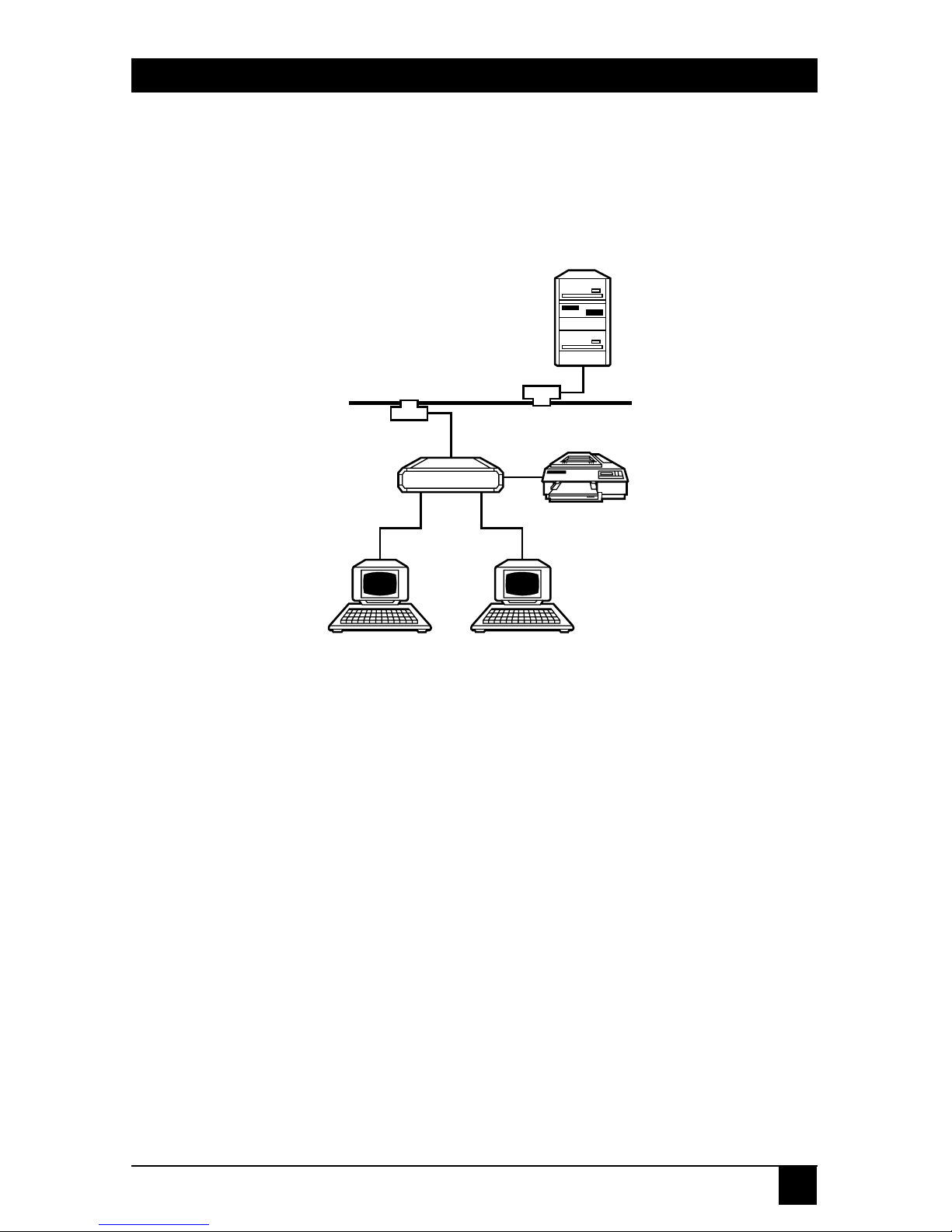
Figure 3-1. A Typical Terminal Server Layout.
The typical configuration shown in Figure 3-1 shows the Terminal Server
functioning as a primary interface between the local user (at a terminal, for
example) and the network. Even if the installation is far more complex, the
principles of initial hardware server and individual port configuration remain
the same.
Take care when connecting Terminal Servers to the Ethernet network.
You may need certain adapters and/or cables to connect all the individual
components of the Terminal Server subsystem (such as terminals, printers,
and modems). All the relevant information is provided in this manual.
Follow these three steps to setup the Terminal Server:
1. Physically setup the Terminal Server.
2. Configure the Terminal Server for first-time use.
3. Define individual ports.
Host
Ethernet backbone
Printer
Terminal
Server
TerminalTerminal
Page 20

20
TERMINAL SERVERS
3.1 Indicators of the Terminal Server
Table 3-1 describes the front and back panels, switches/buttons, and LED
indicators for each Terminal Server model.
Table 3-1. Terminal Server Indicators.
Model Buttons/Switches Power LEDs
2
LE2101A-R2 Power jack External 115-VAC PWR, LAN,
power supply
1
PORT, and
ERROR
LE2101AE-R2 Power jack External 230-VAC PWR, LAN,
power supply PORT, and
ERROR
LE2104A-R2, Power socket and 110-220 VAC, PWR, LAN, and
LE2204A-R2 Switch, Reset Button 50-60 Hz 4x port
LE2508A-R2, Power socket and 110-220 VAC, PWR, LAN, and
LE2608A-R2 Switch, Reset Button 50-60 Hz 8x port
NOTES
1
AC/DC, unregulated adapter with TUV, UL, or CSA approval.
Input: 220 VAC/50 Hz or 120 VAC/60 Hz
Output: 12 VDC, 800 mA, 9.6 VA
Cord: 5.5*2.1mm barrel, center negative
2
PWR—indicates that the unit is receiving power.
LAN—indicates network (LAN) activity.
PORT—indicates that the indicated port is already in use.
ERR—indicates that the power-on diagnostics check has detected
an error.
Page 21

21
TERMINAL SERVERS
Table 3-2. Power-On Diagnostic Indication.
Code Description
9 Base RAM test
8 N/A
7 N/A
6 N/A
5 N/A
4 TIMER test
3 LAN (Ethernet) test
2 NVRAM test
0 Power-On test completed. (If this flashes more
than twice, NVRAM has been restored to
default.)
Page 22

22
TERMINAL SERVERS
Table 3-3. Loader Indication.
Code Description
L The base unit has entered the software-
download state. A loader prompt is displayed on
the terminal where the INIT UPDATE command
was executed.
L (flashing) A new software module is currently being
downloaded into the base unit.
P Final phase of software downloading—updating
the FLASH memory.
— FLASH EPROM clearing (one segment moving
every few seconds).
Page 23

23
TERMINAL SERVERS
Table 3-4. Hardware Fault Indication.
Code Description
H The base unit Front End Processor (FEP) is not
responding.
d Inconsistency in DPRAM protocol version. Turns
to L and prompts the LOADER.
r Rebooting the Terminal Server (warm boot).
h High-rise FEP not responding.
j Jumper is set to Restore Factory defaults.
b Hardware problem in base FEP.
F Software error caused a processor fault.
Page 24

24
TERMINAL SERVERS
3.2 The Installation Process
3.2.1 U
NPACKING THE
T
ERMINALSERVER
Your package should contain the following items:
• Terminal Server
• This user manual
If anything is missing or damaged, contact Black Box at 724-746-5500.
3.2.2 S
ELECTING ALOCATION
Before installing the Terminal Server, verify that the chosen site meets the
following requirements:
• Select a clean location that is away from a heat source, such as direct
sunlight. Make sure the location is not near equipment that emits
electromagnetic interference (EMI) such as electric motors.
• Make sure that proper power outlets and network points are accessible.
• Allow for at least 4 inches (10 cm) clearance above and to all sides of the
unit for cable connections. Place the Terminal Server on a secure flat
surface.
• The ambient operating temperature for the Terminal Server is 32 to
122 °F (0 to 50 °C), at a relative humidity of up to 90%, noncondensing.
3.3.3 C
ONNECTING THETERMINALSERVER TO THE
LAN N
ETWORK
Connect the Terminal Server to the Ethernet network using the appropriate
networking procedures and cables for your configuration of the Terminal
Server port (RJ-45/UTP, BNC, or AUI) and site network (hub, transceiver).
NOTE
The LE2101A-BT-R2 and LE2101AE-BT-R2 automatically sense the
network topology (UTP or BNC). For this to function correctly, connect to
the network by plugging in the power before switching on the Terminal
Server.
Page 25

25
TERMINAL SERVERS
3.3.4 C
ONNECTINGSERIALDEVICES TO THETERMINALSERVER
You may connect any RS-232/RS-423 device to any of the serial ports of the
Terminal Server. This section describes the following procedures: connecting
DCE and DTE devices, pin layouts of the RJ-45 connector, and RJ-45 to DB25
or DB9 conversions.
Connecting DCE and DTE Devices
Two types of RS-232 devices can be connected to the Terminal Server serial
ports:
• DTE (Data Terminal Equipment) Devices—These are directly-attached
devices, such as terminals and computers, that provide data in the form
of digital signals at its output.
• DCE (Data Circuit Terminating Equipment) Devices—These are devices
that provide the functions required to establish, maintain, and terminate
connections and also provide the signal conversions required for
communication between a data terminal equipment and the telephone
line or data circuit. Modems connected to the serial port of the Terminal
Server in order to overcome the RS-232 50-ft distance limit are considered
to be DCE devices.
The Terminal Server serial ports act as individual DTEs. A simple and direct
pin-to-pin cable is required if such a serial port is to be connected to a
modem (similarly for any other DTE-to-DCE connection).
However, if terminals are connected directly to one another (in a DTE-toDTE configuration, since both the terminal device and the Terminal Server
port are DTEs), a special cable must be used. This cable, known as a “cross
cable” or “null modem cable,” includes crossed-connections between specific
RS-232 pins so that each DTE will recognize the other as a DCE.
Page 26

26
TERMINAL SERVERS
The RJ-45 Serial Port
All the Terminal Servers have RJ-45 connectors, which operate as RS-232 (or
RS-423) interfaces. Figure 3-2 describes the pin layout used in the RJ-45 ports.
1 2 3 4 5 6 7 8
1: Clear To Send (CTS) - input
2: Data Terminal Ready (DTR) - output
3: Transmit (TX+)
4: Transmit Return (TX-)
5: Receive Return (RX-)
6: Receive (RX+)
7: Data Set Ready (DSR) - input
8: Request To Send (RTS) - output
Figure 3-2. RJ-45 Serial Port Pinout.
Page 27

27
TERMINAL SERVERS
RJ-45 to DB25/DB9 (DTE) Conversion
Table 3-5 describes the cable wiring required for connecting a DTE device
(such as a terminal) with a RS-232 (DB9/25) port, to the Terminal Server’s
RJ-45 serial port.
Table 3-5. RJ-45 to DB25 (DTE) Conversion.
RJ-45 Pin RJ-45 Signal Name DB25 pin RS-232 DB9 pin
1* Clear to Send (CTS) 4 RTS 7
2* Data Terminal Ready (DTR) 6 DSR 6
3 Transmit (TX+) 3 RCV 2
4 Transmit Return (TX-) 7 GND 5
5 Receive Return (RX-) 7 GND 5
6 Receive (RX+) 2 XMT 3
7* Data Set Ready (DSR) 20 DTR 4
8* Request to Send (RTS) 5 CTS 8
Page 28

28
TERMINAL SERVERS
RJ-45 to DB25/DB9 (DCE) Conversion
The following table describes the cable wiring required for connecting a DCE
device with an RS-232, DB25 port (such as a modem) to a Terminal Server’s
RJ-45 serial port.
Table 3-6. RJ-45 to DB25/DB9 (DCE) Conversion.
RJ-45 Pin RJ-45 Signal Name DB25 pin RS-232 DB9 pin
1* Clear to Send (CTS) 5 CTS 8
2* Data Terminal Ready (DTR) 20 DTR 4
3 Transmit (TX+) 2 XMT 3
4 Transmit Return (TX-) 7 GND 5
5 Receive Return (RX-) 7 GND 5
6 Receive (RX+) 3 RCV 2
7* Data Set Ready (DSR) 6 DSR 6
8* Request to Send (RTS) 4 RTS 7
The pins marked with an asterisk (*) are required only for modem-control
or for flow-control, so you may ignore these pins when connecting a terminal.
For applications requiring DTR handshaking or for printers that use pin 11
for Printer Busy Signals, connect RJ-45 pin 1 (CTS) to DB25 pin 20 (for DTR)
or pin 11 (Printer Busy), respectively.
Page 29

29
TERMINAL SERVERS
The RJ-45 adapter does not support chassis ground but does supply signal
ground to both pin 4 and pin 5. The reason for this is that on many DB25
devices, pin 1 is left unconnected. In other cases, signal ground and chassis
ground are not electrically equivalent and connecting one to the other with a
cross-cable can potentially damage both devices. The Transmit Return (pin 4)
and Receive Return (pin 5) pins must be connected to signal ground (pin 7
on the DB25) when connecting an RJ-45 connector to an RS-232 connector.
The RS-232 and RS-423 standards specify a maximum length of cable that
may be used to connect devices. For example, the RS-232 specification for
9600 baud connections limits the cable length to 50 feet. In practice, the
50-foot limit is often exceeded and this may cause noise that may also lead
to interference and unpredictable results. When cabling directly from a
Terminal Server to an RS-423 terminal, use twisted pair cabling for maximum noise immunity. Using long flat cables may result in noise problems.
3.3 Power On Procedure and Diagnostics
3.3.1 S
INGLE-PORTTERMINALSERVER
Once the unit is powered, the power LED turns ON and the device goes
through initial “Power On” diagnostic tests. During these tests, which last for
approximately three seconds, all the unit LEDs should alternate ON and then
OFF. If a hardware failure is detected during any test, one or more of the
LEDs will flash at a constant rate. If this happens, call for technical support.
The PWR LED always remains ON when connected to power.
3.3.2 4-
AND
8-P
ORTTERMINALSERVERS
Immediately after the Terminal Server is powered on, it executes a “Power
On” diagnostic procedure and all of the LEDs on the front panel will flash. All
the LEDs light sequentially from left to right for approximately five seconds.
After the last LED has gone out, only the Power LED should remain on. The
entire diagnostic procedure lasts for approximately ten seconds. Normal
operation of the Terminal Server can commence once these diagnostics
complete successfully.\
If a diagnostic test reveals a fatal error, then all of the LEDs will light for a
few seconds. An error code will be indicated by leaving some of the port LEDs
ON. The display will then alternate between having all the LEDs on and the
error-code display. In the unlikely event of failure, contact technical support
for further assistance. If the diagnostic test reveals a non-fatal error (such as
the failure of a particular port), the Terminal Server will continue to operate.
Page 30

30
TERMINAL SERVERS
3.4 Restoring Factory Defaults
In rare cases where access to the Terminal Server is not possible and the
suspected cause may be incorrect configuration settings, or when you forget
the privileged password, you need to be able to restore the device to factory
defaults. A direct consequence of this step is that all configuration changes
made to the Terminal Server in the past will be lost (including the Internet
address which will default to 0.0.0.0) and the privileged password will be
restored to system.
The following sections describe the procedure to restore factory defaults
in all the different Terminal Server models.
3.4.1 S
INGLE-PORTTERMINALSERVER
1. Turn the power OFF by unplugging the terminal server power cable.
2. Remove the lid of the unit by pressing the four tabs.
3. Place the factory default jumper (JP2), located in the corner nearest the
PWR LED, on pins 1 and 2.
4. Plug in the power cord.
5. Wait until all the PORT and LAN LEDs flash (for a few seconds) and
unplug the power cord.
6. Return the factory defaults jumper (JP2) to pins 2 and 3.
7. Replace the lid and plug in the power cable. Factory defaults have now
been restored.
Page 31

31
TERMINAL SERVERS
3.4.2 4-
AND
8-P
ORTTERMINALSERVERS
1. Turn the power off and unplug the terminal server power cable.
2. Remove the upper lid by unscrewing the fastener at the back end of
the case.
3. Remove the printer-control printed circuit. This is the raised small
printed circuit to which a gray ribbon cable is connected. Unscrew its
mounting screw and carefully lift and disconnect the small board from
its socket connector.
4. Plug in the power cord and switch the power back on.
WARNING
Do not touch the power supply area. You might be shocked!
5. Wait until the LEDs display an error pattern (a sequence in which all
the LEDs light for a few seconds and finally display an error code).
6. Switch the power off, unplug the power cord, and replace the lid. Switch
on the unit by plugging in the power cord. Factory defaults have now
been restored.
Page 32

32
TERMINAL SERVERS
4. Configuration Guide
4.1 Introduction
This chapter explains how your system administrator can configure the
Terminal Server. Each section describes the required configuration for a
particular application of the Terminal Server. You only need to configure
the Terminal Server once, since it remembers the configuration setup when
it is powered off.
Carefully read through the general description issues and then refer to the
section that is best suited for your needs.
The description for each task in the following sections will contain:
• A general description of the major Terminal Server feature involved in the
task.
• A relevant example showing the required sequence of commands needed
to implement the feature. In each particular example, the most common
scenario is simulated.
• A thorough explanation of each statement in the example.
For more detailed information about the Terminal Server commands,
refer to Chapters 6, 7, and 8.
Page 33

33
TERMINAL SERVERS
Table 4-1. Quick Look-Up Table.
Environment Task Section Page
TCP/IP Basic setup of the TCP/IP Configuring IP
network interface of the parameters
Terminal Server
TCP/IP for Terminal Connecting a display Configuring
Server mode terminal terminal ports
Connecting a printer to the Adding TCP/IP
parallel port printers
Using BOOTP Using the
BOOTP protocol
TCP/IP for Remote Connecting remote stations Configuring SLIP
Access mode with SLIP Ports
Connecting remote stations Configuring PPP
with PPP Ports
Security Using RADIUS for Implementing
authentication RADIUS authen-
tication
Using the RADIUS Accounting using
accounting facility RADIUS
Management Using an SNMP agent Configuring the
SNMP agent
LAT Basic configuration of LAT Configuring LAT
services of the Terminal services
Server
Connecting a display terminal Configuring LAT
services
Connecting a printer LAT printers
Page 34

34
TERMINAL SERVERS
4.2 Access to Management Commands
After the successful installation of the Terminal Server, the next step is the
correct configuration of the unit so it can function as either a Terminal or
Remote Access Server. The system administrator should connect to the system
to configure the device. Please refer to the following sections for more
information.
When the Server is configured for the first time, it should be accessed by a
terminal connected to one of the serial ports of the server. Later, after an IP
address is initially defined for the server, basic configurations which need to
be entered or modified can be implemented remotely by the system
administrator who can now also access the server using Telnet or LAT
sessions. Once accessed, either from a directly-connected terminal or from
the network, the same command language is used for configuration and
operation of the server.
4.2.1 U
SINGPRIVILEGED
M
ODE
Many of the Terminal Server configuration commands require that the user
be in a special mode, known as privileged mode, which is equivalent to
becoming a superuser. This mode is initialized with the SET PRIV command
which prompts the user to enter a password. This protects the Terminal
Server from being configured by any unauthorized persons. Commands that
require privileged mode are disallowed for ordinary (not superusers) users
and any attempts to enter them results in a security violation error message.
The factory default password is system (in lower case). Once in privileged
mode, the system administrator can change this password to one of his own
choosing. The following example shows how an administrator, joe, changes
the password from the default system to peace.
Page 35

35
TERMINAL SERVERS
Terminal Server SW V4.1.3, HW V1.0
Enter username> joe
Local> SET PRIVILEGED
Password> system
Local> CHANGE SERVER PRIVILEGED PASSWORD
Password> peace
Verification> peace
Local>
Figure 4-1. Changing the System Password.
NOTES
The opening banner that appears when logging into the Server displays
valuable information about the model type and current software version.
When passwords are entered, they are not echoed on the display. You
need to verify the new choice once before it is accepted.
CAUTION
There is no way for the administrator to recall the privileged password if
its is forgotten. Keep a record of the password in a safe place. If the
password is forgotten, the administrator will have to restore the factory
default settings (see Chapter 3), which will discard all the configuration
changes made to the Terminal Server since initialization.
4.2.2 U
SING THEONLINEHELP
You can display brief descriptions of all Terminal Server commands and
characteristics available for the security level of your port by typing HELP at
the Terminal Server local prompt. The Terminal Server also offers limited
tutorial help that describes various end-user tasks. There are two online help
facilities:
• The HELP command—Provides an on-screen description of the chosen
command. Figure 4-2 shows an example.
Page 36

36
TERMINAL SERVERS
Local>HELP SET PORT SPEED
PORTS SPEED (INPUT/OUTPUT) (nonprivileged)
This nonprivileged option establishes the port speed in
bits per second (bps). Valid speeds include: 75, 110,
134,150, 3000, 600, 1200, 1800, 2000, 2400, 4800, 9600,
19200,38400, 57600, and 115200. The default port speed
is 9600.
The speed of each direction can be specified
independently.
INPUT SPEED specifies the speed from the device to the
Terminal Server. OUTPUT SPEED specifies the speed from
the Terminal Server to the device.
Restriction
*A port that is active in the AUTOBAUD process cannot
accept SPEED modifications.
Local>
Figure 4-2. The Help Command.
Page 37

37
TERMINAL SERVERS
• Automatic Command Completion (ACC)—While entering commands
and not sure of the next allowed command keyword, one can enter
a question mark ? in its place. The Terminal Server will respond
immediately with all the possible parameters available from that particular
point on. Note that non-privileged and privileged users will see different
listings when using the ACC facility because of their different respective
security levels.
After listing the possible parameters, the Terminal Server will automatically display a new prompt line with the initial command already in
place and with the cursor at the end of the preceding chosen keyword.
The Terminal Server now waits for the additional parameters to be
entered—which can include a further question mark.
Figure 4-3 shows the logical sequence of events in finding out from
the online help how to change the Terminal Server’s Internet address.
Local> SET ?
INTernet POrts SERVEr SNMP
SYstem TELnet BOotp AUTHentication
ACCounting
Local> SET INT ?
ADdress SUBnet MASk GATeway
HOSt NAme NAMEServer
Local> SET INT ad ?
NONe ip_address
Local> SET INT AD 111.222.222.111
Figure 4-3. Changing the Internet Address.
Page 38

38
TERMINAL SERVERS
ACC presents possible keywords as a combination of CAPITAL and small
letters. It is enough to enter just that portion of the command seen in capital
letters for it to be recognized by the Terminal Server. Therefore, INTERNET
can be abbreviated to INT and PORTS to PO.
If the whole parameter is in small letters (such as ip_address in the
previous example), then it should be entered as an equivalent value
(such as 111.222.222.111).
Page 39

39
TERMINAL SERVERS
4.2.3 C
OMMANDLINEEDITING/SPECIALKEYS
Several special keys may be used to facilitate the command entry process.
These keys can be used from any ANSI-compliant terminal. Table 4-2 displays
these keys and their functions.
Table 4-2. Special Keys Functions.
Key Function
Left and right arrow keys Moves the cursor along the current command
line to enable changes to be made.
Up and down arrow keys Scrolls through previous commands entered by
the user. Each arrow-up press will regress to a
previously entered command line. Similarly, an
arrow-down will progress to a more recently
entered command line (dependent on terminal
program).
<Backspace> or <Delete> Deletes the one character to the left of the
cursor.
<Ctrl/U> Deletes the current command line.
<Ctrl/Z> Operates like a <Ctrl/U> except when entered in
response to a password or verification prompt. It
stops the password-entering process (either the
password itself or the verification) and returns
the Terminal Server to local mode. If it is used in
response to a username prompt, it causes the
defined port name to be used for the specific
username. NOTE: <Ctrl/Z) does not unlock a
locked terminal (refer to the LOCK command).
<Enter> Executes the current command line.
Page 40

40
TERMINAL SERVERS
4.2.4 N
AMINGCONVENTIONS FORTERMINALSERVER AND FOR
LAT S
ERVICES
Some commands require you to enter a name, whether it is that of the
Terminal Server itself or a node, port, or service. All variable names must
consist of a string of between 1 and 16 characters and cannot be abbreviated.
The allowable characters are from A to Z, 0 to 9, $, - (hyphen), _
(underscore), and the . (period). The Terminal Server is not case-sensitive.
Terminal Server names must be unique to a local area network (LAN)
and port names must be unique within the Terminal Server itself. LAT service
names must be unique for each service on the LAN, but one service may be
offered by multiple service nodes.
These naming conventions do not apply to user names, Terminal Server
names or service identification messages.
4.2.5 C
OMMANDREQUIREMENTS ANDRESTRICTIONS
You can enter the Terminal Server commands in either uppercase or
lowercase characters, or a combination of both since the Terminal Server
is not case-sensitive. The words in a command line must be separated by one
or more spaces.
Command lines can contain up to 132 characters. You can continue a
command line onto a second terminal display line provided you do not press
the <Return> key at the end of the first display line. In local mode, there is no
such type-ahead facility.
You can interrupt current local mode output by pressing the <Break> key
or by entering your local switch character (discussed later). When a command
fails to execute, you get an error message. If you make an error in a command
line, the Terminal Server rejects the entire command line. If you get an error
message, check the command syntax and re-enter all or part of the command
as required. When a command has executed successfully, the Terminal Server
will display the local mode prompt.
Page 41

41
TERMINAL SERVERS
4.2.6 M
ANAGEMENTCOMMANDLANGUAGE
Commands may be entered in the Terminal Server in Local Mode. The
local mode is easily identified by the local prompt and cursor, Local>,
which appears once a connection is established with the server from either
a directly-connected terminal (in which case the operator needs to press the
<Enter> key twice) or via some form of remote network access (using either
Telnet or LAT). This mode allows the administrator to enter commands.
Each command line begins with a verb that instructs the server to perform
a specific operation. The two major categories of commands are:
• Management Command—Used to configure the Terminal Server. These
are implemented mainly by the system administrator. However, some
limited management commands are also available to an ordinary user.
Here, the relevant commands will affect the user’s own port only.
• User Commands—Used to operate the Terminal Server by ordinary
end-users.
Management Commands
Management commands are used to configure and verify the Terminal
Server setup. The three groups of commands are shown in Table 4-3.
Table 4-3. Management Commands.
Group Commands
(I) To add settings SET, DEFINE, or CHANGE
(II) To remove settings CLEAR or PURGE
(III) To verify settings SHOW or LIST
Page 42

42
TERMINAL SERVERS
Each command group affects either the Permanent Data Base (PDB)
or the Operational Data Base (ODB) setup of the Terminal Server.The PDB
resides in non-volatile memory so its contents are saved even without external
power connected to the Terminal Server. The ODB, however, resides in
regular RAM (Random Access Memory) which means that any changes made
to the ODB will be lost if the Terminal Server is disconnected from its power
source or is reinitialized in any other way.
When the Terminal Server is switched on, the contents of the PDB are
copies to the ODB. In fact, parameters associated with the serial and parallel
ports of the Terminal Server are copied from the PDB to the ODB each time
that port is accessed or disconnected.
Table 4-4 shows the confines of each management command: (A √
indicates that the specified database is influenced by the relevant command
while an X means that it is not influenced).
Table 4-4. Management Commands.
Operation Command PDB ODB
Configure Options DEFINE √ X
SET X √
CHANGE √√
View Configuration* SHOW X √
LIST √ X
Remote Configuration Options CLEAR X √
PURGE √ X
NOTE
Use the LIST command to view changes implemented by the DEFINE
command and use SHOW to view changes made by the SET command.
Page 43

43
TERMINAL SERVERS
4.2 Configuring Terminal Server Parameters
The initial setup of the IP environment in the Terminal Server involves
several key steps:
• Defining IP and/or LAT parameters—This involves the configuration of
the basic IP and/or LAT parameters of the Server’s network port. For IP
use, the IP address, subnet mask, gateway, DNS server need to be defined.
For LAT, the Terminal Server is ready immediately.
• Defining server wide characteristics—This involves Password enable,
authentication, Inactivity, ID-String, Broadcast.
• Defining port characteristics—This involves setting the access, speed,
flow control, signals, messages, Break, and a password.
• Defining session characteristics—This includes definition of the default
protocol, dedication, session-limits, auto-connect. For Telnet sessions
specifically, there is the definition of: CR translation, binary translation,
special characters, and for LAT sessions there are settings of groups,
queues, and services.
4.3.1 B
ASIC
IP S
ETUP
The following example illustrates the basic IP setup of the Terminal Server:
1. Local> CHANGE INTERNET ADDRESS 111.122.133.144
2. Local> CHANGE INTERNET MASK 255.255.255.0
3. Local> CHANGE INTERNET GATEWAY 111.122.133.155
NETWORK ANY
Figure 4-4. Basic IP Setup of a Terminal Server.
Step 1: Defines the IP Address
Statement 1 defines the IP address of the Terminal Server.
(In this example, 111.122.133.144).
Page 44

44
TERMINAL SERVERS
Step 2: Defines the Subnet Mask Information
Statement 2 defines the subnet mask information. If your configuration does
not use subnets, you will not need to define the mask value as the Terminal
Server will define the correct mask value according to the class of IP address.
Subnets divide one network into multiple smaller ones. This specifies that
this will not be a regular Class C address (up to 254 hosts) but rather that the
network ID portion will be extended by the first 3 bits of the fourth byte.
Step 3: Defines the IP Router (gateway)
Statement 3 defines the IP router (gateway) that will be used for transmitting
frames to stations outside the local network and builds the Routing Table of
the Terminal Server. The router IP address, in this example, is defined as
111.122.133.155. The ANY parameter specifies that IP frames to any network
will be transferred through this router.
You may add more entries to the Routing Table, specifying distinct
networks and hosts. Refer to Chapters 6, 7, and 8 for more information.
Step 4: Verify the IP Setup
The basic IP settings can be verified by using the commands: SHOW
INTERNET, SHOW INTERNET GATEWAY.
Note that if DEFINE is used as the verb in a configuration command, that
specific configuration will be available only after re-initializing the Terminal
Server. For this purpose, you would use the INIT DELAY 0 command.
Page 45

45
TERMINAL SERVERS
Figure 4-5 shows a sample output of the SHOW commands (SHOW may
be abbreviated as SH).
Local> SH INTERNET
Internet Address: 111.122.133.144
Subnet Mask: 255.255.255.0
Local> SH INTERNET GATEWAY
Gateway: 111.122.133.155 Network: 255.255.255.0
Figure 4-5. SHOW Commands.
4.3.2 D
OMAIN
N
AMESYSTEM
(DNS) S
ERVERSETUP
The Terminal Server may access a DNS (Domain Name Server) in order to
translate IP host names into IP addresses. This allows users to refer to hosts by
their names rather than by their addresses, while avoiding the need to update
the Host Table in each and every Terminal Server. For example:
1. Local> DEFINE INTERNET NAME RESOLUTION DOMAIN machine.test.com
2. Local> DEFINE INTERNET NAMESERVER sample ADDRESS 222.223.224.225
Figure 4-6. DNS Server Setup.
Step 1: Defines the Domain Name
Statement 1 defines the domain name in which the Terminal Server is
operating. This allows users to specify the default relative host name (when
referring to an address within the defined domain) and to omit the domain
name from each specific request.
Step 2: Defines the DNS Address
Statement 2 defines the specific IP address of the remote DNS server itself
(222.223.224.225 in the abov e example). It also specifies the DNS server
name to be sample (largely for display purposes). The Terminal Server can
hold 20 addresses in its built-in Host Table. If this table contains data, the
Terminal Server will first search it for name resolution before querying the
DNS server.
LOCAL> DEFINE INTERNET HOST machine2 ADDRESS 111.132.132.111
Page 46

46
TERMINAL SERVERS
Step 3: Verify the DNS Setup
Use the Show Internet Name Resolution command. The following shows the
output of these commands:
Local> SHOW INTERNET NAME RESOLUTION
Domain Name: MACHINE.TEST.COM
Resolution Host Limit: 32 Resolution Time Limit: 4
Resolution Mode: Ordered Resolution Retry Limit: 3
Nameservers:
222.223.224.225 SAMPLE.MACHINE.TEST.COM
Local>
Figure 4-8. Show Internet Name Resolution Command.
4.3.3 U
SING THEBOOTPPROTOCOL
Setting the Terminal Server IP parameters can be done based on its specific
hardware address (Ethernet MAC address). It is the BOOTP server that
provides the hardware-to-IP address resolution. With BOOTP, the network
manager can assign all the network IP addresses using only one file on the
BOOTP server. This also allows him to update the default router and DNS
server on all the devices from one centralized location. The BOOTP server
can run on any UNIX-based machine or PC running a suitable BOOTP
application.
On Power-On (or reset), the Terminal Server can search for a BOOTP
server on the local network and request a valid IP address for itself, for its
gateway and for its DNS server. These addresses will then be used and can also
be saved in non-volatile memory if required.
Page 47

47
TERMINAL SERVERS
The following is an example of configuring the Terminal Server to use
BOOTP:
1. Local> DEFINE BOOTP ALWAYS
2. Local> DEFINE BOOTP SAVE
3. Local> DEFINE BOOTP VENDOR NONE
Figure 4-9. Configuring the Server to use BOOTP.
Step 1: Defining when to use BOOTP
Statement 1 is used to configure the Terminal Server to make use of BOOTP
features every time it is powered on or reset. The Terminal Server will
broadcast a request onto the local network and if an online BOOTP server
responds with IP values, they will become the settings for the Terminal Server.
Step 2: Defining the Save Option
The IP parameters received from the BOOTP server are implemented with
immediate effect. These values will also be saved in non-volatile memory.
Statement 2 saves these values. Statement 3 specifies which BOOTP
extensions, if any, are to be used. See Chapters 6, 7, and 8 for more details.
4.4 Configuring Serial Ports
One can connect display terminals, printers, serial IP stations, and other
devices with asynchronous ports to any of the Terminal Server’s serial ports.
Each class of device requires a slightly different serial port configuration.
Please refer to the next sections for the correct setting for each application
of a serial port.
Page 48

48
TERMINAL SERVERS
A common use for Terminal Server ports is for connecting local terminals. There is an autobaud feature that attempts to configure a port with the
correct baud rate by analyzing the first two <Enter> key presses made by the
user before logging in. For devices that do not log in, such as printers, or for
low rates less than 1200 baud, this autobaud aid does not work. Ports required
to offer services should also have this feature disabled. Refer to the SET
PORT n AUTOBAUD command.
Multiple Characteristics in a Single Command Line: You may enter multiple
options in a single command line, restricted only by the 132 character limit.
For example, if you wish to set port 3 on the Terminal Server for not receiving
broadcast messages, even parity, and a port speed of 19200, you would type
the following command line at the local prompt:
Local> S ET PORT 3 BROADCAST DISABLED PARITY EVE N SPEED 19200
The SET PORT BROADCAST enables/disables messages from other
users. Another notable option used often for asynchronous ports include SET
PORT LOSS AUTHENTICATION which is used in low-speed connections to
notify the user in case of data loss.
Page 49

49
TERMINAL SERVERS
4.4.1 P
ORTNAMINGCONVENTION
Table 4-5 shows the names by which the PORT command refers to the serial
and parallel ports of the Terminal Servers.
Table 4-5. Port Naming Convention.
Model Port Type Name LAT Name
Single-Port Terminal Server Serial 1 N/A
4-Port Terminal Server Serial 1-4 PORT_1-PORT_4
4-Port Terminal Server Parallel PRINTER PRINTER_1
8-Port Terminal Server Serial 1-8 PORT_1-PORT_16
8-Port Terminal Server Parallel PRINTER PRINTER_1
4.4.2 S
PECIFYING APORTLIST
When specifying a port-list in a Terminal Server command, you can refer
either to a single port or to a range of ports (lowest-to-highest or vice-versa).
The parallel port is designated a name PRINTER. When setting port
characteristics with one or more options, the port-list can have embedded
spaces.
1 Local> DEFINE PORT 2 AUTOBAUD DISABLED SPEED 19200
2 Local> DEFINE PORT 2 CHARACTER 8 PARITY NONE STOP 1
3 Local> DEFINE PORT 2 FLOW CONTROL XON
Figure 4-10. Different Port List Methods.
In the example shown in Figure 4-10, statement 1 refers to ports 1, 2,
and 3—as well as the parallel port (of a 4- or 8-Port Terminal Server).
Page 50

50
TERMINAL SERVERS
4.5 Configuring Terminal Ports
The most common device used with the Terminal Server is the display
terminal. This section describes the serial port and other settings necessary to
configure the Terminal Server for connection of display terminals. Terminals
may be connected to the Terminal Server using one of two methods:
• Directly-Attached Terminal—The terminal is connected with a cross-cable
(or “null-modem cable”) to the serial port of the Terminal Server. The
Terminal Server supports either RS-232 or RS-423 standard automatically
(there is no need to configure for either). Verify that all cables in use are
within the maximum length specified by these standards.
• Modem-Attached Terminal—The terminal is connected via modem and
therefore, avoids the distance limitations mentioned above. The modem
may be asynchronous, leased-line, or any dialup modem. The modem
near the server port should be connected with a straight DCE cable to
the serial port of the Terminal Server.
4.5.1 P
HYSICALCHARACTERISTICS
—D
IRECTLY-ATTACHEDTERMINALS
The following examples show some common commands one can use when
configuring terminal ports. Although all of the examples refer to port 2, one
can configure more than one port in each command.
Figure 4-11 shows how to define the physical characteristics of the serial
port.
1. Local> DEFINE PORT 2 AUTOBAUD DISABLED SPEED 19200
2. Local> DEFINE PORT 2 CHARACTER 8 PARITY NONE STOP 1
3. Local> DEFINE PORT 2 FLOW CONTROL XON
Figure 4-11. Configuring a Port for a Directly-Attached Terminal.
Page 51

51
TERMINAL SERVERS
Step 1: Define the Port Speed
Statement 1 prevents the Terminal Server from sensing the speed used by
the specified port automatically. Rather, it specifies a forced baud rate.
NOTE
The port characteristics must match the settings of the terminal in order
for communications to work. Setting a baud rate of 19200 on the port and
using a terminal with a set baud rate of 9600 will not work.
One can also set different speeds for input (terminal-to-Terminal Server)
and for output (Terminal Server-to-terminal). This is done by entering
DEFINE PORT INPUT SPEED xxxx, and DEFINE PORT OUTPUT SPEED
yyyy.
Step 2: Define the Port Async Parameters
Statement 2 specifies the character size, parity setting, and number of stop
bits. This example shows the most common scenario sometimes referred to
in literature as 8-N-1 (8 bits per character, No parity, and 1 stop bit).
Step 3: Define the Port Flow Control
Statement 3 dictates that the port will use XON/XOFF flow control—also
known as software flow control. This is the most common case for directlyattached terminals. If this statement is entered, the attached terminal must
also be set to use the same flow control mechanism. You may also use other
methods of flow control. Other relevant configuration commands that may
apply here are DEFINE PORT FLOW CONTROL and DEFINE PORT LOSS
NOTIFICATION.
Page 52

52
TERMINAL SERVERS
4.5.2 P
HYSICALCHARACTERISTICS
—M
ODEM-ATTACHEDTERMINALS
The example in Figure 4-12 shows how to define the physical characteristics
of the serial port with a modem connection to a terminal.
1 Local> DEFINE PORT 3 AUTOBAUD DISABLED SPEED 19200
2 Local> DEFINE PORT 3 CHARACTER 8 PARITY NONE STOP 1
3 Local> DEFINE PORT 3 FLOW CONTROL CTS
4 Local> DEFINE PORT 3 SIGNAL CHECK ENABLED
5 Local> DEFINE PORT 3 SIGNAL CONTROL ENABLED
Figure 4-12. Configuring a Port for a Modem-Attached Terminal.
Step 1: Define the Port Characteristics
In statement 1, a fixed speed of 19200 baud is defined and in 2, the port
is defined as 8-N-1.
Step 2: Define the Port Flow Control
In statement 3, the recommended flow control mechanism for modemattached terminals—CTS/RTS—is implemented.
NOTE
CTS/RTS is a flow control between the Terminal Server and the attached
modem. The modem itself must be configured to use the same flow
control mechanism.
Step 3: Define the Modem Control Options
Statements 4 and 5 define the ability of the Terminal Server to work with the
RS-232 (or RS-423) signal lines (DTR and DSR signals). This feature allows
the host to log out a session if the modem disconnects and also to force the
modem to disconnect if the host itself ends a session. Enabling Signal Check
on a specific port will cause the Terminal Server to wait for an active DSR
signal before starting any data reception and to log out the port if the DSR
signal is inactive.
Enabling Signal Control will configure the Terminal Server to activate
DTR during an active session and to deactivate it when the port is logged out.
Page 53

53
TERMINAL SERVERS
4.5.3 O
PERATIONALCHARACTERISTICS
In addition to the physical characteristics defined in the previous section,
various operational characteristics may be defined for the ports.
Figure 4-13 shows examples that show several options that can be selected
for a terminal.
1 Local> DEFINE PORT 1 DEDICATED 111.112.113.114
2 Local> DEFINE PORT 1 PREFERRED 111.112.113.114
3 Local> DEFINE PORT 1 SESSION LIMIT 3
4 Local> DEFINE PORT 1 INACTIVITY LOGOUT ENABLED
5 Local> DEFINE PORT 1 TELNET CLIENT TERMTYPE vt220
Figure 4-13. Operational Port Options.
1. Defining the Port as Dedicated
Statement 1 defines the port as a dedicated port which means that it
prevents users from logging on to any other server than that specified
(111.112.113.114). By default, using a dedicated setting on a port makes
that port AUTOC ONNECT, disable BREAK, and allows a single session.
2. Defining the Port as Preferred
Statement 2 specifies a preferred host on the specified port. This is useful
when you need to allow the user to connect to any host, not necessarily from
the start, but with simplified access to a particular host. In Figure 4-13, the
user would only need to enter CONNECT with no further parameters, or
even just C, and the port would automatically Telnet to the preferred host
111.112.113.114.
If neither the DEDICATED nor the PREFERRED characteristics is predefined, the user will have to enter the full Telnet command and host name
or address as part of the CONNECT command.
Page 54

54
TERMINAL SERVERS
3. Defining the Maximum Number of Concurrent Sessions
Statement 3 limits the number of concurrent sessions permitted from the
port, in this example to three. It allows the user to open up to three sessions,
and to switch back and forth among them. The default is four sessions, but
users on DEDICATED ports are automatically set to a limit of one.
4. Defining an Inactivity Log-out Period
Statement 4 enables the inactivity logout facility. This automatically logs
off the user after a set period of idle time (set by the DEFINE SERVER
INACTIVITY TIMER command).
5. Defining the Type of Terminal Connected to the Port
Statement 5 defines the type of terminal connected to the port. This
information (vt220 in the example, which stands for the DEC VT220 display
terminal) is used during the opening stage of the Telnet session to advise the
host as to the type of terminal in use. Most UNIX applications will use this
information in order to determine the appropriate data stream for
communication with the terminal. The Terminal Server itself does not use
this information when communicating with the attached device nor does it
verify the validity of the name entered so any character string may be used.
This setting is optional. The default is ANSI.
Other configuration commands that may apply here are:
• DEFINE PORT BREAK LOCAL/DISABLED/REMOTE—this defines the
handling of a BREAK signal sent from the terminal to the Terminal
Server. There are three possibilities:
a. LOCAL specifies that the BREAK signal will be used to switch the user to
local mode. This is the default definition.
b. DISABLED specifies that the BREAK signal is to be ignored.
c. REMOTE causes the BREAK signal to be translated into a special Telnet
command that is sent to the host (TELNET BREAK) without affecting the
Terminal Server.
Page 55

55
TERMINAL SERVERS
• DEFINE PORT BROADCAST ENABLED/DISABLED—This
allows/disallows the port to display messages from any other ports.
Messages are sent using the BROADCAST command. (Default:
ENABLED)
• DEFINE PORT LOCK ENABLED/DISABLED—This allows/disallows
a user to lock his terminal (Default: ENABLED)
• DEFINE PORT PASSWORD ENABLED/DISABLED—This determines if
the global server password is required to log in to the specified port. This
password is set by the DEF SERVER LOGIN PASSWORD command and
applies to all the ports. If enabled, initial connection to a protected port
will display a single # and you have three chances to enter the password.
(Default: DISABLED and set to “access.”)
NOTE
This command should not be confused with PORT AUTHENTICATION,
which is used with RADIUS to fully authenticate specific users and
passwords.
• DEFINE PORT SECURITY ENABLED/DISABLED—This forces the port
into a secure status where only several non-privileged commands are
permitted. (Default: DISABLED—meaning that the port is not secured.)
• DEFINE PORT TELNET CLIENT—These parameters control the
behavior and options of the Telnet session initiated by the terminal
connected to the port. The default conditions are generally appropriate.
Reasons for change may include a need to prevent a special character
from being interrupted by the Terminal Server and to allow it to be sent
to the application. For further information, refer to Chapters 6, 7, and 8.
• DEFINE PORT USERNAME user_name—This associates a permanent
username to the port, eliminating the prompt-request usually displayed
on login. This parameter is overridden if the port login needs to be
authenticated by RADIUS.
• DEFINE PORT VERIFICATION ENABLED/DISABLED—This defines if
the Terminal Server will send messages to the attached device regarding
the connection, disconnection, or switching of sessions. (Default:
ENABLED)
Page 56

56
TERMINAL SERVERS
4.5.4 U
SINGSPECIALCHARACTERS
Certain specially-defined characters that are sent from a terminal attached to
a port are acknowledged by the Terminal Server as commands and, therefore,
are not forwarded to the user’s session. Occasionally, a specific application
will require that one or more of these characters should nevertheless be
forwarded since they have special meaning that can not be altered. In such
a case, these characters must be disabled or changed in the Terminal Server.
Table 4-6 lists functions of the Terminal Server that are set, by default,
to use specific characters. It shows the functions, the default keys that are
assigned to them and the commands that alter them.
NOTES
Some functions are defaulted to NONE.
The ^ refers to the Control-key that should be pressed together with the
subsequent letter.
Page 57

57
TERMINAL SERVERS
Table 4-6. Special Characters Functions.
Function Default Key Command
Resume connection with NONE PORT BACKWARDS SWITCH
previous session
Resume connection with NONE PORT FORWARD SWITCH
next session on the session
list
Switch to local mode NONE PORT LOCAL SWITCH
Send TELNET Abort Output ^O PORT TELNET CLIENT AO
(AO) request
Send TELNET Are-you-there ^T PORT TELNET CLIENT AYT
(AYT) request
Send TELNET Break (BRK) NONE PORT TELNET CLIENT BRK
request
Send TELNET End of Record ^Y PORT TELNET CLIENT EOR
(EOR) request
Send TELNET Interrupt ^Y PORT TELNET CLIENT IP
Process (IP) request
Send TELNET Synch ^X PORT TELNET SYNCH
(Synch) request
Page 58

58
TERMINAL SERVERS
4.5.5 L
OGICALCHARACTERISTICS
—LAT
The following example shows several logical options that are unique to
the LAT environment. You can add them to a terminal definition.
1 Local> DEFINE PORT 1 DEFAULT PROTOCOL LAT
2 Local> DEFINE PORT 1 AUTHORIZED GROUPS ALL ENABLED
3 Local> DEFINE PORT 1 DEDICATED r11at
Figure 4-14. Configuring Terminal—Logical Port Setup for LAT
Step 1: Define LAT as the Default Protocol
Statement 1 indicates that the primary use of the port will be for LAT sessions
(the default is Telnet). The Terminal Server will assume that all user requests
are for LAT services unless TELNET will be specifically indicated in the user’s
command.
Step 2: Define Authorized LAT Group for the Port
Statement 2 permits all LAT service groups to be available to this port. If this
command is omitted, only group 0 will be authorized. The user may later use
the PORT GROUPS command to restrict the authorized groups further and
to associate himself with only part of the groups. For example, when he uses
the SHOW SERVICES command, he will see only a partial listing of available
services, those that belong to his group. Statement 3 specifies that on this
DEDICATED port, the user is prevented from logging on to any host on the
network other than that specified.
Other configuration commands that may be used for LAT terminals are:
• DEFINE PORT LIMITED VIEW—This prevents the terminal user from
listing the LAT nodes and LAT services. (Default: DISABLED)
• DEFINE PORT NAME—This specifies a unique port name to the port.
Refer to the previous section for the list of default names.
• DEFINE REMOTE PORT MODIFICATION—This allows or prevents
a LAT service to change port characteristics. (Default: DISABLED)
Page 59

59
TERMINAL SERVERS
4.6 Accessing the Terminal Server from Remote/Network (Reverse-Telnet)
One can Telnet to the Terminal Server as well as to each of its specific ports,
including its parallel port, without needing separate IP numbers for each.
This allows you to share asynchronous devices such as modems and parallel
devices such as printers.
The Terminal Server is pre-configured with a Telnet listener function on
TCP port 23. Once a Telnet session is initiated to the Terminal Server on this
TCP port from any Telnet client, the user sees the same interface as if he was
accessing the server from a terminal connected directly to one of its serial
ports. This is useful for accessing the Terminal Server from a Telnet client
for management purposes.
The Telnet listener function is also associated with a TCP port in order
to differentiate between the serial ports of the Terminal Server, (bearing in
mind that the Terminal Server owns only one IP address and that several
printers may be connected at once). Therefore, there may be several Telnet
listeners defined on one specific Terminal Server, each listening on its own
TCP port and directing the information received by the session to a specific
serial or parallel port.
The Reverse Telnet (or Telnet Listener) service of the Terminal Server
may be used for many common applications:
• Connecting printers to the Terminal Server in a TCP/IP environment—
Terminal Server ports that are connected to printers are configured as
a Telnet listener. Hosts that need to print on these printers will use the
Telnet protocol to communicate with the Terminal Server.
• Communicating with serial devices from LAN stations—A Telnet listener
can also be configured to connect a Telnet client through the Terminal
Server to a specific serial (RS-232) device such as a modem.
In a specific case, the connecting Telnet client could be that of another
Terminal Server. In this case, its serial device connects and starts a Telnet
session on its behalf with a similar device. This is referred to as a back-toback application, and allows the transfer of serial traffic over TCP/IP
backbones.
Page 60

60
TERMINAL SERVERS
Figure 4-15 shows a typical configuration of a Telnet listener. Port 1 is
used in this example, but any port could be used, including the parallel port,
which is referred to as PRINTER.
1 Local> DEFINE PORT 1 ACCESS REMOTE AUTOBAUD DISABLE SPEED 9600
1 Local> DEFINE TELNET LISTENER 2001 PORTS 1 ENABLED
1 Local> DEFINE TELNET LISTENER 2001 CONNECTIONS ENABLED
2 Local> DEFINE PORT 1 TELNET SERVER NEWLINE TO TERMINAL <LF>
2 Local> DEFINE PORT 1 TELNET SERVER NEWLINE FROM TERMINAL<CRLF>
3 Local> DEFINE PORT 1 TELNET SERVER BREAK NONE
3 Local> DEFINE PORT 1 TELNET SERVER AO NONE
3 Local> DEFINE PORT 1 TELNET SERVER AYT NONE
3 Local> DEFINE PORT 1 TELNET SERVER IP NONE
Figure 4-15. Telnet-Listener—Possible Configuration Options.
1. Define the Port and set Telnet Listener
Statements 1 define the port as a REMOTE port and sets the baud rate
to 9600. You can also define a local port or a dynamic port to be a Telnet
listener. This access parameter only determines who can login and from
which end of the connection. The access itself is allowed regardless of the
Telnet Listener itself.
The AUTOBAUD mechanism cannot be used as the port would not
be able to receive the <Enter> keystroke required for automatic line-speed
regulation. The baud rate set here should be the same as that used by the
serial device connected to the port.
The Telnet listener function is also defined. The Telnet listener will wait
for incoming connection requests on TCP port 2001 and will redirect any
received data to the physical serial port 1 and vice-versa. Use a TCP port that
can be easily associated with the serial port used. The physical port number
and the TCP Port number are not actually dependent on one another. TCP
port 2001 is bound to physical port 1 above only for convenience. We could
have used TCP port 2007 for physical port 16.
Page 61

61
TERMINAL SERVERS
NOTE
More than one serial port can be configured using this command (a
rotary facility). If more than one port is defined and a session is started,
the server will direct the data to the first available port among those
defined. Each subsequent connection to the same port will be associated
with the next available port until all ports assigned to this listener are in
use.
Statements 2 designate a single or double character sequence which
is translated to a new line when received by the Terminal Server from the
terminal, or which is sent from the Terminal Server to the user terminal
after receiving a new line character sequence from the remote host.
2. Define the Telnet Server
Statements 3 specify that the Telnet server function used with this port will
disregard the following special Telnet signals: AO (abort output), AYT (Are
you there), BRK (Break), and IP (Interrupt Process). These are relevant to binary
communication and not always required. The BRK option is an important
one to point out because it specifies whether a local break request initiated
by the remote user is interpreted into a break at the Terminal Server port or
echoed through as a special character.
3. Verify the Configuration
The following steps need to be carried out in order to verify the configuration
of a Telnet listener:
1. Verify the configuration with the SHOW TELNET LISTENER command
as shown in Figure 4-16.
Local> SHOW TELNET LISTENER 2001
Listener TCP-port: 2001
Identification:
Ports: 1
Connections: Enabled
Local>
Figure 4-16. Show Telnet Listener Command.
Page 62

62
TERMINAL SERVERS
2. Connect the asynchronous device to the serial on which the listener
function has been defined (port 1 in the above example).
3. From any Telnet client that can reach the Terminal Server, open a Telnet
session with the Terminal Server. A typical command would be: telnet
CS_IP_address TCP_PORT, where CS_IP_address is the IP address of
the Terminal Server and TCP_PORT is the TCP port defined in the Telnet
Listener command.
4. After the connection is established, any data from the attached device is
transmitted to the network and back.
5. The same is applicable for the parallel printer port but it is unidirectional.
4.7 Configure LAT Services (Reverse LAT)
A LAT service may be defined in the Terminal Server to allow other LAT
hosts to create a session with the Terminal Server. The following applications
may necessitate reverse LAT services:
• Accessing the Terminal Server from another LAT node for management
purposes–A LAT service may be defined to allow access to the Terminal
Server itself. When a LAT session from any LAT node to the Terminal
Server is started, the same user interface is presented to the operator as if
he was accessing the server from a terminal connected directly to one of
its serial ports.
• Connecting printers to the Terminal Server in a LAT environment—
Terminal Server ports that are connected to printers should be
configured as a LAT service. Hosts that need to print will then start a
LAT session with the Terminal Server. Any combination of service names
together with the port they serve may be defined. More than one service
name can be defined and this name can then be used to access more than
one port.
• Communicating with serial devices from a LAT node—A LAT service can
be configured to connect other LAT nodes to any serial (RS-232) device.
In particular, the connecting LAT node can be another Terminal Server
that connects with a serial device and starts the LAT session on behalf of
these devices.
Page 63

63
TERMINAL SERVERS
The following examples show:
• Definition of a LAT service for accessing the Terminal Server.
• Definition of a LAT service for connecting a printer.
4.7.1 D
EFINE
LAT S
ERVICE FOR ANACCESSPORT
1 Local> DEFINE PORT 1 ACCESS REMOTE
2 Local> DEFINE SERVICE justaname CONNECTIONS ENABLED
3 Local> DEFINE SERVICE justaname PORTS ACCESS
Figure 4-17. A LAT Service Accessible Port.
1. Definition of a Port
Statement 1 defines port 1 with the ACCESS REMOTE characteristic, allowing
it to be accessed from the LAN.
2. Definition of the LAT Service
Statement 1 and 2 define a new LAT service called justaname and enable it.
Moreover, statement 3 defines it as an access service, which means that a user
initiating a session to this service will be communicating with the Terminal
Server itself, rather than a serial port (as in Figure 4-18).
Page 64

64
TERMINAL SERVERS
4.7.2 D
EFINING A
LAT S
ERVICE FOR ASERIALPORT
3 Local> DEFINE SERVICE justaname PORTS 1 ENABLED
Figure 4-18. LAT Service for a Serial Port.
If Statement 3 from the previous example is replaced by the one above,
associate it with serial port 1.
Other configuration commands that may apply here are:
• DEFINE SERVICE PASSWORD—This assigns a password to a LAT service.
The LAT node that would access that service must submit this password.
• DEFINE SERVICE QUEUE ENABLED/DISABLED—This indicates the
use of the LAT queue facility. When this option is enabled, any request
for a LAT session to the service will be queued and attended to on a FIFO
(First-In, First-Out) basis.
4.8 Configuring Printer Ports
4.8.1 A
DDING
TCP/IP P
RINTERS
The process of configuring a printer in a TCP/IP environment involves two
key steps:
• Definition of a Telnet listener function to the port where the printer is
connected.
• Defining the printer in the host printing system by having it use either
Telnet or the compatible prtcp program as the printing program.
A Telnet listener is defined in the Terminal Server and a printer is
defined in the UNIX system. The UNIX printer is directed to use a script and
the script is executed with a Telnet command. When a print job is sent by
UNIX, a Telnet session is established and the data is sent to the Terminal
Server. The Terminal Server, based on the TCP port used in the session, will
pass the data either to the serial or to the parallel port defined in the TelnetListener command. UNIX may use either the original Telnet program or the
prtcp program. The same parameters are used in either.
Page 65

65
TERMINAL SERVERS
Host Definition
Copy the downloaded PRTCP.C source and MAKEFILE executable files to
your UNIX system and compile using the given MAKEFILE. You may have to
change the library file you link with to fit your Operating System. Then, follow
the relevant instructions for your UNIX to complete the procedure.
Sun Os
Perform the following steps for each printer:
1. Edit the /etc/printcap file to include a queue named CSqueue
(for example):
CSqueue|CSqueue:\
:lp=/dev/null:sd=/usr/spool:of=/etc/CSprint
2. Create the /etc/CSprint shell script:
#!/bin/csh -f
telnet 130.34.28.10 2007
You can now use the following standard command for printing:
LPR -PCSqueue file_name
Where CSqueue is the queue defined in step 1, and file_name
is the file to be printed.
IBM AIX
Follow these steps for each printer:
1. Define a printer device:
cp/dev/null/dev/printer_name
chmode 666/dev/printer_name
2. Define the printer to the AIX system:
smit mkvirptr
3. Choose 1 on the menu shown to determine where the printer will
be attached.
4. Specify the device defined in the previous step (printer_name).
Page 66

66
TERMINAL SERVERS
5. When defining the queue name, choose a name other than the printer
name.
6. Answer any other questions relevant to the printer attached.
7. Create a script file with the following script:
#!/bin/sh
/usr/lib/lpd/piobe $*|telnet IP_address_of_Passaport TCP_port
This will be the “back-end shell script” for the printer. It uses the piobe
program (standard AIX printing program) and pipes the results to a Telnet
program that drives the information to the Terminal Server.
If prtcp is used, replace the Telnet program in the above script with prtcp.
Note that in this case, you must start the STREAMS environment of the AIX,
by executing the strload command. Refer to the AIX documentation regarding
PSE (Portable STREAMS Environment) for more information on the
STREAMS environment. The prtcp program uses the TLI system services
provided by PSE.
8. Make the script executable:
chmod +x backend_file_name
9. Define the script the AIX system by:
smit chquedev
10. Choose the printer and queue defined earlier and edit the “backend
program path name” to contain the script created in step 7.
11. Use the lp -d printer_name command to print.
HP/UX
Page 67

67
TERMINAL SERVERS
1. Define a printer using the program sam, specifying /dev/null as the
printer device, or use the following command:
/usr/lib/lpshut
/usr/lib/lpadmin -pprinter_name -v/dev/null -minterface_script_file
/usr/lib/lpsched
Replace printer_name with a name of your choice.
The above command will also create a script file at
/usr/spool/interface/printer_name.
2. Replace the script by the following script:
cat $6 | telnet IP_address_of_Passaport TCP_port
3. If prtcp is used, replace the Telnet program in the above script by prtcp.
4. The script will pipe the printed data through the Telnet command to the
IP address of the Terminal Server and to the TCP port defined in the
Telnet listener command at the Terminal Server.
5. Restart the lpsched process by executing lpshut and lpsched so that the new
definition will be used.
6. Use the accept and enable commands (both with the printer name as a
parameter) to make the printer available.
7. The printer is now ready to print.
SCO
Page 68

68
TERMINAL SERVERS
1. Define a printer using the sysadmsh program, specifying /dev/null as the
printer device, or use the following command:
/usr/lib/lpadmin -p printer_name -v /dev/n
Replace printer_name by a name of your choice.
2. The following command will create a script file at
/usr/spool/lp/admins/lp/interfaces/printer_name
3. Replace the script by the following script:
cat $6 | telnet IP_address_of_Passaport TCP_port
4. If prtcp is used, replace the Telnet program in the above script by prtcp.
5. The script will pipe the printed data through the Telnet command to the
IP address of the Terminal Server and to the TCP port defined in the
Telnet listener command at the Terminal Server.
6. Restrat the lpsched process (by executing lpshut and lpsched)so that the
new definition will be used.
7. Use the accept and enable commands (both with the printer name as a
parameter) to make the printer available.
8. The printer is now ready to print.
4.8.2 LAT P
RINTERS
The process of configuring a printer in a LAT environment involves two steps:
Page 69

69
TERMINAL SERVERS
• Definition of a LAT Service function on the port where the printer is
connected (refer to Defining LAT Services)
• Definition of the printer in the host printing system
VMS
The following describes the VMS procedure needed in order to define a
Terminal Server port as a printer.
$ RUN SYS$SYSTEM:LATCP
LCP> CREATE PORT port_name/APPLICATION
LCP> SET PORT port_name/NODE=node_name/SERV=serv_name
LCP> EXIT
$ SET DEVICE/SPOOL=(queue_name, SYS$SYSDEVICE) port_name
Figure 4-19. VMS Procedure.
In this example:
• serv_name is the name of the LAT service defined on the Terminal Server
for the printer
• node_name is the node name of the Terminal Server. The Terminal Server
does not have a default name but this may be changed by using the
DEFINE SERVER NAME command (see Advanced LAT Definitions).
• queue_name is the name of the VMS queue created and initiated by this
procedure
• port_name is of LATxxxx
4.9 Advanced LAT Definitions
The Terminal Server does not require any special definitons in order to work
in a LAT environment. LAT, being both dynamic and specifically designed
for terminal server environments, is very easy to operate and use. However,
Page 70

70
TERMINAL SERVERS
several configuration commands are available in order to enhance control
over LAT functionality.
The following list shows some of these commands. A complete list can be
found in Chapters 6, 7, and 8.
• DEFINE SERVER NAME—This allows you to change the Terminal Server
default name which is CS_xxxxxxxxxxxx, where the 12 xs are the
hexadecimal representation of the Terminal Server Ethernet MAC
address. This value may be changed to facilitate the definition of the
server in other systems (such as when defining printers for VMS hosts).
• DEFINE SERVER CIRCUIT TIME nnn—This defines the time interval
between consecutive messages sent by the Terminal Server to the LAT
services. The range allowed is between thirty to two hundred milliseconds.
The default is 80 milliseconds.
• DEFINE SERVER KEEPALIVE TIMER nnn—This defines the interval
between consecutive messages sent for maintaining a LAT session—when
there is no data to transmit. The allowed range is 10 to 180 seconds. The
default is 20 seconds. Modifying this value may effect the amount of traffic
on the local network.
4.10 Advanced Telnet Definitions
The Terminal Server has a group of commands relating to a specific port
as a TELNET CLIENT and another for a port as a TELNET SERVER. It is
important to distinguish between the two:
• The SET PORT TELNET CLIENT commands change the Telnet client
characteristics for the specified port as these commands relate to new
Telnet connections established from the specified port.
• The SET PORT TELNET SERVER commands change the Telnet server
characteristics for the specified port as these commands relate to new
Telnet connections established to the specified port.
A TCP/IP host can translate data transferred during Telnet in several ways
and some of the Telnet protocol parameters can be changed using the Telnet
Option Negotiation procedure in order to facilitate this.
Page 71

71
TERMINAL SERVERS
4.11 Configuring SLIP Ports
The Terminal Server can be used to connect SLIP devices to an IP network.
The SLIP (Serial Link Internet Protocol) protocol is a simple implementation
of the IP protocol over Asynchronous links. The SLIP device can be a PC,
workstation, router, or any other device connected through a serial port to
the Terminal Server.
Any SLIP device must be assigned a unique IP address which must be
part of the same subnet to which the Terminal Server is connected.
The following example shows a sample configuration of a port which will
be used for a SLIP connection.
1 Local> DEFINE PORT 2 AUTOBAUD DISABLED SPEED 19200
2 Local> DEFINE PORT 2 DEDICATED SLIP
3 Local> DEFINE PORT 2 SLIP ENABLED
4 Local> DEFINE PORT 2 FLOW DISABLED
5 Local> DEFINE PORT 2 SLIP HOST 111.122.133.144
6 Local> DEFINE PORT 2 USERNAME “SLIP 2”
Figure 4-20. Configuring a Port for a SLIP Connection.
Step 1: Define the Port Characteristics
Command 1 defines a fixed speed (of 19200 baud) unlike for directlyattached terminals.
Step 2: Define port as Dedicated SLIP and Enable it
Statement 2 specifies that the port will be attached automatically as a SLIP
host when the user logs on to the Terminal Server. DEDICATED prevents
the user from using the port as a terminal port and negates the need for any
character-mode communication—except the user name and password (if
needed). This simplifies the script required to connect the SLIP device to
the Terminal Server.
Statement 3 enables the port to work in SLIP mode. To enter SLIP mode,
the user issues a “CONNECT SLIP” command or uses the Dedicate definition
as in statement 2. After starting the SLIP mode, the Terminal Server will
expect only SLIP frames from the attached device.
Page 72

72
TERMINAL SERVERS
Step 3: Define the Port Flow Control
We recommend that you disable flow control for directly-attached devices
with SLIP connections, such as when a modem is used. Command 2 disables
the flow control that is implemented by the SLIP itself. Note that the
XON/XOFF mechanism must not be used for SLIP connections.
Step 3: Define the SLIP Port Address
Statement 5 configures the IP address of the port. The IP address can be
configured on the port in one of three different methods:
• Configuration by using the Terminal Server command language (as in
the example above)
• Configuration by a RADIUS server
• Configuration learned during the session, using the first SLIP frame
coming from the device
Step 4: Define the Port User Name
Statement 6 defines a permanent user name to the port eliminating the
request-prompt usually displayed when the user logs in. This setting is
overridden if the port log-in is to be authenticated by a RADIUS server.
U
SINGCOMPRESSED
SLIP
Compressed SLIP is an improvement on the regular SLIP protocol. Since IP is
a protocol used on a network with many devices and SLIP is a protocol used
between only two devices, the IP header contains a lot of data that is now
redundant. This data causes a waste of bandwidth when traveling over slow
links—a loss that can be countered. The Van-Jacobson Compression method,
when supported by both the Terminal Server and the attached device, can
save this TCP overhead. The CSLIP protocol can manage up to 16 concurrent
TCP/IP sessions.
The following example shows how to add CSLIP capability to a pre-defined
SLIP port.
Page 73

73
TERMINAL SERVERS
1 Local> DEFINE PORT 3 SLIP COMPRESSION ENABLED
2 Local> DEFINE PORT 3 SLIP COMPRESSION AUTOCOMPRESS
3 Local> DEFINE PORT 3 SLIP COMPRESSION STATES 16
Figure 4-21. Configuration of a CSLIP Port.
Step 1: Define the Port Characteristics
Statements 1 and 2 set the post-SLIP mode as CSLIP. When using command 1
to implement TCP/IP through the port, the remote node connected to the
port must also support the CSLIP protocol. With command 2, the Terminal
Server checks the first IP packets received from the node and uses the CSLIP
only if initiated by it.
Step 2: Define the Port CSLIP States
Statement 3 defines the maximum number of CSLIP states to be used on the
port. The Van-Jacobson compression method uses a STATE data-structure for
each concurrent TCP connection. This parameter can limit the number of
states. Valid values are between one and sixteen. The default is 16 states.
4.12 Configuring PPP Ports
The Terminal Server can be used to connect devices to the IP network using
PPP (Point-to-Point Protocol). The IP-over-PPP protocol uses the standard
PPP Link Control Protocol (LCP) to determine the data-link connection and
Page 74

74
TERMINAL SERVERS
the IP Control Protocol (IPCP) to establish and configure the network-layer
protocol. The PPP device can be a PC, workstation, router or any other device
connected through a serial port to the Terminal Server. (For detailed
information on both LCP and IPCP, refer to RFC1331 and RFC1332—both
available on the Internet.)
Any PPP device must be assigned a unique IP address. This IP address must
be a part of the same subnet to which the Terminal Server is connected.
The following example shows how to define the characteristics of a port for
PPP connection.
1 Local> DEFINE PORT 1 AUTOB DISABLED SPEED 19200
2 Local> DEFINE PORT 1 DEDICATED PPP
3 Local> DEFINE PORT 1 PPP ENABLED
4 Local> DEFINE PORT 1 FLOW DISABLED BREAK DISABLED
4 Local> DEFINE PORT 1 SIGNAL CONTROL ENABLED SIGNAL CHECK ENABLED
5 Local> DEFINE PORT 1 PPP IPCP HOST 111.112.113.114
6 Local> DEFINE PORT 1 USERNAME “PPP 1”
Figure 4-22. PPP Port Configuration.
Step 1: Define the Port Characteristics
Command 1 defines a fixed speed (of 19200 baud) unlike for directlyattached terminals. Note that AUTOBAUD cannot be performed on
PPP frames.
Page 75

75
TERMINAL SERVERS
Step 2: Define Port as Dedicated PPP and Enable it
Statement 2 specifies that the port will be attached automatically as a PPP host
when the user logs on to the Terminal Server. DEDICATED prevents the user
from using the port as a terminal port and negates the need for any charactermode communication—except the user name and password (if needed). This
simplifies the script required to connect the PPP device to the Terminal
Server.
Statement 3 enables the port to work in PPP mode. To enter PPP mode, the
user issues a “CONNECT PPP” command or uses the Dedicated definition as
in statement 2. After starting the PPP mode, the Terminal Server will expect
only PPP frames from the attached device.
Step 3: Define the Port Flow Control
We recommend that you disable flow control for directly-attached devices
with PPP connections, such as when a modem is used. Command 4 disables
the flow control that is implemented in any case by the PPP itself.
Step 4: Define the Port IPCP Address
Statement 5 configures the IP address of the port. The IP address can be
configured in one of three different methods:
• Configuration using the Terminal Server command language
(as in this example)
• Configuration by a RADIUS server
• Learning during IPCP negotiation with the connected device
Step 5: Define the port user name
Statement 6 defines a permanent username to the port eliminating the
request-prompt usually displayed when the user logs in. This setting is
overridden if the port log-in is to be authenticated by a RADIUS server.
4.12.1 U
SINGADVANCED
PPP P
ARAMETERS
The following example shows some additional and more advanced settings
available for a PPP defined port. In this example, the same Terminal Server as
in the previous example is configured for a modem connection, but also has
additional settings to restart the LCP protocol if the connection restarts and
Page 76

76
TERMINAL SERVERS
to compress PPP fields. It also forces the node to use a pre-configured IP
address on the port.
1 Local> DEFINE PORT 1 CHARACTER 8 PARITY EVEN STOP 1
2 Local> DEFINE PORT 1 PPP IPCP COMPRESSION ENABLED
3 Local> DEFINE PORT 1 PPP IPCP COMPRESSION STATES 8
4 Local> DEFINE PORT 1 PPP IPCP ADDRESS ENABLED
5 Local> DEFINE PORT 1 PPP LCP ACFC ENABLED
6 Local> DEFINE PORT 1 PPP LCP PFC ENABLED
7 Local> DEFINE PORT 1 PPP LCP MAP 000A0000
Figure 4-23. Advanced Settings for a PPP Defined Port.
1: Definition of Port Communication Parameters
Statement 1 defines the general communication parameters dealing with bits
per character, parity and stop bits.
2: PPP IPCP Compression Settings
Statements 2 through 4 specify the IPCP settings. This includes the use of
Van-Jacobson compression (2) where the IPCP enables the nodes to negotiate
the use of this compression method to reduce the overhead of the TCP/IP
headers. Statement 3 specifies the number of TCP connections that the
Terminal Server can decompress from the peer at any given time while 4
specifies that the Terminal Server should attempt to negotiate the IP address
for both ends of the link. If the negotiation is rejected, the IP layer will fail
to open.
3: PPP LCP Compression Settings
Command 5 deals with PPP Address and Control Field Compression and
affects the HDLC frames at the Link Layer. These frames include address and
control bytes that are obsolete on a PPP link. 5 causes the Terminal Server to
negotiate for the omission of these fields during the establishment of a LCP
connection.
For PPP links that are used only to connect two stations and that use a
single Data-Link Protocol (IP in the Terminal Server case), Protocol Field
Compression can reduce the overhead on the PPP frames. Command 6
enables the compression of the PPP Protocol Field.
Page 77

77
TERMINAL SERVERS
Statement 6 says that the Terminal Server should invoke PPP Link Control
Protocol (LCP) frames after the port is logged on. In this example, the LCP
Configuration request starts after the modem is connected and DSR is active.
Statement 7 deals with changing the default Async-Control-Character-Map
(ACCM) and causes the Terminal Server to perform byte-stuffing on the bytes
representing XON/XOFF. This command prevents the Terminal Server from
sending through any character that could be wrongly translated by the
modem as flow control characters.
For passive PPP devices as control devices that need to be reconnected after
any loss of connection, you should use the DEF PORT n PPP UP PASSIVE
DISABLE command.
4.12.2 V
ERIFYING
PPP P
ORTCONFIGURATION ANDSTATUS
The Terminal Server PPP configuration and status can be verified using the
SHOW PORT PPP commands.
A PPP connection starts with the LCP layer establishing the Data Link layer.
Page 78

78
TERMINAL SERVERS
The following example displays the port’s LCP configuration.
Local> SHOW PORT 1 LCP CHARACTERISTICS
Port 1: PPP 1 Server: CS_0020d207090
LCP Characteristics:
LCP: Enabled
Passive Open: Enabled
Restart Timer: 3 seconds
Max Configure: 10 transmissions
Max Terminate: 2 transmissions
Max Failure: 10 transmissions
LCP Options: Local:
MRU: 1500
Character Map: FFFFFFFF
Authentication: None
Link Quality: Disabled
Magic Number: Disabled
PF Compress: Disabled
ACF Compress: Disabled
FCS Size: 16 Bit
Figure 4-24. LCP Configuration for a Port.
Page 79

79
TERMINAL SERVERS
To find out the current state of a link, you can check the LCP status:
Local> SHOW PORT 1 LCP STATUS
Port 1: PPP 1 Server: CS_0020d2070790
LCP Status:
State: Opened
Authentication: None
LCP Options: Local:
MRU: 1500
Character Map: FFFFFFFF
Authentication: None
Link Quality: Disabled
Magic Number: Disabled
PF Compress: Disabled
ACF Compress: Disabled
FCS Size: 16 Bit
Figure 4-25. Checking the LCP Status.
Page 80

80
TERMINAL SERVERS
The negotiation of IPCP starts after the Link Layer is established and the
LCP state is OPENED. The following example asking to verify the IPCP
configuration displays an IPCP valid configuration.
Local> SHOW PORT 1 ICPC CHARACTERISTICS
Port 1: PPP 1 Server: CS_0020d2070790
IPCP Characteristics:
IPCP: Enabled
Passive Open: Disabled
Restart Timer: 3 seconds
Max Configure: 10 transmissions
Max Terminate: 2 transmissions
Max Failure: 10 transmissions
IPCP Options: Local:
Negotiate Address: Enabled
Remote IP Address: 111.112.113.114
Compress Header: Disabled
Compress States: 16
Figure 4-26. Verifying the IPCP Configuration.
To find out the current state of the IPCP layer, check the IPCP status as
follows:
Local> SHOW PORT 1 IPCP STATUS
Port 1: PPP 1 Server: CS_0020d2070790
IPCP Status:
State: Opened
Since Open: 0 02:12:08
IPCP Options: Local:
Negotiate Address: Enabled
IP Address: 111.112.113.114
Compress Header: Disabled
Compress States: 0
Figure 4-27. Checking the IPCP Status.
Page 81

81
TERMINAL SERVERS
4.13 Configuring Security Options
4.13.1 U
SERSECURITY
L
EVELS
Three levels of security are available for Terminal Server ports:
• Privileged status—The user at a privileged port has access to the entire
Terminal Server command set including commands that manage the
Terminal Server, its ports, its sessions, and its services.
Any user who knows the privileged password can set a port’s status to
privileged with the SET PRIVILEGED command. For security reasons,
a Terminal Server usually has only one privileged user—the person
managing the Terminal Server.
• Non-privileged status—Non-privileged status is the default for all
interactive ports. Users at a non-privileged port cannot access commands
that change the state of the Terminal Server or other ports, but they can
use all commands required for connecting to LAT services and Internet
hosts from an interactive port.
Non-privileged users can also modify certain port characteristics and
display information about the Terminal Server, its port, and service
nodes.
• Secure status—Secure status restricts the commands that are available on
a port to a subset of the non-privileged commands. This subset includes
commands that are required for connecting to Telnet services and
Internet hosts from that particular port. Secure users have access to only
limited display information and cannot use the broadcast feature that is
available to non-privileged users. Also, secure users cannot use CHANGE
and DEFINE commands (only the SET keyword is valid).
All commands that you can enter from a secure port are identified in
Chapters 6, 7, and 8, by the designation “secure.” To view all secure
commands, issue the SET PORT SECURITY ENABLED command and
then access the Terminal Server online help. The commands listed will
be those available to secure users.
Page 82

82
TERMINAL SERVERS
4.13.2 C
ONVENTIONS FORSPECIFYINGPASSWORDS
Unless otherwise stated, all passwords consist of between one and sixteen
ASCII characters. When specifying passwords in Terminal Server commands,
either enclose the password in quotation marks and include it in the
command line, or enter the command without the password and let the
Terminal Server prompt you for it. You can omit the password value and be
prompted for it only in the case where the password characteristic is the only
characteristic in the command line. Note that passwords are case sensitive, for
example, “SYSTEM” and “system” are different.
The Terminal Server does not echo a password that is entered in response
to a password prompt. When you specify a new password, the Terminal Server
displays a verification prompt and waits for you to re-enter the password
(which again is not echoed). If both entries match, the password is approved
and the local mode prompt is displayed. If the password is rejected, the
Terminal Server returns to the local mode prompt. You can press <Ctrl/Z>
at any time to interrupt password processing and return to the local mode
prompt.
You can change the Terminal Server characteristics LOGIN PASSWORD
and PRIVILEGED PASSWORD, but you cannot clear them; you can change
or clear the service characteristic PASSWORD and the Terminal Server
characteristic ACCESS PASSWORD.
To clear a service password, specify quotation marks with nothing in
between them (“ ”) in place of the password in the command line.
The privileged mode of the Terminal Server is password protected.
Please refer to Using Privileged Mode for further information.
Page 83

83
TERMINAL SERVERS
4.13.3 U
SING AGENERALPASSWORD
A general password may be defined for the Terminal Server and both
enabled or disabled per port. If a serial port is defined with the PASSWORD
characteristic, then each log-in operation to this port will prompt the user
(with a #) to enter a valid general password. Once the password is entered
and verified, the user will then see the usual Terminal Server startup screen.
The following example shows how to protect port 1 with a general
password.
1 Local> DEFINE SERVER LOGIN PASSWORD secret
Password>secret (not echoed)
Verification> secret (not echoed)
2 Local> DEFINE PORT 1 PASSWORD ENABLED
Figure 4-28. Protecting Port 1 with a General Password.
Statement 1 sets the server log-in password as “secret.” This is a global
password and each port defined with the PASSWORD characteristic (as in
statement 2) will use the same password.
When a user connects to port 1 and tries to log in, he will be prompted to
enter the correct server password (with a # prompt).
4.14 Authentication—Using RADIUS
RADIUS (Remote Authentication Dial In User Service) is a system of
distributed accounting and security that both secures remote access to
networks and network services against unauthorized access and monitors
the accounting activity of sessions. RADIUS security includes two pieces: an
authentication server and client protocols. The server is installed on a central
computer at the customer’s site. The client side is implemented in the
Terminal Servers.
RADIUS is designed to simplify the security process by separating security
technology from communications technology. All user authentication and
network service access information is located on the authentication, or
RADIUS, server. This information is contained in a variety of formats suitable
to the customer’s requirements. RADIUS in its generic form will authenticate
users against a UNIX password file, Network Information Service (NIS), as
well as a separately maintained RADIUS database.
Page 84

84
TERMINAL SERVERS
Terminal Servers working with modems operate as RADIUS clients. The
RADIUS client sends authentication requests to the RADIUS server which
responds accordingly.
The protocol defines two entities:
• RADIUS Client—a device that needs authentication services. The
Terminal Server, for example, functions as a RADIUS client.
• RADIUS Server—a device that receives authentication requests from
RADIUS clients and responds either with Accept (authentication
validated) or Reject (authentication failed). The RADIUS server is usually
implemented on UNIX workstations and is downloadable as free public
domain for most UNIX and also for Windows NT operating systems.
The RADIUS clients communicate with the RADIUS server using UDP.
Many separate RADIUS clients may use the services of a single RADIUS server,
even when the server is connected to a different network. The fact that the
RADIUS server can be centralized allows the system administrator to define
the users and password data bases in one place only and to avoid having to
define every user individually in every distinct Terminal Server.
Page 85

85
TERMINAL SERVERS
How it Works: User Authentication with RADIUS
RADIUS authenticates users through a series of communications between the
client and the server. Once a user is authenticated, the client provides that
use with access to the appropriate network services.
3
2
1
4
Figure 4-29. User Authentication.
Host
RADIUS
Server
Terminal
Server
PPP
Page 86

86
TERMINAL SERVERS
A typical description of such a process involves the following:
• Using a modem, the user dials-in to a modem connected to the Terminal
Server. Once the modem connection is completed, the Terminal Server
prompts the user for a name and password.
• The Terminal Server creates a data packet from this information called
the authentication request. This packet includes information identifying
the specific access server sending the authentication request, the port that
is being used for the modem connection, and the user name and
password. For protection from eavesdropping hackers, the Terminal
Server, acting as a RADIUS client, encrypts the password before it is sent
on its journey to the RADIUS server.
• The Authentication Request is sent over the network from the RADIUS
client to the RADIUS server. This communication can be done over a
local or wide-area network, allowing network managers to locate RADIUS
clients remotely from the RADIUS server. If the RADIUS server cannot be
reached, the RADIUS client can route the request to an alternate server.
• When an Authentication Request is received, the Authentication Server
validates the request and decrypts the data packet to access the user name
and password information. This information is passed on to the
appropriate security system being supported (either UNIX password files
or Kerberos, a commercially available security system or even a custom
developed security system).
• If the user name and password are correct, the server sends an
Authentication Acknowledgement that includes information on the user’s
network system and service requirements. For example, the RADIUS
server will tell the access server that a user needs TCP/IP using PPP
(Point-to-Point Protocol) or that the user needs SLIP (Serial Line
Internet Protocol) to connect to the network. The acknowledgement can
even contain filtering information to limit a user’s access to specific
resources on the network.
• If at any point in this log-in process conditions are not met, the RADIUS
server sends an Authentication Reject to the access server and the user is
denied access to the network.
• To ensure that requests are not responded to by unauthorized hackers
on the network, the RADIUS server sends an authentication key, or
signature, identifying itself to the Terminal Server. Once this information
is received by the Terminal Server, it enables the necessary configuration
to deliver the right network services to the user.
Page 87

87
TERMINAL SERVERS
4.14.1 I
MPLEMENTING
RADIUS A
UTHENTICATION
The Terminal Server must be configured with the parameter of at least one
(primary) RADIUS server in order to use the RADIUS authentication. The
following example configures the Terminal Server to use RADIUS:
1 Local> DEFINE AUTHENTICATION PRIMARY ADDRESS 133.144.155.166
Local> DEFINE AUTHENTICATION ALTERNATE ADDRESS 133.144.155.177
Local> DEFINE AUTHENTICATION RETRIES 3
2 Local> DEFINE AUTHENTICATION PRIMARY SECRET my-secret
3 Local> DEFINE PORT 1 AUTHENTICATION ENABLED
4 Local> DEFINE AUTHENTICATION ENABLED
Figure 4-30. Setting Up RADIUS Authentication.
1: Primary and Alternate RADIUS Authentication Server Configuration
The Terminal Server must be configured with a valid RADIUS server IP
address and a shared secret. Statements 1 define the Internet addresses of two
valid RADIUS servers, primary and alternate, at least one of which must be
accessible for authentication of users. The third command line specifies that
the Terminal Server should retry sending an authentication request three
times to the primary RADIUS server. After this, it either turns to an alternate
RADIUS server (if defined) or rejects the login request.
Statement 2 defines the shared secret that is known to both the RADIUS
client (in this case, the Terminal Server) and the RADIUS server. The secret
should be entered into the RADIUS “clients” database file in the following
format:
133.144.155.166 my-secret
2: Enabling RADIUS Authentication
Page 88

88
TERMINAL SERVERS
Statement 3 enables RADIUS authentication on PORT number 1. If
AUTHENTICATION is enabled globally, as with statement 4, the port can
only be logged in to by a user with a valid user name and password. A valid
user name is a user name that has an entry in the RADIUS server “users” file
in the following format:
andy Password= “abcdef”
User-Service-Type = Login-User,
Login-Host = 111.222.111.222,
Login-Service = Telnet
Figure 4-31. Enabling RADIUS Authentication.
In this example, the user name is “andy” and the password is “abcdef.” The
user would be connected automatically via Telnet to the specified address of
111.222.111.222).
4.14.2 U
SING
PAP
AND
CHAP
Authorization protocols are not mandatory on a PPP link, but they are
important because they provide a certain level of security on the serial
connection.
A port used for PPP connection commonly requires user authentication to
eliminate unwanted waste of resources. In addition to the user name and
password normally used to log in to the Terminal Server, a port can be
configured further to also authenticate the user using one of the standard
PPP authentication protocols.
The two authentication protocols that may be employed on a PPP link are:
Page 89

89
TERMINAL SERVERS
• PAP—Password Authentication Protocol is used to authenticate user on
the same principle as the standard login. The client authenticates itself to
the server by sending a user name (and optionally a password) to the
server. The server then compares it with its hidden database. The
Terminal Server checks the data in its RADIUS server database (see
Authentication—Using Radius).
• CHAP—Challenge-Handshake Authentication Protocol is used to
authenticate users using challenge-response schemes, thereby preventing
the unwanted capture of user name and password. The server sends a
randomly generated challenge string to the client, along with its
hostname. The client uses the hostname to look up an appropriate key,
combines this with the challenge and encrypts it with a special algorithm.
The resulting string is returned to the server along with the client
hostname.
The server then performs the same computation, as the client, on the
challenge string. The server only permits the client to connect if the results
are identical.
An additional security feature of CHAP is that the client authentication is
not only required at the initial connect time, but the server also sends
challenge strings to the client at regular intervals to detect if the client has
been replaced by an imposter. The following example shows how to add PAP
capability to an already defined PPP port.
1 Local> DEFINE PORT 5 PPP LCP AUTHENTICATION PAP
2 Local> DEFINE PORT 5 AUTHENTICATION ENABLE
Figure 4-32. PPP with Authentication.
Statement 1 configures the port to use PPP PAP protocol. The node must
send a valid user name and password using the PPP PAP protocol.
4.15 Accounting Using RADIUS
Accounting of the Terminal Server is available only when using the RADIUS
protocol. The accounting data is recorded on a RADIUS accounting server.
Page 90

90
TERMINAL SERVERS
I
MPLEMENTING
RADIUS A
CCOUNTING
The following example configures the Terminal Server to register accounting
information:
1 Local> DEFINE ACCOUNTING PRIMARY ADDRESS 110.111.112.113
Local> DEFINE ACCOUNTING ALTERNATE ADDRESS 111.112.113.114
2 Local> DEFINE ACCOUNTING PRIMARY SECRET acc-secret
3 Local> DEFINE ACCOUNTING ENABLED
Figure 4-33. Accounting with RADIUS.
1: Primary and Alternate RADIUS Accounting Server configuration
This setup is the same as for RADIUS authentication servers discussed in the
previous example. However, the accounting server does not necessarily have
to be the same physical server as that used for authentication.
2: Enabling RADIUS Accounting
Statement 3 enables RADIUS accounting on all the ports. There would not be
much sense in enabling accounting without authentication as users could
then enter using any user name they choose.
The accounting log accumulated on the server file (one for each RADIUS
client) will look like this:
Mon Jul 8 09:13;10 1996
User-Name = “andy”
Page 91

91
TERMINAL SERVERS
Client-Id=111.122.133.144
Client-Port-Id=3
Acct-Status-Type=Start
Acct-Session-Id=”IP (111.122.133.144)-Session (004)”
Mon Jul 8 09:17:12 1996
User-Name=”andy”
Client-Id=111.122.133.144
Client-Port-Id=3
Acct-Status-Type=Stop
Acct-Session-Id=”IP (111.122.133.144)-Session (004)”
Mon Jul 8 09:18;35 1996
User-Name=”john”
Client-Id=111.122.133.144
Client-Port-Id=6
Acct-Status-Type=Start
Acct-Session-Id=”IP (111.122.133.144)-Session (004)”
Mon Jul 8 09:25:55 1996
User-Name=”john”
Client-Id=111.122.133.144
Client-Port-Id=6
Acct-Status-Type=Stop
Acct-Session-Id=”IP (111.122.133.144)-Session (004)”
Figure 4-34. Accounting Log.
4.16 Configuring the SNMP Agent
The Terminal Server can be managed through the network using SNMP
(Simple Network Management Protocol). This management can be carried
out by using any NMS (Network Management Station). The SNMP lets one
Page 92

92
TERMINAL SERVERS
acquire and initialize the configuration of the Terminal Server, check the
different interface counters and also to get TRAPs on several Terminal Server
special events.
The following example shows how to configure a Terminal Server to work
with an NMS station.
1 Local> DEF SNMP COMMUNITY “PASSaMGMT” ADDRESS 112.114.116.118
2 Local> DEF SNMP COMMUNITY “PASSaMGMT” GET ENABLED
3 Local> DEF SNMP COMMUNITY “PASSaMGMT” TRAP ENABLED
4 Local> DEF SNMP AUTHENTICATION FAILURE ENABLED
5 Local> DEF SNMP ENABLED
Figure 4-35. SNMP Agent Settings.
1: Define an SNMP Community
A community name must be assigned to a specific SNMP management station
to permit it to control the Terminal Server. Statement 1 assigns the
community name PASSa MGMT to this IP address. The community name
must be configured into the management station and is verified by the
protocol on every request.
2: Assign Capabilities for a Given Community
Statement 2 configures the Terminal Server to answer any SNMP GET
requests from those stations using this community. Statement 3 configures the
Terminal Server to send a TRAP on special events to the station configured in
Statement 1.
3: Authentication Failure Alerts
The SNMP community serves as a password for SNMP management stations
and the Terminal Server. If a management station sends an unauthorized
request, it can cause an SNMP Alert. Statement 4 causes the Terminal Server
Page 93

93
TERMINAL SERVERS
to send TRAPs on these events to all stations configured as in statement 1.
4: Enabling SNMP
Statement 5 configures the Terminal Server to support SNMP frames. If
SNMP is disabled, no TRAPs are sent and all SNMP requests are ignored.
S
UPPORTED
M
ANAGEMENTINFORMATIONBASES
(MIBS)
The Terminal Server supports the standard MIBs for IP interface, Character
stream devices, RS-232 interface and Parallel interface, as listed below. The
management station must include these MIBs in order to be able to access the
Terminal Server parameters. These MIBs can be accessed using MIB browser
or any management application.
Table 4-7. MIBs Supported by the Terminal Server.
MIB Description
RFC 1213 Management Information Base (MIB II) for Internet Protocol
suite management.
RFC 1316 Definitions of Managed Objects for Character Stream Devices,
the Character MIB.
RFC 1317 Definitions of Managed Objects for RS-232-like hardware
devices, the RS-232-like MIB. The draft version dated March
19, 1991 is also supported for backwards compatibility.
RFC 1318 Definitions of Managed Objects for parallel hardware devices.
5. User Commands and Applications
This chapter covers the basic operations that a non-privileged user may need
when using the Terminal Server. The interaction between the user and the
Page 94

94
TERMINAL SERVERS
Terminal Server is important to comprehend and a correct grasp of these
concepts will allow trouble-free and effortless operations.
Certain control characters allow the user to circulate between sessions
and to control each one in turn. These include controls for breaking out
of sessions, terminating sessions, and switching between active sessions.
5.1 Terminal Sessions
S
TARTING A
S
ESSION
The CONNECT command is used to connect to remote hosts. For LAT
services, issue the CONNECT service_name command. For Telnet hosts, the
equivalent would be CONNECT TELNET host_name, or even TELNET
host_name. An explicit IP number can be substituted for the host_name and an
explicit port number can also be added. For example, to connect to port 2005
of host 111.122.133.144.
Local>TELNET 111.122.133.144.2005
N
AVIGATIONBETWEENSESSIONS
The <break> key switches the user back to local mode while keeping any
current sessions alive in the background.
Once in local mode, you can use the FORWARDS and BACKWARDS
commands to step through active sessions. Specific keys can be assigned as
shortcuts to these commands. The first session initiated by the user is at the
start of the session list. The SHOW SESSIONS command displays a list of the
open sessions. FORWARDS brings the most recent session forward. The list is
cyclic. Note that up to 4 active sessions can be maintained by each port of the
Terminal Server.
NOTE
Do not assign the <break>, <forwards>, and <backwards> keys to
common keys that are used in normal terminal operations to prevent
them from being unintentionally activated.
Page 95

95
TERMINAL SERVERS
RESUME <x>, issued from the local prompt, switches the user back to the
specified session. One can either resume back to the default current session
from which one issued the break command, or to another specified session x,
from the list of active sessions.
E
NDINGSESSIONS
DISCONNECT or CLOSE can be used in a similar way to terminate a current,
specific, or even all the sessions.
O
PENING
SLIP S
ESSIONS
Presuming the port has been configured correctly for SLIP, one can use the
following to initiate a PPP session:
Local> CONNECT PPP
NOTE
PPP cannot be enabled on ports with MULTISESSIONS ENABLED.
5.2 Examples of Common Applications
Example 1: Dedicated—User/Port
In this scenario, a user needs to be connected to a dedicated port on a
specific server with minimal user interface. A dedicated connection as set up
below will connect the user directly to the specified server as soon as the user
Page 96

96
TERMINAL SERVERS
logs into port 3 with two <Enter> key-presses.
Local> DEFINE PORT 3 USERNAME “ALEX”
Local> DEFINE PORT 3 DEFAULT PROTOCOL TELNET
Local> DEFINE PORT 3 TELNET CLIENT TERMTYPE VT100
Local> DEFINE PORT 3 DEDICATED 111.123.143.111
Local> DEFINE PORT 3 VERIFICATION DISABLE
Figure 5-1. Setting Up a Dedicated Port.
Example 2: Telnet-Listener—Accessing a Modem from a Remote Location
In this scenario, a user wishes to connect a modem to one port of the
Terminal Server, and to allow it to be accessed from the network for dialout.
As for any other device connected to a port that needs to be accessed from
remote, you will use the reverse-Telnet or Telnet-Listener method.
Here, the modem is to be connected to port 5 at 9600 baud.
Local> DEFINE PORT 5 AUTOBAUD DISABLE SPEED 9600
Local> DEFINE PORT 5 ACCESS REMOTE
Local> DEFINE PORT 5 TELNET LISTENER 2005 PORT 5 ENABLED
Local> DEFINE PORT 5 TELNET LISTENER 2005 CONNECTIONS ENABLED
Local> DEFINE PORT 5 TELNET SERVER NEW FROM TERMINAL <LF>*
Local> LOGOUT PORT 5
Local> INIT DELAY 0
Figure 5-2. Sharing a Dialout Modem.
*This command suppresses the extra line echoes in the modem response.
Then, you Telnet to xxxx.xxxx.xxxx.xxxx 2005 (ip_address of the
Terminal Server, port 5) and connect directly to the modem and issued
standard AT modem commands.
Example 3: Back-to-Back—Serial to Serial Communication Over an IP Backbone
In this scenario, a site wishes to connect an asynchronous serial device to a
Page 97

97
TERMINAL SERVERS
LAN (either local or remote) using a Terminal Server. On the one site, the
operator has a terminal connected via another Terminal Server to a LAN.
Both LANs are connected to each other via a pair of routers and a WAN.
At the local site, the user sets up a dedicated Telnet as follows:
Local> DEFINE INTERNET ADDRESS ip_address
Local> DEFINE INTERNET MASK net_mask
Local> DEFINE INTERNET GATEWAY ip_address
Local> DEFINE PORT n AUTOBAUD DISABLE SPEED speed
Local> DEFINE PORT n USERNAME user_name
Local> DEFINE PORT n DEDICATED ip_address PORT 200n
Local> DEFINE PORT n TELNET CLIENT NEW LINE TO TERMINAL <CR>
Local> DEFINE PORT n TELNET CLIENT{ip}{ayt}{synch}{ao}{brk}NONE*
Local> INIT DELAY 0
Figure 4-3. Local Site Telnet Setup.
*Each in a separate command line.
At the remote site, the user sets up a Telnet-Listener.
Local> DEFINE INTERNET ADDRESS ip_address
Local> DEFINE INTERNET MASK net_mask
Local> DEFINE INTERNET GATEWAY ip_address
Local> DEFINE TELNET LISTENER 200n PORT n ENABLED
Local> DEFINE TELNET LISTENER 200n CONNECTIONS ENABLED
Page 98

Local> DEFINE PORT n AUTOBAUD DISABLE SPEED speed
Local> DEFINE PORT n ACCESS REMOTE
Local> DEFINE PORT n TELNET server NEW LINE TO TERMINAL <CR>
Local> DEFINE PORT n TELNET server {ip}{ayt}{eor}{ao}{nop}NONE*
Local> INIT DELAY 0
Figure 5-4. Remote Site Telnet Setup.
*Each in a separate command line.
In this last scenario, a user might wish to connect a card-reader with
its centralized controller. Rather than using traditional modems, one will
transport the asynchronous data between the units using TCP/IP over a
WAN using the Terminal Server. A back-to-back connection would establish
a permanent virtual circuit so that any asynchronous data from the one unit
will be encapsulated in a TCP/IP packet and delivered to the other. In this
example, a session is opened between the card-reader and its controller and
any keystroke or data entered into the card-reader is transmitted to its
controller over TCP/IP.
Example 4: Remote Access with PPP and Windows 95
In this scenario, a user wishes to use a PC running Windows 95 to establish a
dedicated PPP link via a modem. In earlier versions of Windows, the dialup
was achieved by using third party Winsock applications (such as Trumpet)
and a script. In Windows 95, the TCP/IP stack is internal.
This operating system supports PPP through its dialup networking
configuration, with a default PAP authentication scheme. Although Windows
95 includes support for dialup networking, allowing computers to connect to
remote hosts, there is no provision for scripting.
To add scripting capabilities to Windows 95 dialup networking form the
CD version of Windows 95, use the included DScript utility. To install DScript,
use the double-click on Add/Remove Programs in Control Panel, click the
Windows Setup tab, click Have Disk button, and install from the
ADMIN\APPTOOLS\DSCRIPT directory on the CD.
98
TERMINAL SERVERS
Page 99

99
TERMINAL SERVERS
A sample script to connect to the Terminal Server is as follows:
proc main
delay 1
transmit “^M”
delay 1
transmit “^M”
wait for “name>”
transmit $USERID
transmit “^M”
wait for “Local>”
transmit “c ppp^M”
endproc
As a RADIUS client, the 8-Port Terminal Server can use either PAP or
CHAP for password verification. However, the Terminal Server does not
include its own database. In order for PAP or CHAP to work, you need a
software version of 4.0 or above on the Terminal Server, with authentication
both enabled and configured.
A manual solution for using RADIUS with the Terminal Server is to add
a terminal window to the Dialup Networking configuration. This is achieved
in the following manner:
• Open Dialup Networking from the Control Panel and if necessary, double
click on Make New Connection and fill in the relevant details when
prompted.
• Right click on the new connection icon you have just created and choose
Properties.
• Click on the Configure button and choose the Options tab.
• Make sure the box that brings up a terminal window after dialing is
checked.
In this case, once the connection is established, a terminal window will
open on the screen. You then press <Enter> a couple of times and receive
the Local> prompt from the Terminal Server. Then you can log in with the
standard user-name and password. If the port was specified on the Terminal
Server to be dedicated for PPP, a PPP session will immediately begin. If not,
Page 100

100
TERMINAL SERVERS
the user must initialize it manually by typing:
Local> Connect PPP
Additional Note for Dedicated PPP:
• A dedicated PPP port will transmit negotiation requests upon sensing a
change in the modem’s DSR signal. This DSR assertion may often cause
the modem to disconnect as it receives data from the RS-232C while it is
still in negotiation. To overcome this problem, you can monitor the DCD
line instead, which is asserted only after negotiation is complete. This
means incorporating a change on the modem end of the RS-232C cable—
moving the wire from pin 6 to pin 8.
• Modem settings are also important to establishing reliable PPP sessions.
Typically, the following settings should be adhered to:
AT&F0&D2&S1E0Q1\n2S0=1
 Loading...