

Page 1

1000 Park Drive • Lawrence, PA 15055-1018 • 724-746-5500 • Fax 724-746-0746
© Copyright 2001. Black Box Corporation. All rights reserved.
Page 2
CUSTOMER SUPPORT INFORMATION
Order toll-free in the U.S.: Call 877-877-BBOX (outside U.S. call 724-746-5500)
FREE technical support 24 hours a day, 7 days a week: Call 724-746-5500 or fax 724-746-0746
Mailing address: Black Box Corporation, 1000 Park Drive, Lawrence, PA 15055-1018
Web site: www.blackbox.com • E-mail: info@blackbox.com
JULY 2001
LE073A-R2 LE171
LE074A-R2 LE172
LE075A-R2 LE175
LE076A
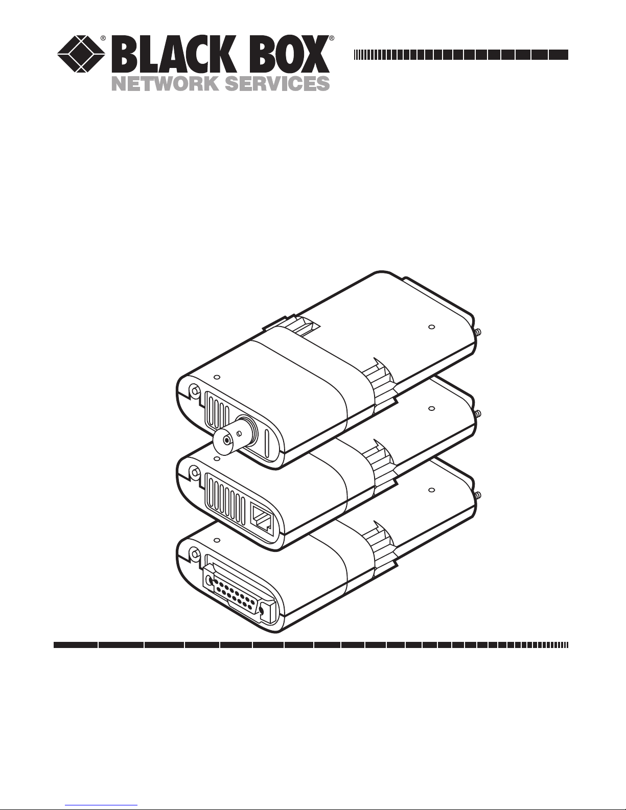
Modular Parallel Adapters
and Modular Media Units
Page 3

1
FCC/IC RFI STATEMENTS
FEDERAL COMMUNICATIONS COMMISSION AND INDUSTRY
CANADA RADIO-FREQUENCY INTERFERENCE STATEMENTS
This equipment generates, uses, and can radiate radio-frequency energy,
and if not installed and used properly, that is, in strict accordance with the
manufacturer’s instructions, may cause interference to radio communication.
It has been tested and found to comply with the limits for a Class A computing
device in accordance with the specifications in Subpart J of Part 15 of FCC rules,
which are designed to provide reasonable protection against such interference
when the equipment is operated in a commercial environment. Operation of
this equipment in a residential area is likely to cause interference, in which case
the user at his own expense will be required to take whatever measures may be
necessary to correct the interference.
Changes or modifications not expressly approved by the party responsible
for compliance could void the user’s authority to operate the equipment.
This digital apparatus does not exceed the Class A limits for radio noise emission from
digital apparatus set out in the Radio Interference Regulation of Industry Canada.
Le présent appareil numérique n’émet pas de bruits radioélectriques dépassant les limites
applicables aux appareils numériques de la classe A prescrites dans le Règlement sur le
brouillage radioélectrique publié par Industrie Canada.
TRADEMARKS USED IN THIS MANUAL
BLACK BOX and the logo are registered trademarks of Black Box Corporation.
IBM and PS/2 are registered trademarks of International Business Machines Corporation.
Microsoft, Windows, Windows NT, and LAN Manager are registered trademarks or
trademarks of Microsoft Corporation in the United States and/or other countries.
Any other trademarks mentioned in this manual are acknowledged to be the property
of the trademark owners.
Page 4

2
MODULAR PARALLEL ADAPTERS AND MODULAR MEDIA UNITS
EUROPEAN UNION DECLARATION OF CONFORMITY
This equipment complies with the requirements of the European EMC Directive
89/336/EEC with respect to the EN55022 and EN50082-1 standards.
Page 5

3
NOM STATEMENT
NORMAS OFICIALES MEXICANAS (NOM)
ELECTRICAL SAFETY STATEMENT
INSTRUCCIONES DE SEGURIDAD
1. Todas las instrucciones de seguridad y operación deberán ser leídas
antes de que el aparato eléctrico sea operado.
2. Las instrucciones de seguridad y operación deberán ser guardadas
para referencia futura.
3. Todas las advertencias en el aparato eléctrico y en sus instrucciones
de operación deben ser respetadas.
4. Todas las instrucciones de operación y uso deben ser seguidas.
5. El aparato eléctrico no deberá ser usado cerca del agua—por ejemplo,
cerca de la tina de baño, lavabo, sótano mojado o cerca de una alberca,
etc..
6. El aparato eléctrico debe ser usado únicamente con carritos o pedestales
que sean recomendados por el fabricante.
7. El aparato eléctrico debe ser montado a la pared o al techo sólo
como sea recomendado por el fabricante.
8. Servicio—El usuario no debe intentar dar servicio al equipo eléctrico
más allá a lo descrito en las instrucciones de operación. Todo otro
servicio deberá ser referido a personal de servicio calificado.
9. El aparato eléctrico debe ser situado de tal manera que su posición no
interfiera su uso. La colocación del aparato eléctrico sobre una cama,
sofá, alfombra o superficie similar puede bloquea la ventilación, no se
debe colocar en libreros o gabinetes que impidan el flujo de aire por los
orificios de ventilación.
Page 6

10. El equipo eléctrico deber ser situado fuera del alcance de fuentes
de calor como radiadores, registros de calor, estufas u otros aparatos
(incluyendo amplificadores) que producen calor.
11. El aparato eléctrico deberá ser connectado a una fuente de poder sólo del
tipo descrito en el instructivo de operación, o como se indique en el aparato.
12. Precaución debe ser tomada de tal manera que la tierra fisica y la
polarización del equipo no sea eliminada.
13. Los cables de la fuente de poder deben ser guiados de tal manera que
no sean pisados ni pellizcados por objetos colocados sobre o contra ellos,
poniendo particular atención a los contactos y receptáculos donde salen
del aparato.
14. El equipo eléctrico debe ser limpiado únicamente de acuerdo
a las recomendaciones del fabricante.
15. En caso de existir, una antena externa deberá ser localizada lejos
de las lineas de energia.
16. El cable de corriente deberá ser desconectado del cuando el equipo
no sea usado por un largo periodo de tiempo.
17. Cuidado debe ser tomado de tal manera que objectos liquidos no
sean derramados sobre la cubierta u orificios de ventilación.
18. Servicio por personal calificado deberá ser provisto cuando:
A: El cable de poder o el contacto ha sido dañado; u
B: Objectos han caído o líquido ha sido derramado dentro
del aparato; o
C: El aparato ha sido expuesto a la lluvia; o
D: El aparato parece no operar normalmente o muestra un cambio
en su desempeño; o
E: El aparato ha sido tirado o su cubierta ha sido dañada.
4
MODULAR PARALLEL ADAPTERS AND MODULAR MEDIA UNITS
Page 7

5
TABLE OF CONTENTS
Contents
Chapter Page
1. Specifications .......................................................... 8
2. Introduction .......................................................... 10
2.1 Available Models .......................................... 11
2.2 Features ........................................................ 12
3. Installation ............................................................ 14
3.1 Attaching the Modular Media Unit ............ 14
3.2 Connecting the Network Cable .................. 16
3.3 Plugging the Adapter into the Computer .... 19
3.4 Powering the Adapter ................................ 20
3.4.1 Using the Interface-Power Cable ........ 20
3.4.2 Using an External AC Power Supply
(Optional) .............................................. 22
4. Software Setup and Operation ............................ 23
4.1 Supplied Files .............................................. 23
4.2 Installing and Configuring
the NDIS 3 Driver for
Microsoft Windows or Windows NT .......... 26
4.2.1 Installing the Driver in Windows 95 ........27
Page 8

Contents (continued)
Chapter Page
4.2.2 Installing the Driver in Windows
for Workgroups .................................... 28
4.2.3 Installing the Driver in Windows NT ......29
4.2.4 Configuring the Driver (Optional)..........30
4.3 Installing and Configuring the NDIS
Driver for Microsoft LAN Manager ............ 31
4.3.1 Installing the Driver for LAN Manager
Version 2.1 and Later .......................... 31
4.3.2 Installing the Driver for LAN
Manager Version 2.0 .............................. 32
4.3.3 Configuring the Driver (Optional) ...... 33
4.4 Using the ODI Driver for Novell NetWare .... 34
4.4.1 Installing the Driver .............................. 34
4.4.2 Configuring the Driver (Optional) ...... 34
4.4.3 Operating the Driver ............................ 36
4.5 Using the LANtastic/AI Version 5.x Driver .. 37
4.5.1 Installing the Driver .............................. 37
4.5.2 Configuring the Driver (Optional) ...... 38
4.5.3 Operating the Driver ............................ 38
4.6 Installing and Configuring the Packet Driver .. 39
4.6.1 Installing the Driver .............................. 39
4.6.2 Configuring the Driver (Optional) ...... 40
5. Driver Options ..........................................................41
6
MODULAR PARALLEL ADAPTERS AND MODULAR MEDIA UNITS
Page 9

7
TABLE OF CONTENTS
Contents (continued)
Chapter Page
6. Self-Testing and Diagnostics ................................ 43
6.1 Running the Diagnostics Program ............ 43
6.2 Menu Options .............................................. 45
6.2.1 Advanced RAM Test .............................. 45
6.2.2 LPT Report ............................................ 46
6.2.3 View Configuration Files ...................... 46
6.2.4 Help ...................................................... 46
6.2.5 Quit ........................................................ 46
7. Error Messages .................................................. 47
8. Troubleshooting ................................................ 49
8.1 Calling Black Box ........................................ 50
8.2 Shipping and Packaging .............................. 51
Page 10

1. Specifications
Compliance — CE, FCC Part 15 Subpart J Class A,
IC Class/classe A
Standard — IEEE 802.3 Ethernet v.2
Data Rate — 10 Mbps
Memory — (8) 32-KB network buffer segments
Interfaces and
Connectors — All Modular Parallel Adapters: IBM
PC parallel (DB25 male);
LE073A-R2, LE171: 10BASE-T (RJ-45 female);
LE074A-R2, LE172: 10BASE2 (ThinNet, BNC female);
LE076A: Either 10BASE-T (RJ-45 female) or
10BASE2 (ThinNet, BNC female), user-selectable;
LE075A-R2, LE175: 10BASE5 AUI (DB15 female)
Temperature
Tolerance — Operating: 32 to 122˚F (0 to 50˚C);
Storage: 32 to 158˚F (0 to 70˚C)
8
MODULAR PARALLEL ADAPTERS AND MODULAR MEDIA UNITS
Page 11

9
CHAPTER 1: Specifications
Power — 5 VDC at up to 500 mA from PC’s
keyboard or mouse port through interface-power
cable;Can also be used with any standard AC
power supply that outputs between 4 and 20 VDC
at 500 mA on a center-positive barrel plug
Size — Adapter with Media Unit installed:
1"H x 2.4"W x 4.1"D (2.5 x 6.1 x 10.4 cm)
Weight — Adapter with Media Unit installed: 3 oz. (85 g)
Page 12

10
MODULAR PARALLEL ADAPTERS AND MODULAR MEDIA UNITS
2. Introduction
The Modular Parallel Adapter easily connects notebook,
laptop, and desktop PCs to virtually any Ethernet Local
Area Network. It connects externally to a standard
parallel printer port, eliminating the need to install
internal Ethernet cards.
The Adapter is easy to install; there are no jumpers or
configuration switches to set. The device is the perfect
solution for notebook and laptop connectivity, as well as
for workstations with a limited number of internal
expansion slots.
The Adapter comes with one of several types of
Modular Media Units preattached to its network end.
Each Unit is designed for a different Ethernet interface
or set of interfaces. This allows the Adapter to be the
connection point for several common Ethernet cable
types. And because the Modular Media Units are
interchangeable, you can substitute one Unit for
another to connect the Adapter to any of these cable
types as necessary.
Page 13

11
CHAPTER 2: Introduction
2.1 Available Models
The Modular Parallel Adapters’ preinstalled Modular
Media Units have different connectors to natively
support different Ethernet interfaces and cable types:
• LE073A-R2 has an RJ-45 jack to support 10BASE-T
on unshielded twisted pair.
• LE074A-R2 has a female BNC connector to support
10BASE2 ThinNet on RG58A/U coaxial cable.
• LE075A-R2 has a DB15 female connector to support
10BASE5 AUI.
Unlike the other three models, LE076A comes with
Media Units for both 10BASE-T and 10BASE2. Attach the
Unit you need.
Swap in any of the separately available Modular Media
Units to connect the Adapters to Ethernet interfaces
they don’t already support: LE171 for 10BASE-T, LE172
for ThinNet, or LE175 for AUI. The LE076A Adapter
comes with two Media Units, one for 10BASE-T and
one for 10BASE2; you can swap these Media Units as
necessary.
Page 14

12
MODULAR PARALLEL ADAPTERS AND MODULAR MEDIA UNITS
2.2 Features
The Modular Parallel Adapter has these features:
• Fits any Ethernet cable type through the use
of snap-on Modular Media Units.
•
Supplied with drivers for
Microsoft Windows®and
Windows NT
®
(NDIS 3),
Microsoft®LAN Manager
®
(NDIS),
Novell®NetWare®(ODI™), ARTISOFT
®
LANtastic®,
and Packet TCP/IP.
• Powered by the PC’s keyboard or mouse port
through an interface-power cable, or (optionally)
by any standard non-regulated power supply that
outputs between 4 and 20 VDC at 500 mA.
• Supports Enhanced Parallel Port (EPP) for
increased performance.
• Provides extensive diagnostics and self-testing.
• Automatically selects unidirectional or bidirectional
mode.
• Supports parallel ports LPT1 through LPT4.
• Supports interrupt lines IRQ7 and IRQ5, as well
as polling mode when no interrupt line is available.
Page 15
13
CHAPTER 2: Introduction
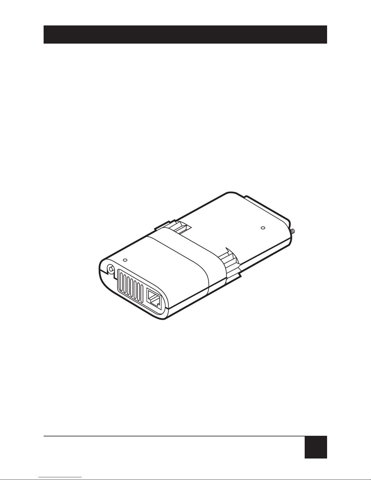
• Power and network activity LEDs.
• Fast and easy installation.
• No jumpers or switches to set.
Figure 2-1 shows a typical Adapter, including the
preinstalled Modular Media Unit.
Figure 2-1. A Modular Parallel Adapter with its preinstalled
Modular Media Unit.
Page 16

14
MODULAR PARALLEL ADAPTERS AND MODULAR MEDIA UNITS
3. Installation
Installing your Modular Parallel Adapter is a four-step
process:
1. Attach the media unit (Section 3.1).
2. Connect the network cable (Section 3.2).
3. Plug the Adapter into the computer (Section 3.3).
4. Attach the interface-power cable or AC power
supply (Section 3.4).
IMPORTANT!
Make sure the computer is turned
off while you install the Adapter.
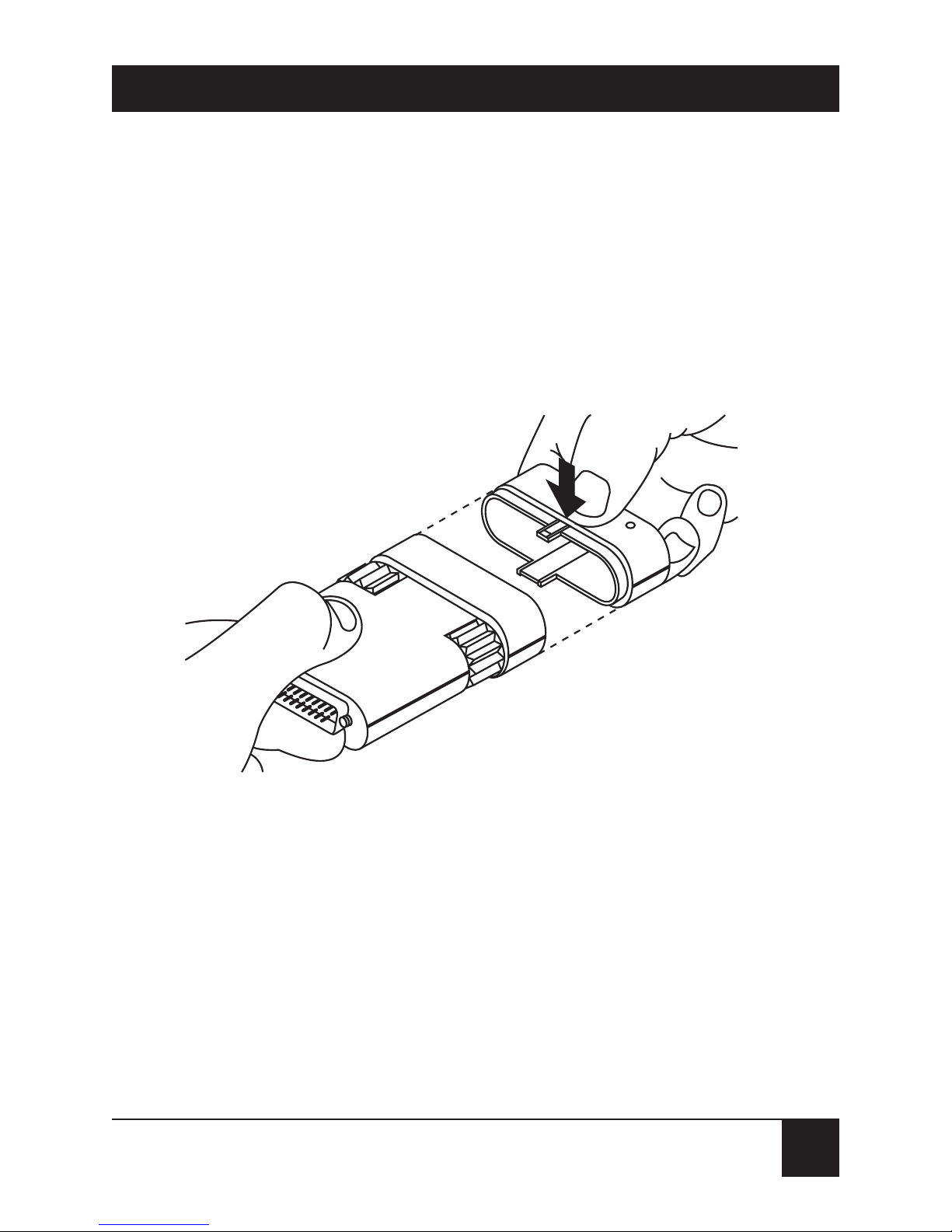
3.1 Attaching the Modular Media Unit
Your Modular Parallel Adapter might come in one piece
with a Modular Media Unit preinstalled on the end of it,
or it might come with the Adapter and Media Unit(s)
separated. If the Media Unit isn’t attached to the
Adapter when you receive it, hold the Adapter with the
logo facing up, press the top and bottom of the Media
Unit together, and press the Unit into the Adapter until
it snaps into place (see Figure 3-1).
Page 17
15
CHAPTER 3: Installation
If you’ve purchased a Modular Media Unit separately
and you want to swap it in for a Media Unit already
installed on an Adapter, remove the installed Unit by
pressing its top and bottom together and sliding it off.
Then attach the new Unit as described in the previous
paragraph.
Figure 3-1. Attaching the Media Unit.
Page 18

16
MODULAR PARALLEL ADAPTERS AND MODULAR MEDIA UNITS
3.2 Connecting the Network Cable
How you connect the network cable to the Modular
Parallel Adapter will depend on the Adapter’s Ethernet
interface:
•
LE073A-R2, LE076A with 10BASE-T Media Unit
installed: Connect the 10BASE-T cable as shown in
Figure 3-2.
Figure 3-2. Connecting a 10BASE-T cable
to a 10BASE-T Adapter or Unit.
NOTE
It’s possible to use these Adapter models with non10BASE-T UTP networks such as Starlan 10, but if you
do, you’ll need to disable link-integrity testing. Refer to
Chapter 5.
Page 19

17
CHAPTER 3: Installation
• LE074A-R2, LE076A with 10BASE2 Media Unit
installed: Make sure that your RG-58A/U coaxial
ThinNet cable has a T-connector at the end of it.
Then attach the T-connector to the BNC connector
at the back of the Media Unit as shown in
Figure 3-3.
Figure 3-3. Connecting a ThinNet cable to a ThinNet Adapter or Unit.
NOTE
Both ends of the T-connector must be attached to
network cabling. If the Adapter is at the end of a network
segment, the end of the T-connector that’s not attached
to the network must have a 50-ohm terminator installed
on it.
Page 20

18
MODULAR PARALLEL ADAPTERS AND MODULAR MEDIA UNITS
• LE075A-R2 Connect the AUI cable as shown in
Figure 3-4. After you attach the cable plug to the
Adapter, press the slide latch to the left to lock the
connector in place.
Figure 3-4. Connecting an AUI cable to an AUI Adapter or Unit.
Page 21

19
CHAPTER 3: Installation
3.3 Plugging the Adapter into the Computer
Plug the DB25 connector on your Modular Parallel
Adapter into the parallel port on the back of your
notebook or laptop computer, holding the Adapter with
the logo at the top. Tighten the knobs on the Adapter
clockwise to fasten it tightly, as shown in Figure 3-5.
Figure 3-5. Plugging the Adapter into the computer.
PC’s parallel port
(DB25 female)
Page 22

20
MODULAR PARALLEL ADAPTERS AND MODULAR MEDIA UNITS
3.4 Powering the Adapter
3.4.1 U
SING THEINTERFACE
-P
OWERCABLE
Making sure that the computer is turned off first, plug
the included interface-power cable’s DC plug into the
small round socket in the back of the Modular Parallel
Adapter. Plug the other end of the cable into the 6-pin
mini-DIN PS/2
®
style keyboard/mouse port on the
computer, as shown in Figure 3-6. Now turn on the
computer. The Adapter’s red Power LED should light
up.
Note that the interface-power cable has a pass-through
port on its computer end. This will let you plug a
keyboard or mouse into the computer even though the
power cable is already plugged into that port.
CAUTION!
Do not use power-management or power-saver features
on your computer when you’re using the interfacepower cable. If you do, the computer might reduce
power output on its PS/2 port to levels so low that the
Adapter won’t be able to operate.
Page 23

21
CHAPTER 3: Installation
Figure 3-6. Attaching the interface-power cable to the Adapter.
Page 24

22
MODULAR PARALLEL ADAPTERS AND MODULAR MEDIA UNITS
3.4.2 U
SING ANEXTERNAL
AC P
OWERSUPPLY
(O
PTIONAL
)
If you’d rather, you can use an AC power supply with the
Modular Parallel Adapter. The Adapter doesn’t come
with a power supply, but is compatible with standard
non-regulated power supplies that output 4 to 20 VDC at
500 mA on a center-positive barrel plug.
To install such a power supply, plug its output cable
into the small round socket on the back of the Modular
Parallel Adapter, as shown in Figure 3-7. Plug the power
supply’s transformer (if it’s a wallmount type) or its
input cord (if it’s an inline type) into any standard
electrical outlet. The Adapter’s red Power LED should
then light up.
Figure 3-7. Attaching an AC power supply to the Adapter
(wallmount 115-VAC supply shown).
Power LED
Activity LED
Page 25

23
CHAPTER 4: Software Setup and Operation
4. Software Setup and Operation
The Modular Parallel Adapter is supplied with software
driver programs that support all major network
operating systems (NOSes). These drivers are found on
the “Network Drivers” diskette. This chapter describes
the use of each major NOS driver. Instructions on how
to use the other drivers are included in the
README.DOC file on the Network Drivers diskette.
4.1 Supplied Files
The included Network Drivers diskette contains the
following files:
• README.DOC—Update information about the
software
• SETDIAG.EXE—Self-test and diagnostic program
• SETDIAG.HLP—Help file for the diagnostic
program
• OEMSETUP.INF—Configuration file for Windows
for Workgroups
• SETNDIS.DOS—DOS NDIS driver for Windows
for Workgroups
Page 26

24
MODULAR PARALLEL ADAPTERS AND MODULAR MEDIA UNITS
The \NDIS subdirectory contains NDIS files for use with
Microsoft Windows, Microsoft LAN Manager, 3Com
®
3+Open®, Banyan®VINES™, DEC™ Pathworks™,
Wollongong
®
TCP/IP, and other network operating
systems that use the NDIS interface specifications:
• PROTOCOL.INI—Sample protocol initialization file
• SETDOS.NIF—Configuration file used by Microsoft
LAN Manager’s setup program for configuring a
DOS workstation
• SETNDIS.DOS—NDIS driver for DOS
• SETNDIS.OS2—NDIS driver for OS/2
®
• SETOS2.NIF—Configuration file used by Microsoft
LAN Manager’s setup program for configuring an
OS/2 workstation
The \MSLANMAN.DOS\DRIVERS subdirectory
contains the driver and files for Microsoft LAN Manager
DOS workstation.
• .\ETHERNET\POCKET\PROTOCOL.INI—
Sample initialization file
• .\ETHERNET\POCKET\SETNDIS.DOS—Driver
for Microsoft LAN Manager DOS workstation
• .\NIF\SETDOS.NIF—Configuration file used
by the setup program
Page 27

25
CHAPTER 4: Software Setup and Operation
The \MSLANMAN.OS2\DRIVERS subdirectory contains
the drivers and files for Microsoft LAN Manager OS/2
workstation.
• .\ETHERNET\POCKET\PROTOCOL.INI—
Sample initialization file
• .\ETHERNET\POCKET\SETNDIS.OS2—Driver
for Microsoft LAN Manager OS/2 workstation
• .\NIF\SETOS2.NIF—Configuration file used by
the setup program
The \ODI subdirectory contains these DOS ODI files
for use with Novell NetWare and other network
operating systems that use the ODI specifications:
• LSL.COM—The Novell Link Support Layer
program
• IPXODI.COM—The Novell IPX™ program
• NETX.EXE—NetWare shell for use with DOS
• STARTNET.BAT—A batch file containing
all commands required to load the driver
• NET.CFG—Sample protocol configuration file
• SETODI.INS—Driver information file
• SETODI.COM—DOS ODI driver for NetWare
Page 28

26
MODULAR PARALLEL ADAPTERS AND MODULAR MEDIA UNITS
The \LANTASTI subdirectory contains the driver
for ARTISOFT
®
LANtastic/AI v.5x.
• SETLAN.COM—Driver for LANtastic/AI
• SETLAN.DOC—Document that explains how
to use the driver with LANtastic
The \PACKET subdirectory contains a Packet
driver for uses such as TCP/IP applications.
• SETPACKET.COM—Packet driver
4.2 Installing and Configuring the NDIS 3 Driver for Microsoft
Windows or Windows NT
The Modular Parallel Adapter comes with an NDIS 3
driver that works with various versions of Microsoft
Windows and Windows NT:
• To install the driver in Windows 95, see Section
4.2.1.
• To install the driver in Windows for Workgroups
3.1.1, see Section 4.2.2.
• To install the driver in Windows NT 3.x or 4.0,
see Section 4.2.3.
• To configure the driver in any of these operating
systems, see Section 4.2.4.
Page 29

27
CHAPTER 4: Software Setup and Operation
NOTE
This driver does not work with Windows 98, Windows
2000, or Windows Me. We do not recommend
attempting to use the Modular Parallel Adapter with PCs
running any of these operating systems.
4.2.1 I
NSTALLING THEDRIVER INWINDOWS
95
To install the Modular Parallel Adapter’s NDIS 3 driver
for Microsoft Windows 95, take these steps:
1. Select the “Network” option from the Windows
Control Panel.
2. Select “Add.”
3. Select “Adapter,” then click “Add.”
4. Click on “Have disk.”
5. Insert the Network Drivers diskette in your floppy
drive.
6. Type “WIN95” at the “A:\” prompt in the “Add
adapter” window, then click on “OK.”
Windows will update and copy the appropriate files
to your hard drive. To run this new driver, you’ll have
to reboot your PC.
Page 30

28
MODULAR PARALLEL ADAPTERS AND MODULAR MEDIA UNITS
4.2.2 I
NSTALLING THEDRIVER INWINDOWS FORWORKGROUPS
To install the Modular Parallel Adapter’s NDIS 3 driver
for Microsoft Windows for Workgroups 3.1.1, take these
steps:
1. Start Windows by typing “WIN” at the DOS prompt.
2. Select the “Network” group.
3. Click on “Network Setup,” then on “Drivers.”
4. Click on “Add Adapter” followed by “OK.”
5. Insert the Network Drivers diskette in your floppy
drive.
6. Type “WFW311” at the “A:\” prompt in the “Add
adapter” window, then click on “OK.”
7. Select the NDIS 3 driver, then click on “OK.”
8. Click on “Close” followed by “OK.”
Windows will update and copy the appropriate files
to your hard drive. To run this new driver, you’ll have
to reboot your PC.
Page 31

29
CHAPTER 4: Software Setup and Operation
4.2.3 I
NSTALLING THEDRIVER INWINDOWS
NT
To install the Modular Parallel Adapter’s NDIS 3 driver
for Microsoft Windows NT version 3.x or 4.0, take these
steps:
1. Start Windows NT.
2. Click on the “Main” program group.
3. Select “Network.”
4. Choose “Add adapter.”
5. Insert the Network Drivers diskette in your floppy
drive.
6. At the “A:\” prompt in the “Add adapter” window,
type “WINNT31” if you are running Windows NT
3.1, “WINNT35” if you are running Windows NT
3.5, or “WINNT40” if you are running Windows NT
4.0. Click on “OK.”
7. Select the “Ethernet Adapter,” then press “OK.”
8. Click on “Finish.”
Windows NT will update and copy the appropriate files
to your hard drive. To run this new driver, you’ll have
to reboot your PC.
Page 32

30
MODULAR PARALLEL ADAPTERS AND MODULAR MEDIA UNITS
4.2.4 C
ONFIGURING THEDRIVER
(O
PTIONAL
)
SETNDIS, the NDIS 3 driver for all versions of Windows,
is a self-configuring driver that automatically detects the
correct LPT port, interrupt line, and unidirectional/
bidirectional mode to be used. If you have a special
configuration, you may need to override this automatic
selection by editing the driver’s PROTOCOL.INI file.
The Adapter’s section in PROTOCOL.INI includes:
;MODULAR PARALLEL ADAPTER DRIVERNAME =
SETNDIS$
;POLLING
;UNIDIR
;LPTn
;EPP
;FRAME ETHERNET_802.2
;DISABLELINK
Lines preceded by semicolons are comments;
“commented” options are deactivated. To manually set
an option, edit the semicolon out of the corresponding
line. For explanations of these options, refer to
Chapter 5.
Page 33

31
CHAPTER 4: Software Setup and Operation
NOTE
After changing the configuration of this driver on some
Compaq
®
Presario®computers running Windows 95,
you might need to shut down the computer and bring it
back up to make the changes effective.
4.3 Installing and Configuring the NDIS Driver for Microsoft LAN
Manager
This section describes how to install and configure the
Modular Parallel Adapter’s NDIS driver for Microsoft
LAN Manager for DOS and OS/2.
NOTE
If you’re using an NDIS-compatible network operating
system other than LAN Manager (3Com 3+Open,
Banyan VINES, DEC Pathworks, Wollongong TCP/IP
and NFS, etc.), follow the manufacturer’s operatingsystem instructions for loading new drivers. The driver
files are located in the \NDIS subdirectory on the
Network Drivers diskette.
4.3.1 I
NSTALLING THEDRIVER FOR
LAN M
ANAGERVERSION
2.1
ANDLATER
To install the driver for version 2.1 and later versions
of LAN Manager:
1. Begin installation of LAN Manager using “setup.”
Page 34

32
MODULAR PARALLEL ADAPTERS AND MODULAR MEDIA UNITS
2. When prompted to select the available networkadapter driver, choose “Other Driver.”
3. When prompted, insert the Network Drivers diskette.
4. Select “Modular Parallel Adapter” from the menu.
5. Continue with the installation until it is completed.
6. Reboot the PC.
4.3.2 I
NSTALLING THEDRIVER FOR
LAN M
ANAGERVERSION
2.0
To install the driver for version 2.0 of LAN Manager:
1. Begin installation of LAN Manager using “setup.” At
the “Import Network Drivers” screen, choose “YES.”
2. Insert the Network Drivers diskette.
3. Select “Modular Parallel Adapter” from the list
of drivers to import.
4. At the Network Drivers menu, select “Modular
Parallel Adapter” from the list of drivers to install.
5. Continue with the installation until it is completed.
6. Reboot the PC.
Page 35

33
CHAPTER 4: Software Setup and Operation
4.3.3 C
ONFIGURING THEDRIVER
(O
PTIONAL
)
SETNDIS is a self-configuring driver that automatically
detects the correct LPT port, interrupt line, and
unidirectional/bidirectional mode to be used. If you
have a special configuration, you may need to override
this automatic selection by editing the PROTOCOL.INI
file in the C:\LANMAN\DRIVERS\MODADPT directory.
PROTOCOL.INI consists of these lines:
;MODADPT ADAPTER
DRIVERNAME=SETNDS$
;LPTn
;UNIDIR
;POLLING
;EPP
;DISABLELINK
The keyword “POLLING” is not available with
the OS/2 driver. Lines preceded by semicolons are
comments. To select an option, edit the semicolon
out of the corresponding line. The
“DRIVERNAME=SETNDS$” line is required by LAN
Manager. For further explanation of these options,
refer to Chapter 5.
Page 36

34
MODULAR PARALLEL ADAPTERS AND MODULAR MEDIA UNITS
4.4 Using the ODI Driver for Novell NetWare
4.4.1 I
NSTALLING THEDRIVER
The ODI driver is used with all Novell NetWare versions
and with other network software based on the IPX
protocol. All you need to do to install this driver is to
copy all the files from the \ODI subdirectory on the
Network Drivers diskette to the NetWare subdirectory
on your hard disk.
NOTE
Novell DOS ODI users should use NETX.EXE v3.32
(contained on the Network Drivers diskette) or a newer
version. Older versions of NETX.EXE do not work
properly under MS-DOS 6.0. For other NOSes, please
refer to corresponding documentation and to the file
NETWORKS.TXT, supplied with MS-DOS 6.0.
4.4.2 C
ONFIGURING THEDRIVER
(O
PTIONAL
)
The NET.CFG file is an auxiliary file used by the ODI
driver. It includes configuration information about the
network adapters in your workstation. If you do not use
any of the special options listed in this section, you do
not need to edit NET.CFG.
The sample NET.CFG file supplied in the \ODI
subdirectory includes the following commands:
Page 37

35
CHAPTER 4: Software Setup and Operation
LINK DRIVER SETODI
;FRAME ETHERNET_802.2
;POLLING
;UNIDIR
;LPTn
;EPP
;DISABLELINK
Lines preceded by semicolons are comments;
“commented” options are deactivated. To select an
option, edit the semicolon out of the corresponding
line. For explanations of these options, refer to
Chapter 5.
The Adapter driver section in the NET.CFG file
must start with the line LINK DRIVER SETODI, which
identifies the driver to which the selected options apply.
The next line is optional and must start with an empty
space, such as a true space or a tab.
Page 38

36
MODULAR PARALLEL ADAPTERS AND MODULAR MEDIA UNITS
4.4.3 O
PERATING THEDRIVER
To start work on the NetWare workstation, run the
STARTNET.BAT batch file. Then log into the network.
STARTNET.BAT includes the following set of commands:
LSL
SETODI
IPXODI ;add parameter "A" to reduce
memory usage
NETX
F:
If you wish, you may enter these commands in the
AUTOEXEC.BAT file in the order shown.
To unload the ODI workstation software, unload
the programs in reverse order using the U switch:
NETX u
IPXODI u
SETODI u
LSL u
Page 39

37
CHAPTER 4: Software Setup and Operation
4.5 Using the LANtastic/AI Version 5.x Driver
4.5.1 I
NSTALLING THEDRIVER
To install the driver for ARTISOFT LANtastic/AI v5.x:
1. Run the LANtastic/AI v5.x INSTALL program.
2. Complete the installation by entering default
parameters for the LAN adapter, then exit the
INSTALL program.
3. Copy the driver from the Network Drivers diskette
to the LANtastic subdirectory (default is
C:\LANTASTI):
copy a:\lantasti\*.* c:\lantasti
4. Edit the file STARTNET.BAT in C:\LANTASTI.
Delete the line that starts with “3C503MM” and
insert this new line:
SETLAN verbose
Page 40

38
MODULAR PARALLEL ADAPTERS AND MODULAR MEDIA UNITS
4.5.2 C
ONFIGURING THEDRIVER
(O
PTIONAL
)
SETLAN accepts the standard command-line switches
“HELP,” “XEROX,” “IEEE,” “MPX,” “PACKET_SIZE,”
“REMOVE,” “VERBOSE,” “?,” and “@.” It also accepts
the Adapter-specific switches “UNIDIR,” “LPTn,” “EPP,”
and “DISABLELINK.” For further explanation of these
special options, refer to Chapter 5.
4.5.3 O
PERATING THE
D
RIVER
To connect the Adapter’s PC to your LANtastic network,
use the batch file STARTNET.BAT that the LANtastic
installation program built for you, or use the following
commands (with appropriate options—see your
LANtastic user’s guide):
SHARE
SETLAN [parameter 1] [parameter 2]
AILANBIO
REDIR name
To use the PC as a server, enter the following additional
command:
SERVER
Page 41

39
CHAPTER 4: Software Setup and Operation
4.6 Installing and Configuring the Packet Driver
The Packet driver is based on and conforms to the FTP
Software public-domain specifications. This driver can
be used with many NOSes based on these specifications,
including FTP Software PC/TCP, Wollongong Pathway,
NSCA Telnet, and Intel Netsight.
4.6.1 I
NSTALLING THEDRIVER
Refer to your NOS documentation for instructions on
how to install the Packet driver SETPACKET.COM. This
driver can be operated from the DOS prompt or
included in a batch file. In either case, the Packet driver
should be loaded before the NOS files are activated.
Page 42

40
MODULAR PARALLEL ADAPTERS AND MODULAR MEDIA UNITS
4.6.2 C
ONFIGURING THEDRIVER
(O
PTIONAL
)
SETPACKET accepts the following software-related
command-line switches:
I xx Software interrupt #xx, where xx ranges between
60 and 80 hex. The default interrupt is 60 hex.
?,H Displays a summary of the command line
options.
Hardware-related switches are UNIDIR, EPP,
DISABLELINK, and LPTn. For explanations of these
options, see Chapter 5.
Page 43

41
CHAPTER 5: Driver Options
5. Driver Options
The configuration files for the Modular Parallel
Adapter’s drivers allow you enable, disable, and set
values for the following options:
• POLLING—A PC may use either IRQ7 or IRQ5 for
handling parallel-port communications. If you need
to work without interrupts (usually only with test
evaluations), delete the semicolon in this line. This
will force the driver to operate in a polled mode
without using hardware interrupts.
• UNIDIR—Whenever the SETODI driver is loaded into
memory, it tests the parallel port to determine whether
it can be operated in the faster bidirectional mode.
The Adapter is then configured according to the test
results. However, when you use a long extension cable
or a low-quality parallel port, the bidirectional mode
may not operate reliably, even if the test passes. In this
case, you should force the unidirectional mode by
deleting the semicolon in this line.
• LPTn—The ODI driver for the Adapter is normally
auto-configuring, automatically detecting the
correct port to be used. But to specify the exact
parallel port that the SETODI driver should work
Page 44

42
MODULAR PARALLEL ADAPTERS AND MODULAR MEDIA UNITS
with, delete the semicolon in this line and specify
the port number n from 1 to 4.
• EPP—The adapter supports the Enhanced Parallel
Port (EPP). Most PCs based on modern Intel
compatible chipsets may be configured to work
in the EPP mode. This mode improves the
performance of the adapter and therefore
is recommended if the PC supports it.
IMPORTANT!
Make sure that your PC has EPP capability before
selecting this mode.
• FRAME—The ODI driver supports multiple frame
types. Certain NOSes, such as NetWare versions
1.x through 3.11, use frame ETHERNET_802.3,
while others use ETHERNET_802.2 as default
frame type. The SETODI default frame type is
ETHERNET_802.3.
• DISABLELINK—It’s possible to use a 10BASE-T
Adapter or Modular Media Unit with some non10BASE-T unshielded twisted-pair networks such
as Starlan 10. If you do so, however, link-integrity
testing should be disabled. Unless you uncomment
“DISABLELINK,” the driver defaults to link integrity
ENABLED.
Page 45

43
CHAPTER 6: Self-Testing and Diagnostics
6. Self-Testing and Diagnostics
The Network Drivers diskette contains the SETDIAG
self-test diagnostic utility program, which tests the
Modular Parallel Adapter and reports the results of the
tests.
CAUTION!
Make sure that the network driver isn’t loaded before
you run the program. If it is, either the PC will lock up or
the software will not be able to find the Adapter.
6.1 Running the Diagnostics Program
To run the self-test and diagnostics program:
1. Copy the SETDIAG.* files from the supplied
Network Drivers diskette into the network
directory.
2. At the network directory prompt, type the
following command:
setdiag
Page 46

44
MODULAR PARALLEL ADAPTERS AND MODULAR MEDIA UNITS
The “setdiag” command may be entered with these
special command-line parameters:
e—enable EPP mode
u—force unidirectional mode
c—force colors (default is monochrome) when
color display is available
?—display a Help screen
3. The SETDIAG main menu will be displayed. This
menu includes a list of topics. To select a topic, use
the up- and down-arrow keys to highlight your
choice, then press the Enter key.
The diagnostics program verifies that the adapter has
been properly connected, executes several self-test
routines, and displays the following information:
• LPT port number and address
• IRQ line used (if any)
• Interrupt-line polarity of the parallel port
• Data-transfer method (unidirectional, bidirectional,
or other)
• Node address
• Model name and hardware version
Page 47

45
CHAPTER 6: Self-Testing and Diagnostics
• Date of manufacture
• Serial number
If the Adapter is not properly connected or not
powered, the following message is displayed:
Adapter not connected, not powered or
driver already loaded.
This message will also be displayed if one of the
Adapter drivers is loaded. In this case, unload the driver
or reboot the PC.
6.2 Menu Options
6.2.1 A
DVANCED
RAM T
EST
The diagnostics portion of the SETDIAG program
activates a brief RAM test. However, to thoroughly test
the Adapter’s RAM, several other time-consuming tests
are required. The “Advanced RAM Test” option in the
SETDIAG main menu activates these tests.
Once activated, all tests are run in a loop. The display
indicates the last run results of each test, the total
number of tests performed, and the number of test
failures, if any. The tests can be terminated at any time
by pressing any key.
Page 48

46
MODULAR PARALLEL ADAPTERS AND MODULAR MEDIA UNITS
6.2.2 LPT R
EPORT
This option in the SETDIAG main menu displays all of
the PC’s available parallel ports and indicates which one
the Adapter is connected to.
6.2.3 V
IEWCONFIGURATIONFILES
This option allows the user to view the contents of the
different configuration files (NET.CFG for Novell ODI
and PROTOCOL.INI for LAN Manager NDIS). If the
file is longer than the window on the screen, use the up
and down arrow keys to scroll through the file.
To modify the configuration files, use your preferred
text editor.
6.2.4 H
ELP
This option provides a detailed description of all self-test
and diagnostics options.
6.2.5 Q
UIT
Select this option to exit from the SETDIAG program.
Page 49

47
CHAPTER 7: Error Messages
7. Error Messages
If your Modular Parallel Adapter has an internal
problem or failure while it’s operating, one of the
messages listed in this chapter might pop up on your
PC’s screen. Error messages can be recognized by the
beep and the word “FATAL” that precedes them. All
other messages that the Adapter displays on the screen
are for information only.
Modadpt Ethernet Adapter is not connected or not
powered.
Check that the Adapter is connected to the AC power
supply and that the Adapter’s red Power LED is on.
Check that the Adapter is properly plugged
into a parallel (printer) port on the computer.
Page 50

48
MODULAR PARALLEL ADAPTERS AND MODULAR MEDIA UNITS
Run the SETDIAG diagnostic program to
get more information about the problem.
Adapter failed to initialize correctly.
The adapter-initialization process failed. This message
is usually accompanied by another message that provides
more information about the reasons for the failure.
Modadpt Ethernet Adapter Memory (RAM) failure.
The adapter failed during a memory test.
Try to load the driver with the parameter UNIDIR.
Run the SETDIAG diagnostic program before
requesting service.
Modadpt Ethernet Adapter EEPROM read failure.
The adapter failed to read the EEPROM information
correctly.
In most cases, this warning will not prevent the driver
from loading.
Run the SETDIAG diagnostic program before
requesting service.
Additional error messages related to your network
operating system are described in the appropriate NOS
manuals.
Page 51

49
CHAPTER 8: Troubleshooting
8. Troubleshooting
While we trust that your Modular Parallel Adapter will
operate reliably over a long period of time, problems
might occur as they would with any complex piece of
equipment. If they do, take these steps, then contact
Black Box:
1. Make sure that your Adapter is properly installed,
powered, and connected to the network.
2. Run SETDIAG and write down the results of the
diagnostics.
3. Try to operate your adapter in unidirectional and
polling modes, by inserting the appropriate lines in
your NET.CFG or PROTOCOL.INI files (see
Chapter 5).
4. Write down any error messages that have been
displayed.
Page 52

50
MODULAR PARALLEL ADAPTERS AND MODULAR MEDIA UNITS
8.1 Calling Black Box
If you determine that your Modular Parallel Adapter is
malfunctioning, do not attempt to alter or repair it. It
contains no user-serviceable parts. Contact Black Box
Technical Support at 724-746-5500.
Before you do, make a record of the history of the
problem. We will be able to provide more efficient and
accurate assistance if you have a complete description,
including:
• the nature and duration of the problem;
• when the problem occurs;
• any error messages that have been displayed;
• the components involved in the problem—that is,
what type of computer, what type of network cabling
and software, etc.;
• any particular application that, when used, appears
to create the problem or make it worse; and
• the results of running SETDIAG and of any other
tests you’ve already done.
Page 53

51
CHAPTER 8: Troubleshooting
8.2 Shipping and Packaging
If you need to transport or ship your Modular Parallel
Adapter:
• Package it carefully. We recommend that you use
the original container.
• If you are shipping the unit for repair, please
include all parts of its external power supply. If you
are returning the unit, please include everything
you received with it. Before you ship it back to Black
Box for repair or return, contact us to get a Return
Authorization(RA)number.
Page 54

52
NOTES
 Loading...