

Page 1
RD-2TD-2RD-1TD-1PWR
PWR
RTS
TD RD DCD
Cable Required: Between ME760A units: Unloaded twisted pair, 19 to 26
gauge; 4-wires for full duplex, at least 2 wires for half-duplex; DC
continuity not required;
Between ME760A unit and DTE: EIA RS-232 cable with DB25
male connector on ME760A end.
Interface: Serial EIA RS-232D/CCITT V.24, DCE; RTS/CTS delay 0,8 or
64 ms (user-selectable).
Protocol: Synchronous or Asynchronous
Clock Source: Either internal, external from local DTE, or recovered from
remote DTE.
Data Format: 5, 6, 7 or 8 data bits; 1, 1.5, or 2 stop bits; even, odd,
or no parity.
Operation: 2- or 4-wire half-duplex or 4-wire full-duplex; point-to-point or
multipoint.
Data Rate: Sync: 1.2, 2.4, 3.6, 4.8, 7.2, 9.6, 14.4, or 19.2 Kbps;
Async: Up to 19.2 Kbps.
Modulation: Differential diphase Eurocom Standard D1
Transmit Level: 0, -3, -6, or -9 dBm (user-selectable).
Transmit Impedance: 600, 300, 150 or "LOW" ohms (user-selectable).
Receive Impedance: 150, 300, 600 or "HIGH" ohms (user-selectable).
Return Loss: Greater than 15 dB.
Carrier: Controlled by RTS or constantly ON (user-selectable).
BLACK BOX
ME760AE
TEST
LDM-MR 19.2
DIG ANA REM
XMT RCV GND
DIGANAREM
DB25 CONNECTOR
EN
DIS
ENABLE /
DISABLE
SWITCHES
2 W
4 W
2/4 WIRE
CARRIER
CTRL
ON
AGC
CTRL
ON
1 2 3 4
ON
XMT TIMING
ASY LENGTH
INT. CLK
EXT. CLK
RCV. CLK
ASYNC
CTS DELAY
0 msec
8 msec
64 msec
XMT IMPD
600
300
150
LOW
RPF
ON
OFF
PIN 18
AN. LP
EN
DIS
EN
DIS
PIN 21
(RLB)
XMT LEVEL
0 dbm
-3 dbm
-6 dbm
-9 dbm
RCV IMPD
150
300
600
HIGH
2
DATA RATE
SELECTION
PWRRTSTDRDDCDTEST
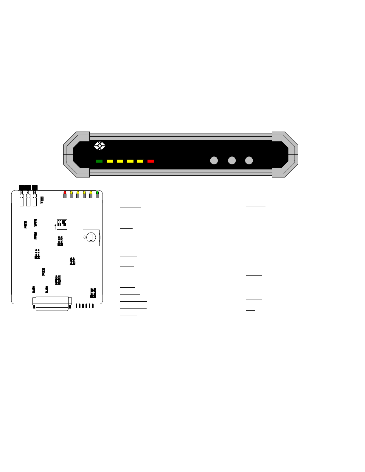
User Controls: (21) Total: (3) Front-mounted pushbuttons:
DIG (local digital loopback)
ANA (local analog loopback)
REM (remote digital loopback)
(18) Internal:
(1) Dial: Data Rate;
(5) Single-position DIP switches:
(1) Enable/Disable front-panel pushbuttons;
(1) Async character length;
(1) Not used:
(12) Jumpers:
Transmit Timing; 2- or 4-wire operation;
CTS Delay; Carrier Control; Transmit Level;
Transmit-line Impedance; Receive-line
Impedance; Enable/Disable analog-loopback
command on Pin 18; Enable/Disable remoteloopback command on Pin 21; Connect/
Disconnect signal ground and chassis ground
AGC control; Activate/Deactivate V.54 delay.
Diagnostics: Comply with V.54 standard:
Local analog loopback, mechanically or electrical user-controllable;
Local digital loopback, mechanically user-controllable;
Remote digital loopback, mechanically or electrically user-controllable.
Indicators: (6) Front-mounted LED's: PWR, RTS, TD, RD, DCD, TEST.
Connectors: (2) Rear-mounted: (1) DB25 for cable to DTE, (1) 4-wire terminal
block for modem-to-modem line.
Power: Directly from outlet through attached 5-ft. (1.5m) line cord:
ME760A: 230 VAC, 47 to 63 Hz, 3 watts.
SPECIFICATIONS:
Page 2

INTRODUCTION:
The LDM-MR19.2 is a short-range modem which operates at full- or half-duplex with synchronous or asynchronous transmission over unconditioned telephone lines. With an extended range of up to 34 miles (55 km), the LDM-MR19.2 operates at any of
eight selectable data rates, up to 19,200 bps. By using conditioned differential diphase modulation (Eurocom Std. D1), the LDM-MR19.2 provides immunity from background noise, eliminates normal line distortion, and enables efficient transmission and
reception of serial data over twisted-pair cable. The LDM-MR19.2 is coupled to the telephone line through isolation transformers. The transformers and electronic circuitry protect against AC or DC overvoltages. The protection circuitry allows operation
even when DC is connected to the line because of the following:
Transmit Level and Transmit Receive impedance's are independently selectable.
Transmit timing is provided internally, derived externally from the data terminal, or regenerated from the Receive signal.
Receive timing is regenerated from the Receive signal.
Line communication is always synchronous. when you set the modem to asynchronous mode, it performs as async-to-sync conversion in compliance with the CCITT V.22 bis standard. The LDM-MR19.2 also features V.54 diagnostic capabilities for
performing local analog loopback and local and remote digital loopback. In the digital loopback mode, the operator at either end of the line may test both of the modems and the line. The operator can control the loopback with either the front-panel
pushbuttons or Pins 18 and 21 of the V.24/RS-232 interface.
FUNCTIONAL DESCRIPTION:
ENCODER:
The encoder modulates the input data from the DTE using the "conditional diphase modulation" technique. You can configure the encoder to operate in one of five modes:
1. 4-wire full-duplex
2. 4-wire half-duplex
3. 2-wire half-duplex
4. 4-wire multipoint
5. 2-wire multipoint
MODULATION TIMING:
The modulation-timing circuit supplies the Transmit clock to the encoder. Four clock sources are available:
1. INT. CLK.= internal clock--from the modem's internal crystal oscillator.
2. EXT. CLK. = external clock--from DTE, Pin 24.
3. RCV. CLK = receive clock recovered from Receive signal.
4. ASYNC = asynchronous timing for working with the async-to-sync converter in an async application.
Setting the XMT TIMING jumpers determines the timing option.
ASYNC-TO-SYNC CONVERTER:
The LDM-MR19.2 provides internal conversion from async to sync in compliance with CCITT V.2 bis. According to this standard, frequency deviation between the modem and the DTE is compensated for by shortening or lengthening the stop bit of
the async character. When the modem's frequency is higher than the DTE's, the local converter extends the stop bit. When the modem's frequency is lower than the DTE's the local converter may delete one stop bit every four or eight characters. The
remote converter adds a shorter stop bit before sending the data to the remote DTE. For frequency deviations of up to 1.1%, the stop bits should be shortened every eight characters (12.5%). For frequency deviations of 1.2 % to 2.3%, the stop bits should
be shortened every four characters (25%). User Switch position 2 (S2) of the "ASYNC LENGTH" DIP switch to select 25% or 12.5% frequency deviation. For proper operation of the async-to-sync converter, set the async character length by adjusting
switch positions 3 and 4 (S3 and S4) of the "ASYNC LENGTH" DIP switch.
XMT LEVEL:
Four options are available for the XMT level (signal level): 0, -3, -6, or -9 dBm. XMT level is controlled by the XMT LEVEL jumper.
RECEIVER:
The receiver contains several circuits.
1. The RECEIVE FILTER removes all the out-of-band frequencies.
2. The AUTOMATIC EQUALIZER is made up of several equalizers activated according to data rate.
3. The digital AGC (automatic gain control) automatically compensates for the attenuation of the line. You may choose between the two modes of AGC operations by setting the AGC jumper:
ON: The AGC operates continuously.
CNTR: The AGC is active only when DCD is ON. When DCD is OFF, the AGC will remain in the state to which it was most recently set.
In full-duplex point-to-point applications, there is no difference between the two AGC modes of operation. However, there is a difference in multipoint applications, where the master modem communicates with modems at different distances. When the
master modem is set to AGC-ON, the master can communicate across long distances (up to its maximum range) to the slave modems. However, this setting increases the RTS-to-CTS delay. For example, under AGC-ON, the CTS delay of all slaves must
be set to 64 ms when the data rate is less than 9.6 Kbps.
When the master modem is set to AGC-CNTR, it can't transmit or receive across as much distance. However, the polling goes faster. For example, under AGC-CNTR, the CTS delay of all units can be set to 8 ms when the data rate is greater than or
equal to 4.8 Kbps.
V.54 DIAGNOSTICS:
You can activate V.54 loops with either the front-panel pushbuttons or Pins 18 and 21 can be enabled or disabled separately by the SWITCH, PIN 18 and PIN 21 jumpers, respectively. When you use the LDM-MR19.2 as a tail end to a DDS
network, set the V.54 DELAYjumpers of the modems located close to the DDS network to ON to prevent multiple loopbacks. The DELAY switch prevents the last modem from receiving the complete V.54 data sequence and being induced into a
loop. V.54 is required only for operation in synchronous mode.
NOTE:
The V.54 DELAY jumper must be set to OFF when
you operate in asynchronous mode.
Page 3

INSTALLATION:
Data Cables:
The LDM-MR19.2's data-communication connectors (a four-screw terminal block and a DB25 connector) are on its rear panel. The terminal block holds four screws for connecting the Transmit (XMT) and Receive (RCV) telephone lines. The
Transmit and Receive pairs are polarity insensitive. Connect the Transmit pair to the XMT terminals; for 2-wire operation, this is all you need. For 4-wire operation, connect the Receive pair to the RCV terminals. A nut for optional ground
connection is located on the right side of the rear panel.
Setting the Internal Controls:
After you install the cabling, you'll need to configure the LDM-MR19.2 for your application by setting its internal straps (jumpers) and switches as necessary. To set internal jumpers and switches, follow these steps below.
1. Loosen the screw holding the top cover in place (located at the top of the rear panel.
2. Remove the top cover.
3. Adjust the jumpers and switches for the configuration you want.
4. Replace the top cover and tighten the retaining screw.
OPERATION:
Controls and Indicators:
All of the LDM-MR19.2's external controls and LED indicators are located on the LDM-MR19.2's front panel.
A. DIG: Pressing the Digital Loopback button causes the local LDM-MR19.2 to loop received data and clock to its transmitter. Data Set Ready goes low.
B. ANA: Pressing the Analog Loopback (V.54 Loop) button causes the local LDM-MR19.2 to loop its transmitter output back to its receiver. This loopback can also be activated from the terminal when the Pin 18 strap is set to EN.
C. REM: Pressing The Remote Digital Loopback (V.54 Loop 2) button causes the remote LDM-MR19.2 to loop received data and clock to its transmitter. Data Set Ready goes low. This loopback can also be activated from the terminal when the
Pin 21 strap is set to RLB EN.
1. PWR: Green LED is ON when power is present.
2. RTS: Yellow LED is ON when DTE activates Request to Send.
3. TD: Yellow LED is ON when steady SPACE is being transmitted. It flickers when data is transmitted.
4. RD: Yellow LED is ON when steady SPACE is being received. It flickers when data is received.
5. DCD: Yellow LED is ON when a valid Receive signal is present.
6. TEST: Red LED is ON when the LDM-MR19.2 is in any of the three loopback modes.
Turning the Unit ON:
If you haven't already, plug the LDM-MR19.2's AC power cord into a working AC outlet. The PWR LED should light to indicate that the unit is ON. If the local and remote units are both operating and passing data, the LED's should look like this:
PWR: ON
TD: Flashing or OFF
RD: Flashing or OFF
RTS: ON or Flashing
DCD: ON or Flashing
TEST: OFF
If the LED's don't look like this, make sure none of the three front-panel pushbuttons are pushed in.
Operating Procedure:
The LDM-MR19.2 can operate entirely unattended. However, you should check the unit's LED indicators once in a while to make sure that everything is OK. While the unit is ON, operating personnel are not exposed to voltages in excess of 30
volts on any card or accessible area of the unit's DC power supply. Regardless of this, DO NOT open the unit while it is ON.
Reconfiguration:
If at some point you need to reconfigure the unit to operate differently, with a new data rate or new clock source, for example--you can change the settings of the unit's internal controls. Unplug the unit, then follow the procedure for possible
settings of the controls.
Page 4

STRAP
IDENTITY
FUNCTION POSSIBLE SETTINGS
FACTORY
SETTINGS
Data Rate
(Kbps)
0 = 19.2 Kbps
1 = 14.4 Kbps
2 = 9.6 Kbps
3 = 7.2 Kbps
4 = 4.8 Kbps
5 = 3.6 Kbps
6 = 2.4 Kbps
7 = 1.2 Kbps
Determines the data rate. 2 = 9.6 Kbps
INT
EXT
RCV
ASY
XMT TIMING
Determines whether the transmit-timing signal
comes from the internal clock, external clock, or
receive clock, or whether the unit operates in async.
INT (Internal Clock)
2W
4W
2W/4W
Determines whether the unit uses 2 wires or 4
wires.
4W (4 wires)
0 ms
8 ms
64 ms
CTS DELAY Determines the RTS-to-CTS delay 8 ms
Determines the transmit carrier mode.
ON: Transmit carrier is constantly ON.
CTRL: Transmit carrier is ON only when RTS is
high.
CTRL should be used in multipoint
applications.
ON
CTRL
ONCARRIER
0 dBm
-3 dBm
-6 dBm
-9 dBm
Determines transmit-output level to the line.XMT LEVEL 0 dBm
600
300
150
LOW
150 [ohms]
Determines transmit-line impedance.
For Multi-point applicatoins, set the master
modem to
LOW
XMT
IMPEDANCE
RCV
IMPEDANCE
Determines receive-line impedance.
For Multi-point applications, set the master
modem and the last modem in line 10 150; set all
others to HIGH.
150
300
600
HIGH
150 [ohms]
EN
DIS
ENPIN 18
Enables/Disables Analog loopback command from
the DTE on Pin 18
PIN 21
Enables/Disables Remote loopback command from
the DTE on Pin 21.
RLB EN
RLB DIS
RLB EN
STRAP
IDENTITY
FUNCTION POSSIBLE SETTINGS
FACTORY
SETTINGS
SWITCH
Enables/Disables control of the DIG, ANA, and REM
loopbacks with the front-panel pushbuttons.
EN
DIS
EN
GND
Connect: Connects Signal Ground to Chassis
Ground.
DIS: Isolates grounds from each other.
CONNECT
DIS CONN
CONNECT
AGC
ON: AGC always ON.
CTRL: AGC ON if DCD is ON, remains at last level
of amplification if DCD goes OFF.
ON
CTRL
ON
V.54 Delay
ON: Activates V.54 delay, preventing multiple
loopback of tail-end circuits.
OFF: No delay
ON
OFF
OFF
S3 and S4 determine character lengths when unit is
in async mode.
S3 S4 BITS
OFF OFF 8
OFF ON 9
ON OFF 10
ON ON 11
10 Bits
S2 determines amount of stop-bit shortening for
async mode.
ON = 25%
OFF = 12.5%
12.5%
S1 is not used.
ASYNC
LENGTH
Page 5

XMT
PAIR
RCV
PAIR
GND
XMT
PAIR
RCV
PAIR
GND
GROUND IS OPTIONAL
GROUND IS OPTIONAL
Point-to-Point Application
4-Wire Twisted Pair up to 34 mi. (55 km)
XMT
PAIR
RCV
PAIR
GND
XMT
PAIR
RCV
PAIR
GND
XMT
PAIR
RCV
PAIR
GND
XMT
PAIR
RCV
PAIR
GND
GROUND IS OPTIONAL
GROUND IS OPTIONAL
Multipoint Application
Slave 1
XMT IMP - 150 ohm
RCV IMP - HIGH
Slave 2
XMT IMP - 150 ohm
RCV IMP - HIGH
Slave 3
XMT IMP - 150 ohm
RCV IMP - 150 ohm
XMT IMP - LOW
RCV IMP - 150 ohm
 Loading...