

Page 1
724-746-5500 | blackbox.com
Page 1
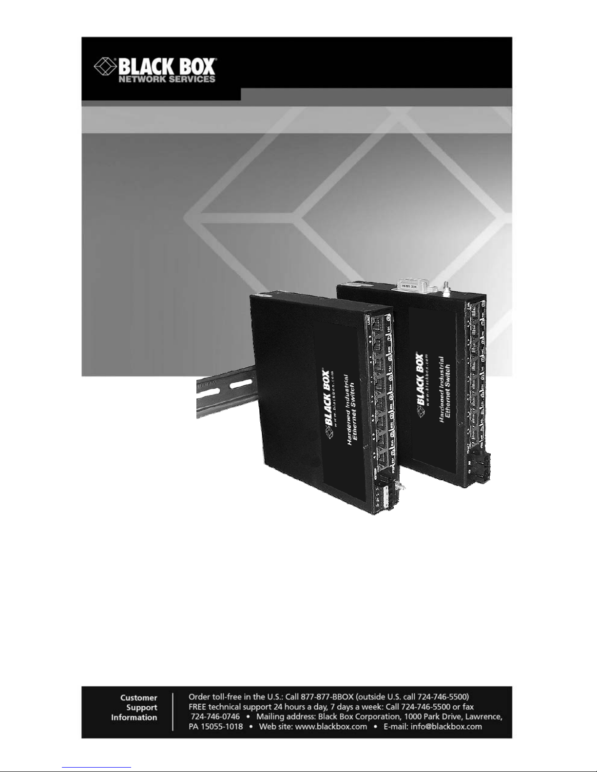
Hardened Industrial Switch
Provides eight 10/100 copper ports
and one 100-Mbps fiber uplink port.
Operation is plug-and-play.
Front-mounted LEDs provide status information on each port.
LBH081A LBH181A
LBH082A LBH182A
LBH084A LBH184A
Page 2

Radio Interference Regulations
724-746-5500 | blackbox.com
Page 2
Federal Communications Commission and Industry Canada Radio
Frequency Interference Statements
This equipment generates, uses, and can radiate radio-frequency energy, and if not
installed and used properly, that is, in strict accordance with the manufacturer’s
instructions, may cause interference to radio communication. It has been tested and
found to comply with the limits for a Class A computing device in accordance with the
specifications in Subpart B of Part 15 of FCC rules, which are designed to provide
reasonable protection against such interference when the equipment is operated in a
commercial environment. Operation of this equipment in a residential area is likely to
cause interference, in which case the user at his own expense will be required to take
whatever measures may be necessary to correct
the interference.
Changes or modifications not expressly approved by the party responsible for
compliance could void the user’s authority to operate the equipment.
This digital apparatus does not exceed the Class A limits for radio noise emission
from digital apparatus set out in the Radio Interference Regulation of Industry
Canada.
Le présent appareil numérique n’émet pas de bruits radioélectriqu es dépassant les
limites applicables aux appareils numériques de
la classe A prescrites dans le Règlement sur le brouillage radioélectrique publié par
Industrie Canada.
Page 3

NOM Statement
724-746-5500 | blackbox.com
Page 3
Instrucciones de Seguridad
(Normas Oficiales Mexicanas Electrical Safety Statement)
1. Todas las instrucciones de seguridad y operación deberán ser leídas antes de que el
aparato eléctrico sea operado.
2. Las instrucciones de seguridad y operación deberán ser guardadas para referencia
futura.
3. Todas las advertencias en el aparato eléctrico y en sus instrucciones de operación
deben ser respetadas.
4. Todas las instrucciones de operación y uso deben ser seguidas.
5. El aparato eléctrico no deberá ser usado cerca del agua—por ejemplo, cerca de la tina de
baño, lavabo, sótano mojado o cerca de una alberca, etc..
6. El aparato eléctrico debe ser usado únicamente con carritos o pedestales que sean
recomendados por el fabricante.
7. El aparato eléctrico debe ser montado a la pared o al techo sólo como sea recomendado
por el fabricante.
8. Servicio—El usuario no debe intentar dar servicio al equipo eléctrico más allá a lo
descrito en las instrucciones de operación. Todo otro servicio deberá ser referido a
personal de servicio calificado.
9. El aparato eléctrico debe ser situado de tal manera que su posición no interfiera su uso.
La colocación del aparato electric sobre una cama, sofá, alfombra o superficie similar puede
bloquea la ventilación, no se debe colocar en libreros o gabinetes
que impidan el flujo de aire por los orificios de ventilación.
10. El equipo eléctrico deber ser situado fuera del alcance de fuentes de calor como
radiadores, registros de calor, estufas u otros aparatos (incluyendo amplificadores) que
producen calor.
11. El aparato eléctrico deberá ser connectado a una fuente de poder sólo del tipo descrito en
el instructivo de operación, o como se indique en el aparato.
12. Precaución debe ser tomada de tal manera que la tierra fisica y la polarización del
equipo no sea eliminada.
13. Los cables de la fuente de poder deben ser guiados de tal manera que no sean
pisados ni pellizcados por objetos colocados sobre o contra ellos, poniendo particular
atención a los contactos y receptáculos donde salen del aparato.
14. El equipo eléctrico debe ser limpiado únicamente de acuerdo a las recomendaciones del
fabricante.
15. En caso de existir, una antena externa deberá ser localizada lejos de las lineas de
energia.
16. El cable de corriente deberá ser desconectado del cuando el equipo no sea usado por un
largo periodo de tiempo.
17. Cuidado debe ser tomado de tal manera que objectos liquidos no sean derramados
sobre la cubierta u orificios de ventilación.
18. Servicio por personal calificado deberá ser provisto cuando:
A: El cable de poder o el contacto ha sido dañado; u
B: Objectos han caído o líquido ha sido derramado dentro del aparato; o
C: El aparato ha sido expuesto a la lluvia; o
D: El aparato parece no operar normalmente o muestra un cambio en su
desempeño; o
E: El aparato ha sido tirado o su cubierta ha sido dañada
.
Page 4

Trademarks Used in this Manual
724-746-5500 | blackbox.com
Page 4
Trademarks Used in this Manual
Black Box and the Double Diamond logo are registered trademarks of BB
Technologies, Inc.
Ethernet is a trademark of Xerox Corporation
NEBS is a trademark of Telcordia Technologies
UL is a registered trademark of Underwriters Laboratories
Any other trademarks mentioned in this manual are acknowledged to be the property
of the trademark owners.
We‘re here to help! If you have any questions about your application
or our products, contact Black Box Tech Support at 724-746-5500
or go to blackbox.com and click on “Talk to Black Box.”
You’ll be live with one of our technical experts in less than 30 seconds.
Page 5

Table of Contents
724-746-5500 | blackbox.com
Page 5
Table of Contents
1.
SPECIFICATIONS .................................................................................. 6
1.1 Technical Specifications ................................................................ 6
1.2 Ordering Information ..................................................................... 8
2. INTRODUCTION ..................................................................................... 9
2.1 Inspecting the Package and Product ............................................ 9
2.2 Product Description - General ....................................................... 9
2.2.1 LBH18x chassis .............................................................. 11
2.2.2 LBH08x chassis .............................................................. 11
2.3 Fiber port, SC or LC Connector for Model LBH18x..................... 12
2.4 Frame Buffering and Latency ...................................................... 12
2.5 Features and Benefits ................................................................. 14
2.6 Applications ................................................................................. 15
3. INSTALLATION ..................................................................................... 17
3.1 Locating LBH08x/LBH18x Series Switches ............................... 17
3.1.1 Table Top or Shelf Mounting .......................................... 17
3.1.2 Mounting Dimensions with metal brackets ..................... 17
3.2 DIN-Rail mounting option ............................................................ 20
3.3 Connecting Ethernet Media ......................................................... 20
3.3.1 Connecting Twisted Pair (RJ-45, CAT 3 or CAT 5) ....... 21
3.3.2 Connecting Fiber Optic SC-type, “Snap-In” ................... 21
3.3.3 Connecting Fiber Optic LC-type,
“Small Form factor (SFF)” .............................................. 21
3.3.4 Connecting Single-Mode Fiber Optic ............................. 21
3.3.5 Power Budget Calculations for LBH18x Fiber Media ..... 22
3.3.6 Connections to NICs which support Auto-Negotiation ... 22
3.4 Powering the LBH08x/LBH18x .................................................... 22
4. OPERATION ......................................................................................... 23
4.1 Dual-Speed Functionality, and Switching .................................... 23
4.2 Auto-negotiation and Speed-sensing .......................................... 24
4.3 Auto-Cross (MDIX) and Auto-negotiation, for RJ-45 ports .......... 24
4.4 LED Indicators ............................................................................. 24
5. TROUBLESHOOTING .......................................................................... 25
5.1 Before Calling for Assistance ...................................................... 25
5.2 When Calling for Assistance ....................................................... 26
5.3 Return Material Authorization (RMA) Procedure ......................... 26
5.4 Shipping and Packaging Information .......................................... 27
APPENDIX A: WARRANTY INFORMATION ............................................... 27
APPENDIX B: DC Power Input ..................................................................... 28
Page 6

Chapter 1: Specifications
724-746-5500 | blackbox.com
Page 6
1. SPECIFICATIONS
1.1 Technical Specifications
Performance
Filtering / Forwarding Rate:
Ethernet (10Mbps): 14,880 pps
Fast Ethernet (100Mbps): 148,800 pps
Switching Processing Type: Store and Forward with IEEE 802.3x full-
duplex flow -control, non-blocking
Data Rate: 10Mbps and 100Mbps
Address Table Capacity: 4K node, self-learning with address agin g
Packet buffer size: 256 KB total
Latency: 5 μs + packet time (100 to 100Mbps)
Network Standards and Compliance, hardware
Ethernet V1.0/V2.0 IEEE 802.3: 10BASE-T,
IEEE 802.3u: 100Base-TX, 100BASE-FX
IEEE 802.1p: Priority protocol
IEEE 802.1d: Spanning tree protocol
IEEE 802.1w: Rapid Spanning tree protocol
IEEE 802.1q: VLAN Tagging
IEEE 802.3x: Flow Control
IEEE 802.3ad: Link Aggregation (Trunking)
IEEE 802.1x: Port based Network access control
Maximum 10 Mbps Ethernet Segment Lengths
Unshielded twisted pair - 100 m (328 ft)
Shielded twisted pair - 150 m (492 ft)
10BASE-FL multi-mode fiber optic - 2 km (6,562 ft)
10BASE-FL single-mode fiber optic - 10 km (32,810 ft)
Maximum Standard Fast Ethernet Segment Lengths:
10BASE-T (CAT 3, 4, 5 UTP) - 100 m (328 ft)
100BASE-TX (CAT 5 UTP) - 100 m (328 ft)
Shie lded twisted pair - 150 m (492 ft)
100BASE-FX, half-duplex, multi-mode - 412 m (1350 ft)
100BASE-FX, full-duplex, multi-mode - 2.0 km (6,562 ft)
100BASE-FX, half-duplex, single-mode - 412 m (1350 ft)
100BASE-FX, full-duplex, single-mode - 20.0 km (66K ft)
100BASE-FX, full-duplex, Long Reach - 40.0 km (122K ft)
Fiber Multi-mode connector types supported:
Fiber Port, LC-type (plug-in): MLC SFF Fiber multi-mode 100BASE-FX
Fiber Port, SC-type (plug-in), MSC multi-mode 100BASE-FX
Fiber Single-mode connector types:
Fiber Port, LC-type, Fiber SLC and SLCL SFF single-mode, 100BASE-FX
Fiber Port, SC-type, single-mode, SSC and SSCL SFF 100BASE-FX
Page 7

Chapter 1: Specifications
724-746-5500 | blackbox.com
Page 7
LED Indicators
(on chassis) PWR: Steady On when power applied
(per port) SPEED: ON (100Mbps), OFF (10Mbps)
LINK/ACT: ON (Link), BLINKING (Activity)
F/H: ON (Full-Duplex), OFF (Half-Duplex)
Operating Environment
Ambient Temperature:
13° to 140° F (-25° to 60°C)
Storage Temperature: -58°to 167°F (-50°to 75°C)
Ambient Relative Humidity: 10% to 95% (non-condensing)
Altitude: -200 to 13,000 ft. (-60 to 4000m)
Conformal Coating (humidity protection) optional: Request quote
Packaging
Enclosure: High strength sheet metal
Dimensions: 1.25 in H x 6.6 in W x 6.0 in D
(3.18 cm H x 16.76 cm W x 15.24 cm D)
Cooling method: Convection
Weight: 1 lb. (454 g)
DC Power Supply (Internal, floating ground)
DC Power Connector: Terminal block
12VDC Power Input nominal (range 9 to 15VDC)
24VDC Power Input nominal (range 18 to 36VDC)
-48VDC Power Input nominal (range 36 to 60VDC)
Std. Terminal Block : “ -, GND, + ”
Power Consumption:
8 watts Typical. , 9 watts Max.
Mounting:
Suitable for wall or DIN-Rail mounting
Agency Approvals and Standards Compliance:
UL listed (UL60950), cUL, CE, Emissions meet FCC Part 15 Class A
NEBS Level 3 and ETSI Compliant
Warranty: Three years, per UL 60950 temperature rating Made in USA
Email
info@Blackbox.com for additional information.
Page 8

Chapter 1: Specifications
724-746-5500 | blackbox.com
Page 8
1.2 Ordering Information
MODEL DESCRIPTION
LBH082A-H: Hardened Industrial Switch with 24VDC power input, eight
10/100Mbps switched RJ45 ports; panel-mount brackets
included
LBH082A-HD: Same as LBH082A-H except a DIN-Rail bracket is included
LBH081A-H: Same as LBH082A-H except the power input is 12VDC
LBH081A-HD: Same as LBH081A-H except a DIN-Rail bracket is included
LBH084A-H: Same as LBH082A-H except the power input is -48VDC
LBH084A-HD: Same as LBH084A-H except a DIN-Rail bracket is included
LBH182A-H-ff: Hardene d Industrial Switch with 24VDC power input, eight
10/100Mbps switched RJ45 ports, one 100Mbps Fiber port and
Wall mount brackets included
LBH182A-HD-ff: Same as LBH182A-H except a DIN-Rail bracket is included
LBH181A-H-ff: Same as LBH182A-H except the power input is 12VDC
LBH181A-HD-ff: Same as LBH181A-H except a DIN-Rail bracket is included
LBH184A-H-ff: Same as LBH182A-H except the power input is -48VDC
LBH184A-HD-ff: Same as LBH184A-H except a DIN-Rail bracket is included
Fiber Port Connectors:
(“ff” selections of the “fiber flavor”)
“SC” = 100Base-FX, multi-mode, SC type, 2km
“LC” = 100Base-F X, multi-mode, LC type, 2km
“SSC20” = 100Base-FX, single-mode, SC type, 20km
“SSC40” = 100Base-FX, single-mode, SC type, “Long Reach” 40km
“SLC20” = 100Base-FX, single-mode, LC type, 20km
“SLC40” = 100Base-FX, single-mode, LC type, “Long Reach” 40km
Page 9

Chapter 2: Introduction
724-746-5500 | blackbox.com
Page 9
2. INTRODUCTION
2.1 Inspecting the Package and Product
Examine the shipping contain er for obvious damage prior to installing this
product; notify the carrier of any damage that you believe occurred during shipment
or delivery. Inspect the contents of this package for any signs of damage and ensure
that the items listed below are included.
This package should contain:
1 Hardened Switch (LBH182, LBH181 or LBH184) with a Fiber Port, or
Hardened Switch (LBH082, LBH081 or LBH084) with all copper ports.
1 Set of metal clips and screws for secure shelf or wall-mounting
1 Installation and User Guide
Remove the Hardened Industrial Switch from the shipping container. Be
sure to keep the shipping container should you need to ship the unit at a later date.
In the event there are items missing or damage d, contact your supplier. If
you need to return the unit, use the original shipping container. Refer to Chapter 5,
Troubleshooting, for specific return procedures.
2.2 Product Description - General
In factory automation control systems, field bus control systems are givi ng
way to IP-based networks. The Hardened Industrial switch provides modern Ethernet
connectivity for a variety of factory automation and SCADA applications.
The Black Box LBH18x series Hardened switch provides eight 10/100
copper ports and one 100Mbps fiber up-link port. They are hardened to withstand the
stress of industrial environments, highly reliable (over 25 ye ars MTBF), and are easily
fitted into industrial and telecom control cabinets. Operation is “plug-and-play.” Frontmounted LEDs provide status information on each port. Multiple LBH18x series
switches can be linked in a cascaded or “daisy-chain” manner for expansion of the
network.
The fiber port is available with a 2KM multi-mode SC or LC-type connector,
or with a single-mode LC, SC-type to support 20 and 40 kilometers distance. The
100Mbps fiber port of the LBH18x supports full distance fiber LAN cabling to a wiring
closet switch upstream.
Page 10

Chapter 2: Introduction
724-746-5500 | blackbox.com
Page 10
The LBH08x/LBH18x-Series industrial grade switch is DC-powered by
24VDC for factory floor or 48VDC for telco carrier field facilities, has a rugged metal
case and metal mounting brackets suitable for panel mounting. Models with a DINRail mounting bracket included are available. T he LBH08x/LBH18x industrial
hardened switches and the other Black Box industrial networking products are
backed by a three-year warranty.
Industrial switches can connect a group of Ethernet-ready, process control
units to a central control switch or to backhaul aggregated data from a cluster of edge
switches that is typical in telecommunication environment. These switches offer real
time control and input-output data flow through factory floor and are easy to bring-up
because they are standards-based. These switches also are ideal for cell phone
backhaul using faster and longer-range fiber cable. T ypically DIN-rail mounted, these
switches can withstand factory floor temperatures and telco central office
environment and can be used without any special enclosures, fans or heaters.
The LBH08x/LBH18x are easy to install and use. Addresses of attached
nodes are automatically learned and maintai ned, adapting the switching services to
network changes and expansions to provide plug-and-play operation. Flow control
maximizes throughput across all ports. Front-mounted LEDs provide status
information on each port.
The LBH18x model has one full-duplex 100Mbps switched fiber port, and
eight switched 10/100 full/half auto-negotiating RJ-45 ports. While the s witched fiber
port is typically for a backbone connection, the switched RJ-45 ports can be used to
connect a central control switch to various process control equipment or to aggregate
data from a group of edge switches.
Page 11

Chapter 2: Introduction
724-746-5500 | blackbox.com
Page 11
Fig 2.2a LBH082A-H and LBH182A-H-SC models shown
2.2.1 LBH18x chassis with SC or LC Fiber port
The LBH18x chassis houses one main PC board. The front side of the
chassis has eight RJ-45 twisted-pair ports and one 100Mbps fiber port, located at the
left front of the unit. Port #9 supports fiber ports only.
LEDs to indicate operating status of all ports are located on the front face
per port. There is a power (PWR) indicator for the unit. For each port, there are Link
and Activity (LINK/ACT) LEDs indicating traffic, and speed (ON for 100Mbps), and
full/half (F/H) duplex indicators.
The DC power terminal block is located at the right side of the chassis,
looking at the front. DC power option inputs are 12, 24 and -48VDC.
2.2.2 LBH08x chassis with all RJ-45 Copper ports
The LBH08x chassis houses one main PC board. The front side of the
chassis has eight twisted-pair switched ports. All RJ-45 ports are Auto-negotiating
and Auto-Cross MDI-MDIX.
LEDs to indicate operating status of all ports are located on the front face
per port. There is a power (PWR) indicator for the unit. For each port, there are Link
and Activity (LINK/ACT) LEDs indicating traffic, and speed (ON for 100Mbps), and
full/half (F/H) duplex indicators.
The DC power terminal block is located at the left front side of the chassis.
DC power option inputs are 12, 24 and -48VDC.
Page 12

Chapter 2: Introduction
724-746-5500 | blackbox.com
Page 12
2.3 Fiber port, SC or LC Connector for Model LBH18x
The Fast Ethernet fiber port on the LBH18x is set to operate at fixed
100Mbps speed for guaranteed high performance. The LBH18x fiber port is factorybuilt as either a multi-mode SC, LC or single-mode SC or LC connector. The
100Mbps fiber port will run at 100Mbps speed at all times. The 100Mbps fiber port is
a switched port and performs as a domain, providing a high bandwidth backbone
connection (no media converter is required!) and supporting long (up to 40km) fiber
cable distances for installation versatility.
On LBH18x units, there are two LED’s for the fiber port. One (LK/ACT) is
steady ON to indicate LINK, blinking indicates the port is transmitting and receiving.
The F/H indicates full-duplex when ON, when it is OFF, operation is half-duplex.
A fiber cable must be connected to the 100Mbps port and a proper link (LK
lit) must be made with the device at the other end of the cable in order for these LEDs
to provide valid indications of operating conditions.
2.4 Frame Buffering and Latency
The LBH08x/LBH18x are store-and-forward switches. Each frame (or
packet) is loaded into the Switch’s memory and inspected before forwarding can
occur. This technique ensures that all forwarded frames are of a valid length and
have the correct CRC, i.e., are good packets. This eliminates the propagation of ba d
packets, enabling all of the available bandwidth to be used for valid information.
While other switching technologies such as "cut-through" or "express"
impose minimal frame latency, they will also permit bad frames to propagate out to
the Ethernet segments connected. The "cut-through" technique permits collision
fragment frames, which are a result of late collisions, to be forwarded to add to the
network traffic. Since there is no way to filter frames with a bad CRC (the entire
frame must be present in order for CRC to be calculated), the result of indiscriminate
cut-through forwarding is greater traffic congestion, especially at peak activity. Since
collisions and bad packets are more likely when traffic is heavy, the result of storeand-forward operation is that more bandwidth is available for good packets when the
traffic load is greatest.
To minimize the possibility of dropping frames on congested ports, each
LBH08x/LBH18x Industrial Switch dynamically allocates buffer space from a 1MB
memory pool, ensuring that heavily used ports receive ver y large buffer space for
packet storage. (Many other switches have their packet buffer storage space divided
evenly across all ports, resulting in a small, fixed number of packets to be st ored per
port. When the port buffer fills up, dropped packets result.) This dynamic buffer
allocation provides the capability for the maximum resources of the LBH08x/LBH18x
unit to be applied to all traffic loads, even when the traffic activity is unbalanced
across the ports. Since the traffic on an operating network is constantly varying in
packet density per port and in aggregate den sity, the Industrial Switches are
constantly adapting internally to provide maximum network performance with the
least dropped packets.
Page 13

Chapter 2: Introduction
724-746-5500 | blackbox.com
Page 13
When the Switch detects that its free buffer queue space is low, the Switch
sends industry standard (full-duplex only) PAUSE packets out to the devices sending
packets to cause “flow control”. This tells the sending devices to temporarily stop
sending traffic, which allows a traffic catch-up to occur without dropping packets.
Then, normal packet buffering and processing resumes. This flow-control sequence
occurs in a small fraction of a second and is transparent to an observer.
Another feature implemented in the LBH08x/LBH18x Industrial Switch is a
collision-based flow-control mechanism (when operating at half-duplex only). When
the Switch detects that its free buffer queue space is low, the Switch prevents more
frames from entering by forcing a collision signal on all receiving half-du plex ports in
order to stop incoming traffic.
The latency (the time the frame spends in the Switch before it is sent along
or forwarded to its destination) of the LBH08x/LBH18x Industrial Switch varies with the
port-speed types, and the length of the frame is a variable here as it is with all storeand-forward switches. For 10 Mbps-to-10 Mbps or 10 Mbps-to-100Mbps or 100Mbpsto-10 Mbps forwarding, the latency is 15 microseconds plus the packet time at 10
Mbps. For 100Mbps-to-100Mbps forwarding, the latency is 5 microseconds plus the
packet time at 100Mbps.
Page 14

Chapter 2: Introduction
724-746-5500 | blackbox.com
Page 14
2.5 Features and Benefits
100Mbps switching services for factory automation Ethernet LANs
LBH08z/LBH18x Switches provide Fast Ethernet s witching on all ports.
They perform high speed filter/forward operations on the traffic, giving
each port’s segment a full 100Mbps (or 10 Mbps) of bandwidth.
Option for one “future-proof” fiber backbone port connector,
Model LBH18x
Built-in fiber ports may be ordered with 100Mbps full-duplex multi-mode
SC, LC and single-mode SC and LC connectors.
Model LBH08x with all RJ-45 (copper) ports
RJ-45 ports provide twisted pair segment connections, with auto-
negotiation and auto-cross MDI-MDIX functionality. All RJ-45 ports are
capable of half- or full-duplex.
Installation is “Plug and Play”, operation is transparent to software
The LBH08x/LBH18x operates as a hardwar e switch, only forwarding
those packets from each domain that are needed on the other domains.
Internal address tables are self-learning, enabling users to change port
connections or 10/100 domains without affecting operations.
Heavy-duty design for Industrial Ethernet and extended
temperature operation
Fiber ports take more power than copper ports, but the LBH08x/LBH18x
Series design provides for this with heavy-duty components. The
LBH08x/LBH18x is designed for industrial use, is an enclosed
convection-cooled package, and is UL rated at -25°C to 60°C ambient
sustained temperatures.
Page 15

Chapter 2: Introduction
724-746-5500 | blackbox.com
Page 15
2.6 Applications
The LBH08x and LBH18x are designed to bring future-proof fiber
connectivity and widely- used copper connectivity to factory automation control
systems, field bus control systems and many other industrial network environments.
Ethernet networks in factory control systems provide interoperability and
bandwidth with universal connectivity via 10/100 RJ-45 ports, all at an eco nomical
cost. In control system cabinets, a small group of IEDs, PLCs, sensors, WAPs and
control devices are co-located and connected into the net work using twisted-pair
copper cabling. Then, this group of devices is linked into the overall industrial
network, typically with a fiber cable for noise immunity and distance. The
LBH08x/LBH18x-Series Hardened Ethernet Switches are ideal for these applications.
Example 1. LBH18x for industrial application
Equipped with lots of useful features includin g hardened enclosures, a wide
spread of DC power supply options, and extended temperature ratin gs qualifies the
LBH08x/LBH18x Series Industrial switch for any Industrial factory-floor.
In an Industrial environment where the factory floors are networked with
Ethernet based mixed-media LANs and equipped with PLC computers to take
readings and data from M/C Client/ Server databases and transport this important
data to the central office data warehouses, the LBH08x/LBH18x Series shines. The
LBH08x/LBH18x features handle these kinds of networks very securel y and reliably
throughout the Factory-floors. The DIN-Rail Mounting options, allow the Industrial
Factory floor user to mount the LBH08x/LBH18x securely anywhere on their Network
setup.
Page 16

Chapter 2: Introduction
724-746-5500 | blackbox.com
Page 16
Where there are existing 10 Mbps hubs or switch users, they can easily be
cascaded into any port of the LBH18x. This allows a simple plug-and-play addition of
100Mbps ports to an existing 10 Mbps network without having to change it. Nodes
that are capable of 100Mbps speed can be moved to a LBH18x port, and will
automatically operate at the higher speed.
The 100Mbps fiber port on the LBH18x can be used for accommodating
high performance data transfers, and provides fiber connectivity built-in rather than
needing an auxiliary media converter unit. The 100Mbps traffic does not use the
bandwidth of the 10 Mbps domain, so overall performance of the network is sustained
at the highest possible level.
Example 2. LBH08x for office installation
In this example, the LBH08x Switch is used to serve a small office in a
factory with multi-servers, print server, internet access and mixed-speed
requirements. The users operate at 100Mbps as well as at 10 Mbps, and utility
devices (such as print servers) run at 10 Mbps. High performance users need a high
bandwidth up-link for access to a central LAN and central file servers. Any attached
node can change speed at any time without affecting network operation or impacting
other users. The multi-functional LBH08x switches provide this solution very
efficiently and economically. Various features included MDIX, plug-n-play, Din-Rail
mountings and dual LEDs make this compact switch a very effective solution for this
requirement.
Page 17

Chapter 3: Installation
724-746-5500 | blackbox.com
Page 17
3. INSTALLATION
Before installing the equipment, it is necessary to take the following precautions:
1.) If the equipment is mounted in an enclosed or multiple rack assembly, the
steady-state long-term environmental temperature around the equipment must
be less than or equal to 600C.
2.) If the equipment is mounted in an enclosed or multiple rack assembly, adequate
airflow must be maintained for proper and safe operation.
3.) If the equipment is mounted in an enclosed or multiple rack system, placement
of the equipment must not overload or load unevenly the rack system.
4.) If the equipment is mounted in an enclosed or multiple rack assembly, verify the
equipment’s power requirements to prevent overloading of the building/s
electrical circuits.
5.) If the equipment is mounted in an enclosed or multiple rack assembly verify that
the equipment has a reliable and uncompromised earthing path
.
This section describes installation of the LBH08x/LBH18x Switches, as well as
connection of the various Ethernet media types.
3.1 Locating LBH08x/LBH18x Series Switches
For vertical panel mounting and wall mounting, see Section 3.1.2
For vertical DIN-Rail mounting, see Section 3.2
For DC power input data, see Appendix B.
The rugged metal case of the LBH08x/LBH18x will normally protect it from
accidental damage in a lab or workplace setting. Maintain an open view of the front
to visually monitor the status LEDs. Keep an open area around the unit so that
cooling can occur from convection while the unit is in operation. The switch has no
fans, so it is silent when in operation. Internal electronics use the case as a heat
sink, so the unit may normally be quite warm to the touch.
3.1.1 Table Top or Shelf Mounting
The LBH08x/LBH18x Industrial switch can be easily mounted on a table-top
or any suitable horizontal surface, and has four rubber feet to provide stabilit y without
scratching finished surfaces.
3.1.2 Mounting Dimensions with metal brackets
Each LBH08x/LBH18x switch is supplied with metal mounting brackets and
screws to mount the unit securely on a panel or wall. It is recommended to mount the
switch vertically in the mounting position shown below, for proper cooling a nd long-life
reliability. It is also advisable to mount the unit with space for air movement around
the top and the sides, typically a minimum of 1 inch.
Page 18

Chapter 3: Installation
724-746-5500 | blackbox.com
Page 18
Note: The metal brackets supplied, hold the back of the switch out from the
panel or wall behind it, creating a rear space of about 1/8 inch or 3mm. This
allows air circulation and cooling of the rear part of the case.
For best cooling of the switch, attach the metal brackets to metal (rather than
wood or plastic). Attaching to metal helps conduct heat away from the switch
through the metal brackets and into the metal support structure.
Fig 3.1.2a LBH18x mounting dimensions
Page 19

Chapter 3: Installation
724-746-5500 | blackbox.com
Page 19
Fig 3.1.2b LBH08x mounting dimensions
Page 20

Chapter 3: Installation
724-746-5500 | blackbox.com
Page 20
3.2 DIN-Rail mounting option
The LBH08x/LBH18x is desig ned for use in a “factory floor” industrial
environment. It is available with an optional DIN-Rail bracket to mount it securely in a
metal factory floor enclosure, maintained vertically for proper convection cooling of
the unit. The LBH08x/LBH18x requires one
DIN-Rail bracket for secure mounting. See
a LBH08x viewed from the bottom, at the
rear, showing the DIN Rail in place.
The DIN Rail bracket is mounted to
the bottom of the LBH08z/LBH18x unit, as
shown. Four threaded holes are provided
on the bottom of the unit for DIN-Rail
mounting purposes. The required four
screws are included with the DIN-Rail
bracket, and are no.4-40 x 9/32 PHIL. PAN
Head. The rail clip is spring-loaded with a
pull-up latch at the top for easy “snap-on”
attachment and removal. The
LBH08x/LBH18x models with “HD” have the
DIN Rail bracket included and assembled on
the unit at the factory.
3.3 Connecting Ethernet Media
The LBH08x/LBH18x Switches are specifically designed to support standard
Ethernet media types within a single Switch unit. This is accomplished by using a
choice of five popular Fiber Connectors which can be individually selected and
configured.
The various media types supported along with the corresponding IEEE
802.3, and 802.3u standards and connector types are as follo ws:
Media
IEEE Standard Connector
Twisted Pair (CAT 3 or 5) 10BASE-T RJ-45
Twisted Pair (CAT 5) 100BASE-TX RJ-45
Fiber (Multi-mode) 100BASE-FX LC, SC
Fiber (Single-mode) 100BASE-FX LC, SC
NOTE : It is recommended that high quality CAT. 5 cables (which work for
both 10 Mbps and 100Mbps) be used whenever possible in order to provide
flexibility in a mixed-speed network, since LBH08x/LBH18x Series Switch ports
are auto-sensing for either 10 and 100Mbps. Note that the auto-sensing
function does not sense the cable type.
Page 21

Chapter 3: Installation
724-746-5500 | blackbox.com
Page 21
3.3.1 Connecting Twisted Pair (RJ-45, CAT 3 or CAT 5)
(Unshielded or Shielded)
The following procedure describes how to connect a 10BASE-T or
100BASE-TX twisted pair segment to the RJ-45 port. The procedure is the same for
both unshielded and shielded twisted pair cables.
1. Using standard twisted pair media, insert either end of the cable with a RJ-45
plug into the RJ-45 connector of the port. Note that, even though the connector
is shielded, either unshielded or shielded cables and wiring may be used.
2. Connect the other end of the cable to the corresponding de vice.
3. Use the LINK LED to ensure proper connectivity by noting that the LED will be
illuminated when the unit is powered and proper connection is established. If
this does not help, ensure that the cable is connected properly and that the
device on the other end is powered and is not defective.
3.3.2 Connecting Fiber Optic SC-type, “Snap-In”
The following procedure applies to installations using SC-type fiber
connectors. This procedure applies to ports using SC fiber connectors.
1. Before connecting the fiber optic cable, remove the protective dust caps from
the tips of the fiber connectors. Save these dust caps for future use.
2. Wipe clean the ends of the dual connectors with a soft cloth or lint-free lens
tissue dampened in alcohol. Make certain the connectors are clean before
connecting.
3. Snap the two square male connectors into the SC female jacks of the Fiber
connector until it clicks and secures.
4. The LINK LED on the front of the fiber connector will illuminate when a proper
connection has been established at both ends (and when power is ON in the
unit).
3.3.3 Connecting Fiber Optic LC-type, “Small Form factor (SFF)”
The following procedure applies to installations using LC-type fiber
connectors, i.e., using LC single-mode. While connecting fiber media to LC
connectors, simply snap the two square male connectors into the LC female jacks of
the Fiber connector until it clicks and secures.
3.3.4 Connecting Single-Mode Fiber Optic
When using single-mode fiber cable, be sure to use single-mode fiber port
connectors. Single-mode fiber cable has a smaller diameter than multi-mode fiber
cable (9/125 microns for single-mode, 50/125 or 62.5/125 microns for multi-mode
where xx/xx are the diameters of the core and the core plus the cladding
respectively). Single-mode fiber allows full bandwidth at longer distances, about
20Km with the multi-mode SC.
The same procedures as for multi-mode fiber apply to single-mode fiber
connectors. Follow the steps listed in Section 3.3.2 above.
Page 22

Chapter 3: Installation
724-746-5500 | blackbox.com
Page 22
3.3.5 Power Budget Calculations for LBH18x Fiber Med i a
Receiver Sensitivity and Transmitter Power are the parameters necessary to
compute the power budget. To calculate the power budget of different fiber media
installations using Black Box products, the following equations should be used:
OPB (Optical Power Budget) = P
T
(min) - PR(min)
where P
T
= Transmitter Output Power, and PR = Receiver Sensitivity
Worst case OPB = OPB - 1dB(for LED aging) - 1dB(for insertion loss)
Worst case distance = {Worst case OPB, in dB} / [Cable Loss, in dB/Km]
where the “Cable Loss” for 62.5/125 and 50 /125
μm (m.m.) is 2.8 dB/km,
and the “Cable Loss” for 100/140 (Multi-mode) is 3.3 dB/km,
and the “Cable Loss” for 9/125 (Single-mode) is 0.5 dB/km
* Note: The use of either multi-mode or single-mode fiber to operate at 100Mbps
speed over long distances (i.e., over approx. 400 meters) can be achieved
only if the following factors are both applied:
• The 100Mbps fiber segment must operate in full-duplex (FDX) mode, and
• The worst-case OPB of the fiber link must be greater than the fiber cable’s
passive Attenuation.
(Attenuation = Cable loss + LED aging loss + Insertion loss + safety factor
3.3.6 Connections to NICs which support Auto-Negotiation
The copper ports of LBH08x/LBH18x Industrial Switches will function
properly with NICs (Network Interface Cards) which support Auto-Negotiation, and
the Fast Link Pulse (FLP) coding for the 100BASE-TX signaling system. When
connecting a NIC to the LBH08x/LBH18x, it may be necessary to reload the NIC
drivers on the user device if the NIC has been communicating with a protocol other
than 100BASE-TX (such as 10BASE-T). When 100Mbps oper ation is agreed and in
use, the SPEED LED is illuminated steady ON. It is OFF if there is no traffic or if 10
Mbps traffic.
3.4 Powering the LBH08x/LBH18x
The DC internal power suppl y supports installation environments where the
DC voltage is from 9 to 60 volts depending on the model selected. When connecting
the Ethernet cabling, there is no need to power down the unit. Individual cable
segments can be connected or disconnected without concern for power-related
problems or damage to the unit.
Power input options are available to suit the LBH08x/LBH18x Switches to
special high-availability communications and/or heavy industrial-grade applications,
including:
* 12VDC, -48VDC and 24VDC with single DC input
Page 23

Chapter 4: Operation
724-746-5500 | blackbox.com
Page 23
4. OPERATION
This chapter describes the functions and operation of the LBH08x/LBH18x Switch.
4.1 Dual-Speed Functionality, and Switching
The LBH08x/LBH18x Hardened Industrial Switches provide eight switched
ports, one of which may be 100Mbps fiber on the Model LBH18x. The architecture
supports a dual-speed switching environment, with a built-in full-duplex “future-proof”
fiber port. The Model LBH08x has RJ-45 copper on all the ports with auto-negotiation
capability.
The switched RJ-45 ports are full-duplex and auto-sensing for speed. (See
section 2.2). When the connected device is 10 Mbps, the LBH18x obeys all the rules
of 10 Mbps Ethernet configurations. The 10 Mbps users share a 10 Mbps traffic
domain, and can “communicate with” 100Mbps users as well as 100Mbps domai n.
Similarly, the 100Mbps traffic obeys the rules of 100Mbps Ethernet, and can
communicate with 10 Mbps domain too.
The LBH08x/LBH18x units are plug-and-play devices. There is no software
configuring to be done at installation or for maintenance. The internal functions of
both are described below.
Switching, Filtering and Forwarding
Each time a packet arrives on one of the switched ports, the decision is
taken to either filter or to forward the packet. Packets whose source and destination
addresses on the same port segment will be filtered, constraining them to one port
and relieving the rest of the network from processing them. A packet whose
destination address is on another port segment will be forwarded to the appropriate
port, and will not be sent to the other ports where it is not needed. Packets needed
for maintaining the operation of the network (such as occasional multi-cast packets)
are forwarded to all ports.
The LBH08x/LBH18x Industrial Switches operate in the store-and-forward
switching mode, which eliminates bad packets and enables peak performance to be
achieved when there is heavy traffic on the network.
Switching, Address Learning
The LBH08x/LBH18x units have address table capacity of 4K node
addresses, and are suitable for use in large networks. They are self-learning, so that
as nodes are added or removed or moved from one segment to another, the switch
automatically keeps up with node locations.
An address-aging algorithm causes least-used addresses to fall out in favor
of new frequently-used addresses. To reset the address buffer, cycle power downand-up.
Page 24

Chapter 4: Operation
724-746-5500 | blackbox.com
Page 24
4.2 Auto-negotiation and Speed-sensing
All eight RJ-45 ports independently support auto-negotiation for speed in
10BASE-T and 100BASE-TX modes. Operation is according to the IEEE 802.3u
standard.
When a RJ-45 cable connection is made, and each time a LINK is enabled,
auto-negotiation takes place. The LBH08x/LBH18x advertises its capab ility for 10 or
100 Mbps speed, and the device at the other end of the cable should similarly
advertise / respond and both sides will agree to the speed being used. Depending
upon the device connected, this will result in agreem ent to operate at either 10 Mbps
or 100Mbps speed.
When the ‘LINK/ACT’ LED is ON, steady ON indicates LINK with no traffic,
blinking ON indicates the port is transmitting / receiving. The port has auto-negotiated
for operation. (If a LBH08x or LBH18x RJ-45 port is connected to a non-negotiating
device, it will default to 10 Mbps speed and half-duplex mode, per the IEEE 802.3u
standard).
4.3 Auto-Cross (MDIX) and Auto-negotiation, for RJ-45 ports
The RJ-45 ports independently support auto-cross (MDI or MDIX) in
auto-negotiation mode and will work properly with all the other conn ected devices
with RJ-45 ports whether they support auto-negotiation (e.g., 10Mbps hub, media
converter) or fixed mode at 10Mbps or 100Mbps Half/Full Duplex (managed
switch) or not. No cross-over cable is required while using the LBH08x/LBH18x
copper port to other devices. Operation is according to the IEEE 802.3u standard.
4.4 LED Indicators
PWR: Illuminates GREEN, steady on when power applied.
10/100: Per port, ON = 100Mbps; OFF = 10 Mbps
(when LINK is made)
LINK/ACT: Per port, steady ON for LINK with no traffic, blinking
indicates port is transmitting and receiving.
F/H: ON = Full-Duplex and Link,
OFF = Half-Duplex and / or no Link
Page 25

Chapter 5: Troubleshooting
724-746-5500 | blackbox.com
Page 25
5. TROUBLESHOOTING
All Black Box Ethernet product s are designed to provide reliability and
consistently high performance in all network environments. The installation of Black
Box LBH08x and LBH18x Industrial Switch is a straightforward proced ure (see
INSTALLATION, Section 3.0); the operation is also straightforward and is discussed
in Section 4.
Should problems develop during installation or operation, this section is
intended to help locate, identify and correct these types of problems. Please follow
the suggestions listed below prior to contacting your supplier. However, if you are
unsure of the procedures described in this section or if the Black Box
LBH08x/LBH18x Industrial Switch is not performing as expected, do not attempt to
repair the unit; instead contact your supplier for assistance or contact Black Box
Customer Support.
5.1 Before Calling for Assistance
1. If difficulty is encountered when installing or operating the unit, refer back to
the Installation Section of the applicable chapter of this manual. Also check
to make sure that the various components of the network are interoperable.
2. Check the cables and connectors to ensure that they have been properly
connected and the cables/ wir es have not been crimped or in some way
impaired during installation. (About 90% of network downtime can be
attributed to wiring and connector problems.)
3. If the problem is isolated to a network device other than the LBH08x/LBH18x
Industrial Switch product, it is recommended that the problem device is
replaced with a known good device. Verify whether or not the problem is
corrected. If not, go to Step 4 below. If the problem is corrected, the
LBH08x/LBH18x Industrial Switch and its associated cables are functioning
properly.
4. If the problem continues after completing Step 3 above, contact your
supplier of the LBH08x/LBH18x Industria l Switch unit or if unknown, contact
Black Box Tech support (see pag e 4 of this guide) for assistance.
Page 26

Chapter 5: Troubleshooting
724-746-5500 | blackbox.com
Page 26
5.2 When Calling for Assistance
Please be prepared to provide the following information.
1. A complete description of the problem, including the following points:
a. The nature and durati on of the problem;
b. Situations when the problem occurs;
c. The components involved in the problem;
d. Any particular application that, when used, appears to create the
problem;
2. An accurate list of Black Box product model(s) involved, with serial
number(s). Include the date(s) that you purchased the products from your
supplier.
3. It is useful to include other network equipment models and related hardware,
including personal computers, workstations, terminals and printers; plus, the
various network media types being used.
4. A record of changes that have been made to your network configuration
prior to the occurrence of the prob lem. Any changes to system
administration procedures should all be noted in this record.
5.3 Return Material Authorization (RMA) Procedure
All returns for repair must be accompanied by a Return Material
Authorization (RMA) number. To obtain an RMA number, please contact Black Box
Tech support.
Please have the following information readily available:
Name and phone number of your contact person.
Name of your company / institution
Your shipping address
Product name
Serial Number (or Invoice Number)
Packing List Number (or Sales Order Number)
Date of installation
Failure symptoms, including a full description of the problem.
Black Box will carefully test and evaluate all returned products, will repair
products that are under warranty at no charge, and will return the warrantyrepaired units to the sender with shipping charges prepaid (see Warranty
Information, Appendix A, for complete details). However, if the problem or
condition causing the return cannot be duplicated by Black Box, the u nit will be
returned as:
No Problem Found.
Page 27

Chapter 5: Troubleshooting
724-746-5500 | blackbox.com
Page 27
Black Box reserves the right to charge for the testing of non-defective
units under warranty. Testing and repair of product that is not under warranty will
result in a customer (user) charge.
5.4 Shipping and Packaging Information
Should you need to ship the unit back to Black Box, please follo w these instructions:
1. Package the unit carefully. It is recommended that you use the original
container if available. Units should be wrapped in a "bubble-wrap" plastic
sheet or bag for shipping protection. (You may retain all connectors and
this Installation Guide.)
CAUTION: Do not pack the unit in Styrofoam "popcorn" type packing
material. This material may cause electro-static shock damage to the
unit.
2. Clearly mark the Return Material Authorization (RMA) number on the
outside of the shipping container.
3. Black Box is not responsible for your return shipping charges.
4. Ship the package to:
Black Box Network Services
(contact Black Box Tech support for information)
APPENDIX A: WARRANTY INFORMATION
Black Box warrants its products to be free from defects in materials and
workmanship for a period of three (3) years from the date of shipment.
During this warranty period, Black Box will repair or, at its option,
replace components in the products that prove to be defective at no charge
other than shipping and handling, provided that the product is returned prepaid to Black Box.
This warranty will not be effective if, in the opinion of Black Box, the
product has been damaged by misuse, misapplication, or as a result of service
or modification other than by Black Box.
Black Box reserves the right to make a charge for handling and
inspecting any product returned for warranty repair which turns out not to be
faulty.
Page 28

Appendix B
724-746-5500 | blackbox.com
Page 28
APPENDIX B: DC Power Input
B1.0 Specifications for LBH08x/LBH18x Switches, DC Power at 12, 24 and
–48VDC Power input
Each Black Box LBH08x/LBH18x Switch requires DC power input, at 12, 24
and 48VDC. The wide range of DC power input types qualifies this product for use in
12, 24 and 48 applications in different industries.
DC Power Terminals: “+”, “
-” are internally floating so that user may ground either
GND: ground wire connection to the chassis (#6-32 thread)
Power Consumption:
8 watts typical, 9 watts Max.
12VDC Power Input nominal (range 9 to 15VDC)
24VDC Power Input nominal (range 18 to 36VDC)
-48VDC Power Input nominal (range 36 to 60VDC)
B2.0 12, 24 and –48VDC
POWER, THEORY OF
OPERATION
The 12, 24 and 48VDC power options are
designed using diodes inside
on each DC power input line
behind the two external power
connection terminals, so that the power from an external source can only flow into the
hub. This allows the Switch to operate only whenever DC power is correctly applied
to the two inputs. It protects the Switch from incorrect DC input connections. An
incorrect polarity connection, for example, will neither affect the Switch, its internal
power supply, nor will it blow the fuse in the internal power supply.
B3.0 APPLICATIONS FOR DC POWERED ETHERNET SWITCHES
Black Box LBH08x/LBH18x Switches are easily installed in a variety of
applications where 12, 24 and -48VDC power is used as the primary power source.
The DC power configuration capability provides an Ethernet networking solution
utilizing a special power supply in switches with a proven track record.
The –48VDC solution is particularl y useful in the telecommunication
industry, where it is common for facilities to operate on -48VDC power. Such
companies include regular and wireless telephone service providers, Internet Service
Providers (ISPs) and other communication companies. In addition, many high
availability equipment services, such as broa dcasters, publishers, newspaper
operations, brokerage firms and other facilities often use a battery backup system to
maintain operations in the event of a power failure. It is also frequently used for
computer system backup, management and operations monitoring equip m ent.
Page 29

Appendix B
724-746-5500 | blackbox.com
Page 29
The 24VDC option is particularly useful in the industrial environment, where
it is common for facilities to operate on 24VDC power. The 24VDC applications are
mainly in heavy duty industrial automation such as factor y floor, process pl ants,
HVAC, military equipment, etc.
B4.0 12, 24 and –48VDC INSTALLATION
This section describes the proper connection of the 12, 24, –48, leads to the
DC power terminal block on the LBH08x/LBH18x S witch. T he DC terminal block on
the LBH18x Switch is located on the right side of the unit and the LBH08x terminal
block is located on the left front and both are equipped with four (4) screw-down lead
posts. The power terminals are identified as positive (+) and negative (-), and they
are electrically floating inside the unit so that either may be grounded by the user if
desired. The chassis is “earth” or ground (GND).
The connection procedure is straightforward. Simply insert the DC leads to
the Switch’s power terminals, positive (+) and negative (-) screws. The use of Ground
(GND) connects to the Switch chassis screw provided under the DC terminal. Ensure
that each lead is securely tightened.
Fig B4.0a LBH18x Power Input
Fig B4.0b LBH08x Power Input
Page 30

Appendix B
724-746-5500 | blackbox.com
Page 30
NOTE: Always use a voltmeter to measure the voltage of the in coming power
supply and figure out the +ve potential lead or -ve potential lead. The
more +ve potential lead will connect to the post labeled “+ve” and the
rest to the “-ve”. The GND can be hooked up at the last.
When power is applied, the green PWR LED will illum inate.
Note: The GND should be hooked up first. The switch has a floating ground, so
the user may elect to Ground either + or - terminal to suit the customer’s use.
Before connecting live power lines to the Terminal Block of –48VDC,
12VDC and 24VDC always use a digital voltmeter to measure the output voltage
of the power supply and determine the lead which is more “+ve potential”. The
more “+ve” voltage lead from 48V or –48V supply must be connected to the
post labeled “+”.
B4.1 UL Requirements for DC-powered units
CAUTION: 48VDC products shall be installed with a readily accessible
disconnect device in the building installation supply circuit to the
product.
Minimum 18AWG cable for connection to a Centralized DC power source.
1. Minimum 14AWG cable for connection to an earth wiring.
2. Use only with Listed 10A circuit breaker provided in building installation.
3. “Complies with FDA radiation performance standards, 21 CFR subchapter
J.” or equivalent.
4. Fastening torque of the lugs on the terminal block: 9 inch-pound max.
5. To secure a centralized DC Power Source cable , use at least four cable ties
to secure the cable to the rack at least 4 inches apart, with the first one
located within 6 inches of the terminal block.
B5.0 TROUBLESHOOTING
Please refer to Section 5.0 for troubleshootin g.
Page 31

724-746-5500 | blackbox.com
Page 31
Page 32

724-746-5500 | blackbox.com
LBH081A, rev. 1
 Loading...