

Page 1
JANUARY 2003
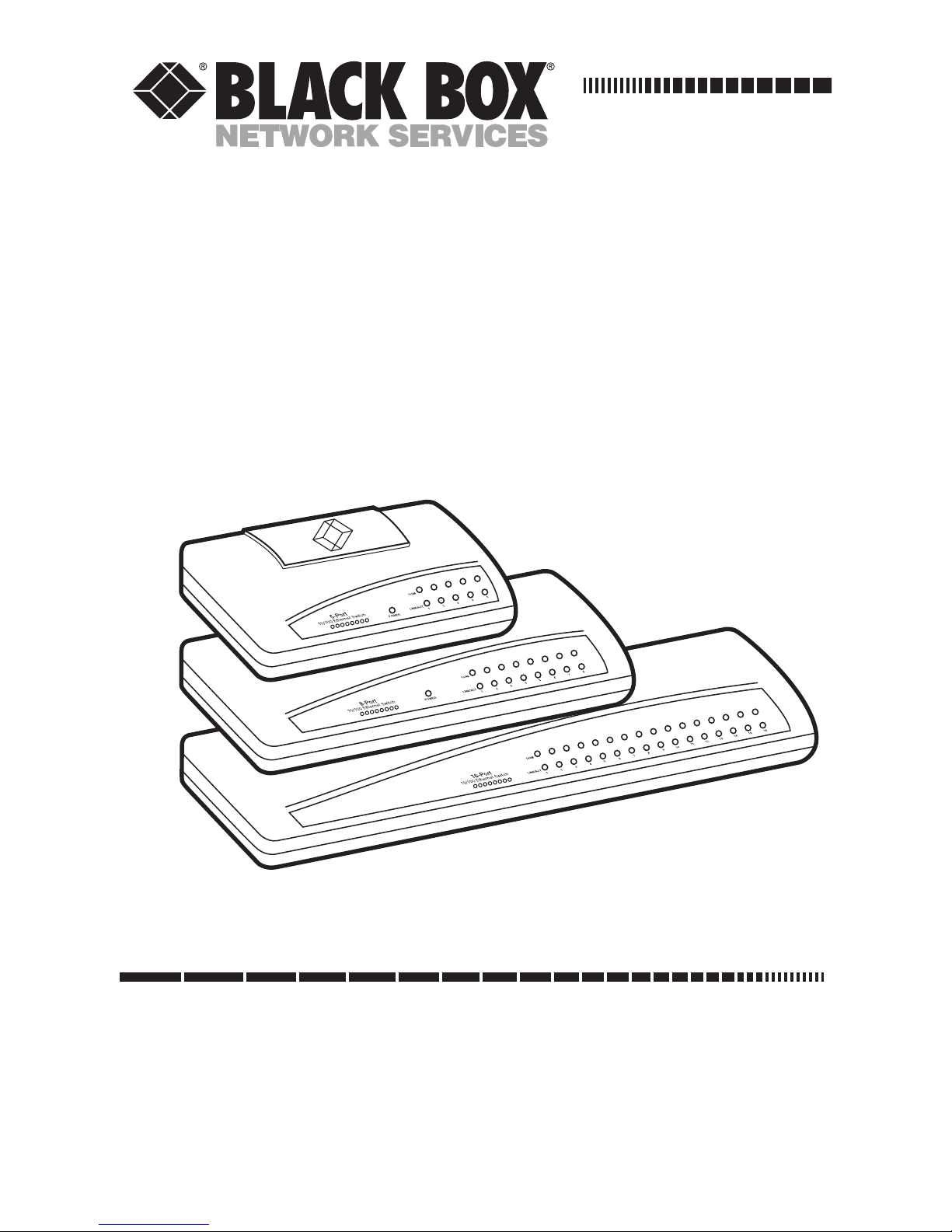
LB8505A
LB8508A
LB8516A
5-Port 10/100 Ethernet Switch
8-Port 10/100 Ethernet Switch
16-Port 10/100 Ethernet Switch
CUSTOMER SUPPORT INFORMATION
Order toll-free in the U.S.: Call 877-877-BBOX (outside U.S. call 724-746-5500)
FREE technical support 24 hours a day, 7 days a week: Call 724-746-5500 or fax 724-746-0746
Mailing address: Black Box Corporation, 1000 Park Drive, Lawrence, PA 15055-1018
Web site: www.blackbox.com • E-mail: info@blackbox.com
Page 2

Page 3

1
FCC AND IC RFI STATEMENTS
FEDERAL COMMUNICATIONS COMMISSION
and INDUSTRY CANADA
RADIO FREQUENCY INTERFERENCE STATEMENTS
Class B Digital Device. This equipment has been
tested and found to comply with the limits for a
Class B computing device pursuant to Part 15 of
the FCC Rules. These limits are designed to
provide reasonable protection against harmful
interference in a residential installation.
However, there is no guarantee that
interference will not occur in a particular
installation. This equipment generates, uses,
and can radiate radio frequency energy, and, if
not installed and used in accordance with the
instructions, may cause harmful interference to
radio communications. If this equipment does
cause harmful interference to radio or
telephone reception, which can be determined
by turning the equipment off and on, the user
is encouraged to try to correct the interference
by one of the following measures:
• Reorient or relocate the receiving
antenna.
Page 4

2
10/100 ETHERNET SWITCHES
• Increase the separation between the
equipment and receiver.
• Connect the equipment into an outlet on
a circuit different from that to which the
receiver is connected.
• Consult an experienced radio/TV
technician for help.
CAUTION
Changes or modifications not expressly
approved by the party responsible for
compliance could void the user’s authority to
operate the equipment.
To meet FCC requirements, shielded cables
and power cords are required to connect this
device to a personal computer or other Class B
certified device.
This digital apparatus does not exceed the Class B
limits for radio noise emission from digital apparatus
set out in the Radio Interference Regulation of
Industry Canada.
Le présent appareil numérique n’émet pas de bruits
radioélectriques dépassant les limites applicables aux
appareils numériques de classe B prescrites dans le
Règlement sur le brouillage radioélectrique publié par
Industrie Canada.
Page 5

3
NOM STATEMENT
Normas Oficiales Mexicanas (NOM)
Electrical Safety Statement
INSTRUCCIONES DE SEGURIDAD
1. Todas las instrucciones de seguridad y
operación deberán ser leídas antes de
que el aparato eléctrico sea operado.
2. Las instrucciones de seguridad y
operación deberán ser guardadas para
referencia futura.
3. Todas las advertencias en el aparato
eléctrico y en sus instrucciones de
operación deben ser respetadas.
4. Todas las instrucciones de operación y
uso deben ser seguidas.
5. El aparato eléctrico no deberá ser usado
cerca del agua—por ejemplo, cerca de la
tina de baño, lavabo, sótano mojado o
cerca de una alberca, etc..
6. El aparato eléctrico debe ser usado
únicamente con carritos o pedestales que
sean recomendados por el fabricante.
Page 6

4
10/100 ETHERNET SWITCHES
7. El aparato eléctrico debe ser montado a
la pared o al techo sólo como sea
recomendado por el fabricante.
8. Servicio—El usuario no debe intentar dar
servicio al equipo eléctrico más allá a lo
descrito en las instrucciones de
operación. Todo otro servicio deberá ser
referido a personal de servicio calificado.
9. El aparato eléctrico debe ser situado de
tal manera que su posición no interfiera
su uso. La colocación del aparato
eléctrico sobre una cama, sofá, alfombra
o superficie similar puede bloquea la
ventilación, no se debe colocar en
libreros o gabinetes que impidan el flujo
de aire por los orificios de ventilación.
10. El equipo eléctrico deber ser situado
fuera del alcance de fuentes de calor
como radiadores, registros de calor,
estufas u otros aparatos (incluyendo
amplificadores) que producen calor.
11. El aparato eléctrico deberá ser
connectado a una fuente de poder sólo
del tipo descrito en el instructivo de
operación, o como se indique en el
aparato.
Page 7

5
NOM STATEMENT
12. Precaución debe ser tomada de tal
manera que la tierra fisica y la
polarización del equipo no sea eliminada.
13. Los cables de la fuente de poder deben
ser guiados de tal manera que no sean
pisados ni pellizcados por objetos
colocados sobre o contra ellos, poniendo
particular atención a los contactos y
receptáculos donde salen del aparato.
14. El equipo eléctrico debe ser limpiado
únicamente de acuerdo a las
recomendaciones del fabricante.
15. En caso de existir, una antena externa
deberá ser localizada lejos de las lineas de
energia.
16. El cable de corriente deberá ser
desconectado del cuando el equipo no
sea usado por un largo periodo de
tiempo.
17. Cuidado debe ser tomado de tal manera
que objectos liquidos no sean derramados
sobre la cubierta u orificios de
ventilación.
Page 8

6
10/100 ETHERNET SWITCHES
18. Servicio por personal calificado deberá
ser provisto cuando:
A: El cable de poder o el contacto ha sido
dañado; u
B: Objectos han caído o líquido ha sido
derramado dentro del aparato; o
C: El aparato ha sido expuesto a la lluvia; o
D: El aparato parece no operar
normalmente o muestra un cambio en su
desempeño; o
E: El aparato ha sido tirado o su cubierta ha
sido dañada.
Page 9

7
CE NOTICE
EUROPEAN UNION DECLARATION OF
CONFORMITY
This equipment complies with the
requirements of the European EMC Directive
89/336/EEC.
Page 10

8
10/100 ETHERNET SWITCHES
TRADEMARKS USED IN THIS MANUAL
Any trademarks mentioned in this manual are
acknowledged to be the property of the trademark
owners.
Page 11

9
CONTENTS
Contents
Chapter Page
1. Specifications . . . . . . . . . . . . . . . . . . . . . 10
2. Introduction . . . . . . . . . . . . . . . . . . . . . . 12
2.1 Description . . . . . . . . . . . . . . . . . . . . 12
2.2 Features. . . . . . . . . . . . . . . . . . . . . . . 18
2.3 What the Package Includes . . . . . . . 18
3. Installation . . . . . . . . . . . . . . . . . . . . . . . 19
3.1 Choosing the Proper
Environment . . . . . . . . . . . . . . . . . . 19
3.2 Connecting to Network Devices . . . 19
3.3 Connecting the Power . . . . . . . . . . . 20
4. Troubleshooting. . . . . . . . . . . . . . . . . . . 22
4.1 Problems/Solutions . . . . . . . . . . . . . 22
4.2 Calling Black Box . . . . . . . . . . . . . . . 23
4.3 Shipping and Packaging . . . . . . . . . 24
Page 12

10
10/100 ETHERNET SWITCHES
1. Specifications
Buffer: LB8505A: 128 KB;
LB8508A: 256 KB;
LB8516A: 512 KB
Filtering and Forwarding Rate: 148,800 pps
MAC Address Table: LB8505A: 1K;
LB8508A, LB8516A: 8K
Standards: IEEE 802.3 10BASE-T, IEEE 802.3u
100BASE-TX
Switching Architecture: Store and forward
Connectors: LB8505A: (5) RJ-45;
LB8508A: (8) RJ-45; LB8516A: (16) RJ-45
Indicators: All models: (1) Power LED;
LB8505A: (10) LEDs: Per port:
(1) Link/Activity, (1) 100 M;
LB8508A: (16) LEDs: Per port:
(1) Link/Activity, (1) 100 M;
LB8516A: (32) LEDs: Per port:
(1) Link/Activity, (1) 100 M
Page 13

11
CHAPTER 1: Specifications
Power: 120 VAC, 60 Hz, external power supply;
Input Power: LB8505A, LB8508A: 12 VDC,
0.5 amp, LB8516A: 12 VDC, 1 amp
Size: LB8505A: 1.3"H x 5"W x 3.3"D
(3.3 x 12.7 x 8.4 cm);
LB8508A: 1.4"H x 7.4"W x 3.9"D
(3.6 x 18.8 x 9.9 cm);
LB8516A: 1.4"H x 11.4"W x 3.9"D
(3.6 x 29 x 9.9 cm)
Weight: LB8505A: 0.4 lb. (0.2 kg);
LB8508A: 0.6 lb. (0.3 kg);
LB8516A: 1.1 lb. (0.5 kg)
Page 14

12
10/100 ETHERNET SWITCHES
2. Introduction
2.1 Description
The 10/100 Ethernet Switch provides extra Fast
Ethernet ports to segment network traffic,
extend Fast Ethernet connection distance, and
convert data packets between different
transmission speeds. All of the UTP ports on
the switch support MDI/MDI-X, so you can
connect either a straight-through or crossover
cable to another switch or hub.
Three models are available. The LB8505A has 5
shielded, auto-negotiating 10BASE-T/100BASETX RJ-45 ports. The LB8508A has 8 RJ-45 ports,
and the LB8516A has 16. All of the switch’s
UTP ports support full and half-duplex modes.
When running in half-duplex mode, ports
configured as 10BASE-T provide 10 Mbps of
bandwidth; ports configured as 100BASE-TX
give you 100 Mbps of bandwidth. In full duplex
mode, this bandwidth doubles. Ports
configured as 10BASE-T give you 20 Mbps of
bandwidth; ports configured as 100BASE-TX
provide 200 Mbps of bandwidth. The switch is
Page 15

13
CHAPTER 2: Introduction
typically used to segment network traffic. This
can improve the network performance by
increasing the total bandwidth, as illustrated in
Figure 2-1.
Figure 2-1. Increasing network bandwidth.
The switch uses store-and-forward switching
architecture. It filters and forwards data after
the complete data packet is received,
examined, and determined to be free of errors.
Each individual port has (1) 100M LED and
(1) Link/Activity LED. This compact switch fits
neatly on a desktop, mounted on a wall, or
mounted on the side of a desk.
200 Mbps
Switch or
Hub
Switch or
Hub
Switch or
Hub
Switch or
Hub
100
Mbps
100
Mbps
100
Mbps
100
Mbps
Page 16

14
10/100 ETHERNET SWITCHES
The front and back panels of the 5-Port 10/100
Ethernet Switch are shown in Figure 2-2.
Figure 2-2. 10/100 Ethernet Switch, 5-Port.
LED panel
RJ-45
connectors
Power
connector
Power LED
100M LEDs
Link/
Activity
LEDs
Page 17

15
CHAPTER 2: Introduction
The front and back panels of the 8-Port 10/100
Ethernet Switch are shown in Figure 2-3.
Figure 2-3. 10/100 Ethernet Switch, 8-Port.
LED panel
RJ-45
connectors
Power
connector
Power LED
100M LEDs
Link/
Activity
LEDs
Page 18

16
10/100 ETHERNET SWITCHES
The front and back panels of the 16-Port
10/100 Ethernet Switch are shown in
Figure 2-4.
Figure 2-4. 10/100 Ethernet Switch, 16-Port.
LED panel
RJ-45
connectors
Power
connector
Power LED
100M LEDs
Link/
Activity
LEDs
Page 19

17
CHAPTER 2: Introduction
Table 2-1 describes the LEDs on the 10/100
Ethernet Switches shown in Figures 2-2 through
2-4.
Table 2-1. LED descriptions.
LED Color Status Description
Power Green On Power is supplied.
Off No power.
LNK/ACT Green On A valid link is
(Link/ established.
Activity)
Flashing Data packets received.
Off No link is established.
SPEED Yellow On Port is running at
(100M) 100 Mbps.
Off Port is running at 10 Mbps.
Page 20

18
10/100 ETHERNET SWITCHES
2.2 Features
• Complies with IEEE 802.3 10BASE-T
Ethernet and 100BASE-TX Fast Ethernet
standards.
• Simple and economical way to bridge a
10BASE-T network and a 100BASE-TX
network.
• Easily connect Fast Ethernet hubs or
segments.
2.3 What the Package Includes
Your package should include the following
items.
• (1) 10/100 Ethernet Switch
• (1) External power supply
• This users’ manual
If anything is missing or damaged, please
contact Black Box at 724-746-5500.
Page 21

19
CHAPTER 3: Installation
3. Installation
3.1 Choosing the Proper Environment
Install and operate the switch within the limits
of the specified temperature and humidity
tolerance (see Chapter 1). Don’t place objects
on top of the switch or obstruct the switch’s
side vents. Also, don’t position the switch near
any heating source such as a heater, radiator, or
in direct exposure to the sun. Protect the switch
from water and moisture. If necessary, use a
dehumidifier to reduce humidity.
3.2 Connecting to Network Devices
The RJ-45 ports on the switch support AutoMDI/MDI-X, so you can use either straightthrough or crossover cable to connect the
switch to a workstation or hub.
Connect one end of the network cable to the
RJ-45 port on the switch’s rear panel. Connect
the other end of the cable to the network
device’s RJ-45 port. Repeat this procedure until
you’ve connected all of the switch’s RJ-45 ports.
Page 22

20
10/100 ETHERNET SWITCHES
The UTP network cables must comply with
EIA/TIA-568 specifications and the Category 5
standard for 100 Mbps data transmission. The
maximum length of UTP cable allowed
between the switch and a connected device is
100 m (328 ft.). Once the network cable is
connected to the 10/100 Ethernet Switch and
the networking device and the attached device
is powered on, the green LNK/ACT LED
should light.
3.3 Connecting the Power
Connect the output end of the power adapter
to the power connector on the rear panel of
the switch. Connect the power adapter to a
power outlet. The green Power LED on the
front panel should light.
Page 23

21
CHAPTER 3: Installation
Figure 3-1. Connecting the power adapter.
External power
adapter
AC
power
DC power
Page 24

22
10/100 ETHERNET SWITCHES
4. Troubleshooting
4.1 Problems/Solutions
Problem: The Power LED is not lit.
Solution: Is the power cord properly connected
to the external power adapter and the power
outlet? Make sure the DC power jack is firmly
plugged into the power socket of the switch.
Problem: The Link/Activity LED is not lit when
connected to the 100-Mbps device.
Solution:
1. Is the network device’s power switch
attached to the switch? Is it turned on?
2. Check the network cable. Is it properly
connected to the switch and the network
device?
3. Make sure that the network UTP cables
comply with EIA/TIA 568 and Category 5
specifications.
Page 25

23
CHAPTER 4: Troubleshooting
4.2 Calling Black Box
If you determine that your 10/100 Ethernet
Switch is malfunctioning, do not attempt to
alter or repair the unit. It contains no userserviceable parts. Contact Black Box at 724-746-
5500.
Before you do, make a record of the history of
the problem. We will be able to provide more
efficient and accurate assistance if you have a
complete description, including:
• the nature and duration of the problem.
• when the problem occurs.
• the components involved in the problem.
• any particular application that, when
used, appears to create the problem or
make it worse.
Page 26

24
10/100 ETHERNET SWITCHES
4.3 Shipping and Packaging
If you need to transport or ship your 10/100
Ethernet Switch:
• Package it carefully. We recommend that
you use the original container.
• If you are shipping the 10/100 Ethernet
Switch for repair, make sure you include
everything that came in the original
package. Before you ship, contact Black
Box to get a Return Authorization (RA)
number.
Page 27

1000 Park Drive • Lawrence, PA 15055-1018 • 724-746-5500 • Fax 724-746-0746
© Copyright 2002. Black Box Corporation. All rights reserved.
 Loading...