

Page 1
CUSTOMER
SUPPORT
INFORMATION
Order toll-free in the U.S.: Call 877-877-BBOX (outside U.S. call 724-746-5500)
FREE technical support 24 hours a day, 7 days a week: Call 724-746-5500 or fax 724-746-0746
Mailing address: Black Box Corporation, 1000 Park Drive, Lawrence, PA 15055-1018
Web site: www.blackbox.com • E-mail: info@blackbox.com
AUGUST 2001
LB5953A
LB5954A
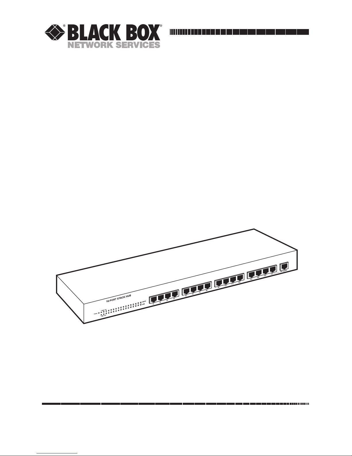
16-Port Stack Hub
24-Port Stack Hub
Page 2

1
FCC AND IC RFI STATEMENTS/CE NOTICE
FEDERAL COMMUNICATIONS COMMISSION
AND
INDUSTRY CANADA
RADIO FREQUENCY INTERFERENCE STATEMENTS
This equipment generates, uses, and can radiate radio frequency energy and if not
installed and used properly, that is, in strict accordance with the manufacturer’s
instructions, may cause interference to radio communication. It has been tested
and found to comply with the limits for a Class A computing device in accordance
with the specifications in Subpart J of Part 15 of FCC rules, which are designed to
provide reasonable protection against such interference when the equipment is
operated in a commercial environment. Operation of this equipment in a
residential area is likely to cause interference, in which case the user at his own
expense will be required to take whatever measures may be necessary to correct
the interference.
Changes or modifications not expressly approved by the party responsible
for compliance could void the user’s authority to operate the equipment.
This digital apparatus does not exceed the Class A limits for radio noise emission from
digital apparatus set out in the Radio Interference Regulation of Industry Canada.
Le présent appareil numérique n’émet pas de bruits radioélectriques dépassant les limites
applicables aux appareils numériques de la classe A prescrites dans le Règlement sur le
brouillage radioélectrique publié par Industrie Canada.
EUROPEAN UNION DECLARATION OF CONFORMITY
This equipment complies with the requirements of the European EMC Directive
89/336/EEC.
Page 3

2
16- AND 24-PORT STACK HUBS
NORMAS OFICIALES MEXICANAS (NOM)
ELECTRICAL SAFETY STATEMENT
INSTRUCCIONES DE SEGURIDAD
1. Todas las instrucciones de seguridad y operación deberán ser leídas antes de
que el aparato eléctrico sea operado.
2. Las instrucciones de seguridad y operación deberán ser guardadas para
referencia futura.
3. Todas las advertencias en el aparato eléctrico y en sus instrucciones de
operación deben ser respetadas.
4. Todas las instrucciones de operación y uso deben ser seguidas.
5. El aparato eléctrico no deberá ser usado cerca del agua—por ejemplo, cerca
de la tina de baño, lavabo, sótano mojado o cerca de una alberca, etc..
6. El aparato eléctrico debe ser usado únicamente con carritos o pedestales que
sean recomendados por el fabricante.
7. El aparato eléctrico debe ser montado a la pared o al techo sólo como sea
recomendado por el fabricante.
8. Servicio—El usuario no debe intentar dar servicio al equipo eléctrico más allá
a lo descrito en las instrucciones de operación. Todo otro servicio deberá ser
referido a personal de servicio calificado.
9. El aparato eléctrico debe ser situado de tal manera que su posición no
interfiera su uso. La colocación del aparato eléctrico sobre una cama, sofá,
alfombra o superficie similar puede bloquea la ventilación, no se debe colocar
en libreros o gabinetes que impidan el flujo de aire por los orificios de
ventilación.
10. El equipo eléctrico deber ser situado fuera del alcance de fuentes de calor
como radiadores, registros de calor, estufas u otros aparatos (incluyendo
amplificadores) que producen calor.
Page 4

3
NOM STATEMENT
11. El aparato eléctrico deberá ser connectado a una fuente de poder sólo del
tipo descrito en el instructivo de operación, o como se indique en el aparato.
12. Precaución debe ser tomada de tal manera que la tierra fisica y la polarización
del equipo no sea eliminada.
13. Los cables de la fuente de poder deben ser guiados de tal manera que no
sean pisados ni pellizcados por objetos colocados sobre o contra ellos,
poniendo particular atención a los contactos y receptáculos donde salen del
aparato.
14. El equipo eléctrico debe ser limpiado únicamente de acuerdo a las
recomendaciones del fabricante.
15. En caso de existir, una antena externa deberá ser localizada lejos de las lineas
de energia.
16. El cable de corriente deberá ser desconectado del cuando el equipo no sea
usado por un largo periodo de tiempo.
17. Cuidado debe ser tomado de tal manera que objectos liquidos no sean
derramados sobre la cubierta u orificios de ventilación.
18. Servicio por personal calificado deberá ser provisto cuando:
A: El cable de poder o el contacto ha sido dañado; u
B: Objectos han caído o líquido ha sido derramado dentro del aparato; o
C: El aparato ha sido expuesto a la lluvia; o
D: El aparato parece no operar normalmente o muestra un cambio en su
desempeño; o
E: El aparato ha sido tirado o su cubierta ha sido dañada.
Page 5

4
16- AND 24-PORT STACK HUBS
TRADEMARKS USED IN THIS MANUAL
Any trademarks mentioned in this manual are acknowledged to be the property of the
trademark owners.
Page 6

5
CONTENTS
Contents
Chapter Page
1. Specifications . . . . . . . . . . . . . . . . . . . . . . . . . . . . . . . . . . . . . . . . . . . . . . . . 6
1.1 General . . . . . . . . . . . . . . . . . . . . . . . . . . . . . . . . . . . . . . . . . . . . . . . . . . 6
1.2 Hub-to-Hub Cascading . . . . . . . . . . . . . . . . . . . . . . . . . . . . . . . . . . . . . 6
1.3 LED Indicators . . . . . . . . . . . . . . . . . . . . . . . . . . . . . . . . . . . . . . . . . . . . 6
1.4 Environmental and Physical . . . . . . . . . . . . . . . . . . . . . . . . . . . . . . . . . 7
2. Introduction . . . . . . . . . . . . . . . . . . . . . . . . . . . . . . . . . . . . . . . . . . . . . . . . . 8
2.1 Overview . . . . . . . . . . . . . . . . . . . . . . . . . . . . . . . . . . . . . . . . . . . . . . . . . 8
2.2 Features. . . . . . . . . . . . . . . . . . . . . . . . . . . . . . . . . . . . . . . . . . . . . . . . . . 8
2.3 What the Package Includes . . . . . . . . . . . . . . . . . . . . . . . . . . . . . . . . . . 9
3. Setup . . . . . . . . . . . . . . . . . . . . . . . . . . . . . . . . . . . . . . . . . . . . . . . . . . . . . . 10
3.1 Identifying External Components . . . . . . . . . . . . . . . . . . . . . . . . . . . 10
3.1.1 Front Panel. . . . . . . . . . . . . . . . . . . . . . . . . . . . . . . . . . . . . . . . . . . 10
3.1.2 Rear Panel . . . . . . . . . . . . . . . . . . . . . . . . . . . . . . . . . . . . . . . . . . . 11
3.2 Installing the Hub . . . . . . . . . . . . . . . . . . . . . . . . . . . . . . . . . . . . . . . . 11
3.2.1 Installation . . . . . . . . . . . . . . . . . . . . . . . . . . . . . . . . . . . . . . . . . . . 11
3.2.2 Rack Mounting . . . . . . . . . . . . . . . . . . . . . . . . . . . . . . . . . . . . . . . 12
4. Indicators . . . . . . . . . . . . . . . . . . . . . . . . . . . . . . . . . . . . . . . . . . . . . . . . . . 13
4.1 Hub State Indicators . . . . . . . . . . . . . . . . . . . . . . . . . . . . . . . . . . . . . . 13
4.2 Port State Indicators. . . . . . . . . . . . . . . . . . . . . . . . . . . . . . . . . . . . . . . 13
5. Making Connections . . . . . . . . . . . . . . . . . . . . . . . . . . . . . . . . . . . . . . . . . 14
5.1 Hub Cascading/Building a Stack . . . . . . . . . . . . . . . . . . . . . . . . . . . . 14
5.2 Connectivity Rules . . . . . . . . . . . . . . . . . . . . . . . . . . . . . . . . . . . . . . . . 15
5.3 Hub to End-Station Connection . . . . . . . . . . . . . . . . . . . . . . . . . . . . . 15
5.4 Hub-to-Hub Uplink . . . . . . . . . . . . . . . . . . . . . . . . . . . . . . . . . . . . . . . 16
6. Cables and Connectors . . . . . . . . . . . . . . . . . . . . . . . . . . . . . . . . . . . . . . . 17
6.1 100BASE-TX Ethernet Cable and Connectors . . . . . . . . . . . . . . . . . 17
6.2 Crossover Cables. . . . . . . . . . . . . . . . . . . . . . . . . . . . . . . . . . . . . . . . . . 18
Page 7

6
16- AND 24-PORT STACK HUBS
1. Specifications
1.1 General
Standards: IEEE 802.3 10BASE-T Ethernet; IEEE 802.3u 100BASE-TX Fast
Ethernet
Topology: Star
Protocol: CSMA/CD
Network Data Transfer Rate: Ethernet:10 Mbps; Fast Ethernet: 100 Mbps
Number of Ports: LB5953A: (16) MDI-X, (1) MDI-II uplink, (1) expansion slot;
LB5954A: (24) MDI-X, (1) MDI-II uplink, (1) expansion slot
Network Media: Ethernet: Category 3 or better UTP; Fast Ethernet: Category 5
UTP/STP, 100-ohm twisted-pair
1.2 Hub-to-Hub Cascading
Number of Daisychained Hubs: Maximum of 4 hubs per stack
Daisychain Port: DB25 connector
Daisychain Cable: DB25 cable (included)
1.3 LED Indicators
Per Hub: (1) power, (1) 100-Mbps activity, (1) 10-Mbps collision, (1) 100-Mbps
collision, (1) hub activity;
Per port: (1) 10-Mbps Link/RX, (1) 100-Mbps Link/RX
Page 8

7
CHAPTER 1: Specifications
1.4 Environmental and Physical
Temperature: Operating: -14 to +104°F (-25 to +40°C); Storage: -4 to +158°F
(-20 to +70°C)
Humidity: 10 to 90%, noncondensing
Emissions: FCC Class A, CE, VCCI-I
Safety: cUL, TUV
Power Supply: 100 to 240 VAC, 50 to 60 Hz, autosensing, internal universal power
supply
Power Consumption: 40 watts (max.)
Size: 1.7"H x 17.3"W x 7.9"D (4.3 x 43.9 x 20.1 cm), 19-inch rack-mountable
Weight: LB5953A: 9 lb. (4.1 kg); LB5954A: 10 lb. (4.5 kg)
Page 9

8
16- AND 24-PORT STACK HUBS
2. Introduction
2.1 Overview
The 16- and 24-Port Stack Hubs allow easy migration and integration between
10-Mbps Ethernet and 100-Mbps Fast Ethernet while providing manageability and
flexibility in cable connections.
The Hub can operate with either IEEE 802.3 10BASE-T connections (twisted-pair
Ethernet operating at 10 Mbps) or IEEE 802.3u 100BASE-TX connections (twistedpair Fast Ethernet operating at 100 Mbps). All of the twisted-pair ports support
10-/100-Mbps auto-negotiation, allowing the hub to automatically detect the speed
of a network connection. That means you can connect all of your Ethernet and
Fast Ethernet hosts to any hub in the series without any rewiring required when a
host is upgraded from 10 Mbps to 100 Mbps.
The Hubs can be stacked with up to four hubs in a stack. A stack of four 24-port
hubs yields 96 Ethernet/Fast Ethernet ports. The Hub operates as a Class II Fast
Ethernet repeater, allowing it to be linked to another Class II Fast Ethernet stack in
the same collision domain.
In the basic configuration, the 10-Mbps and 100-Mbps segments are separate but
can intercommunicate. Each unit has a built-in switch, so it can intercommunicate
and stack up to four units.
2.2 Features
• Compatible with the IEEE 802.3 10BASE-T Ethernet and 802.3u 100BASE-TX
Fast Ethernet industry standards for interoperability with other Ethernet/Fast
Ethernet network devices.
• Ethernet connections support Category 3 or better twisted-pair cables.
NOTE
In mixed environments, you must use Category 5 or above twisted-pair
cables.
• Fast Ethernet connections support both shielded twisted-pair and Category 5
unshielded twisted-pair cables.
• Fast Ethernet connections support a maximum distance of 100 meters (328 ft.)
from end-station to Hub, and a total network diameter of 205 meters (673 ft.).
Page 10

9
CHAPTER 2: Introduction
• (16) or (24) 10-/100-Mbps RJ-45 ports for connecting stations to the network.
• The Hubs, with their built-in switch function, automatically transfer packets
between 10-Mbps Ethernet and 100-Mbps Fast Ethernet connections, allowing
communication between end nodes operating at different speeds.
• LED indicators for power, 100-Mbps activity, 10-Mbps collision, 100-Mbps
collision, hub activity, and Link/RX.
• Two proprietary daisychain ports for cascading up to four hubs to form one
logical hub.
• Uplink jack for easy linking of two hubs to further expand the network.
• Standard-size (19", 1U height), rack mountable.
• The total bandwidth of each stack is up to 140 Mbps. That includes one
100-Mbps segment and four 10-Mbps segments (if the stack consists of the
maximum four units).
2.3 What the Package Includes
• (1) 16- or 24-Port 10-/100-Mbps dual-speed stackable hub.
• (1) AC power cord, suitable for your area’s electrical power connections.
• (1) Daisychain cable.
• (4) Rubber feet to be used for shock cushioning.
• Screws and two mounting brackets.
• This users’ manual.
If anything is missing or damaged, please call Black Box at 724-746-5500.
Page 11

10
16- AND 24-PORT STACK HUBS
3. Setup
3.1 Identifying External Components
This section identifies all the major external components of the hub. Both the
front and rear panels are shown, followed by a description of each panel feature.
The indicators are described in detail in Chapter 4.
3.1.1 F
RONTPANEL
Figure 3-1. Front panel.
• LED Indicator Panel: See Chapter 4 for detailed information about each of the
Hub’s LED indicators.
• Twisted-Pair Ports: Use any of these ports to connect stations to the hub. The
ports are MDI-X ports, which means you can use ordinary straight-through
twisted-pair cable to connect the Hub to PCs, workstations, or servers through
these ports. If you need to connect to another device with MDI-X ports, such
as another hub or Ethernet Switch, you should use a crossover cable or
connect using the Uplink port (described below). For more information about
crossover connection, see Section 6.2.
• Uplink Ports: The Uplink port is a MDI port, which means you can connect
the Hub (or Hub stack) to another device with MDI-X ports using an ordinary
straight-through cable, making a crossover cable unnecessary.
In the 16-port model, port 16 and the Uplink port are really the same port,
except that their pinouts are different. Do not use both Port 16 and the Uplink
port at the same time.
In the 24-port model, port 12 and the Uplink port are really the same port,
except that their pinouts are different. Do not use both Port 12 and the Uplink
port at the same time.
Page 12

11
CHAPTER 3: Setup
3.1.2 R
EARPANEL
Figure 3-2. Rear panel.
• Module Slot: Reserved for future use.
• Daisychain IN Port: When cascading a set of the Hubs, this port should be
connected to the daisychain OUT port of the previous hub in the stack
(usually placed immediately above it). You can create a cascade of four hubs
this way. The first and last hubs in the stack use only one of the daisychain
ports, while the others use both.
• Daisychain OUT Port: Works in conjunction with the Daisychain IN Port (see
above). Connect this port to the Daisychain IN Port of the next hub in the
stack (usually placed immediately below it) using the included daisychain
cable.
• AC Power Connector: For the AC power cord.
3.2 Installing the Hub
3.2.1 I
NSTALLATION
The site where you install the hub stack may greatly affect its performance. When
installing, consider the following:
• Install the Hub stack in a fairly cool and dry place. See Chapter 1 for the
acceptable temperature and humidity operating ranges.
• Install the Hub stack in a site free from strong electromagnetic field
generators (such as motors), vibration, dust, and direct exposure to sunlight.
• Leave at least 3.9" (9.9 cm) of space at the front and rear of the Hub for
adequate ventilation.
Power
connector
Module slot
Daisychain
ports
Page 13

12
16- AND 24-PORT STACK HUBS
• Install the Hub on a sturdy, level surface that can support its weight, or in an
EIA standard-size equipment rack. For information on rack installation, see
Section 3.2.2.
When installing the Hub stack on a level surface, attach the rubber feet to the
bottom of each device. The rubber feet cushion the Hub and protect the Hub case
from scratches.
3.2.2 R
ACKMOUNTING
The Hub can be mounted in an EIA standard-size, 19-inch rack (48.3-cm), which
can be placed in a wiring closet with other equipment. Attach the mounting
brackets at the Hub’s front panel (one on each side), and secure them with the
provided screws.
Figure 3-3. Attaching the mounting brackets.
Then use screws provided with the equipment rack to mount each hub in the rack.
Figure 3-4. Installing the screws.
Page 14

13
CHAPTER 4: Indicators
4. Indicators
Before connecting network devices to the hub, take a few minutes to read this
chapter and familiarize yourself with the front-panel LED indicators.
4.1 Hub State Indicators
• Power Indicator: This indicator lights green when the Hub is receiving power;
otherwise, it is off.
• 10M Collision, 100M Collision: These indicators indicate data collisions on the
respective 10-Mbps Ethernet or 100-Mbps Fast Ethernet segments of the Hub.
Whenever a collision is detected, the respective COL indicator will briefly blink
amber. (Although several hubs can be stacked or linked together, the stacking
capability of the Hubs connects the 100-Mbps collision domain only; that is
why the stack has a capacity of 140 Mbps total bandwidth—the common
100BASE-TX domain, plus one 10BASE-T domain for each hub in the stack.
Therefore, a collision on a 10BASE-T segment will not be shown on the other
hubs in the stack, but a collision in the 100BASE-TX domain will show on each
hub in the stack.)
• FX Link: Reserved for future use.
4.2 Port State Indicators
Status indicators exist for each of the twisted-pair ports on the Hub. Each port’s
LED status indicators report the port is working on 10BASE-T mode or
100BASE–TX mode and indicator link or receive status.
The following describes each indicator and the meaning of each condition:
• Link/Rx: This indicator lights green when the port is connected to a 10-Mbps
Ethernet or 100-Mbps station. If the station to which the hub is connected is
powered off, or if there is a problem with the link, the LED will remain off.
The indicator blinks green when the data will be received to all other
connected ports.
• 100M: This indicator lights green when the port is connected to a 100-Mbps
station; otherwise, the LED remains off. This means the port is connected to a
10-Mbps Ethernet station.
Page 15

14
16- AND 24-PORT STACK HUBS
5. Making Connections
This chapter discusses a) how to make connections to the Hub’s twisted-pair,
b) cascading hubs to create a stack, and c) linking with other hubs (or hub stacks).
5.1 Hub Cascading/Building a Stack
You can stack up to four Hubs using the daisychain ports to form one logical hub.
In this configuration, the interconnected hubs constitute a single logical unit,
providing a maximum of 96 twisted-pair ports.
Use the provided daisychain cable to connect the daisychain OUT port on the rear
panel of one Hub to the Daisychain IN port on the Hub below it, as shown in
Figure 5-1. Repeat this procedure for each hub to be included in the stack.
Figure 5-1. Hub cascading.
Hubs should not be added to or removed from the stack while the power is on to
any Hub in the stack. Always turn OFF power to the entire stack before adding or
removing hubs.
Page 16

15
CHAPTER 5: Making Connections
5.2 Connectivity Rules
Ethernet (10-Mbps) networks have the following connectivity rules:
• The maximum length of a twisted-pair cable segment is 100 meters (328 ft.).
Cabling should be Category 3 or better.
• Between any two end-stations in a collision domain, there may be up to five
cable segments and four intermediate repeaters (hubs, hub stacks, or other
repeaters). Use 10-Mbps Ethernet repeaters to connect in your 10-Mbps
network segments to avoid the limitations of Fast Ethernet. Because if you
haven’t used pure 10-Mbps Ethernet repeaters in these network segments,
then these segments must operate under the rules of Fast Ethernet Standards
in those Dual-Speed Ethernet products that you use now.
• If there is a path between any two end-stations containing five segments and
four repeaters, then at least two of the cable segments must be point-to-point
link segments (for example, 10BASE-T or 10BASE-FL), while the remaining
segments may be populated (mixing) segments (for example, 10BASE2 or
10BASE5).
Fast Ethernet (100-Mbps) networks have the following connectivity rules:
• The maximum length of a twisted-pair segment (that is, the distance between a
port in the hub to a single-address network device such as a PC, server, or
Ethernet switch) is 100 meters (328 ft.). Cabling and other wiring should be
certified as Category 5 UTP or shielded twisted-pair (STP).
• The maximum diameter in a collision domain is about 205 meters (673 ft.)
using two Class II hubs (or hub stacks).
• Between any two end-stations in a collision domain, there may be up to three
cable segments and two Class II hubs or hub stacks.
5.3 Hub to End-Station Connection
After installing the hub properly, it can support up to 24 ports or 16 ports of endstation connections. Fast Ethernet connections require either a Category 5 or
better UTP or STP cable. These cables can be up to 100 meters (328 ft.) long.
Each Ethernet connection requires a Category 3 or better UTP cable. We
recommend using Category 5 or better cabling for all connections in order to
make it easier to transition all stations to 100 Mbps.
Page 17

16
16- AND 24-PORT STACK HUBS
You can connect any combination of PCs, servers, and other single-address network
devices to the twisted-pair ports using straight-through twisted-pair cables. These
cables should not be crossed over. The following figure illustrates the pin
assignments for a straight-through cable:
Figure 5-2. Straight-through cable pinning.
When connecting a PC or a server, the system being connected should have an
Ethernet or Fast Ethernet network interface card with a twisted-pair port.
5.4 Hub-to-Hub Uplink
You can link two Hubs or Hub stacks to each other using the Uplink port. Linking
using one ordinary twisted-pair port and the Uplink port requires an ordinary
straight-through twisted-pair cable.
When connecting two hubs or hub stacks in this fashion, the maximum distance
between any two end-stations in a collision domain is 205 meters (673 ft.).
However, the true measure of whether your network will operate correctly in a
collision domain while using a mix of physical media and repeaters is the bit time
delay of the physical media and repeaters. If the bit time delay exceeds 512 bit times
in a collision domain, the network will not operate properly, regardless of the
physical distances. For assistance in designing your network to accommodate the
maximum diameter it can achieve under individual conditions, please contact
Black Box Technical Support at 724-746-5500.
Workstation (MDI) Hub (MDI-X)
RD+ 1
RD- 2
TD+ 3
TD- 6
1 TD+
2 TD-
3 RD+
6 RD-
Page 18

17
CHAPTER 6: Cables and Connectors
6. Cables and Connectors
6.1 100BASE-TX Ethernet Cable and Connectors
• Cable characteristics: 0.4 to 0.6 mm (22 to 26 AWG) 4-pair (only two
pairs/four wires are used for 100BASE-TX); Category 5 unshielded twisted-pair
or EIA/TIA-568 compliant, 100-ohm shielded twisted-pair
• Maximum segment length: 100 meters (328 ft.)
• Maximum network diameter: 205 meters (673 ft.)
• Connectors: RJ-45
Figure 6-1. RJ-45 connectors.
Table 6-1. Straight twisted-pair cable pinouts.
Contact MDI-X Signal MDI Signal
1 RD+ (receive) TD+ (transmit)
2 RD- (receive) TD- (transmit)
3 TD+ (transmit) RD+ (receive)
4 Not used Not used
5 Not used Not used
6 TD- (transmit) RD- (receive)
7 Not used Not used
8 Not used Not used
Page 19

18
16- AND 24-PORT STACK HUBS
Figure 6-2. Wiring diagram for straight-through cables.
6.2 Crossover Cables
When cascading or connecting the Hub to another switch, bridge, or hub through
the UTP port, a modified crossover cable is necessary. With a crossover cable, two
pairs of wires are switched at one connector end. Carry out the following steps to
create a customized, crossover twisted-pair cable:
1. Leave one end of the cable as is, with the RJ-45 connector intact. The wiring
at just one end of the cable needs to be modified.
2. At the other end of the cable, connect wires 1 and 2 to contacts 3 and 6
respectively. Likewise, connect wires 3 and 6 to contacts 1 and 2. Refer to
Figure 6-3.
Figure 6-3. Wiring diagram for crossover cables.
Hub (MDI-X)
1 RD+
2 RD-
3 TD+
6 TD-
Hub (MDI-X)
RD+ 1
RD- 2
TD+ 3
TD- 6
Workstation (MDI) Hub (MDI-X)
RD+ 1
RD- 2
TD+ 3
TD- 6
1 TD+
2 TD-
3 RD+
6 RD-
Page 20

1000 Park Drive • Lawrence, PA 15055-1018 • 724-746-5500 • Fax 724-746-0746
© Copyright 2001. Black Box Corporation. All rights reserved.
 Loading...