

Page 1
LB522A-KIT
LB524A-KIT
LB528A-KIT
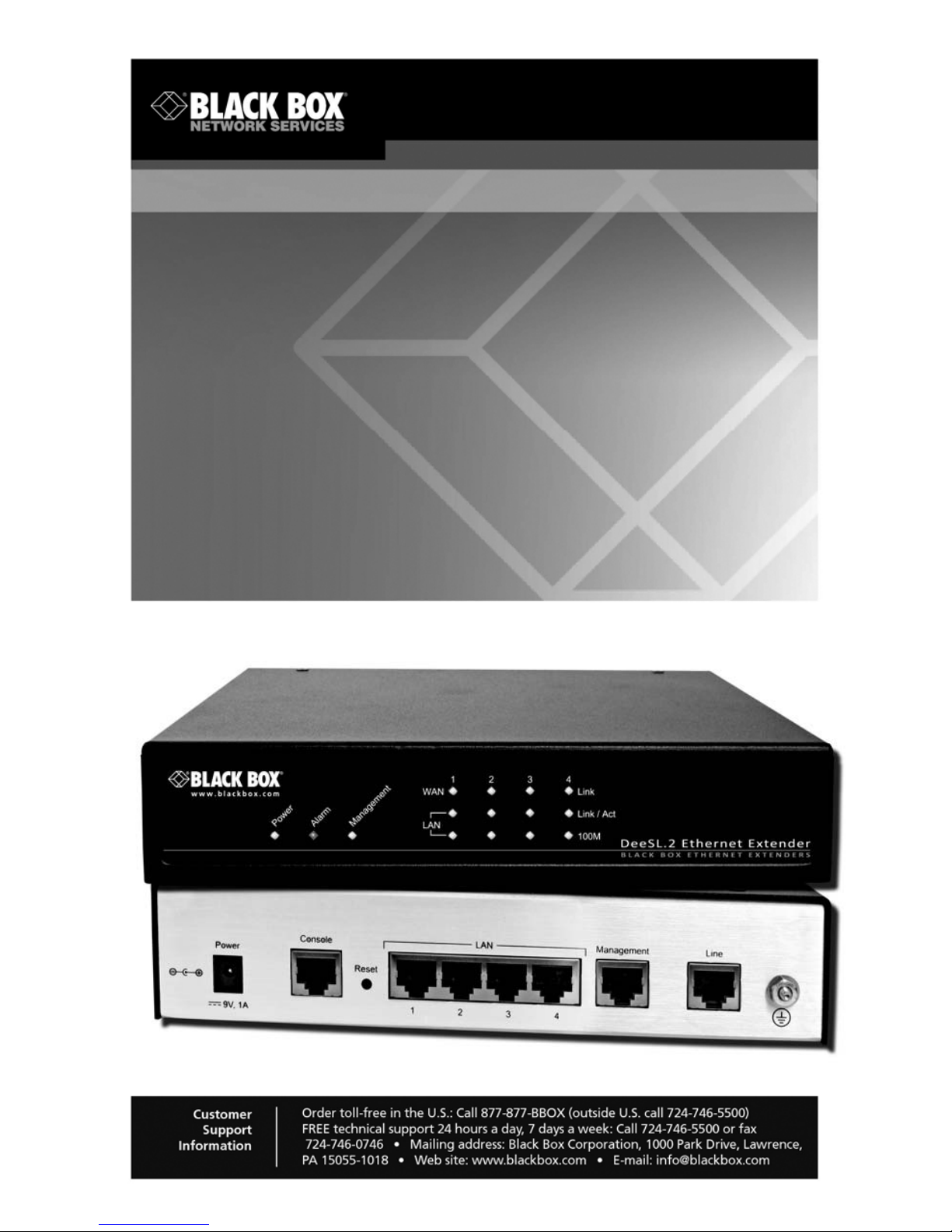
DeeSL.2 Ethernet Extender
Extend corporate LAN communications at higher speeds or at a
longer distance.
Page 2

Black Box DeeSL.2 Ethernet Extender
TABLE OF CONTENTS
1. GENERAL INFORMATION .......................................................................10
1.1 Features ............................................................................................10
1.2 Description........................................................................................ 10
1.3 LB52xA-KIT front Panel.................................................................... 11
1.3.1 LED Descriptions ..................................................................11
1.4 LB52xA-KIT Rear Panel ........................ ................................. .......... 12
1.4.1 Port Descriptions ..................................................................12
1.5 Reset Button..................................................................................... 13
1.6 Ground Terminal............................................................................... 14
2. Applications Overview ............................................................................... 14
2.1 Typical Application ............................................................................14
2.2 Distance Charts................................................................................ 16
2.2.1 Distance Chart LB52xA-KIT Series - Auto Mode...................16
2.2.2 Distance Chart LB52xA-KIT Series - Optimal Mode............. 16
2.2.3 Distance Chart LB52xA-KIT Series - TCPAM - 128 ............. 17
3. Hardware Installation................................................................................. 18
3.1 Planning the Installation ....................................................................18
3.1.1 Network Diagram ..................................................................19
3.1.2 IP Related Information.......................................................... 19
3.1.3 AC Power Mains................................................................... 20
3.1.4 Location and mounting requirements ................................... 20
3.1.5 Installing the LB52xA-KIT..................................................... 20
3.1.6 Connecting cables................................................................ 21
3.1.7 Grounding the LB52xA-KIT and connecting power .............. 21
3.2 Configuring the LB52xA-KIT............................................................. 23
3.2.1 Web configuration requirements ...........................................23
3.3 Console configuration requirements................................................. 23
3.3.1 Telnet configuration requirements ........................................23
4. Web Configuration..................................................................................... 24
4.1 Setting Up the WMI ...........................................................................24
4.1.1 TCP/IP setup ........................................................................24
4.1.2 System Login........................................................................ 25
4.2 Basic Configuration Options............................................................. 26
4.2.1 Operation mode and Management port ................................26
4.2.2 DHCP server......................................................................... 28
4.2.3 LAN....................................................................................... 29
4.2.4 Review and save basic setup changes................................. 31
4.3 Advanced Configuration Options...................................................... 31
4.3.1 LINE ......................................................................................31
4.3.2 VLAN .................................................................................... 34
Page 2
724-746-5500 | blackbox.com
Page 3

Table of Contents
4.3.3 Configuring 802.1Q VLAN Tagging ......................................39
4.3.4 Quality of Service (QoS)....................................................... 41
4.3.5 Rate Limit............................................................................. 54
4.3.6 Flow Control......................................................................... 55
4.4 Status Options.................................................................................. 55
4.4.1 LINE Status ..........................................................................55
4.4.2 Management Status ............................................................. 56
4.4.3 LAN Status........................................................................... 56
4.4.4 Performance Status.............................................................. 57
4.1 Administration Options .....................................................................58
4.1.1 Security Administration .........................................................58
4.1.2 SNMP Administration ........................................................... 61
4.1.3 Remote Syslog..................................................................... 64
4.2 Utility Options................................................................................... 64
4.2.1 System Information ...............................................................65
4.2.2 Configuration Tool................................................................ 65
4.2.3 Upgrade................................................................................ 66
4.2.4 Logout................................................................................... 66
4.2.5 Restart.................................................................................. 67
5. Console and Telnet Configuration............................................................. 67
5.1 Login to the Console Interface ..........................................................67
5.2 Log in using Telnet........................................................................... 68
5.3 Interface commands......................................................................... 68
5.4 Window structure.............................................................................. 69
5.5 Main Menu Tree............................................................................... 70
5.5.1 Menu tree for authorized users .............................................70
5.6 Menu tree for unauthorized users..................................................... 72
5.7 Enable Command Menu................................................................... 73
5.8 Setup Command Menu..................................................................... 75
5.8.1 Line .......................................................................................75
5.8.2 LAN....................................................................................... 77
5.8.3 VLAN.................................................................................... 78
5.8.4 QoS...................................................................................... 82
5.8.5 Rate...................................................................................... 89
5.8.6 Management......................................................................... 90
5.8.7 DHCP ................................................................................... 90
5.8.8 DNS Proxy............................................................................ 92
5.8.9 Host Name............................................................................ 93
5.8.10 Factory Default................................................................... 93
5.9 Status Command Menu.................................................................... 94
5.9.1 LINE Status ..........................................................................94
5.9.2 Interface Status .................................................................... 95
5.10 Show Command Menu..................................................................... 95
724-746-5500 | blackbox.com
Page 3
Page 4

Black Box DeeSL.2 Ethernet Extender
5.11 Write Command................................................................................ 96
5.12 Reboot Command............................ ...... ..... .................................. .... 97
5.13 Ping Command................................................................................. 97
5.14 Administration Command Menu ....................................................... 98
5.14.1 User Profile .........................................................................98
5.14.2 Security............................................................................. 100
5.14.3 SNMP ............................................................................... 101
5.14.4 Supervisor Password and ID............................................ 103
5.15 Utility Command Menu ................................................................... 104
5.15.1 Upgrade main software .....................................................105
5.15.2 Backup system configuration............................................ 105
5.15.3 Restore system configuration........................................... 105
5.16 Exit Command................................................................................ 106
A. Specifications........................................................................................... 107
A.1 Line Connector ...............................................................................107
A.2 Line Modulation ..............................................................................107
A.3 Ethernet Connector .........................................................................107
A.4 LAN Protocols .................................................................................107
A.5 VLAN Support .................................................................................107
A.6 QoS Support ...................................................................................107
A.7 Management Connector .................................................................107
A.8 Management Interface ....................................................................107
A.9 Front Panel Indicators .....................................................................108
A.10 Power Supply ..................................................................................108
A.11 Operating Temperature ..................................................................108
A.12 Storage Temperature ......................................................................108
A.13 Dimensions .....................................................................................108
A.14 Weight .............................................................................................108
B. Port Pin-outs.............................................................................................109
B.1 Console Port ...................................................................................109
B.2 Ethernet ..........................................................................................110
B.3 Line (Black Box) ..............................................................................110
Page 4
724-746-5500 | blackbox.com
Page 5

RADIO FREQUENCY INTERFERENCE STATEMENTS
RADIO FREQUENCY INTERFERENCE STATEMENTS
FEDERAL COMMUNICATIONS COMMISSION AND INDUSTRY CANADA RADIO
FREQUENCY INTERFERENCE STATEMENTS
This equipment generates, uses, and can radiate radio-frequency energy, and if not
installed and used properly, that is, in strict accordance with the manufacturer’s
instructions, may cause interference to radio communication. It has been tested and
found to comply with the limits for a Class A computing device in accordance with the
specifications in Sub p art B of Part 15 of FCC rules, which are designed to provide reasonable protection against such interference when the equipment is operated in a
commercial environment. Operation of this equipment in a residential area is likely to
cause interference, in which case the user at his own expense will be required to take
whatever measures may be necessary to correct the interference.
Changes or modifications not expressly approved by the party responsible for compliance could void the user’s authority to operate the equipment.
This digital apparatus does not exceed the Class A limit s for rad io no is e em is si on from
digital apparatus set out in the Radio Interference Regulation of Industry Canada.
Le présent appareil numérique n’émet pas de bruits radioélectriques dépassant les
limites applicables aux appareils numériques de la classe A prescrites dans le Règle
ment sur le brouillage radioélectrique publié par Industrie Canada.
-
724-746-5500 | blackbox.com
Page 5
Page 6

Black Box DeeSL.2 Ethernet Extender
INSTRUCCIONES DE SEGURIDAD
(Normas Oficiales Mexicanas Electrical Safety Statement)
1. Todas las instrucciones de seguridad y operación deberán ser leídas antes de
que el aparato eléctrico sea operado.
2. Las instrucciones de seguridad y operación deberán ser guardadas para referencia futura.
3. Todas las adver tencias en el aparato eléctrico y en sus instrucciones de operación deben ser respetadas.
4. Todas las instrucciones de operación y uso deben ser seguidas.
5. El aparato eléctrico no deberá ser usado cerca del agua—por ejemplo, cerca de
la tina de baño, lavabo, sótano mojado o cerca de una alberca, etc..
6. El aparato eléctrico debe ser usado únicamente con carritos o pedestales que
sean recomendados por el fabricante.
7. El aparato eléctrico debe ser montado a la pared o al techo sólo como sea
recomendado por el fabricante.
8. Servicio—El usuario no debe inten tar d ar servi cio al equip o eléc trico m ás allá a l o
descrito en las instrucciones de operación. Todo otro servicio deberá ser referido
a personal de servicio calificado.
9. El aparato eléctrico debe ser situado de tal manera que su posición no interfiera
su uso. La colocación del aparato eléctr ico sobre una cama, sofá, alfombra o
superficie similar puede bloquea la ventilación, no se debe colocar en libreros o
gabinetes que impidan el flujo de aire por los orificios de ventilación.
10.El equipo eléctrico deber ser situado fuera del alcance de fuentes de calor como
radiadores, registros de calor, estufas u otros aparatos (incluyendo amplificado
res) que producen calor.
11.El aparato eléctrico deberá ser connectado a una fuente de poder sólo del tipo
descrito en el instructivo de operación, o como se indique en el aparato.
12.Precaución debe ser tomada de tal manera que la tierra fisica y la polarización
del equipo no sea eliminada.
-
13.Los cables de la fuente de poder deben ser guiados de tal manera que no sean
pisados ni pellizcados por objetos colocados sobre o contra ellos, poniendo par
ticular atención a los contactos y receptáculos donde salen del aparato.
Page 6
724-746-5500 | blackbox.com
-
Page 7

INSTRUCCIONES DE SEGURIDAD
14.El equipo eléctrico debe ser limpiado únicamente de acuerdo a las recomendaciones del fabricante.
15.En caso de existir, una antena externa deberá ser localizada lejos de las lineas
de energia.
16.El cable de corriente deberá ser desconectado del cuando el equipo no sea
usado por un largo periodo de tiempo.
17.Cuidado debe ser tomado de tal manera que objectos liquidos no sean derramados sobre la cubierta u orificios de ventilación.
18.Servicio por personal calificado deberá ser provisto cuando:
A. El cable de poder o el contacto ha sido dañado; u
B. Objectos han caído o líquido ha sido derramado dentro del aparato; o
C. El aparato ha sido expuesto a la lluvia; o
D. El aparato parece no operar normalmente o muestra un cambio en su desem-
peño; o
E. El aparato ha sido tirado o su cubierta ha sido dañada.
724-746-5500 | blackbox.com
Page 7
Page 8

Black Box DeeSL.2 Ethernet Extender
SAFETY WHEN WORKING WITH ELECTRICITY
• This device contains no user serviceable parts. This
device can only be repaired by qualified service personnel.
WARNING
• Do not open the devic e when the power cord i s connected .
For systems withou t a power switch and without an exter nal
power adapter, line voltages are present within the device
when the power cord is connected.
• For devices with an external power adapter, the power
adapter shall be a listed Limited Power Source. The mains
outlet that is utilized to power the device shall be within 10
feet (3 meters) of the device, shall be eas ily accessible, and
protected by a circuit bre aker in comp liance w ith local r egulatory requirements.
• For AC powered devices, ensure that the power cable
used meets all applicable standards for the country in
which it is to be installed.
• For AC powered devices which have 3 conductor power
plugs (L1, L2 & GND or Hot, Neutral & Safety/Protective
Ground), the wall outlet (or socket) must have an earth
ground.
Page 8
• For DC powered devices, ensure that the interconnecting
cables are rated for proper voltage, current, anticipated
temperature, flammability, and mechanical serviceability.
• WAN, LAN & PSTN ports (connections) may have hazardous voltages present regardless of whether the device is
powered ON or OFF. PSTN relates to interfaces such as
telephone lines, FXS, FXO, DSL, xDSL, T1, E1, ISDN, Voice,
etc. These are known as “haz ardous net work volt ages” and
to avoid electric shock use caution when working near
these ports. When disconnecting cables for these ports,
detach the far end connection first.
• Do not work on the device or connect or disconnect
cables during periods of lightning activity.
724-746-5500 | blackbox.com
Page 9
WARNING
WARNING
In accordance with the requirements of council
directive 2002/96/EC on Waste of Electrical and
Electronic Equipment (WEEE), ensure that at
end-of-life you sep arate th is product from other
waste and scrap and deliver to the WEEE collection system in your country for recycling.
This device contains no user serviceable parts.
This device can only be repaired by qualified
service personnel .
This device is NOT intended nor approved for
connection to the PSTN. It is intended only for
connection to customer premise equipment.
WARNING
Electrostatic Discharge (ESD) can damage
equipment and impair electrical circuitry. It
occurs when electroni c printed cir cuit cards are
improperly handled and can result in complete
or intermittent failures. Do the following to prevent ESD:
• Always follow ESD prevention procedures
when removing and replacing cards.
• Wear an ESD-preventive wrist strap, ensuring
that it makes good skin contact. Connect the
clip to an unpainted surface of the chassis
frame to safely chann el unwanted ESD vo lt ages
to ground.
• To properly guard against ESD damage and
shocks, the wrist strap and cord must operate
effectively. If no wrist strap is available, ground
yourself by touching the metal part of the chassis.
724-746-5500 | blackbox.com
Page 9
Page 10

Black Box DeeSL.2 Ethernet Extender
1. GENERAL INFORMATION
Thank you for your purchase of this Black Box® product. This product has been thoroughly inspected and tested and is warranted for one year for parts and labor. If any
questions or problems arise during installation or use of this product, contact Black
Box Technical Support at 724-746-5500 or info@blackbox.com.
1.1 FEATURES
• High speed extension with speeds up to 22.8 Mbps
• up to 8-wire (4 pair) Line connection via built-in RJ-45 ports
• 4 auto 10/100Base-Tx, full or half-duplex Ethernet ports for direct connection of
four Ethernet devices
• Extends Ethernet up to 1.8 miles (2.9 km) using 24 AWG/0.5mm wire (192 kbps
speed)
• CE marked
1.2 DESCRIPTION
The Black Box® LB52xA-KIT simplifies and provides cost-effective network extension
by utilizing pre-existing twisted pair infrastructure, which enables service providers to
offer broadband or data backhaul services to businesses, governments and various
institutions o ver ex isting last-mile, copper i nfra stru ctu re. Today, more than ever, opera
tors are finding the business case for leveraging their existing copper networks to be
highly attractive from an ROI and initial investment perspective over fiber roll-outs.
Black Box’s LB52xA-KIT Ethernet Extender incorporates multi-pair bonding to offer an
unmatched rate, reach and reliable Ethernet connectivity, providing symmetrical 22.8
Mbps of bandwidth over 4-pair (8-wire) at distances up to 1.8 miles (2.9 km). The
LB52xA-KIT comes standard with a 4-port fast Ethernet switch with full QoS and CoS
features. VLAN (802.1q) capabilities include 4 levels of priorities, traffic flow control
and rate control . These traf fi c mana geme nt and QoS feat ures en able s ervice pr ovi ders
to provision for differentiated services and/or SLAs.
The following base models are available:
• LB522A-KIT: Ethernet Extender (2-wire), 5.7 Mbps
-
• LB524A-KIT: Ethernet Extender (4-wire), 11.4 Mbps
• LB528A-KIT: Ethernet Extender (8-wire), 22.8 Mbps
Page 10
724-746-5500 | blackbox.com
Page 11
Refer to Appendix A for a complete feature description of the LB52xA-KIT.
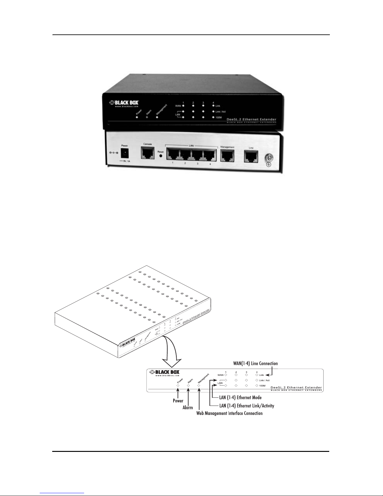
Figure 1.
LB52xA-KIT
1.3 LB52XA-KIT FRONT PANEL
1.3.1 LED Descriptions
The front panel LEDs dis pl ay the st atu s of the po we r, system, Ethernet ports, and Line
Figure 2. show s t he front panel LED indicators and Table 1 provide s a description
port.
of the LED indicators’ behavior.
724-746-5500 | blackbox.com
Figure 2.
LB52xA-KIT front panel LEDs
Page 11
Page 12

Black Box DeeSL.2 Ethernet Extender
Table 1:
Front pane l LEDs
LED Condition Description
Power On Power is applied
Alarm
On
Blink
LINE connection dropped
LINE self-test
Management On Management port is connected
WAN (1-4) LINK
LAN (1-4) LINK/ACT
LAN (1-4) 100M
On
Blink
On
Blink
On
Off
LINE is connected
LINE handshake/transmited/received data
Ethernet is connected
Ethernet link transmitted/received data
LAN port is on 100M mode
LAN port is on 10M mode
1.4 LB52XA-KIT REAR PANEL
1.4.1 Port Descriptions
The Black Box LB52xA-KIT rear panel ports are shown in the figure below and
described in
Table 2.
Power Console
9V, 1A
Reset
Figure 3.
P
ow
e
r
Co
n
so
le
9
V
,
1
A
Re
set
L
A
N
M
an
agem
LAN
Management
LB52xA-KIT rear panel
ent
Line
Line
Page 12
724-746-5500 | blackbox.com
Page 13

Table 2:
Port descriptions
Port Description
Power Power adaptor inlet: Input volta ge 9VDC
Used for service a nd m aint ena nce, the Console
port, an RS-232 RJ-45 connector with EIA-561
pinout, connects the router to a serial terminal
Console
(RS-232 control port)
such as a PC or ASCII terminal (also called a
dumb terminal). Asy nchronous def ault data rate
9600 bps, hardware DSR and DTR signals for
external modems are wired directly together
internally.
Reset
LAN (LAN Ethernet
Ports 1-4)
Reset button for rebooting or loading factory
default settings
10/100Base-Tx full-/half-duplex, RJ-45, auto
detection and fallback, connects the unit to an
Ethernet LAN.
Management RJ-45 for management port
Line Interface for WAN port (RJ-45)
NOTE: For port pinout information, see Append ix B. on page 109.
1.5 RESET BUTTON
• To restart the unit with the current startup configuration—Press the Reset bu tton
for less than 1 second and release. The LB52xA-KIT will restart with the current
startup configuration.
• To restart the unit with fac tory defau lt config uration—Pres s the Reset button for 5
seconds until the Power LED starts blinking. The unit will restart with factory
default configuration.
• T o res tar t the un it in bootl oader mo de (to be us ed only by trai ned Blac k Box tec hnicians)—Start with the unit powered off. Press and hold the Reset button while
applying power to t he unit. Releas e the Reset button when the Power LED st art s
blinking so the unit will enter bootloader mode.
724-746-5500 | blackbox.com
Page 13
Page 14

Black Box DeeSL.2 Ethernet Extender
1.6 GROUND TERMINAL
The marked lug or terminal should be connected to the building protective earth bus. The function of protective earth does not serve the purpose of providing protection against electrical shock, but instead
enhances surge suppression on the lines for installations where suitable
bonding facilities exist. The connector type is M3 machine screw.
2. APPLICATIONS OVERVIEW
The Black Box LB52xA-KIT sim plifie s and provid es cos t eff ectiv e network ex tension by
utilizing pre-existing twisted pair infrastructure. This enables service providers to offer
broadband or data backhaul services to businesses, governments and various institutions over existing last-mile, copper infrastructure. Today, more than ever, operator s
are finding the bu siness case for levera gin g th eir e xi sti ng c op per n etw o rks to be highly
attractive from an ROI and initial investment perspective over fiber roll-outs.
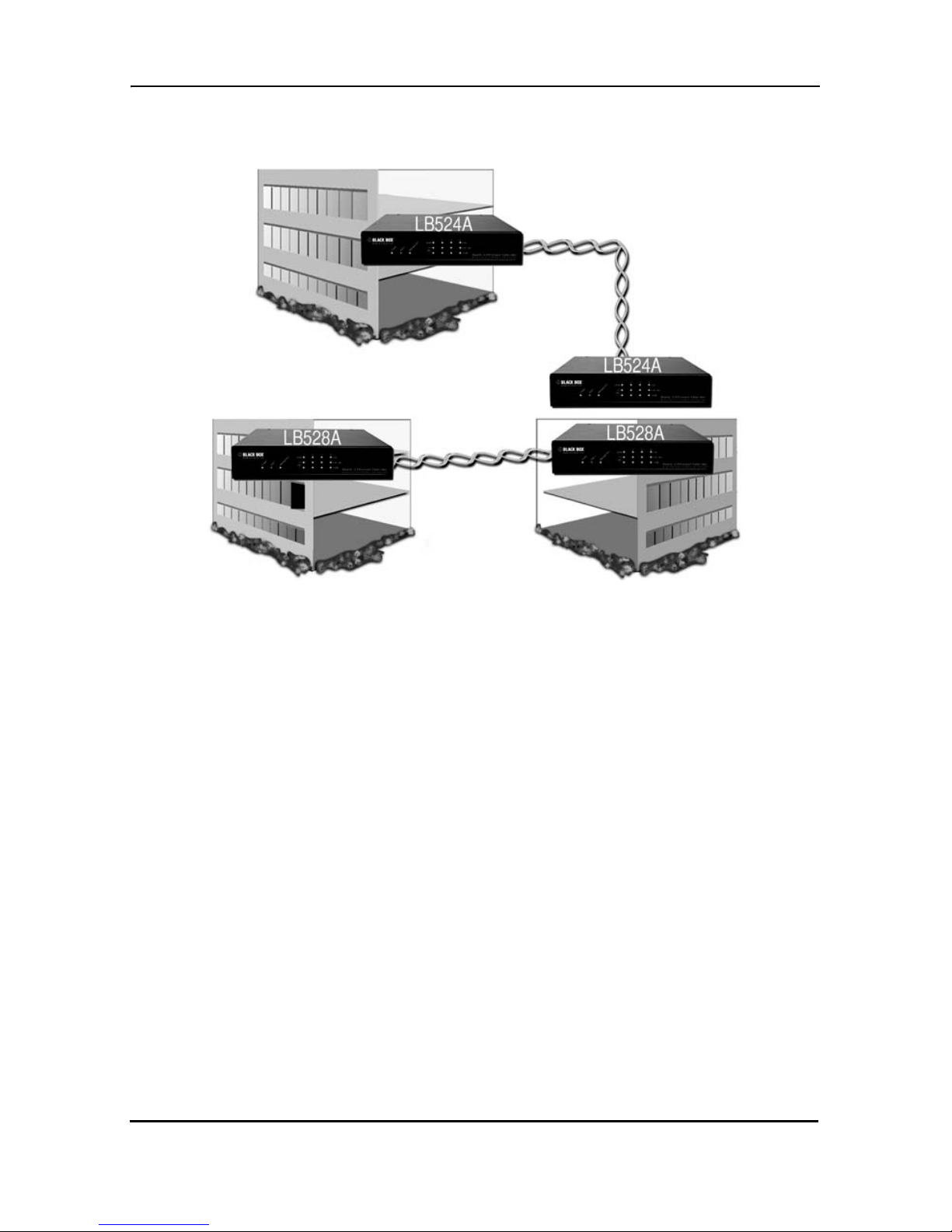
2.1 TYPICAL APPLICATION
The Black Box Exte nders are the perfect fit f or s im ple , c ost -effective high speed Ethernet Extension. They allow customers to take advantage of the existing copper infrastructure to connect remote LANs across distances and at speeds previously
unthought-of. The auto-rate feature ensures the highest speed is achieved on each
connection, and the plug and play operation ensures they are up and running in sec
onds. Add in the 4 x auto-sensing full/half duplex 10/100Base-TX Ethernet ports with
the integrated crossover switch to make setup even easier. The value of these Ether
net Extenders can’t be beat!
• Auto-Rate Feature—The advanced auto-rate algorithm automatically determines the best possible rate for each connection and sets up each extender
without any need for user interface.
• Plug and Play—Just unpack the extenders, plug them into each end of the
extension, power them up, and they are up and running. It doesn’t get any eas
ier!
• High Speed/Long Reach—These Ethernet Extenders provide the best combi-
nation of speed and distance seen anywhere in the industry!
-
-
-
Page 14
724-746-5500 | blackbox.com
Page 15
Applications Overview
Figure 4.
LB52xA-KIT application
724-746-5500 | blackbox.com
Page 15
Page 16

Black Box DeeSL.2 Ethernet Extender
2.2 DISTANCE CHARTS
2.2.1 Distance Chart LB52xA-KIT Series - Auto Mode (TCPAM-32/16)
Table 3:
Distance Chart LB52xA-KIT
Line Rate Distance
Line
Speed
522A
2-Wire
524A
4-Wire
528A
8-Wire
26 AWG/
0.4mm
24 AWG/
0.5mm
22 AWG/
0.65mm
N= kbps kbps kbps kft km kft km kft km
3 192 384 768 17.0 5.2 21.5 6.6 27.5 8.4
4 256 512 1024 17.0 5.2 20.5 6.2 27.0 8.2
8 512 1024 2048 14.5 4.4 17.5 5.3 23.5 7.2
12 768 1536 3072 13.5 4.1 16.0 4.9 21.5 6.6
16 1024 2048 4096 12.5 3.8 15.0 4.6 20.0 6.1
20 1280 2560 5120 12.0 3.7 14.5 4.4 19.0 5.8
24 1536 3072 6144 11.5 3.5 14.0 4.3 18.5 5.6
32 2048 4096 8192 11.0 3.4 13.5 4.1 17.5 5.3
36 2304 4608 9216 11.0 3.4 13.0 4.0 17.0 5.2
60 3840 7680 15360 9.0 2.7 11.0 3.4 14.5 4.4
72 4608 9216 18432 8.5 2.6 10.0 3.0 13.5 4.1
89 5696 11392 22784 7.5 2.3 9.0 2.7 12.0 3.7
2.2.2 Distance Chart LB52xA-KIT Series - Optimal Mode (TCP AM - 128)
Table 4:
Distance Chart LB52xA-KIT Series - Optimal Mode
Line Rate Distance
Line
Speed
522A
2-Wire
524A
4-Wire
528A
8-Wire
26 AWG/
0.4mm
24 AWG/
0.5mm
22 AWG/
0.65mm
N= kbps kbps kbps kft km kft km kft km
7 448 896 1792 20.0 6.1 24.0 7.3 31.0 9.4
8 512 1024 2048 19.0 5.8 23.0 7.0 30.0 9.1
10 640 1280 2560 18.0 5.5 20.5 6.2 28.0 8.5
11 704 1408 2816 17.0 5.2 19.0 5.8 26.5 8.1
16 1024 2048 4096 16.0 4.9 18.0 5.5 24.5 7.5
20 1280 2560 5120 15.0 4.6 17.0 5.2 23.0 7.0
Page 16
724-746-5500 | blackbox.com
Page 17

Line Rate Distance
Line
Speed
522A
2-Wire
524A
4-Wire
528A
8-Wire
26 AWG/
0.4mm
24 AWG/
0.5mm
22 AWG/
0.65mm
N= kbps kbps kbps kft km kft km kft km
22 1408 2816 5632 14.0 4.3 15.5 4.7 21.0 6.4
27 1728 3456 6912 13.0 4.0 14.5 4.4 20.0 6.1
34 2176 4352 8704 12.0 3.7 14.5 4.4 18.5 5.6
39 2496 4995 9987 11.0 3.4 13.0 4.0 17.0 5.2
44 2816 5362 11264 10.0 3.0 12.0 3.7 15.5 4.7
53 3392 6784 13568 9.0 2.7 10.5 3.2 13.5 4.1
73 4681 9344 18688 8.0 2.4 9.5 2.9 12.5 3.8
89 5696 11392 22784 7.0 2.1 8.5 2.6 10.5 3.2
110 7040 14080 28160 6.0 1.8 7.0 2.1 9.0 2.7
125 8000 16000 32000 5.0 1.5 6.0 1.8 7.5 2.3
152 9728 19456 38912 4.0 1.2 4.5 1.4 6.0 1.8
164 10496 20992 41984 3.0 0.9 3.5 1.1 4.5 1.4
198 12792 25584 51168 2.0 0.6 2.5 0.8 3.0 0.9
2.2.3 Distance Chart LB52xA-KIT Series - TCPAM - 128
Table 5:
Distance Chart LB52xA-KIT Series - TCPAM-128
Line Rate Distance
Line
Speed
522A
2-Wire
524A
4-Wire
528A
8-Wire
26 AWG/
0.4mm
24 AWG/
0.5mm
22 AWG/
0.65mm
N= kbps kbps kbps kft km kft km kft km
5 320 640 1280 22.0 6.7 26.5 8.1 34 10.4
6 384 768 1536 21.0 6.4 25.5 7.8 32.5 9.9
8 512 1024 2048 20.0 6.1 24.0 7.3 31.0 9.4
9 576 1152 2304 19.0 5.8 23.0 7.0 29.5 9.0
9 576 1152 2304 18.0 5.5 21.5 6.6 27.5 8.4
12 768 1536 3072 17.0 5.2 20.5 6.2 26.5 8.1
16 1024 2048 4096 16.0 4.9 19.5 5.9 24.5 7.5
20 1280 2560 5120 15.0 4.6 18.0 5.5 23.0 7.0
22 1408 2816 5632 14.0 4.3 16.5 5.0 21.5 6.6
27 1728 3456 6912 13.0 4.0 15.7 4.8 20.0 6.1
34 2176 4352 8704 12.0 3.7 14.5 4.4 18.5 5.6
724-746-5500 | blackbox.com
Page 17
Page 18

Black Box DeeSL.2 Ethernet Extender
Line Rate Distance
Line
Speed
N= kbps kbps kbps kft km kft km kft km
39 2496 4992 9984 11.0 3.4 13.0 4.0 17.0 5.2
45 2880 5760 11520 10.0 6.0 12.0 3.7 15.5 4.7
53 3392 6784 13568 9.0 2.7 10.5 3.2 13.5 4.1
74 4736 9472 18944 8.0 2.4 9.5 2.9 12.5 3.8
90 5760 11520 23040 7.0 2.1 8.5 2..6 10.5 3.2
112 7168 14336 28672 6.0 1.8 7.0 2.1 9.0 2.7
126 8064 16128 32256 5.0 1.5 6.0 1.8 7.5 2.3
152 9728 19456 38912 4.0 1.2 4.5 1.4 6.0 1.8
167 10688 21376 42752 3.0 0.9 3.5 1.1 4.5 1.4
198 12672 25344 50688 2.0 0.6 2.5 0.8 3.0 0.9
220 14072 28144 56288 1.0 0.3 1.0 0.3 1.5 0.5
239 15288 30476 61152 0.5 0.2 0.5 0.2 1.0 0.3
522A
2-Wire
524A
4-Wire
528A
8-Wire
26 AWG/
0.4mm
24 AWG/
0.5mm
22 AWG/
0.65mm
3. HARDWARE INSTALLATION
This chapter contains information for planning the installation of the LB52xA-KIT with
the following installation procedures:
• “Unpacking the LB52xA-KIT” on page 20 lists the contents of the shipping box
• “Connecting cables” on page 21 describes how to install the port cables
• “Grounding the LB52xA-KIT an d connecting po wer” on page 21 describes how to
ground and connect the power source
3.1 PLANNING THE INSTALLATION
Before beginnin g the actual inst allation, we stron gly re co mm end that you gather al l th e
information you will need to install and set up the device.
• Create a network diagram
• Gather IP related information
• Install the hardware and software needed to configure the LB52xA-KIT
• Verify power source reliability
Page 18
724-746-5500 | blackbox.com
Page 19
Hardware In s ta llation
When you finish preparing for your installation, go to section “Installing the LB52xAKIT” on pag e 20 to install the device.
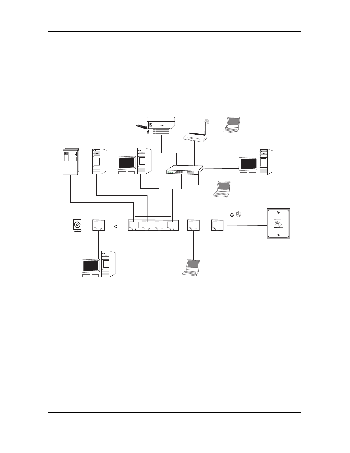
3.1.1 Network Diagram
Draw a network overview diagram that displays all neighboring IP nodes, connected
elements and telephony
to the LB52xA-KIT.
ServerRAID Drive
components. Figure 5. shows possible network connections
Printer
WAP
Notebook
Desktop PC
Switch
Desktop PC
Notebook
DC 9V
+-
CONSOLE
RST
Desktop PC
Figure 5.
LAN
LAN
MGMT
LINE
Laptop computer
LB52xA-KIT connection diagram
3.1.2 IP Related Information
Before you can set up the basic IP connectivity for your LB52xA-KIT series you should
have the following information:
• IP addresses used for Ethernet LAN and WAN ports
• Subnet mask used for Ethernet LAN and WAN ports
You will need a PC (or equivalent) with a VT-100 emulation program (e.g. HyperTerminal) to configure the software on your LB52xA-KIT.
724-746-5500 | blackbox.com
Page 19
Page 20
Black Box DeeSL.2 Ethernet Extender
3.1.3 AC Power Mains
If you suspect th at your AC power is not reliable, for exampl e if room lights fl ic ker often
or there is machinery with large motors nearby, have a qualified professional test the
power. Install a power conditioner if necessary. Refer to “Grounding the LB52xA-KIT
and connecting power” on page 21.
The mains outlet that is utilized to power the equipment must be
within 1
ble.
WARNING
NOTE: When setting up your LB52xA-KIT, you must consider cable-length limitations
and potential el ect romagn etic in terferen ce (EMI) a s defin ed by the applic able l ocal an d
international regulations. Ensure that your site is properly prepared before beginning
installation.
3.1.4 Location and mounting requirements
foot (3 meters) of the device and shall be easily accessi-
The LB52xA-KIT is intended to be placed on a desktop or a similar sturdy, flat surface
that offers easy access to the cables. Additionally, you should consider the need to
access the unit for future upgrades and maintenance.
This comple tes the plann ing ph ase fo r installation. The next secti on beg ins th e in st allation procedures.
3.1.5 Installing the LB52xA-KIT
Unpacking the LB52xA-KIT
Inspect the shipping carton for external damage. Note any damage before removing
the container contents. Report any equipment damage to the shipping carrier immedi
ately for claim purposes. Save all packing material in case you need to return an item
to the factory for servicing.
The LB52xA-KIT comes with the following items:
• LB52xA-KIT
• An RJ-45-to-RJ-45 cable for use with the console and Ethernet ports
-
• A DB-9-to-RJ-45 (EIA-561) adapter for connecting a PC’s serial port to the
LB52xA-KIT console port
Page 20
724-746-5500 | blackbox.com
Page 21
Hardware In s ta llation
NOTE: Power cables are shipped separately from the LB52xA-KIT
3.1.6 Connecting cables
The Interconnecting cables must be acceptable for external use
and must be rated for the proper application with respect to volt
age, current, anticipated temperature, flammability, and mechani-
CAUTION
1. Connect the Ethernet cable to the Management port. LB52xA-KIT supports audiMDIX switching so you may use a crossover or straight-through cable.
2. Connect one end of a phone cable to the LINE po rt and the oth er end of the cable
to a wall jack.
cal serviceability.
Do not work on the system or connec t or disco nnect cables during
periods of lightning activity.
WARNING
-
3.1.7 Grounding the LB52xA-KIT and connecting power
When connecting to the power source, it is important to establish a good grounding
connection first, and then the power connection. Do the following:
1. Assemble a ground wire using #10 AWG wire with green-colored insulation and
two ring terminals . Make th e w ire lo ng enou gh to reac h on e of the following earth
ground sources:
• The building ground rod (general ly loca ted at the site’s main service entrance)
• A sprinkler system pipe
• A cold-water pipe
• Building structural steel
724-746-5500 | blackbox.com
Page 21
Page 22

Black Box DeeSL.2 Ethernet Extender
Figure 6.
2. Install the grounding wire between the grounding stud (see Figure 6.) and the
grounding source.
3. Connect the power adapter to the DC 9V port on the LB52xA-KIT, and then connect to the power source.
Mains Voltage: Do not open the case the when the power cord is
attached. Line voltages are present within the power supply when
the power cords are connected . The mai ns outlet that is utilized to
WARNING
WARNING
power the device shall be within 10 feet (3 meters) of the device,
shall be easily accessible, and protected by a circuit breaker.
The LB52xA-KIT is not shipped with power cables. For AC powered units, ensure that the power cable used meets all applicable
standards for the country in wh ich it is to be inst alled, and that it is
connected to a wall outlet that has earth ground.
Grounding stud
The power supply automatica lly adjusts to accept an input volt a ge
from 100 to 240 VAC(50/60 Hz).
IMPORTANT
Page 22
724-746-5500 | blackbox.com
Page 23

Hardware In s ta llation
3.2 CONFIGURING THE LB52XA-KIT
There are three different ways you can configure the LB52xA-KIT—the serial console,
Telnet or a web browser.
3.2.1 Web configuration requirements
Make sure that the PC you use for configuration has an Ethernet adapter and TCP/IP
installed.
The LB52xA-KIT provides a browser interface that allows you to configure and manage the Ethernet Extender. After you set up the IP address for the LB52xA-KIT, you
can access the Ethernet Exten der' s Web interface a ppl ic ations directly in your browser
by entering the IP address. You can then use your Web browser to manage and configure the unit from a PC.
NOTE: For detailed information on configuring the LB52xA-KIT through the Web interface, see Section 4., “Web Configuration” on page 24 .
3.3 CONSOLE CONFIGURATION REQUIREMENTS
To configure the LB52xA-KIT throug h the s erial console , you c an di rectly connec t a ter minal or a PC equipp ed with a te rminal -emul ation pro gram (suc h as Hype r Terminal) to
the Ethernet Extender's console port.
Use the supplied serial cable (RJ-45 to DB9F) to connect the LB52xA-KIT to a PC.
After marking the connection, configure the terminal-emulation program to use the fol
lowing parameters:
• 9600 bps
• 8 data bits
• no parity
• 1 stop bit
NOTE: For detailed information on configuring the LB52xA-KIT through the serial console, see Section 5., “Console and Telnet Configuration” on page 67.
3.3.1 Telnet configuration requirements
-
Make sure that the PC you use for configuration has an Ethernet adapter and TCP/IP
installed. The LB52xA-KIT supports Telnet for remote configuration. The command is
“telnet 192.168.1.1”. When prompted for the username and password for remote
724-746-5500 | blackbox.com
Page 23
Page 24

Black Box DeeSL.2 Ethernet Extender
login, use admin for both fields. All display screens are the same as the serial console
configuration.
The default IP address is 192.168.1.1, but you may change the IP address for your
application.
NOTE: For detailed information on configuring the LB52xA-KIT through Telnet, see
Section 5., “Console and Telnet Configuration” on page 67.
4. WEB CONFIGURATION
The LB52xA-KIT provides a browser interface that allows you to configure and manage the Ethernet Extender. Make sure that the PC you use for configuration has an
Ethernet adapter and TCP/ IP inst alled . After y ou set up th e IP address for the LB52x AKIT, you can access the Ethernet Ext ender's W eb in terf ace app licati ons di rectly in your
browser by entering the IP address. You can then use your Web browser to manage
and configure the unit from a PC.
4.1 SETTING UP THE WMI
This section introduces the configuration and functions of the Web Management Interface (WMI). The WMI is an H TML-ba sed man ageme nt i nterface th at allows you to eas ily set-up and manage the LB52xA-KIT.
The LB52xA-KIT offers all monitoring and management features that allow users to
manage this LB52xA-KIT form anywhere on the network through a standard browser
such as Internet Explorer.
4.1.1 TCP/IP setup
When DHCP is enabled, the LB52xA-KIT acts as a DHCP server in your network. The
LB52xA-KIT will automatically assign IP address for the management port connection.
To set up TCP/IP on a Windows PC:
1. Click the Start button. Select the Control Panel.
2. Double-click on the Network icon.
3. In the Configuration window, select the TCP/IP protocol line that has been associated with your network card and then click the Property icon.
Page 24
724-746-5500 | blackbox.com
Page 25
Web Configuration
4. Click on the IP address tab and select Obtain IP address automatically. Click
OK.
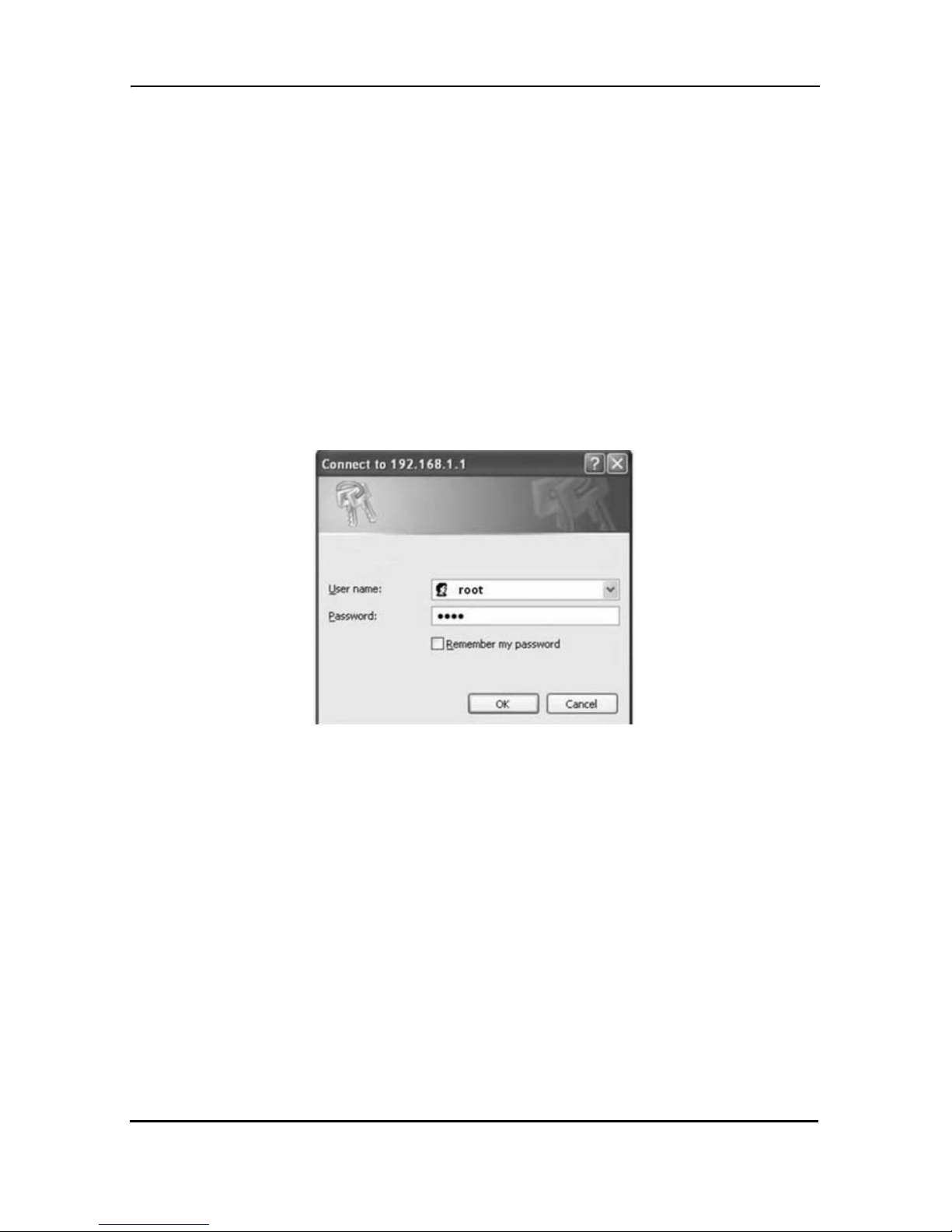
4.1.2 System Login
You may use a web browser such as Internet Explorer on your PC to connect the
LB52xA-KIT. Type “http://” and the IP address, such as “http://192.168.1.1”.
The default IP address and sub net-mask of the Management port of the LB52xA-KIT
are 192.168.1.1 and 255.255.255.0. If DHCP is disabled, your PC can set the same
net-mask, such as 192.168.1.x where x is a number from 2 to 254.
T ype the def ault us ername root and d efault password root and then click OK. For sys-
tem security, you should change the user name and password after initial configuration.
Figure 7.
System login screen
724-746-5500 | blackbox.com
Page 25
Page 26
Black Box DeeSL.2 Ethernet Extender
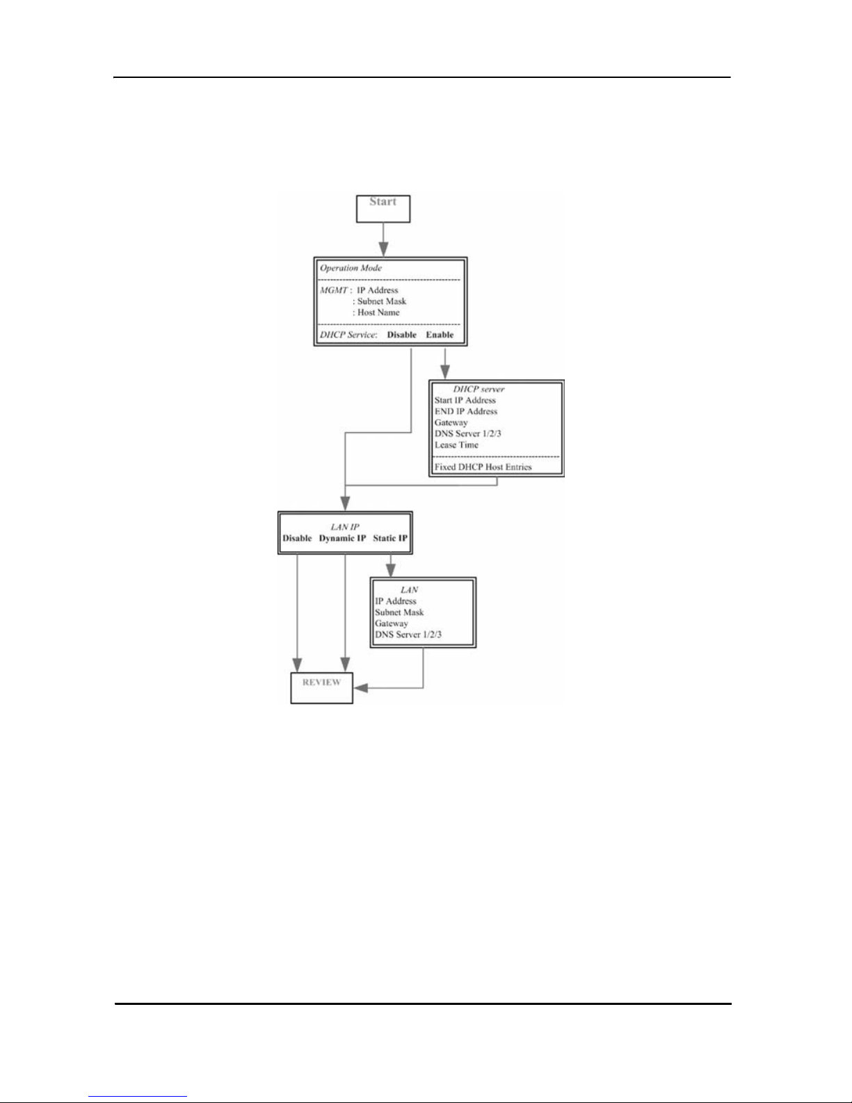
4.2 BASIC CONFIGURATION OPTIONS
This section contains information for setting up the Operation mode and Management
port IP, DHCP server, and LAN via the WMI.
ing basic setup via the WMI for the LB52xA-KIT.
Figure 8. shows a flowchart demonstrat-
4.2.1 Operation mode and Management port
To configure the operation mode and Management port in the WMI:
Page 26
724-746-5500 | blackbox.com
Figure 8.
Basic setup flowchart
Page 27
Web Configuration
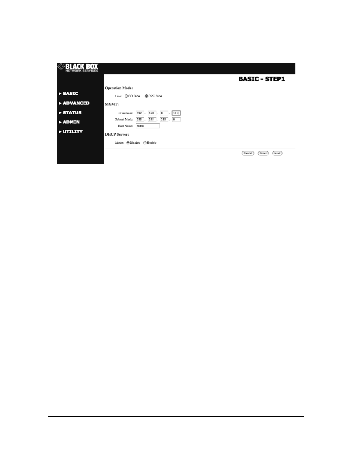
1. From the main menu, clic k Basic to display the basic installation page.
Figure 9.
Operation mode and Management port setup page
2. For Operation mode, select th e rad io but ton for CPE (Customer Premises Equipment) or CO (Central Office). When using a “LAN to LAN” connection, one side
must be set as CO and the other side must be set as CPE.
3. Enter information for the Management port. The LB52xA-KIT requires an IP
address to be managed over the network. The factory default IP address is
192.168.1.1. The subnet mask specifies the network number portion of an IP
address. The factory default subnet mask is 255.255.255.0. You can configure
another IP address and a different subnet mask for management purposes.
• IP: 192.168.1.1
• Subnet Mask: 255.255.255.0
• Host Name: SOHO
NOTE: Some ISP providers require the Host Name as identification. You may check
with your ISP to see if your Internet service has been configured with a host name. In
most cases, you can ignore this field.
4. Select an option for Trigger DHCP Service. If you don't need the DHCP service,
select Disable.
5. Click Next to commit your changes and conti nue to the DHCP Server page (refer
to the next section).
724-746-5500 | blackbox.com
Page 27
Page 28

Black Box DeeSL.2 Ethernet Extender
4.2.2 DHCP server
Dynamic Host Configuration Protocol (DHCP) is a communication protocol that
allows network administrators to manage and automate the assignment of Internet
Protocol (IP) addresses in an organization's network. Each machine that can connect
to the Internet requires a unique IP address. When an organization sets up the users
with a connection to the Internet, an IP address must be assigned to each machine.
Without DHCP, the IP address must be entered manually at each computer. If computers move t o another lo cation in another part of the network, a new IP address must be
entered. DHCP lets a network administrator supervise and distribute IP addresses
from a central point and automatically sends a new IP address when a computer is
plugged into a different place in the network. The embedded DHCP server assigns
network configuration information to 253 users (max) accessing the Internet in the
same time. For e xa mple, if the LAN IP addre ss is 1 92. 168 .0.1 , th e IP range of the LAN
is 192.168.0.2 to 192.168.0.254.
To set up the DHCP Server for the LB52xA-KIT:
1. Click on Basic from the main menu, set up the Operation Mode and Manage-
ment port, then click Next to reac h the DHCP Server page.
2. The DHCP server assigns the IP fro m the Start IP Address to t he End IP Address.
The legal IP address range is from 0 to 255, but 0 is reserved as the network
name and 255 is reserved for broadcast. This implies that the legal IP address
range is from 1 to 254. That means you cannot assign an IP greater than 254 or
less than 1.
3. A Lease Time of 72 hours indicates that the DHCP server will reassign IP information every 72 hours, whi ch is the defaul t value for the LB52xA-KIT. You can set
up the Lease Time for a range from 1 to 720 hours according to your application.
4. If you assign a fixed IP address to a de vice whi le using DHCP, you must enter the
device's MAC address in the Table of Fixed DHCP Host Entries.
Page 28
724-746-5500 | blackbox.com
Page 29

Web Configuration
5. Click Next to commit your changes and continue to the LAN page (refer to the
next section).
Figure 10.
Basic DHCP setup
4.2.3 LAN
To configure LAN settings through the WMI:
1. Click on Basic from the main menu. Set up the Operation Mode and Manage-
ment port, then click Next. Set up the DHCP Server, then clic k Next to reach the
LAN page.
724-746-5500 | blackbox.com
Page 29
Page 30

Black Box DeeSL.2 Ethernet Extender
Figure 11.
LAN setup page
2. Choose an option for the LAN Type. If you select Disable or Dynamic IP, click
Next at the bo ttom o f the s creen to sav e your chang es. If you s elect St atic IP, you
can enter information for IP, Subnet Mask, Gateway and DNS Server's IP.
3. If you select Static IP as the LAN Type, enter details in the St atic IP section. Th e
default values for Static IP are:
• IP Address: 192.168.2.1
• Subnet Mask: 255.255.255.0
• Gateway: 0.0.0.0
• DNS Server 1: 168.95.1.1
• DNS Server 2: 168.95.192.1
4. Click Next to commit your changes and continue to the Rev iew page (refer to the
next section).
Page 30
724-746-5500 | blackbox.com
Page 31

Web Configuration
4.2.4 Review and save basic setup changes
1. Once you have entered information on the pages for Operation Mode and Management Port, DHCP Server, and LAN, the Basic Setup Review page will dis-
play to confirm your changes.
Figure 12.
2. Look over the Review page to confirm the desired settings.
3. Click Restart to reboot the LB52xA-KIT with the new settings.
4. Click Continue to configure other options.
Review and save basic setup changes
4.3 ADVANCED CONFIGURATION OPTIONS
This section contains information for setting up advanced options for the LB52xA-KIT
via the WMI. Advanced setup contains LB52xA-KIT Line, VLAN, QoS and Rate Con
trol parameters.
NOTE: The advanced functions are only intended for administrators. The incorrect
advanced settings will affect the performance of the LB52xA-KIT or cause system
errors and disconnection.
4.3.1 LINE
Click on LINE under Advanced on the m ain menu to reach the LINE advanced co nfi g -
uration page. You can setup the Link (number of wires), Annex Type, TCPAM Type,
-
724-746-5500 | blackbox.com
Page 31
Page 32

Black Box DeeSL.2 Ethernet Extender
Main Rate, SNR Margin, and Line Probe settings for LINE parameters (refer to the following sections to explore each of the configuration options).
Figure 13.
Link
Select the line type for your model from the Link drop-down list. Line type means how
many wires you want to use on the line side. For example, you can select 2-wire, 4wire or 8-wire line type for the 8-wire model.
Table 6:
522A 2-Wire model
Model Type
Annex Type
Select the appropriate Annex type from the drop-down list. Annex AF describes the
transmission and performance requirements for North America. Annex BG describes
performance and transmission requirements for Europe.
524A 4-Wire model
528A 8-Wire model
LINE page
Line Type Chart
Line Type
2-Wire 4-Wire 8-Wire
•
• •
• • •
Page 32
724-746-5500 | blackbox.com
Page 33

Web Configuration
TCPAM Type
TCPAM (Trellis Coded Pulse Amplitude Modulation) is the standard used for line coding. Select the TCPAM type from the drop-down list. Auto is the default option for
TCPAM. You can also manually set the TCPAM type.
Main Rate
Select the line rate for your model fro m the Main Rate drop-down list. The main rate is
the multiple of 64kbps, 128kbps, or 256kbps- depending on your model type. Use the
table below to determine the best main rate for your model.
Table 7:
Model Type Multiple
LB522A-KIT 2-wire 64 192-3840 768-5696 128-15296
LB524A-KIT 4-wire 128 384-7680 1536-11392 256-30592
LB528A-KIT 8-wire 256 768-15360 3072-22784 512-61184
Main Rate Chart
TCPAM - 16
= 3-60
TCPAM - 32
= 12-89
TCPAM -
128 = 2-239
SNR Margin
Select the desired SNR Margin value from the drop-down list. SNR margin is an index
of line connection quality. You can see the actual SNR margin in STATUS. You will
experience better line connection quality for larger SNR margin values.
For example, if you set the SNR margin to 5, the LINE connection will drop and reconnect when the SNR margin is lower than 5. On the other hand, the device will reduce
the line rate and reconnect for better line connection quality. You may select the SNR
margin from the range -10 to 21.
Line Probe
For adaptive mode applications, set the Line Probe to Enable. The LB52xA-KIT will
adapt the data rat e ac cord ing to the line status . The s creen w il l prom pt the p a r am ete rs
that will be written in NVRAM. Check the parameters before writing in NVRAM.
For all other applications, set the Line Probe to Disable.
Click Restart to reboot the LB52xA-KIT with the new settings. Click Continue to con-
figure other options.
724-746-5500 | blackbox.com
Page 33
Page 34

Black Box DeeSL.2 Ethernet Extender
4.3.2 VLAN
Click on VLAN under Advanced on the main menu to reach the VLAN advanced con-
figuration page.
Figure 14.
VLAN page
VLAN (Virtual Local Area Network) allows a physical network to be partitioned into
multiple logical networks. Devices on a logical network belong to one group. A device
can belong to mor e than one group. Wi th VLAN, a dev ice ca nnot dire ctly t alk to or hear
from devices that are not in the same group.
With MTU (Multi-Tenant Unit) applications, VLAN is vital in providing isolation and
security among the subscribers. When properly configured, VLAN prevents one sub
-
scriber from accessing the network resources of another on the same LAN.
VLAN also increases network performance by limiting broadcasts to a smaller and
more manageable logical broadcast domain. In traditional switched environments, all
broadcast packets go to each individual port. With VLAN, all broadcasts are confined
to a specific broadcast domain.
You can select from two types of VLAN: 802.1Q Tag-Based VLAN and Port-Based
VLAN. The VLAN Setup screen changes depending on whether you choose 802.1Q
Tag-Based VLAN type or Port Based VLAN type. The IEEE 802.1Q define s the opera
tion of VLAN bridges that permit the definition, operation, and administration of VLAN
topologies within a bridged LAN infrastructure.
Figure 15. on the following page shows a diagram of possible VLAN connections.
Page 34
724-746-5500 | blackbox.com
Page 35

VID 20
Web Configuration
WAN2
WAN1
WAN3
WAN4
WAN5
VID 30VID 10
WAN6
WAN7
WAN8
Backbone
LAN1
VID 10
Long Range
Ethernet Extender
LAN2
LAN3
VID 20
Figure 15.
VLAN Diagram
724-746-5500 | blackbox.com
LAN4
VID 30
Page 35
Page 36

Black Box DeeSL.2 Ethernet Extender
802.1Q Tag-Based VLAN
Click on VLAN under Advanced on the main menu to reach the VLAN advanced con-
figuration page. Then, select the radio button for 802.1Q Tag-Based VLAN to display
the configuration options.
Figure 16.
• VID (Virtual LAN ID): A number to identify the VLAN segment. Select from 1 to
4094.
• PVID (Port VID): An untagged member of the default VLAN. Select from 1 to
4094.
• Link Type: Select from Access or Trunk. Access m eans the p ort can receiv e or
send untagged packets. Trunk means that the port can receive or send tagged
packets.
In 802.1q, the VLAN information is written into the Ethernet packet itself. Each packet
carries a VLAN ID (Virtual LAN ID) called a tag. This tag allows VLANs to b e config
ured across multiple switches.
NOTE: VLAN tags may be stripped by the hardware or the software.
When using 802.1q, four bytes are added to the Ethernet frame, and 12 bits are used
for the VLAN ID. Theoretically, there can be up to 4096 VLANs per network.
802.1Q Tag-Based VLAN page
-
Page 36
724-746-5500 | blackbox.com
Page 37

Web Configuration
An Ethernet packet that contains a VLAN ID is called a tagged packet. An Ethernet
packet without a VLAN ID is called an untagged packet. Typically, all packets leave
untagged, unless tagged by the adapter prior to arriving at the switch port.
Egress and Ingress Rules. Egress rules determine which frames can be transmitted
out of a port, based on the Egress List of the associated VLAN. Each VLAN has an
Egress List that specifies the ports out of which frames can be forwarded, and speci
fies whether the frames will be transmitted as tagged or untagged frames.
Ingress rules are a means of filtering out undesired traffic on a port. When Ingress Filtering is enable d, a p ort de term in es if a fra me can be pr oce ss ed bas ed o n whether the
port is on the Egress List of the VLAN associate d with the frame.
When an untagged packet arrives at the switch port, the switch will write a VLAN ID
into the header of the frame according to the PVID (port VLAN) definition. Typically,
most switches today have all ports set to a default PVID of 1. When a tagged frame
arrives at a switch port, the tag is respected.
-
A VID defines the member of a port group. A packet can only travel inside a member
port when the member port is part of a VID po rt group. D ifferent VID groups are no t
visible to one another.
Tag-Based VLAN Overview. The figure below shows the breakdown of the VLAN tag
field.
724-746-5500 | blackbox.com
Figure 17.
VLAN tag field
Page 37
Page 38

Black Box DeeSL.2 Ethernet Extender
The Tag Control Information (TCI) section of a VLAN tag includes information on the
user Priority level, the Canonical Format Indicator (CFI) and VLAN ID (VID).
• Tag Protocol Identifier (TPID) is a defined value of 8100 in hex. When a frame
has the EtherType equal to 8100, this frame carries the tag IEEE 802.1Q /
802.1P.
• Priority defines the pri ority level for dif fe r ent cl as ses of traffic. There are 8 possible priority levels, with 0 being the lowest priority level and 7 being the highest
level. IEEE 802.1P defines the operation for these 3 user priority bits.
• Canonical Format Indicator (CFI) is always set to zero for Ethernet switches.
CFI is used for compatibility reasons between an Ethernet-type network and
Token Ring-type network. If a frame recei ved at an Ethe rnet port has a CFI set to
1, then that frame should not be forwarded as it is to an untagged port.
• VLAN ID (VID) is the uni que identi ficati on number o f the VLAN, wh ich is us ed by
the standard 802.1Q. It has 12 bits and allows the identification of 4096 (212)
VLANs. Of the 4096 possible VIDs, a VID of 0 is used to identify priority frames
and the value 4095 (FFF) is reserved, so the maximum possible VLAN configu
rations are 4,094.
-
The LB52xA-KIT initially configures one VLAN by default, VID=1. A port such as
LAN1–4, line or sni ffi ng can have only one Port VID (P VID), but can ha ve as many VID
groups as the LB52xA-KIT has memory in its VLAN table to store them.
Ports in the same VLAN group share the same frame broadcast domain thus increase
network performance through reduced broadcast traffic. You can modify VLAN groups
at any time by adding, moving or changing ports without any re-cabling.
Page 38
724-746-5500 | blackbox.com
Page 39

SERVER
Web Configuration
802.1Q VLAN
LAN1
LAN2
LAN3
LAN4
VOIP VOIP
STU-C STU-R
Extender connection
Figure 18.
802.1Q VLAN diagram
LAN1
LAN2
LAN3
SERVER
LAN4
Configuring 802.1Q VLAN Tagging. Before enabling VLANs fo r the L B52x A-KIT, you
must first assign each port to the VLAN group(s) in which it will participate. By default
all ports are assigned to VLAN1 as untagged ports. Add a port as a tagged port if you
want it to carry traffic for one or more V LANs, and any intermediate ne tw ork devic es or
the host at the other end of the connection supports VLANs. Then, assign ports on the
other VLAN-aware n etwor k devic es alo ng the pat h th at will carry t his tra ffi c t o the s ame
VLAN(s), either manually or dynamically using Generic VLAN Routing Protocol
(GVRP). However, if you want a port on this LB52xA-KIT to participate in one or more
VLANs, but none of the intermediate network devices nor the host at the other end of
the connection supports VLANs, then you should add this port to the VLAN as an
untagged port.
NOTE: VLAN-tagged frames can pass through VLAN-aware or VLAN-unaware network inter-connection devices, but the VLAN tags should be stripped off before passing it on to any end-node host that does not support VLAN tagging.
• VLAN Classification - When the LB52xA-KIT receives a frame, it classifies the
frame in one of two ways. If the frame is untagged, the LB52xA-KIT assigns the
frame to an associated VLAN (based on the default VLAN ID of the receiving
port). But if the frame is tagged, the LB52xA-KIT uses the tagged VLAN ID to
identify the port broadcast domain of the frame.
724-746-5500 | blackbox.com
Page 39
Page 40

Black Box DeeSL.2 Ethernet Extender
• Port Overlapping - You can use port overlapping to allow access to commonly
shared network resources among diffe rent VLAN grou p s , such as fil e serv ers or
printers.
• Untagged VLANs - Untagged (or static) VLANs are typically used to reduce
broadcast traf fic a nd to i ncrease security. A group of network users assign ed to a
VLAN form a broadcast d omain that is se parate fro m other VLANs co nfigured on
the LB52xA-KIT. Packets are forwarded only between ports that are designated
for the same VLAN. Untagged VLANs can be used to manually isolate user
groups or subnets.
• Port VID (PVID) - A PVID is a VLAN ID assigned to untagged frames received
on the interface. (Default: 1). If an interface is not a member of VLAN 1 and you
assign its PVID to this VLAN, th e interfac e will autom atically be added to VLAN 1
as an untagged member. For all other VLANs, an interface must first be config
ured as an untagged member before you can assign its PVID to that group.
• Link Type - The Link Type determines the types of frames the port can accept.
Access means the port can only receive or send untagged frame types. Trunk
means that the port can only receive or send tagged frame types.
-
Port-Based VLAN
Click on VLAN under Advanced on the main menu to reach the VLAN advanced con-
figuration page. The n, select the radio button for Port-Based VLAN to di sp lay the configuration options.
Page 40
724-746-5500 | blackbox.com
Figure 19.
Port-Based VLAN page
Page 41

Web Configuration
Port-Based VLANs are VLANs where the packet forwarding decision is based on the
destination MAC address and its associated port. When using port-based VLAN, the
port is assigned to a specific VLAN independent of the user or system attached to the
port. This means all users attached to the port should be members in the same VLAN.
The network administrator typically performs the VLAN assignment. The port configuration is static and cannot be automatically changed to another VLAN without manual
reconfiguration.
As with other VLAN approaches, the packets forwarded using this method do not leak
into other VLAN domains on the network. After a port has been assigned to a VLAN,
the port cannot send to or receive from devices in another VLAN.
4.3.3 Quality of Service (QoS)
Quality of Service (QoS) refers to both a network's ability to deliver data with minimum delay, and the networking methods use d to co ntro l the use of bandwid th. Without
QoS, all traffic data is equall y like ly to be dr opped whe n the netw ork is conges ted. Thi s
can cause a reduction in network performance and mark the network inadequate for
time-critical application such as video-on-demand.
Click on QoS under Advanced on the main menu to reach the QoS advanced configu-
ration page.
Figure 20.
QoS page
QoS (Quality of Service) is used to decide which devices can get priorities to pass
though the LB52xA-KIT once the bandwidth is exhausted or fully saturated.
There are three types of QoS priority modes: Port Based Priority, VLAN Tag Priority,
and IP DSCP Priority. Yo u can also disable the QoS function.
724-746-5500 | blackbox.com
Page 41
Page 42

Black Box DeeSL.2 Ethernet Extender
Port Based Priority
Click on QoS under Advanced on the main me nu to r eac h t he Qo S a dv a nc ed c on fig uration page. Then, select the radio button for Port Based Priority to display the con-
figuration options.
Select the ports that the port-based priority rule should be applied. There are six ports
to choose from: LAN1, LAN2, LAN3, LAN4, DSL and Sniffing.
The common setting tables are:
WRR configuration: Each queue type can setup the queue weight from 1 to 15.
WFQ configuration: Each ports and their queue type can set the bandwidth.
Scheduling Configuration.The LB52xA-KIT provides three combinations of four
commonly used techniques: Type 1, Type 2 and Type 3. Select a type in the Schedul
ing Configuration section, then provide details in the corresponding table.
If you select Type 1, refer to “WRR Configuration” on page 43.
Page 42
724-746-5500 | blackbox.com
Figure 21.
QoS - Port Based Priority page
-
Page 43

Web Configuration
If you select Type 2 or Type 3, refer to “WFQ Configuration” on page 43.
The Queue types are Weight Round Robin (WRR), Weighted Fair Queuing (WFQ),
Best Effort (BE) and Strictly Priority (SP). Refer to the following page for more infor
mation on how each Queue Type operates.
• Weight Round Robin (WRR): All received packets will be stored into Queue 1,
Queue 2, Queue 3, and Queue 4. Assign a weight value fo r ea ch queue. Then,
WRR will re-assemble all packets from the four queues based on the weight
assignments.
-
Figure 22.
WRR Example
For exampl e, Figu re 22. shows the weight value of each queue, ranging from 4, 2, 5,
and 1. When the LB52xA-KIT starts to process all of the packets in these queues with
WRR, a new packet develops based on the weight assignments. Then, the LB522AKIT sends out the new packet.
• Weighted Fair Queuing (WFQ): WFQ is a generalization of processor sharing,
which allows several sessions to share the same link. Refer to “WFQ Configura
tion” on page 45 to assign the data size of each queue that can be accepted by
each port.
724-746-5500 | blackbox.com
Figure 23.
WFQ Example
Page 43
Page 44

Black Box DeeSL.2 Ethernet Extender
• Best Effort (BE): The BE Queue Type is used for data applications that have
low priority or the potential to delay. BE does not use traffic priority or weight
assignments, therefore BE is not recommended for high priority data, such as
video or voice.
Figure 24.
BE Example
• Strictly Priority (SP): The SP Q ueu e Type us es que ues that are based on pri ority only. SP transmits the highes t priority queue fi rst, then the ne xt highest p riority
queue, and so on. However, if there is always some content in the highe st pri or
ity queue, then the other packets in the rest of queues will not be sent until the
highest priori ty queue is emp ty. The SP algorit hm is prefe rred when t he receiv ed
packets contain some high priority data, such as voice and video.
-
Page 44
724-746-5500 | blackbox.com
Figure 25.
SP Example
Page 45

Web Configuration
WRR Configuration. If you selected Typ e 1 in the Scheduling Configuration section,
then provide information for the WRR table. Assign a weight value (from 1 to 15) to
determine the priority for each queue.
Figure 26.
QoS - Port Based Priority - WRR Configuration
WFQ Configuration. I f y ou selected Type 2 or Type 3 in the Scheduling Configur ation
section, then provide information for the WFQ table. Assign the bandwidth for each
queue in each port.
Figure 27.
QoS - Port Based Priority - WFQ Configuration
Port-Based Priority Table. For the last step, assign queues to their corresponding
ports: LAN 1-4, DSL and Sniffing.
724-746-5500 | blackbox.com
Figure 28.
QoS - Port Based Priority Table
Page 45
Page 46

Black Box DeeSL.2 Ethernet Extender
VLAN Tag Priority
Click on QoS under Advanced on the main me nu to r eac h t he Qo S a dv a nc ed c on fig uration pag e. Then , sele ct the radio b utton fo r VLAN Tag Priority to display the config -
uration options.
Page 46
724-746-5500 | blackbox.com
Figure 29.
QoS - VLAN Tag Priority page
Page 47

Web Configuration
VLAN Tag Priority uses the tag field information that has been inserted into an Ethernet frame. If a port has an 802.1Q-compliant device attached (such as this Ethernet
Extender), these tagged frames can carry VLAN membership information.
Figure 30.
IEEE 802.1Q Tagged Frame for Ethernet
Priority defines the user priority level for different classes of traffic. There are 8 possible priority levels, with 0 being the lowest priority level and 7 being the highest level.
Each Priority level can be set queue from 0 to 3.
Table 8:
VLAN Tag Priority Levels
Priority Level Traffic Type
0 (default) Best Effort
1 Background
2 Spare
3 Excellent Effort
4 Controlled Load
5 Video, less than 100 milliseconds latency and jitter
6 Voice, less than 10 milliseconds latency and jitter
7 Network Control
Scheduling Configuration. The LB52xA-KIT provides three combinations of four
commonly used techniques: Type 1, Type 2 and Type 3. Select a type in the Schedul
-
ing Configuration section, then provide details in the corresponding table.
If you select Type 1, refer to “WRR Configuration” on page 48.
If you select Type 2 or Type 3, refer to “WFQ Configuration” on page 48.
724-746-5500 | blackbox.com
Page 47
Page 48

Black Box DeeSL.2 Ethernet Extender
WRR Configuration. If you selected Typ e 1 in the Scheduling Configuration sec-
tion, then provide information for the WRR table. Assign a weight value (from 1 to 15)
to determine the priority for each queue. “We igh t” d ete rmines how important the queue
is; therefore, 15 is the most important queue and 0 is the least important queue.
Figure 31.
QoS - Tag Based Priority - WRR Configuration
WFQ Configuration. If you selecte d Type 2 or Type 3 in the Scheduling Configura-
tion section, then provide information for the WFQ table. Assign the bandwidth for
each queue in each port.
Figure 32.
QoS - Tag Based Priority - WFQ Configuration
VLAN Tag Priority Table. Select a packet with an assigned priority to correspond with
each queue.
Page 48
724-746-5500 | blackbox.com
Figure 33.
QoS - VLAN Tag Priority Table
Page 49

Web Configuration
Configuration Example. As an example, you can set the LB52xA-KIT to use
Weighted Round-Robin (WRR) queuing that specifies a relative weight of each queue.
WRR uses a pred efined relativ e weight for ea ch que ue that d etermi nes the percen t age
of service time to provide each queue before moving on to the next queue. This pre
vents the head-of-line blocking that can occur with strict priority queuing.
-
Table 9:
For this example, set up the WRR (Type 1) to share bandwidth by using scheduling
weights 1, 2, 4 and 8 for queues 0 through 3 respectively.
Priority
Queue
According to the two tables above, the QoS values map to the Egress Queues as follows:
WRR Scheduling Configuration Example Values
Queue 0 1 2 3
Type 1
Weight
WRR WRR WRR WRR
1 2 4 8
0 1 2 3 4 5 6 7
1 0 0 1 2 2 3 3
Queue
Weight
0 1 2 3
2 15 7 8
Priority
Queue
This example displays that:
• Packets with priority 0 and priority 1 go to Queue 0.
• Packets with priority 2 and priority 3 go to Queue 2.
• Packets with priority 4 and priority 5 go to Queue 3.
• Packets with priority 6 and priority 7 go to Queue 1.
• When, data flow traffic is jammed:
0 1 2 3 4 5 6 7
0 0 2 2 3 3 1 1
724-746-5500 | blackbox.com
Page 49
Page 50

Black Box DeeSL.2 Ethernet Extender
- Queue 1 Packets will go first bec ause weight is equ al to 15 (the bigges t va lu e).
- Queue 3 Packets will go next because the weight is the second largest value.
- Queue 2 Packets are the next after Queue 3 Packets.
- Queue 0 Packets are the last one to send.
4,5 Queue 21,2 Queue 0
4,5 Queue 20,3 Queue 1
4,5 Queue 2
6,7 Queue 3
Figure 34.
Service by WRR
IP DSCP Priority
Different iated Se rvices Co de Point (DSCP) is the 6-b it fiel d in the he ader of IP p acket s,
and it is for packet classification purposes. The DSCP algorithm is based on IP DSCP
fields in the IP header. There are 64 levels of priority degrees (0 to 63).
shows the DS field:
Figure 35.
DSCP field
Figure 35.
Page 50
724-746-5500 | blackbox.com
Page 51

Web Configuration
Click on QoS under Advanced on the main men u to re ac h t he Qo S a dv a nc ed c onf ig uration page. The n, selec t the radio but ton for IP DSCP Priority to display the con figuration options.
Figure 36.
QoS advanced configuration
Scheduling Configuration. The LB52xA-KIT provides three combinations of four
commonly used techniques: Type 1, Type 2 and Type 3. Select a type in the Schedul
-
ing Configuration section, then provide details in the corresponding table.
WRR Configuration. If you selected Typ e 1 in the Scheduling Configuration sec-
tion, then provide information for the WRR table. Assign a weight value (from 1 to 15)
to determine the priority for each queue. “We igh t” d ete rmines how important the queue
is; therefore, 15 is the most important queue and 0 is the least important queue.
Figure 37.
QoS - IP DSCP Priority - WRR Configuration
724-746-5500 | blackbox.com
Page 51
Page 52

Black Box DeeSL.2 Ethernet Extender
WFQ Configuration. If you selecte d Type 2 or Type 3 in the Scheduling Configura-
tion section, then provide information for the WFQ table. Assign the bandwidth for
each queue in each port.
Figure 38.
QoS - IP DSCP Priority - WFQ Configuration
IP DSCP Priority Table. Select the queue for each DSCP level. Each DSCP value
(from 0 to 63) is mapped to a Queue value (from 0 to 3) from the drop-down list. The
number 0 represents the lowest priority and number 3 represents the highest priority
and according various queuing strategies to tailor performance to requirements.
Page 52
724-746-5500 | blackbox.com
Figure 39.
QoS - IP DSCP Priority page
Page 53

Web Configuration
IP DSCP Configuration Example. In this
example, the selected operation is Type 3.
For the Type 3 combination, set up Queue 1
and Queue 2 for WFQ configuration.
For this example, assume the following
actions:
• Assign DSCP 1 to Queue 0.
• Assign DSCP 14 to Queue 1.
• Assign DSCP 34 to Queue 2.
• Assign DSCP 55 to Queue 3.
Figure 40. shows the results of the configuration for the LAN 1 port.
724-746-5500 | blackbox.com
Figure 40.
DSCP Configuration Example
Page 53
Page 54

Black Box DeeSL.2 Ethernet Extender
4.3.4 Rate Limit
Click on Rate Limit under Advanced on the main menu to reach the Rate Control
configuration p ag e.
Figure 41.
Rate Limit page
Limiting bandwidth to specific users and ports helps control network congestion,
ensure high performance, create efficient networks, and prevent a small number of
users from monop oli zi ng network bandwidth.
Rate limiting control can be used to intelligently manage bandwidth allocation in the
network. It can prevent one user or device from dominating the available network
bandwidt h, an d i t all ow s IT m ana gers to allocate grea ter b andwidth to the d ep a rtm ents
and applications that need it.
You can set up the data rate limit on each port from 0 to 22. The data rates available
are 00 (No limit), and the Ingress Rate x 1024kbps. The default setting is No limit on
each port.
Page 54
724-746-5500 | blackbox.com
Page 55

Web Configuration
4.3.5 Flow Control
Click on Flow Control under Advanced on the main menu to reach the Flow Control
configuration page. When the Flow Con trol option is enable d, th e LB 52x A-KIT c on trols
the packet size.
Figure 42.
Flow Control page
4.4 STATUS OPTIONS
This section contains information for monitoring status options for the LB52xA-KIT via
the WMI. The Status menu contains Line, Management, LAN, Performance and Sys
log parameters.
4.4.1 LINE Status
The LINE Status includes information for the run-time device status, mode, Bit rate
and Performance information such as SNR margin, atteunation and CRC error count.
-
Figure 43.
724-746-5500 | blackbox.com
LINE Status page (8-wire model shown)
Page 55
Page 56

Black Box DeeSL.2 Ethernet Extender
If two LB52xA-KITs have been linked together, you can view their run-time line rate
status and performance information from this screen. If you want to clear the perfor
mance data, click Clear CRC Error.
NOTE: The CPE line rate is determined by the CO setting.
4.4.2 Management Status
The Manageme nt S tatus page displays informa tio n abo ut the Management port inter -
face. You can view the general status of the Management interface and DHCP client
table.
-
Figure 44.
Management Status page
4.4.3 LAN Status
The LAN Status page displays information about a LAN port. The system will allow
you to sele ct which LAN po rt to view.
Page 56
Figure 45.
724-746-5500 | blackbox.com
LAN Status page
Page 57

Web Configuration
4.4.4 Performance Status
The Perfo rmance S tatus p age displays inform ation a bout the uptime and errors of the
system.
Figure 46.
Performance Status page
724-746-5500 | blackbox.com
Page 57
Page 58

Black Box DeeSL.2 Ethernet Extender
4.5 ADMINISTRATION OPTIONS
This section allows you to configure administration options for Security, Simple Network Management Protocol (SNMP) and Remote System Log.
4.5.1 Security Administration
For system security, you should change the default user name and password during
initial setup. Otherwise, unauthorized persons can access the LB52xA-KIT and
change the parameters. Click Security in the Administration menu to set up the
parameters.
User Profiles
For better security, change the Supervisor ID and Supervisor Password for the
LB52xA-KIT. If you don't set them, all users will be able to access the LB52xA-KIT
using the default Supervisor ID and Supervisor Password, which is root.
You can auth ori ze fiv e l ega l u se rs t o ac c ess the LB52xA-KIT via te lne t or co nso le onl y.
There are two UI modes, menu driven mode and command mode to configure the
LB52xA-KIT. The default user name and Password are admin. There are two UI
modes, the WMI and the Telnet/Console mode to set up the LB52xA-KIT.
Page 58
724-746-5500 | blackbox.com
Figure 47.
Security Administration page
Page 59

Web Configuration
Telnet Console Mode
Supervisor Password
All functions are available
User Name
Password
Exit
Only available functions:
Ping, View Status, Configuration
Figure 48.
LB52xA-KIT configuration modes
Web Browser Mode
Supervisor ID
Supervisor Password
All functions are available
Logout
Remote Management Hosts
The Remote Management Host section of the Security Administration page enables
you to set up the legal IP addresses from which authorized persons can configure the
LB52xA-KIT. This is the most secure way for the network administrator to set up the
legal address of configuration (see
Figure 49.).
724-746-5500 | blackbox.com
Page 59
Page 60

Black Box DeeSL.2 Ethernet Extender
Figure 49.
A configuration of 0.0.0.0 will allow all hosts on Internet or LAN to access the LB52xAKIT. If you leave the trusted host list completely blank, you will block all PCs on the
WAN from accessing the LB52xA-KIT. On the other hand, only PCs in the LAN can
access the LB52xA-KIT. If you type the exact IP address in the field, only that host can
access the LB52xA-KIT.
Page 60
724-746-5500 | blackbox.com
Remote Management Host section
Page 61

Web Configuration
Click Finish to commit your changes. The browser will prompt the configured parameters and check it before writing into NVRAM. Press Restart to reboot the LB52xA-KIT
with the new settings. Click Continue to configure other options.
4.5.2 SNMP Administration
Simple Network Management Protocol (SNMP) provides for the exchange of messages between a network management client and a network management agent for
remote management of network nodes. These messages contain requests to get and
set variables that exist in network nodes in order to obtain statistics, set configuration
parameters, and monitor network events. SNMP communications can occur over the
LAN or WAN conn ection.
The LB52xA-KIT can generate SNMP traps to indicate alarm conditions, and it relies
on SNMP community strings to implement SNMP security. This LB52xA-KIT support
both MIB I and MIB II.
Click SNMP in the Administration menu to set up the parameters.
724-746-5500 | blackbox.com
Figure 50.
SNMP Administration page
Page 61
Page 62

Black Box DeeSL.2 Ethernet Extender
Community Pool
An SNMP community is a group of devices and management stations running SNMP.
It helps define where information is sent. The community name is used to identify the
group. A SNMP device or agent may belong to more than one community. It will not
request informati on from manage ment stations that do not belo ng to one of it s comm u
nities.
-
Table 10:
Default SNMP Communities
Access Right Community
Read public
Write private
Click Modify to set up community pools.
Figure 51.
SNMP community pool configuration
In the table of the current community pool, you can set up access:
• Status: Enable–Turn on the SNMP fu nction ; Disable–Turn off the SNMP function
• Access Right: Deny–Restrict all access; Read–Read-only access; Write–
Read/write access
• Community: The password for write access.
After configuring the community pool, click Finish. The browser will prompt the configured parameters and check it before writing into NVRAM. Press Restart to reboot the
LB52xA-KIT with the new settings. Click Continue to configure other options.
Page 62
724-746-5500 | blackbox.com
Page 63

Web Configuration
Trap Host Pool
In the table of current trap host pool, you can set up the trap host. SNMP trap is an
informational message sent from an SNMP agent to a manager. It is a management
station (SNMP a pplic ation) th at recei ves tra ps. If y ou don’ t defin e a trap ho st pool , then
no traps are issued.
Click Modify to set up the trap host pool.
Figure 52.
• Version: Select version for trap host. (Version 1 is for SNMPv1; Version 2 for
SNMPv2; Disable–Turn off)
• IP Address: Enter the trap host IP address
• Community: Enter the community password.
Click OK to finish the setup. The browser will prompt the configured parameters and
check it before writing into NVRAM. Press Restart to reboot the LB52xA-KIT with the
new settings. Click Continue to configure other options.
Trap host pool configuration
724-746-5500 | blackbox.com
Page 63
Page 64

Black Box DeeSL.2 Ethernet Extender
4.5.3 Remote Syslog
Click Remote Syslog in the Administration menu to send the log information of the
LB52xA-KIT to a remote site.
Figure 53.
• Service Setup
- Mode: Enable/Disable the remote syslog service
- Facility: Select from LOCAL_USE0 to LOCAL_USE9 and SEC_AUTH
• Protocol Setup
- Server IP: The IP address of the remote management server, where the logs
will be sent
- Port: The port number of the specific IP address
Remote Syslog configuration page
4.6 UTILITY OPTIONS
This section allows you to manage utility options for the LB52xA-KIT, including system
information, the configuration tool, upgrade information, log out of the system, and
restart the system.
Page 64
724-746-5500 | blackbox.com
Page 65

Web Configuration
4.6.1 System Information
To review system information, click System Info in the Utility menu.
Figure 54.
System Information page
You can check the MCSV, Software Version, Chipset, Firmware Version, Host
Name, Serial number and System Up Time. The System Up Time item lets you
know how long the LB52xA-KIT has been running since powering up.
4.6.2 Configuration Tool
The configuration tool has three options: Load Factory Default, Restore Configura-
tion, and Backup Configuration. Click Config Tool in the Utility menu.
Select the desired configuration function, then click Finish.
• Load Factory Default: The system will load the factory default parameters for
the LB52xA-KIT.
724-746-5500 | blackbox.com
Figure 55.
Configuration Tool page
Page 65
Page 66

Black Box DeeSL.2 Ethernet Extender
NOTE: This option will change all of the settings back to factory default. You will lose
all of your current settings.
• Restore Configuration: Use this option to easily recover the backup configuration. Click Finish after selecting Restore Configuration. Browse to the backup
file then c lic k Finish again. The LB52xA-KIT wil l autom atically restore the saved
configuration.
• Backup Configuration: After you configure the LB52xA-KIT with your desired
settings , you can use the Backup Configuration option to save yo ur LB 52x AKIT parameters in the PC. Select the Backup Configuratio n and then click Fin-
ish. Browse to the ba ckup dire ctory, and click Finish again. The LB5 2xA-KIT will
automatically save the configuration.
4.6.3 Upgrade
You can update the firmware of LB52xA-KIT using the Upgrade function. Click
Upgrade in the Utility menu.
Figure 56.
Upgrade page
T ype the path and file name of the Firmware file you wish to upload to th e LB52x A-KIT
in text box. Or, you can cli ck Browse to locate the file. Click OK to begin the upgrade
process. The system will reboot automatically after finishing. (Firmware upgrades will
only take effect after the system reboots).
After the firmware upgrade process is complete, click System Info in the Utility menu
to verify your current firmware version number.
4.6.4 Logout
To exit the LB52xA-KIT Web Management Interface securely, click Logout in the Utility menu. You have to login with your password again after you log out. This is recom-
mended after you finish a management session for security reasons.
Figure 57.
Logout page
Page 66
724-746-5500 | blackbox.com
Page 67

Console and Telnet Configuration
4.6.5 Restart
To reboot the LB52xA-KIT, click Restart in the Utility menu, then click the Restart but-
ton.
Figure 58.
Restart page
The following message displays:
Figure 59.
Restart page
5. CONSOLE AND TELNET CONFIGURATION
This chapter provides information for configuring the LB52xA-KIT by using the serial
console with Telnet.
5.1 LOGIN TO THE CONSOLE INTERFACE
The console port is a RJ-48C connector that provides a connection to a PC for monitoring and configuri ng t he LB52x A-KIT. Use the supplied serial c able with a female DB9 connector to connect to the serial port of PC, and connect the RJ-48C module jack
connector to the LB52xA-KIT's console port. Start your terminal emulation program
(such as Hyper Terminal) and configure the communication parameters. Use the set
tings shown in the table below to log into the console:
-
724-746-5500 | blackbox.com
Table 11:
Console settings
Parameter Value
Baud rate 6900
Data Bits 8
Parity Check None
Stop Bits 1
Flow-control None
Page 67
Page 68

Black Box DeeSL.2 Ethernet Extender
After you enter the settings for the console, press the spacebar until the login screen
appears. When you see the login screen, you can log on to the LB52xA-KIT. Enter
admin for both the Username and Password.
5.2 LOG IN USING TELNET
The LB52xA-KIT also supports Telnet for remote management. Connect the Ethernet
cable to the Management port of LB52xA-KIT to your computer. The Management
LED on the front panel of the LB52xA-KIT will light up. Start your Telnet client with
VT100 terminal emulation and connect to the management IP of the LB52xA-KIT. Wait
for the login prompt to display. Enter your username and password. When you see the
login screen, you can log on to the LB52xA-KIT. Enter admin for both the Username
and Password.
NOTE: The default IP address is 192.168.1.1. The line command is “telnet
192.168.1.1” in DOS mode.
5.3 INTERFACE COMMANDS
Before changing the co nfigura tion, fa milia rize y oursel f with the operati ons li st in th e following table:
Table 12:
Keystroke Description
or I
or K
or J
or L or [ENTER]
[HOME] or U Move to the first field.
[END] or O Move to the last field.
[TAB] Choose another parameter.
Ctrl + C Quit configuring the item.
Ctrl +Q Access help.
The LB52xA-KIT uses a menu-driven interface for serial console and Telnet management. This interface displays all available commands for configuring the Ethernet
Extender.
Interface commands
Move to the field above in the same level menu.
Move to field below in the same level menu.
Move back to the previous menu.
Move forward to the submenu.
Figure 60. shows an example of the menu-driven interface. In the menu, scroll
up/down by pressing the I/K keys. Select one command by pressing the L key. Go
Page 68
724-746-5500 | blackbox.com
Page 69

Console and Telnet Configuration
back to a higher level of the menu by pressing the J key. You can also scroll to the
top/bottom with the U/O keys.
For example, to show the system information, log on to the LB52xA-KIT. Press the K
key twice and select the show command with the L key. Select the system command
in the submenu. The system will display general information. You may also use the
Enter key to select a command.
Figure 60.
Console/Telnet Menu
5.4 WINDOW STRUCTURE
From top to bottom, the window is divided into four parts:
• Product name: LINE Bridge
• Menu field: The menu tree prompts on this field. Symbol “>>” indicates the cursor place.
• Configuration field: Configure the parameters in this field; < parameter > indicates the parameters you can choose and < more…> indicates that there are
more options in the submenu.
• Footer: Operation commands for help.
724-746-5500 | blackbox.com
Page 69
Page 70

Black Box DeeSL.2 Ethernet Extender
5.5 MAIN MENU TREE
The commands av ail able in the main menu tree depend on if you ha ve log ged in using
a supervisor password (authorized user) or not (unauthorized user). An authorized
user can access all of the configuration commands in the subdirectories using the
enable command. Unauthorized users ca nnot change any confi gura tions but can view
the status and information for the LB52xA-KIT. They may also use the ping command
to check the LB52xA-KIT’s connection.
5.5.1 Menu tree for authorized users
Authorized users may login to the LB52xA-KIT with a supervisor password to obtain
access to all of the configuration commands (see
Figure 61.).
Page 70
724-746-5500 | blackbox.com
Page 71

Console and Telnet Configuration
724-746-5500 | blackbox.com
Figure 61.
Menu tree for authorized users
Page 71
Page 72

Black Box DeeSL.2 Ethernet Extender
Figure 62.
Main screen for authorized users
5.6 MENU TREE FOR UNAUTHORIZED USERS
Unauthorized users may access the following configuration commands for the
LB52xA-KIT.
Figure 63.
Main menu for unauthorized users
Page 72
724-746-5500 | blackbox.com
Page 73

Console and Telnet Configuration
Figure 64.
Main screen for unauthorized users
5.7 ENABLE COMMAND MENU
The enable command menu lists commands for setting up the LB52xA-KIT. Move the
cursor “ >>” to enable and press Enter. Type the supervisor password, which is root.
----------------------------------------------------------------------
Command: enable <CR>
Message: Please input the following information.
Supervisor password: ****
----------------------------------------------------------------------
In the enable sub menu, you can set up management features and upgrade software,
back up the system co nfi gura t io n and restore the system confi gura tio n via utility tools.
To save your changes, you mus t wr i te the new configurati on to N VR AM a nd re boot the
LB52xA-KIT to work with the new settings.
When you first login to the LB52xA-KIT with the supervisor password, the main menu
displays:
>>
enable Modify command privilege
setup Configure system
status Show running system status
724-746-5500 | blackbox.com
Page 73
Page 74

Black Box DeeSL.2 Ethernet Extender
show View system configuration
write Update flash configuration
reboot Reset and boot system
ping Packet internet groper command
admin Setup management features
utility TFTP upgrade utility
exit Quit system
The table below explains the commands available in the main menu:
Table 13:
Command Description
enable
setup Initially configure the LB52xA-KIT
status View the status of the LB52xA-KIT
show Show the system and confi guration
write
reboot
ping Check the connection to the LB52xA-KIT
admin Set up advanced management features.
utility
exit Log out of the system
Change the configuration and write cha nges to nonvolatile RAM (NVRAM)
Update flash con figuration. Af ter you have comple ted all
desired changes, make sure to write the new configura
tion to NVRAM. Use the write command to save your
changes and reboot the system or all of your changes
will not take effect.
Reset and reboot system. After you have completed all
desired changes, make sure to write the new configura
tion to NVRAM. Use the reboot command to restart the
system or all of your changes will not take effect.
Upgrade software and backup/restore the current configuration
Enable Command Menu
-
-
Page 74
724-746-5500 | blackbox.com
Page 75

Console and Telnet Configuration
5.8 SETUP COMMAND MENU
The setup command menu lists commands for initially configuring the LB52xA-KIT.
Move the cursor “ >>” to setup in the main menu and pres s Ente r.
When you enter the setup command, the following menu displays:
>>
line Configure line parameters
lan Configure LAN interface profile
vlan Configure virtual LAN parameters
qos Configure Quality of Service parameters
rate Configure Rate Control parameters
Management
dhcp Configure DHCP parameters
dns_proxy Configure DNS proxy parameters
hostname Configure local host name
default Restore factory default settings
Configure management interface profile
5.8.1 Line
The line command menu lists commands for setting up the line port. Move the cursor
“>>” to line in the setup menu and press Enter. The following menu displays:
>>
mode Configure line mode
link Configure line link
annex Configure line annex type
tcpam Configure line TCPAM type
maxMainRate Configure line max main data rate
snrMargin Configure line SNR margin
lineProbe Configure line line probe
clear Clear current CRC error count
The table below shows the options available within the line command menu:
Mode
Table 14:
Menu Options
STU-C STU-R
Line Options
Link Type
724-746-5500 | blackbox.com
2-wire 4-wire
8-wire
Page 75
Page 76

Black Box DeeSL.2 Ethernet Extender
Menu Options
Annex
TCPAM
Max Main Rate (3-89)
SNR Margin (-10-21)
Line Probe
AF BG
Auto TCPAM-16 TCPAM-32 TCPAM-64
Disable Enable
Table 14:
Line Options
Mode
There are two types of Line mode:
• STU-C: Central Office (CO) terminal
• STU-R: Customer Premise Equipment (CPE)
Link
Select the line type for your model. Line type means how many wires you want to use
on the Ethernet connection. For example, you can select 2-wire, 4-wire or 8-wire line
type for the 8-wire model.
Model
Type
Table 15:
2-wire m odel
4-wire m odel
8-wire m odel
Line Type Chart
Line Type
2-wire 4-wire 8-wire
•
• •
• • •
Annex Type
Enter the appropriate Annex type. Annex AF describes the transmission and performance requirements for North America. Annex BG describes performance and transmission requirements for Europe.
TCPAM Type
TCPAM (Trellis Coded Pulse Amplitude Modulation) is the standard used for line coding. Select the TCPAM type. Auto is the default option for TCPAM.
Page 76
724-746-5500 | blackbox.com
Page 77

Console and Telnet Configuration
Maximum Main Rate
Select the line ra te for yo ur model. T he mai n rate is the mult iple o f 64kb ps , 128kb ps, or
256kbps depending on your model type. Use the table below to determine the best
main rate for your model.
Table 16:
Model Type Multiple
Main Rate Table
TCPAM - 16
= 3-60
TCPAM - 32
= 12-89
TCPAM -
128 = 2-239
LB522A-KIT 2-wi re 64 192-3840 768-5696 128-15296
LB524A-KIT 4-wire 128 384-7680 1536-11392 256-30592
LB528A-KIT 8-wire 256 768-15360 3072-22784 512-61184
SNR Margin
SNR margin is an i ndex o f line c onnec tion qua lity. Generally, you won’t ne ed to ch ange
the SNR Margin. You can view the actual SNR margin in status command menu. You
will experience better line connection quality for larger SNR margin values.
For example, if you set the SNR margin as 5, the line connection will drop and reconnect when the SNR margin is lower than 5. On the other hand, the device will reduce
the line rate and reconnect for better line connection quality. You may select the SNR
margin from the range -10 to 21.
Line Probe
For adaptive mode applications, set the Line Probe to Enable. The LB52xA-KIT will
adapt the data rate according to the line status. For all other applications, set the Line
Probe to Disable.
Clear
Use the clear command to reset the CRC error count.
5.8.2 LAN
The lan c om man d menu lists comman ds for s ett ing up the LAN port s. M ove the cursor
“ >>” to lan in the setup menu and press Enter.
-----------------------------------------------------------------------------
Command: setup lan <1~1>
Message: Please input the following information.
724-746-5500 | blackbox.com
Page 77
Page 78

Black Box DeeSL.2 Ethernet Extender
Interface number <1~1>: 1
-----------------------------------------------------------------------------
The default interface number is 1.
You can configure the Link type, LAN IP address and subnet mask for the LAN inter-
face.
>>
link_type Configure Link type
address LAN address and subnet mask
The table below shows the options available within the lan command menu:
Table 17:
LAN Opti ons
Menu Options
Link Type
Disable Dynamic Static
IP Address
Subnet Mask
-----------------------------------------------------------------------------
Command: setup lan 1 link_type <Disable|Dynamic|Static>
Message: Please input the following information.
Link type (TAB Select) <Disable>:
-----------------------------------------------------------------------------
Select the lan 1 link_type as Disable, Dynamic or Static. Then, select address from
the lan menu:
-----------------------------------------------------------------------------
Command: setup lan 1 address <ip> <netmask>
Message: Please input the following information.
IP address (ENTER for default) <192.168.2.1>:
Subnet mask (ENTER for default) <255.255.255.0>:
-----------------------------------------------------------------------------
Set the LAN IP address and subnet mask. The default IP Address is 192.168.2.1 and
the default subnet mask is 255.255.255.0.
5.8.3 VLAN
Virtual LAN (VLAN) is defined as a group of devices on one or more LANs that are
configured so that they can communicate as if they were attached to the same wire;
Page 78
724-746-5500 | blackbox.com
Page 79

Console and Telnet Configuration
when in fact they are located on a number of different LAN segments. Because VLAN
is based on logical instead of physical connections, it is extremely flexible.
You can setup the Virtual LAN (VLAN) parameters in VLAN command. The LB5 2xAKIT supports VLAN-to-PVC only for bridge mode operation, i.e., the VLAN spreads
over both the CO and CPE sides, where there is no layer 3 routing involved. The unit
supports up to 8 active VLANs with shared VLAN learning (SVL) bridge out of 4096
possible VLANs specified in IEEE 802.1Q.
The vlan command menu lists commands for setting up the line port. Move the cursor
“ >>” to vlan in the setup menu and press Enter. The following menu displays:
>>
mode Trigger virtual LAN function
modify Modify virtual LAN table
pvid Modify port default VID
link_mode Modify port link type
list Show VLAN configuration
To activate the VLAN function, move the cursor “>>” to mode and press Enter. The
products support two types of VLAN: 802.1Q and Port-Based.
802.1Q def ines th e opera tion of VLAN bri dges t hat perm it the defi nition , opera tion, an d
administration of VLAN topologies within a bridged LAN infrastructure. Port-Based
VLANs are VLANs where the packet forwarding decision is based on the destination
MAC address and its associated port.
Mode
You can choose fr om two types of VLANs: 802.1Q Tag-Based VLAN or Port Based
VLAN. If you are not going to use the VLAN function, set this option to Disable.
-----------------------------------------------------------------------------
Command: setup vlan mode <Disable|8021Q|Port>
Message: Please input the following information.
Trigger VLAN function (TAB Select) <Disable>:
-----------------------------------------------------------------------------
724-746-5500 | blackbox.com
Page 79
Page 80

Black Box DeeSL.2 Ethernet Extender
The table below shows the options available within the VLAN mode command menu:
Table 18:
VLAN Mode Options
Menu Options
VLAN Mode
Disable 802.1Q Tag VLAN
Port-Based VLAN
802.1Q VLAN. To modify the VLAN rule, move the cursor to modify and press Enter.
-----------------------------------------------------------------------------
Command: setup vlan modify <1~8> <0~4094> <string>
Message: Please input the following information.
VLAN table entry index <1~8>: 1
VID value (ENTER for default) <1>: 10
VLAN port membership (ENTER for default) <111111>:
-----------------------------------------------------------------------------
The VLAN Port membership is represented with 1 or 0. VLAN port membership is a 6digit binary number in which bit 0 to bits 5 represent LAN1 to LAN4, line and Sniffing
ports respectively.
For example: [
setup vlan modify 1 10 111111
] means use in dex as 1 , VID = 10 and all
six ports are the same membership (VLAN ID=10).
Use the pvid command to change the member port to untagged members:
-----------------------------------------------------------------------------
Command: setup vlan pvid <1~6> <1~4094>
Message: Please input the following information.
Port index <1~6>:
VID value (ENTER for default) <1>:
-----------------------------------------------------------------------------
PVID (Port VID) is an untagged member from 1 to 4094 for the default VLAN.
For example:
[ set vlan pvid 1 100]
[ set vlan pvid 2 100]
[ set vlan pvid 3 100]
Page 80
724-746-5500 | blackbox.com
Page 81

Console and Telnet Configuration
[ set vlan pvid 4 100]
[ set vlan pvid 5 100]
[ set vlan pvid 6 100]
This exampl e shows that a ll untagged membe rs of all port s a ll hav e the same memb er-
ship (VLAN ID=100).
To modify the link type of the port, move the cursor to link_mode and press Enter.
There are two types of link: access and trunk. A Trunk link will send the tagged
packet form the port. An Access link will send an untagged packet from the port. The
port index 1 to 4 represents LA N ports. Index 5 represents line, and index 6 rep r es ents
Sniffing.
-----------------------------------------------------------------------------
Command: setup vlan link_mode <1~6> <Access|Trunk>
Message: Please input the following information.
Port index <1~6>: 1
Port link type (TAB Select) <Access>:
-----------------------------------------------------------------------------
Table 19 shows the options available within the 802.1Q Tag VLAN command menu.
Access The port can receive or send untagged packets.
Trunk The port can receive or send tagged packets.
Table 19:
802.1Q VLAN Options
1 2 3 4 5 6
No VID LAN1 LAN2 LAN3 LAN4 Line Sniffing
1
2
3
4
5
6
7
724-746-5500 | blackbox.com
Page 81
Page 82

Black Box DeeSL.2 Ethernet Extender
Table 19:
802.1Q VLAN Options
123456
No VID LAN1 LAN2 LAN3 LAN4 Line Sniffing
8
PVID
Link
Type
Access
Trunk
Access
Trunk
Access
Trunk
Access
Trunk
Access
Trunk
Access
Trunk
Port-Based VLAN. With port-based VLAN, the port is assigned to a specific VLAN
independent of the user or system attached to the port. This means all users attached
to the port should be members in the same VLAN. The network administrator typically
performs the VLAN assignment. The port configuration is static and cannot be auto
-
matically changed to another VLAN without manual reconfiguration.
You can set up Port-Based VLAN using the method for 802.11Q. However, VID, PVID
or link type do not matter for Port-Based VLAN. Use the list command to check the
status of the VLAN.
---------------------------------------------------------------------------- Virtual LAN Parameter
VLAN Mode : Port-Based VLAN
Virtual LAN Table
No LAN1 LAN2 LAN3 LAN4 Line Sniffing
-- ---- ---- ---- ---- ---- ------- 1 1 1 1 1 1 1
2 - - - - - 3 - - - - - 4 - - - - - 5 - - - - - 6 - - - - - 7 - - - - - 8 - - - - - -
-----------------------------------------------------------------------------
5.8.4 QoS
Quality of Service (QoS) refers to both a network's ability to deliver data with mini-
mum delay, and the networking methods use d to co ntro l the use of bandwid th. Without
QoS, all traffic date is eq ually lik ely to be dro pped when the netwo rk is conges ted. Thi s
can cause a reduction in network performance and mark the network inadequate for a
time-critical application such as video-on-demand.
Page 82
724-746-5500 | blackbox.com
Page 83

Console and Telnet Configuration
The qos com m and men u li sts commands for man aging traffic. Move the cursor “>>” to
qos in the setup menu and press Enter. The following menu displays:
>>
mode Trigger Quality of Service function
qSchdl Modify queue schedule type
qweight Modify queue weight
q0GrssRt Modify queue 0 egress rate
q1GrssRt Modify queue 1 egress rate
q2GrssRt Modify queue 2 egress rate
q3GrssRt Modify queue 3 egress rate
portPri Modify port priority
vlanTagPri Modify VLAN TAG priority
ipDscpPri Modify IP DSCP priority
list Show QoS configuration
Mode
You can choose from three types of QoS: Port-Based, VLAN Tag, and IP DSCP. If
you are not going to use the QoS function, set this option to Disable.
-----------------------------------------------------------------------------
Command: setup qos mode <Disable|PortBased|VlanTag|IpDscp>
Message: Please input the following information.
Trigger qoS function (TAB Select) <Disable>:
-----------------------------------------------------------------------------
The table below shows the options available within the QoS mode command menu:
Table 20:
QoS Mode Options
Menu Options
QoS Mode
Disable Port-Based VLAN Tag IP DSCP
724-746-5500 | blackbox.com
Page 83
Page 84

Black Box DeeSL.2 Ethernet Extender
Queue Schedule
There are three type s of queu e sche dule. Se lect from Type 1, Type 2, or Type 3. Table
21 explains the sched ul e type s:
Table 21:
Queue Schedule Types
Queue 0 1 2 3
Type 1 WRR WRR WRR WRR
Type 2 BE WFQ WFQ WFQ
Type 3 BE WFQ WFQ SP
-----------------------------------------------------------------------------
Command: setup qos qSchdl <Type1|Type2|Type3>
Message: Please input the following information.
Operation type (TAB Select) <Type1>: Type1
-----------------------------------------------------------------------------
The Queue types are Weight Round Robin (WRR), Weighted Fair Queuing (WFQ),
Best Effort (BE), and Strictly Priority (SP).
• Weight Round Robin (WRR): All rece ived packets will be stored into Queue 1,
Queue 2, Queue 3, and Queue 4. Assign a weight value fo r ea ch queue. Then,
WRR will re-assemble all packets from the four queues based on the weight
assignments.
• Weighted Fair Queuing (WFQ): WFQ is a generalization of processor sharing,
which allows several sessions to share the same link.
• Best Effort (BE): The BE Queue Type is used for data applications that have
low priority or the potential to delay. BE does not use traffic priority or weight
assignments, therefore BE is not recommended for high priority data, such as
video or voice.
Strictly Priority (SP): The SP Queue Type uses queues that are based on priority
only. SP transmits the highest priority queue first, then the next highest priority queue,
and so on. However, if there is alway s some c ontent i n the hig hest pri ority qu eue, the n
the other pac ket s in the res t of que ues w ill no t be se nt unti l the h ighes t priorit y queu e is
Page 84
724-746-5500 | blackbox.com
Page 85

Console and Telnet Configuration
empty. The SP algorithm is preferred when the received packets contain some high
priority data, such as voice and video.
Table 22:
Queue Schedule Options
Menu Options
Queue Schedule
Type 1 Type 2 Type 3
Queue Weight
This setting configures the weight value for each queue.
-----------------------------------------------------------------------------
Command: setup qos qweight <0~3> <1~15>
Message: Please input the following information.
Queue index <0~3>: 0
Weight value (ENTER for default) <1>: 1
-----------------------------------------------------------------------------
For example, the default values are shown below:
[ setup qos qweight 0 1]
[ setup qos qweight 1 2]
[ setup qos qweight 2 4]
[ setup qos qweight 3 8]
QoS Mode 0 1 2 3
Weight Value
Queue Egress Rate
Queues 0-3 can set up the egress rate for WFQ configuration.
q0GrssRt Modify queue 0 egress rate
q1GrssRt Modify queue 1 egress rate
q2GrssRt Modify queue 2 egress rate
q3GrssRt Modify queue 3 egress rate
The egress rate N value can be set from 0 to 22. The N value 0 means no limits.
724-746-5500 | blackbox.com
Page 85
Page 86

Black Box DeeSL.2 Ethernet Extender
The egress data rate is a multiple of 1024kbps.
For example, the egress data rate = N value (1 to 22) x 1024 Kbps.
Port
LAN 1
LAN 2
LAN 3
LAN 4
DSL
Port-Based Priority QoS
-----------------------------------------------------------------------------
Command: setup qos portPri <1~6> <0~3>
Message: Please input the following information.
Port index <1~6>: 1
Queue index (ENTER for default) <3>: 3
-----------------------------------------------------------------------------
Table 23:
Egress Rate (N Value)
Egress Queue
0 1 2 3
Set up the queue value (0, 1, 2 or 3) on each port.
Table 24:
Port 1
(LAN1)
Port-Based Priority QoS Options
2
(LAN2)
3
(LAN3)
4
(LAN4)
Queue
Index
VLAN Tag Priority QoS
----------------------------------------------------------------------------
Command: setup qos vlanTagPri <0~7> <0~3>
Message: Please input the following information.
VLAN TAG index <0~7>: 0
Queue index (ENTER for default) <1>: 1
-----------------------------------------------------------------------------
Set up the queue index (0, 1, 2 or 3) on Priority VLAN Tag.
5
(Line)6 (Sniffing)
Page 86
724-746-5500 | blackbox.com
Page 87

Console and Telnet Configuration
VLAN Tag Priority uses the tag field informati on which has bee n i ns erte d i nto an Eth ernet frame. If a port has an 802.1Q-compliant device attached (such as this Ethernet
Extender), these tagged frames can carry VLAN membership information.
Priority defines the user priority level for different classes of traffic. There are 8 possible priority levels, with 0 being the lowest priority level and 7 being the highest level.
Each Priority level can be set queue from 0 to 3.
Table 25:
VLAN Tag Priority Levels
Priority Level Traffic Type
0 (default) Best Effort
1 Background
2 Spare
3 Excellent Effort
4 Controlled Load
5 Video, less than 100 milliseconds latency and jitter
6 Voice, less than 10 milliseconds latency and jitter
7 Network Control
For example, you can set the LB5 2xA-KIT to use W eighted Round- Robin (WRR) que uing (T yp e 1) that s pecif ies a re lative weight o f eac h queu e. WRR u ses a prede fin ed relative weight for each queue that determines the percentage of time to service for each
queue before moving on to the next queue.
Table 26:
VLAN Tag Priority QoS Options
VLAN Tag Index 0 1 2 3 4 5 6 7
Queue Index
IP DSCP Priority QoS
Differentiated Services (DiffServ) is a class of service (CoS) model that enhances
best-effort Int ernet serv ices by dif fere ntiati ng traf fic by users , service requ iremen ts and
other criteria. Packets are specifically marked, allowing network nodes to provide dif
ferent levels of service, as appropriate for video playback, voice calls or other delaysensitive applications, via priority queuing or bandwidth allocation.
The DSCP value used to identify 64 levels (26=64) of service determines the forwarding behavior that each packet gets across the DiffServ network. Based on the marking
rule different kinds of traffic can be marked for different priorities of forwarding.
724-746-5500 | blackbox.com
Page 87
Page 88

Black Box DeeSL.2 Ethernet Extender
Resources can then be allocated according to the DSCP values and the configured
policies.
Set up queue index (0, 1, 2 or 3) on each DSCP:
-----------------------------------------------------------------------------
Command: setup qos ipDscpPri <0~63> <0~3>
Message: Please input the following information.
IP DSCP index <0~63>: 0
Queue index (ENTER for default) <0>:
-----------------------------------------------------------------------------
Page 88
724-746-5500 | blackbox.com
Page 89

Console and Telnet Configuration
DSCP
Queue
Index
Table 27:
DSCP
IP DSCP Priority QoS Options
Queue
Index
DSCP
Queue
Index
DSCP
Queue
Index
0163248
1173349
2183450
3193551
4203652
5213753
6223854
7233955
8244056
9254157
10 26 42 58
11 27 43 59
12 28 44 60
13 29 45 61
14 30 46 62
15 31 47 63
List
Use the list command to view the QoS settings.
5.8.5 Rate
The rate command menu lists commands for setting the port rate. Move the cursor
“>>” to rate in the setup menu and press Enter. The following menu displays:
>>
port Modify port rate
list Show Rate Control configuration
Select the port you want to modify, then set up the data rate.
-----------------------------------------------------------------------------
Command: setup rate port <1~5> <0~22>
Message: Please input the following information.
Port index <1~5>: 1
rate (ENTER for default) <0>:
-----------------------------------------------------------------------------
724-746-5500 | blackbox.com
Page 89
Page 90

Black Box DeeSL.2 Ethernet Extender
The data rate is a multiple of 1024k bp s with the setup rate. Table 28 show s the opti on s
available to set up the data rate:
Port 1 LAN1
Port 2 LAN2
Port 3 LAN3
Port 4 LAN4
Port 5 Line
Port 6 Sniffing
Table 28:
Rate Options
No Limit
No Limit
No Limit
No Limit
No Limit
No Limit
128K 256K 512K 1M
128K 256K 512K 1M
128K 256K 512K 1M
128K 256K 512K 1M
128K 256K 512K 1M
128K 256K 512K 1M
5.8.6 Management
The Management command menu lists commands for configuring the IP address and
subnet mask for the Mana gement port. Move the curs or “>>” to Management in the
setup menu and press Enter. The following menu displays:
>>
address Management IP address and subnet mask
----------------------------------------------------------------------
Command: setup Management <1~1> <more...>
Message: Please input the following information.
Interface number <1~1>:
----------------------------------------------------------------------
The LB52xA-KIT only has one Management interface. The default interface number is
1. The default IP address and subnet mask are 196.168.1.1 and 255.255.255.0.
----------------------------------------------------------------------
Command: setup Management 1 address <ip> <netmask>
Message: Please input the following information.
IP address (ENTER for default) <192.168.1.1>:
Subnet mask (ENTER for default) <255.255.255.0>:
----------------------------------------------------------------------
5.8.7 DHCP
Dynamic Host Configuration Protocol (DHCP) is a communication protocol that
allows network administrators to manage and automate the assignment of Internet
Protocol (IP) addresses in an organization's network. Each machine that can connect
Page 90
724-746-5500 | blackbox.com
Page 91

Console and Telnet Configuration
to the Internet needs a unique IP address. When an organization sets up the users
with a connection to the Internet, an IP address must be assigned to each machine.
Without DHCP, the IP address must be entered manually at each computer. If computers move t o another lo cation in another part of the network, a new IP address must be
entered. DHCP lets a network administrator supervise and distribute IP addresses
from a central point and automatically sends a new IP address when a computer is
plugged into a different place in the network.
DHCP Server
The dhcp c ommand menu lists commands for configuring DHCP settings. Move the
cursor “>>” to dhcp in the setup menu and press Enter. The following menu displays:
>>
generic DHCP server generic parameters
fixed DHCP server fixed host IP list
list Show DHCP configuration
The generic c ommand menu lists commands for configuring general DHCP settings.
Move the cursor “>>” to generic in the dhcp menu and press Enter. The following
menu displays:
>>
active Trigger DHCP server function
gateway Default gateway for DHCP client
netmask Subnet mask for DHCP client
ip_range Dynamic assigned IP address range
lease_time Configure max lease time
name_server1 Domain name server1
name_server2 Domain name server2
name_server3 Domain name server3
Table 29:
DHCP Command Descriptions
Command Description
Active Trigger DHCP server function
Gateway Configure default gateway for DHCP client
Netmask Configure subnet mask for DHCP client
IP Range Configure dynamic assigned IP address range
724-746-5500 | blackbox.com
Page 91
Page 92

Black Box DeeSL.2 Ethernet Extender
Table 29:
DHCP Command Descriptions
Command Description
Lease Time Set up dynamic IP maximum lease time
Name Server 1 Set up the IP address of name server #1
Name Server 2 Set up the IP address of name server #2
Name Server 3 Set up the IP address of name server #3
DHCP Fixed Host
The dhcp c ommand menu lists commands for configuring DHCP settings. Move the
cursor “>>” to dhcp in the setup menu and press Enter. The following menu displays:
generic DHCP server generic parameters
>>
fixed DHCP server fixed host IP list
relay DHCP relay parameter
list Show DHCP configuration
The fixed command menu list s comm ands for con figurin g a Fix ed H ost IP Add res s lis t.
Move the cursor “>>” to fixed in the dhcp menu and press Enter. The following menu
displays:
>>
add Add a fixed host entry
delete Delete a fixed host entry
When using the fixed host entry function, you must enter the MAC address and IP
address at the same time. You can configure up to 10 maximum fixed host IP
addresses.
Use the list command to view the DHCP configuration.
5.8.8 DNS Proxy
The dns_proxy command allo ws you to se t up th ree DNS se rver s for th e L B52 xA-KIT.
Move the cursor “>>” to dns_proxy in the setup menu and press Enter.
----------------------------------------------------------------------
Command: setup dns_proxy <IP> [IP] [IP]
Message: Please input the following information.
Page 92
724-746-5500 | blackbox.com
Page 93

Console and Telnet Configuration
DNS server 1 (ENTER for default) <168.95.1.1>: 10.0.10.1
DNS server 2: 10.10.10.1
DNS server 3:
----------------------------------------------------------------------
5.8.9 Host Name
A Host Name is a unique name that attaches a host to a network. The hostname is
used to identify a particular host in various forms of electronic communication. Some
ISP providers require the Host Name as identification. You may check with your ISP to
see if your Internet service has been configured with a hostname. In most cases, you
can ignore this field.
Move the cursor “>>” to hostname in the setup menu and press Enter. The hostname
cannot use spaces and cannot have more than 15 characters.
----------------------------------------------------------------------
Command: setup hostname <name>
Message: Please input the following information.
Local hostname (ENTER for default) <SOHO>: test
----------------------------------------------------------------------
5.8.10 Factory Default
If you want to restore factory de faul t se ttin gs for the LB52 xA-KIT, move the c ursor “>>”
to default in the setup menu and press Enter.
----------------------------------------------------------------------
Command: setup default <name>
Message: Please input the following information.
Are you sure? (Y/N): y
----------------------------------------------------------------------
724-746-5500 | blackbox.com
Page 93
Page 94

Black Box DeeSL.2 Ethernet Extender
5.9 STATUS COMMAND MENU
The st atus comman d menu list s comman ds f or viewi ng t he syst em st atu s of in terface s
on the LB52xA-KIT. Move the cursor “ >>” to status in the ma in menu an d press Enter.
When you enter the status command, the following menu displays:
>>
LINE Show LINE status
interface Show interface statistics status
Table 30:
S t atu s Co mm an d Men u
Command Description
The LINE status i ncludes mode , line rate, SNR marg in, attenuation ,
and CRC error count of the local side modem, and SNR margin,
LINE
attenuation and CRC error count of remote side modem. The
modem can access remote side information via EOC (embedded
operation channel).
interface
Use the interface command to view the statistic status of the Management interface.
5.9.1 LINE Status
The LINE command sho ws the st atu s of the Lin e port. Move the cursor “>>” to LINE in
the status menu and press Ent er. The LINE status includes m ode , lin e ra te, SN R m ar
gin, attenuation, and CRC error count of the local side Ethernet Extender, and SNR
margin, attenuation and CRC error count of the remote side Ethernet Extender.
Page 94
724-746-5500 | blackbox.com
Figure 65.
LINE Status
Page 95

Console and Telnet Configuration
5.9.2 Interface Status
To view the status of the Management interface, move the cursor “>>” to interface in
the status menu and press Enter.
Figure 66.
Table 31:
Interface Status
Interface Statistics
Parameter Description
InOctets The number of received bytes on this port
InPackets The number of received packets on this port
OutOctets The number of transmitted bytes on this port
OutPackets The number of transmitted packets on this port
InDiscards The discarded number of received packets on this port
OutDiscards The discarded number of transmitted packets on this port
5.10 SHOW COMMAND MENU
The show co mm and menu lists com m and s fo r viewing system and configuration information for the LB52xA-KIT. Move the cursor “>>” to show in the main menu and press
Enter.
When you enter the show command, the following menu displays:
>>
system Show general information
script Show all configuration in command script
Command Description
system Displa ys gen er al system infor m ation
script Displays configurati on infor ma tion in comm and scrip t
724-746-5500 | blackbox.com
Table 32:
Show Comm and Menu
Page 95
Page 96

Black Box DeeSL.2 Ethernet Extender
Move the cursor “ >>” to system in the show menu and press Enter.
Figure 67.
Figure 68.
System Information
Show Script
5.11 WRITE COMMAND
The write command saves all new configuration changes to Flash on the LB52xA-KIT.
You must use the write command and reboot the Ethernet Extender for new configura
tion changes to take effect. Move the cursor “>>” to write in the main menu and press
Enter.
----------------------------------------------------------------------
Command: write <CR>
Message: Please input the following information.
Page 96
724-746-5500 | blackbox.com
-
Page 97

Console and Telnet Configuration
Are you sure? (y/n): y
----------------------------------------------------------------------
5.12 REBOOT COMMAND
The reboot command restarts the LB52xA-KIT. Move the cursor “>>” to reboot in the
main menu and press Enter.
----------------------------------------------------------------------
Command: reboot <CR>
Message: Please input the following information.
Do you want to reboot? (y/n): y
----------------------------------------------------------------------
Type “y” to begin the reboot process.
5.13 PING COMMAND
The ping command checks the connection of the LB52xA-KIT to the network. Move
the cursor “>>” to ping in the main menu and press Enter.
The ping command sends an echo request packet to an address, and then waits for
reply. The ping output can help you evaluate path-to-host reliability, delays over the
path, and whether the host can be reached or is functioning correctly.
----------------------------------------------------------------------
Command: ping <ip> [1~65534|-t] [1~1999]
Message: Please input the following information.
IP address <IP> : 10.0.0.1
Number of ping request packets to send (TAB select): -t
Data size [1~1999]: 32
----------------------------------------------------------------------
There are 3 parameters for the ping command:
• IP addr ess: Enter the IP address that you want to ping.
• Number of ping reques t packed to send: Use the TAB key to select the follow-
ing options.
724-746-5500 | blackbox.com
Page 97
Page 98

Black Box DeeSL.2 Ethernet Extender
- Default: Sends 4 packets only
- 1~65534: Sets the number of ping request packets from 1 to 65534
- -t : Results run continuously until you press the Ctrl key to stop the process
• Data Size: Select from 1 to 1999
5.14 ADMINISTRATION COMMAND MENU
The admin command menu l is t s c om ma nds for mod ify in g us er profiles, Telnet access,
Simple Network Management Protocol (SNMP), and supervisor information (user
name and password). Move the cursor “>>” to admin in the main menu and press
Enter.
When you enter the admin command, the following menu displays:
>>
user Manage user profile
security Setup system security
snmp Configure SNMP parameter
passwd Change supervisor password
id Change supervisor ID
-
5.14.1 User Profile
The user command menu lists commands to clear, modify, and list user profiles. You
can create up to 5 user profiles to access the LB52xA-KIT vis the console port. How
ever, users with supervisor privleges have access to changing the configuration of the
LB52xA-KIT.
Move the cursor “>>” to user in the admin menu and press Enter. The following menu
displays:
>>
clear Clear the user profile
modify Modify the user profile
list List the user profile
Use the clear command to delete a user. Use the list command to show information
for a user profile. Use the modify command to edit us er in form ati on o r add a new user
to a user profile.
-
Page 98
724-746-5500 | blackbox.com
Page 99

Console and Telnet Configuration
Modify/Add User
To modify a user profile or add a new user, move the cursor “>>” to modify the user
menu and press Enter. Select the profile number for the user profile you want to mod
ify.
----------------------------------------------------------------------
Command: admin user modify <1~5> <more...>
Message: Please input the following information.
Legal access user profile number <1~5> : 2
----------------------------------------------------------------------
The modify menu displays:
>>
attrib UI mode
profile User name and password
-
Move the cursor “>>” to attrib in the modify menu and press Enter.
-----------------------------------------------------------------------------
Command: admin user modify 2 attrib <Command|Menu>
Message: Please input the following information.
User interface (TAB Select) <Menu>:
-----------------------------------------------------------------------------
There are two UI modes for setting up the LB52xA-KIT, command and menu mode.
The menu mo de uses a menu-driven interface. The command mode uses line com
mands. (Command mode is not covered in this manual). Move the cursor “>>” to pro-
file in the modify menu and press Enter.
-----------------------------------------------------------------------------
Command: admin user modify 2 profile <name> <pass_conf>
Message: Please input the following information.
Legal user name (ENTER for default) <test>:
Input the old Access password: ****
Input the new Access password: ****
Re-type Access password: *****
-----------------------------------------------------------------------------
724-746-5500 | blackbox.com
Page 99
Page 100

Black Box DeeSL.2 Ethernet Extender
Enter the username and set up the new access password. You must enter the new
access password twice for confirmation.
Use the list command to view information for each user profile, including username
and UI mode.
5.14.2 Security
The security command menu lists commands to configure sixteen legal IP addresses
for Telnet access and the Telnet port number. Move the cursor “>>” to security in the
admin menu and press Enter. The following menu displays:
>>
port Configure telnet TCP port
ip_pool Legal IP address pool
list Show security profile
Telnet TCP Port
To set up the Telnet TCP port, move the cursor “>>” to port in the security menu and
press Enter. You can select a port number from 1 to 65534. The default number is 23.
-----------------------------------------------------------------------------
Command: admin security port <1~65534>
Message: Please input the following information.
Telnet Listening TCP Port (ENTER for default) <23>:
-----------------------------------------------------------------------------
Legal IP Address Pool
The default leg al add res s i s 0 .0.0 .0. (on entry number 1 ). Th is means that there are n o
IP address restricti ons for a ccessin g the LB5 2xA-KIT via Telnet. To change the legal IP
address pool, move the cursor “>>” to ip_pool in the security menu and p res s Ent er.
Select modify to set up the IP address pool.
-----------------------------------------------------------------------------
Command: admin security ip_pool modify <1~16> <ip>
Message: Please input the following information.
Client address pool entry number <1~16>: 1
Client IP address (ENTER for default) <0.0.0.0>:
-----------------------------------------------------------------------------
Page 100
724-746-5500 | blackbox.com
 Loading...