

Page 1
USER MANUAL
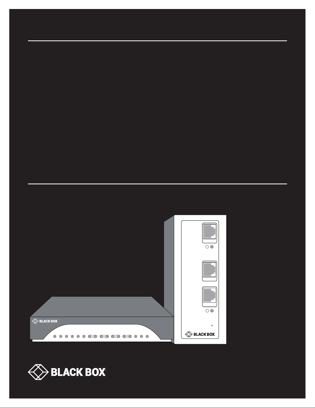
LB512A-KIT-R2, LB532A-L-R2, LB532A-R-R2, LB532A-M-R2
INDUSTRIAL
ETHERNET
EXTENDERS
24/7 TECHNICAL SUPPORT AT 1.877.877.2269 OR VISIT BLACKBOX.COM
Line
Eth 1
Eth 0
1 0
Power
ETH 3 ETH 2 ETH 1 ETH 0
Line 1
Line 2
Pwr
Reset
Page 2

NEED HELP?
LEAV E TH E TEC H TO US
LIVE 24/7
TABLE OF CONTENTS
TECHNICAL
SUPPORT
1. 8 7 7. 8 7 7. 2 2 69
SAFETY PRECAUTIONS .................................................................................................................................................................... 3
1. SPECIFICATIONS ........................................................................................................................................................................... 4
2. OV ERVIE W ...................................................................................................................................................................................... 5
2.1 Introduction ...............................................................................................................................................................................................5
2.2 What’s Included ........................................................................................................................................................................................5
2.3 Hardware Description ..............................................................................................................................................................................5
2.3.1 LB512A-R2 Front Panel .....................................................................................................................................................................................5
2.3.2 LB512A-R2 Back Panel ..................................................................................................................................................................................... 6
2.3.3 LB532A-R2 Front Panel ....................................................................................................................................................................................7
3. I N S TA LL AT ION .............................................................................................................................................................................. 8
3.1 Connect the Line Interface ......................................................................................................................................................................8
3.2 Connect the Ethernet Interface ...............................................................................................................................................................8
3.3 Connect the Power Source ...................................................................................................................................................................... 8
3.4 Status LEDs .............................................................................................................................................................................................. 9
4. CONFIGURATION ........................................................................................................................................................................ 10
4.1 Options .................................................................................................................................................................................................... 10
4.2 DIP Switches ........................................................................................................................................................................................... 11
5. WIZARD INTERFACE ................................................................................................................................................................... 12
5.1 Connect with Web GUI ........................................................................................................................................................................... 12
6. CLI OPERATION AND CONFIGURATION ................................................................................................................................... 16
6.1 Connect with SSH ................................................................................................................................................................................... 16
6.2 Change the IP Address ..........................................................................................................................................................................16
6.3 Change the Default Username ............................................................................................................ ..................................................16
6.4 Save the Configuration ..........................................................................................................................................................................16
6.5 DSL Commands ...................................................................................................................................................................................... 16
APPENDIX A. REGULATORY INFORMATION ................................................................................................................................ 19
A.1 EM C ......................................................................................................................................................................................................... 19
A.2 Safety ...................................................................................................................................................................................................... 19
A.3 PSTN Regulatory ...................................................................................................................................................................................19
A.4 FCC Part 68 (ACTA) Statement ............................................................................................................................................................ 19
A.5 Industry Canada Notice .........................................................................................................................................................................20
A.6 Radio and TV Interference (FCC Part 15) ............................................................................................................................................20
A.7 EC Declaration of Conformity ............................................................................................................ ...................................................20
APPENDIX B. DISCLAIMER/TRADEMARKS ................................................................................................................................. 21
B.1 Disclaimer ............................................................................................................................................................................................... 21
B.2 Trademarks Used in this Manual ............................................................................................................ ..............................................21
2
1. 87 7.8 7 7. 2 26 9 BLACKBOX.COM
Page 3

NEED HELP?
LEAV E TH E TEC H TO US
LIVE 24/7
SAFETY PRECAUTIONS
TECHNICAL
SUPPORT
1. 8 7 7. 8 7 7. 2 2 69
SAFETY PRECAUTIONS
WARNING: This device contains no user-serviceable parts. The equipment should be returned to Black Box for repairs, or repaired by a
qualified service personnel.
IMPORTANT: This is a Class A device and is intended for use in a light industrial environment. It is not intended nor approved for use in an
industrial or residential environment.
WARNING: The external power adapter should be a listed Limited Power Source. The outlet that is used to power the device should be
within 10 feet (3 meters) of the device, should be easily accessible, and protected by a circuit breaker.
If an AC power adapter is used, ensure that the power cable used meets all applicable standards for the country in which it is to be
installed, and that it is connected to a grounded wall outlet.
Hazardous network voltages are present in WAN ports regardless of whether power to the unit is ON or OFF. To avoid electric shock, use
caution when near WAN ports. When detaching the cables, detach the end away from the device first.
Do not work on the system or connect or disconnect cables during periods of lightning activity.
1. 87 7.8 7 7. 2 26 9 BLACKBOX.COM
3
Page 4

CHAPTER 1: SPECIFICATIONS
TABLE 1-1. SPECIFICATIONS
SPECIFICATION DESCRIPTION
Protocol
Transmission Line Single twisted pair (2-wire)
Line Rates
LED Status Indicators
Line Coding
Connectors
Line Interface Transformer coupled, 1500 VAC isolation
Management
MTBF 4.7 years
Power
Power Consumption
Operating Temperature
Humidity 5 to 95%, noncondensing
Altitude 0 to 15,000 ft. (0 to 4600 m)
Enclosure
Dimensions
Weight
Compliance FCC Part 15A, CE Mark per EMC directive 89/336/EEC, Low voltage directive 73/23/EEC
LB512A-KIT-R2, LB532A-L-R2, LB532A-R-R2: Transparent to higher layer protocols;
LB532A-M-R2: Transparent bridging (IEEE 802.1d), VLAN based QoS (802.1p/q), ARP, DHCP
LB512A-KIT-R2: 192 kbps to 5.7 Mbps, selectable in lal 64 kbps increments up to 5.7 Mbps;
LB532A-L-R2, LB532A-R-R2, LB532A-M-R2: 192 kbps to 15.3 Mbps, selectable in all 64 kbps increments starting at 192 kbps
WAN: Link;
LAN (Ethernet): Link/Act, Power
LB512A-KIT-R2: TC-PAM 16 for rates from 192 kbps to 2.3 Mbps; TC-PAM 32 for rates above 2.3 Mbps;
LB532A-L-R2, LB532A-R-R2: TC-PAM 16 for rates up to 2.3 Mbps; TC-PAM 32 for rates above 2.3 Mbps; |
TC-PAM 64 for rates up to 11.4 Mbps, TC-PAM 128 for rates up to 15.3 Mbps;
LB532A-M-R2: TC-PAM 16 for rates of 192 kbps to 2.3 Mbps; TC-PAM 32 for rates above 2.3 Mbps;
TC-PAM 64 for rates above 5.7 Mbps, TC-PAM 128 for rate sup to 11.4 Mbps
LB512A-KIT-R2: RJ-45 on copper line side and (4) 10/100 Ethernet, shrouded male IEC320 power connector;
LB532A-L-R2, LB532A-R-R2: RJ-45 on copper line side and (2) 10/100 Ethernet, terminal block power connector;
LB532A-M-R2: (2) RJ-45 on copper line side and (4) 10/100 Ethernet
LB512A-KIT-R2, LB532A-L-R2, LB532A-R-R2: DIP switch, Telnet console;
LB532A-M-R2: DIP switch, HTTP, NTP, SMPv3, SYSLOG Client, CLI (Telnet, SSH, Console port), TFTP firmware upgrade,
import/export config
LB512A-KIT-R2:
External: 90 to 260 VAC, 50 to 60 Hz (universal input);
LB532A-L-R2, LB532A-R-R2:
External: 90 to 260 VAC, 50 to 60 Hz (universal input);
Internal: 12 to +48 VDC (optional) (10 to 52 VDC);
LB532A-M-R2:
External: 90 to 260 VAC, 50 to 60 Hz (universal input) via terminal block;
Internal: +12 to +48 VDC (optional)
LB512A-KIT-R2, LB532A-L-R2, LB532A-R-R2: 0.8 A @ 5 V;
LB532A-M-R2: 1 A @ 5 V, 5 W
LB512A-KIT-R2: 32 to 122° F (0 to 55° F);
LB532A-L-R2, LB532A-R-R2, LB532A-M-R2: -40 to +185° F (-40 to +85° C)
LB512A-KIT-R2: Plastic;
LB532A-L-R2, LB532A-R-R2, LB532A-M-R2: Aluminum (IP40)
LB512A-KIT-R2: 1.52" H x 5" W x 4.7" D (3.9 x 12.7 x 10.6 cm);
LB532A-L-R2, LB532A-R-R2, LB532A-M-R2: 5.62" H x 2.25" W x 4.66" D (14.27 x 5.7 x 11.8 cm)
LB512A-KIT-R2: 2 lb. (1 kg);
LB532A-L-R2, LB532A-R-R2, LB532A-M-R2: 0.7 lb. (0.3 kg)
NEED HELP?
LEAV E TH E TEC H TO US
LIVE 24/7
TECHNICAL
SUPPORT
1. 8 7 7. 8 7 7. 2 2 69
4
1. 87 7.8 7 7. 2 26 9 BLACKBOX.COM
Page 5
NEED HELP?
LEAV E TH E TEC H TO US
LIVE 24/7
CHAPTER 2: OVERVIEW
TECHNICAL
SUPPORT
1. 8 7 7. 8 7 7. 2 2 69
2.1 INTRODUCTION
The Industrial Ethernet Extender is ideal for users or service providers who need high-speed dedicated network connections. Based
on the ITU and ETSI G.SHDSL G.991.2 standard, the LB512A-KIT-R2, LB532A-R2 enables providers to extend their reach-and-range by
delivering rate-adaptive nx64 symmetrical speeds up to 15.3 Mbps over a single pair of wires. If you need even more bandwidth, the
LB512A-KIT-R2, LB532A-R2 can bond as many as two pairs (4 wires) for up to 30 Mbps.
Below is a list of available products:
Industrial Ethernet Extender, consists of an Industrial Ethernet Extender, Local (LB532A-L-R2) and an Industrial Ethernet Extender,
Remote (LB532A-R-R2)
Industrial Ethernet Extender, Multidrop (LB532A-M-R2)
Ethernet Extender Kit (LB512A-KIT-R2), consists of a Local and a Remote Extender
2.2 WHAT’S INCLUDED
Your package should include the following items. If anything is missing or damaged, contact Black Box Technical Support at 877-877-2269
or [email protected]
LB512A-KIT-R2, LB532A-R2 Ethernet Extender, 4-Port
External power supply
2.3 HARDWARE DESCRIPTION
2.3.1 LB512A-R2 FRONT PANEL
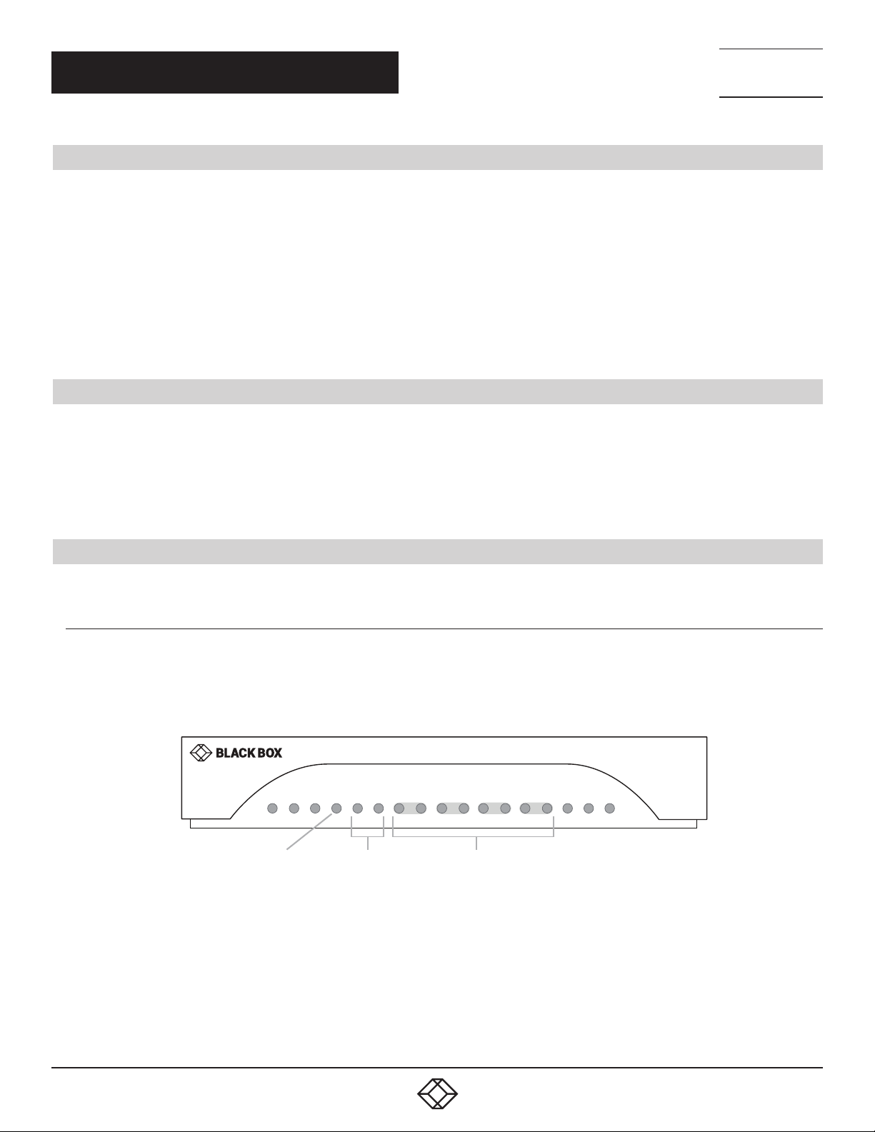
Figure 2-1 shows the front panel of the Ethernet Extender. Table 2-1 describes its components.
ETH 3 ETH 2 ETH 1 ETH 0
Line 1
Line 2
ETH3–ETH0
LEDs
Power
LED
Power
Line 1 & 2
LEDs
FIGURE 2-1. FRONT PANEL
1. 87 7.8 7 7. 2 26 9 BLACKBOX.COM
5
Page 6
CHAPTER 2: OVERVIEW
TABLE 2-1. FRONT PANEL COMPONENTS
COMPONENT IN FI GU RE 2-1 DESCRIPTION
Power LED
Line 1 and Line 2 LEDs
ETH3–ETH0 LEDs
2.3.2 LB512A-R2 BACK PANEL
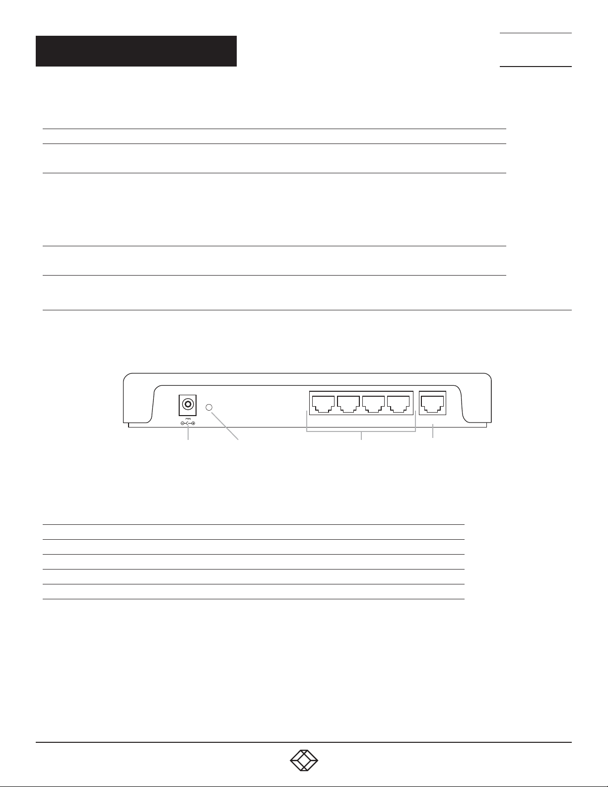
Figure 2-2 shows the back panel of the Ethernet Extender. Table 2-2 describes its components.
LED turns on when power is supplied to the unit.
LED is off when no power is supplied to the unit.
One LED for each port.
OFF = Port is configured as down.
ON = Port is in data mode.
Blinking slowly = Port is in handshake mode (looking for a remote signal)
Blinking fast - Port is in training mode (active communication with remote)
ON = Port is linked
OFF = Data is passing over the port
NEED HELP?
LEAV E TH E TEC H TO US
LIVE 24/7
TECHNICAL
SUPPORT
1. 8 7 7. 8 7 7. 2 2 69
Reset
5V 1A
Power Reset Button Ethernet Ports
FIGURE 2-2. BACK PANEL
TABLE 2-2. BACK PANEL COMPONENTS
COMPONENT IN FIGURE 2-2 DESCRIPTION
Barrel connector Links to 5-V, 1-A external power supply
Reset button Press to reset the unit
(4) RJ-45 connectors Ethernet ports (0/3 - 0/0)
(1) RJ-45 connector Line port
Eth3 Eth2 Eth1 Eth0 Line
Line Port
(0/3–0/0)
6
1. 87 7.8 7 7. 2 26 9 BLACKBOX.COM
Page 7
CHAPTER 2: OVERVIEW
2.3.3 LB532A-R2 FRONT PANEL
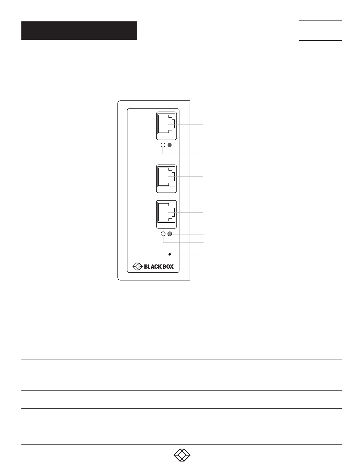
Figure 2-3 shows the front panel of the Ethernet Extender. Table 2-1 describes its components.
Line Port
Line
Pwr
Pwr (Power) LED
Line Link LED
Eth 1 (Ethernet Port 1)
NEED HELP?
LEAV E TH E TEC H TO US
LIVE 24/7
TECHNICAL
SUPPORT
1. 8 7 7. 8 7 7. 2 2 69
Eth 1
Eth 0 (Ethernet Port 0)
Eth 0
Ethernet Port 0 Link LED
Ethernet Port 1 Link LED
Reset button
FIGURE 2-3. LB532A-R2 FRONT PANEL
TABLE 2-3. LB532A-R2 FRONT PANEL COMPONENTS
COMPONENT IN FI GU RE 2-3 DESCRIPTION
RJ-45 connector Line Port
Power LED Lights when power is ON to the unit
Line Link LED The Link LED glows solid while a link is established. While the link is training, it blinks once every second.
Eth 1 (Ethernet Port 1)
Eth 0 (Ethernet Port 0)
Ethernet Port 0 Link LED
Ethernet Port 1 Link LED
Reset button Press to reset the unit
The Ethernet Link LED shows that there is an active physical connection to the console, or an active physical
connection to an Ethernet device.
The Ethernet Link LED shows that there is an a=ctive physical connection to the console, or an active physical
connection to an Ethernet device.
ON = Port is linked
OFF = Data is passing over the port
ON = Port is linked
OFF = Data is passing over the port
1. 87 7.8 7 7. 2 26 9 BLACKBOX.COM
7
Page 8
NEED HELP?
LEAV E TH E TEC H TO US
LIVE 24/7
CH APTER 3: I NSTALLATION
3.1 CONNECT THE LINE INTERFACE
To function properly, the LB512A-KIT-R2, LB532A-R2 must be connected using a twisted-pair, unconditioned, dry, metal wire, between 19
(0.9 - mm)
and 26 AWG (0.4-mm). Leased circuits that run through signal equalization equipment are not acceptable.
The Ethernet Extender has an RJ-45 interface jack (DSL) that conforms to the T568B standard. Any standard Category 5e cable
can be used to directly connect two extenders. The Ethernet Extender has a two-wire interface.
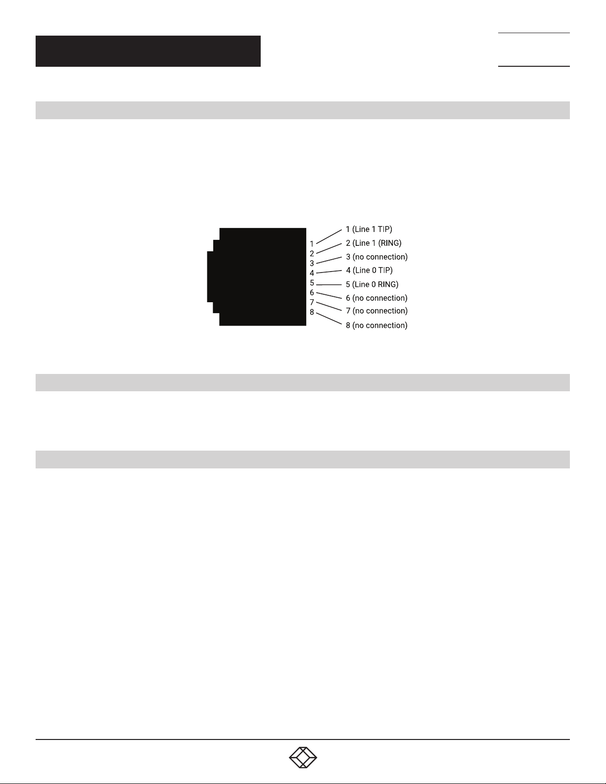
Observe the signal/pin relationship on the LB512A-KIT-R2, LB532A-R2’s Line interface jack for each pair in Figure 3-1.
TECHNICAL
SUPPORT
1. 8 7 7. 8 7 7. 2 2 69
FIGURE 3-1. RJ-45 TWISTED-PAIR LINE INTERFACE
3.2 CONNECT THE ETHERNET INTERFACE
The Ethernet Extender has four unshielded RJ-45 auto-MDIX 10/100BASE-T interfaces. These are designed to connect directly
to a 10/100BASE-TX network. You may connect this port to a hub or PC using a straight-through or crossover cable that is
up to 328 feet (100 meters) long.
3.3 CONNECT THE POWER SOURCE
The Ethernet Extender does not have a power switch, so it powers up as soon as it is plugged in.
Connect the power via the barrel jack on the rear panel of the Extender. No configuration is necessary for the power supply.
8
1. 87 7.8 7 7. 2 26 9 BLACKBOX.COM
Page 9
CH APTER 3: I NSTALLATION
3.4 STATUS LEDS
The LEDs indicate the status of power, copper link, and Ethernet connections.
NOTE: When off, the LED indicators are clear; when lit, the indicators are yellow.
TABLE 3-1. FRONT PANEL LEDS
NUMBE R IN FIGU RE 2-1 LED INDICATOR DESCRIPTION
1 Power LED
2 On-site Pair LEDs
3 ETH3–ETH0 LEDs
LED turns on when power is supplied to the unit.
LED is off when no power is supplied to the unit.
One LED for each port.
OFF = Port is configured as down.
ON = Port is in data mode.
Blinking slowly = Port is in handshake mode (looking for a remote signal)
Blinking fast - Port is in training mode (active communication with remote)
ON = Port is linked
OFF = Data is passing over the port
NEED HELP?
LEAV E TH E TEC H TO US
LIVE 24/7
TECHNICAL
SUPPORT
1. 8 7 7. 8 7 7. 2 2 69
1. 87 7.8 7 7. 2 26 9 BLACKBOX.COM
9
Page 10

NEED HELP?
LEAV E TH E TEC H TO US
LIVE 24/7
CHAPTER 4: CONFIGURATION
4.1 OPTIONS
The copper-link extenders are configured to work in pairs. If the factory-installed configuration needs to be adjusted, you can configure the
device by using:
DIP switches (while powered off)
Web Wizards through HTTP access
Command line interface (CLI) through SSH
A combination of the above
For simple and common configurations, you may only need to use the DIP switches.
NOTE: If you will not have physical access to the device, it is best to leave the DIP switches disabled, as they will always override the other
configuration access methods for some settings. This will be problematic if you need to change these settings remotely.
The factory installed configuration is shown below.
TECHNICAL
SUPPORT
1. 8 7 7. 8 7 7. 2 2 69
context ip ROUTER
interface LAN
ipaddress 192.168.200.11/24 #Remote units are set to 192.168.200.10/24
ipaddress DHCP dhcp
context switch-group DEFAULT
bind interface ROUTER LAN
no shutdown
interface ETHERNET _ 0 _ 0
interface ETHERNET _ 0 _ 1
interface ETHERNET _ 0 _ 2
interface ETHERNET _ 0 _ 3
interface DSL _ 0 _ 0
port ethernet 0 0
bind switch-group DEFAULT ETHERNET _ 0 _ 0
no shutdown
port ethernet 0 1
bind switch-group DEFAULT ETHERNET _ 0 _ 1
no shutdown
port ethernet 0 2
bind switch-group DEFAULT ETHERNET _ 0 _ 2
no shutdown
port ethernet 0 3
bind switch-group DEFAULT ETHERNET _ 0 _ 3
no shutdown
port line 0 0
service-mode 2-wire
mode local
bind switch-group DEFAULT DSL _ 0 _ 0
no shutdown
10
1. 87 7.8 7 7. 2 26 9 BLACKBOX.COM
Page 11

NEED HELP?
LEAV E TH E TEC H TO US
LIVE 24/7
CHAPTER 4: CONFIGURATION
4.2 DIP SWITCHES
The DIP switches enable you to configure the Local/Remote and TCPAM/Rate preset. These settings are applied when the device powers
on, and they cannot be changed while the device is powered on. Keep this in mind if you plan on adjusting these settings later remotely, as
the DIP switch settings at boot will always take priority.
To disable the DIP switches:
1. Power off the device.
2. Set all DIP switches to OFF.
To enable the DIP switches:
1. Power off the device.
2. Set DIP switch #1 to Local or Remote. When connecting two Ethernet Extenders, one needs to be configured as Local, and the other
Remote:
OFF = Local
ON = Remote
3. Set DIP switches #2–5 to a TCPAM/Rate Preset. When connecting two Ethernet Extenders back to back, their speeds should be
configured to match.
4. Set DIP switches #6–8 to OFF. These are reserved for future use.
TECHNICAL
SUPPORT
1. 8 7 7. 8 7 7. 2 2 69
TABLE 4-1. DIP SWITCHES
#2 #3 #4 #5 TCPAM/R ATE PRESET
ON ON ON ON TCPAM 16/32 Autorate
ON ON ON OFF TCPAM 6 4/128 Autorate
ON ON OFF ON TCPAM-4 192 kbps
ON ON OFF OFF TCPAM-4 2496 kbps
ON OFF ON ON TCPAM-8 192 kbps
ON OFF ON OFF TCPAM-8 5056 kbps
ON OFF OFF ON TCPAM-16 192 kbps
ON OFF OFF OFF TCPAM-16 3840 kbps
OFF ON ON ON TCPAM-32 768 kbps
OFF ON ON OFF TCPAM-32 5696 kbps
OFF ON OFF ON TCPAM-64 192 kbps
OFF ON OFF OFF TCPAM-64 12736 kbps
OFF OFF ON ON TCPAM-128 256 kbps
OFF OFF ON OFF TCPAM-128 15296 kbps
OFF OFF OFF ON Reserved
OFF OFF OFF OFF Disable DIP switches
1. 87 7.8 7 7. 2 26 9 BLACKBOX.COM
11
Page 12
NEED HELP?
LEAV E TH E TEC H TO US
LIVE 24/7
CHAPTER 5: WIZARD INTERFACE
The Ethernet Extender provides a browser interface that allows you to configure and manage it. After you set up the IP address for the
extender, you can access the Web interface applications directly in your Web browser by entering the configured IP address. You can
then use your Web browser to list and manage configuration parameters from a PC.
NOTE: Earlier versions predating Internet Explorer 9.0 browser are not compatible with the LB512A-KIT-R2, LB532A-R2.
5.1 CONNECT WITH WEB GUI
1. Connect the Ethernet cable.
2. Connect the power supply.
3. Connect via web browser to the default address 192.168.200.10 or connect to 192.168.200.11 for 2-pack local units.
4. Log in with the default username admin without a password.
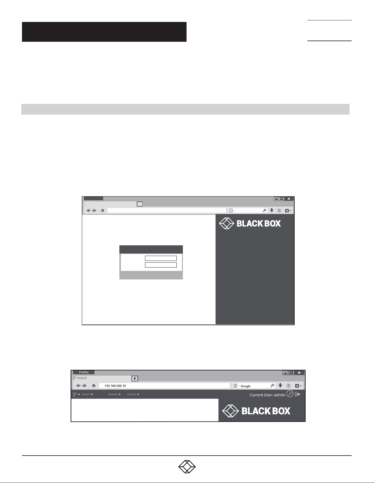
Once the network connection is established, you will be able to reach the LB512A-KIT-R2, LB532A-R2 Web GUI. Log into the Web GUI
using the following credentials (see Figure 5-1).
username: admin
password: [blank, just press the Enter key]
TECHNICAL
SUPPORT
1. 8 7 7. 8 7 7. 2 2 69
Firefox
WebUI
P
192.168.200.10
Login
User Name:
Password:
+
Google
admin
Login
Model:
Model Description:
System Description
Release Version:
Release Date:
Box Status;
Active Alarms
LB532A-R2
CopperLink Ethernet Extender
3.4.0
2013/11/25
Operational
0
FIGURE 5-1. LOGIN SCREEN
The LB512A-KIT-R2, LB532A-R2 includes a Web Wizard within the GUI. The Icon to the wizard is in the top right corner of your browser
as shown in Figure 5-2.
12
FIGURE 5-2. WEB WIZARD HOME PAGE
1. 87 7.8 7 7. 2 26 9 BLACKBOX.COM
Page 13
NEED HELP?
LEAV E TH E TEC H TO US
LIVE 24/7
CHAPTER 5: WIZARD INTERFACE
TECHNICAL
SUPPORT
1. 8 7 7. 8 7 7. 2 2 69
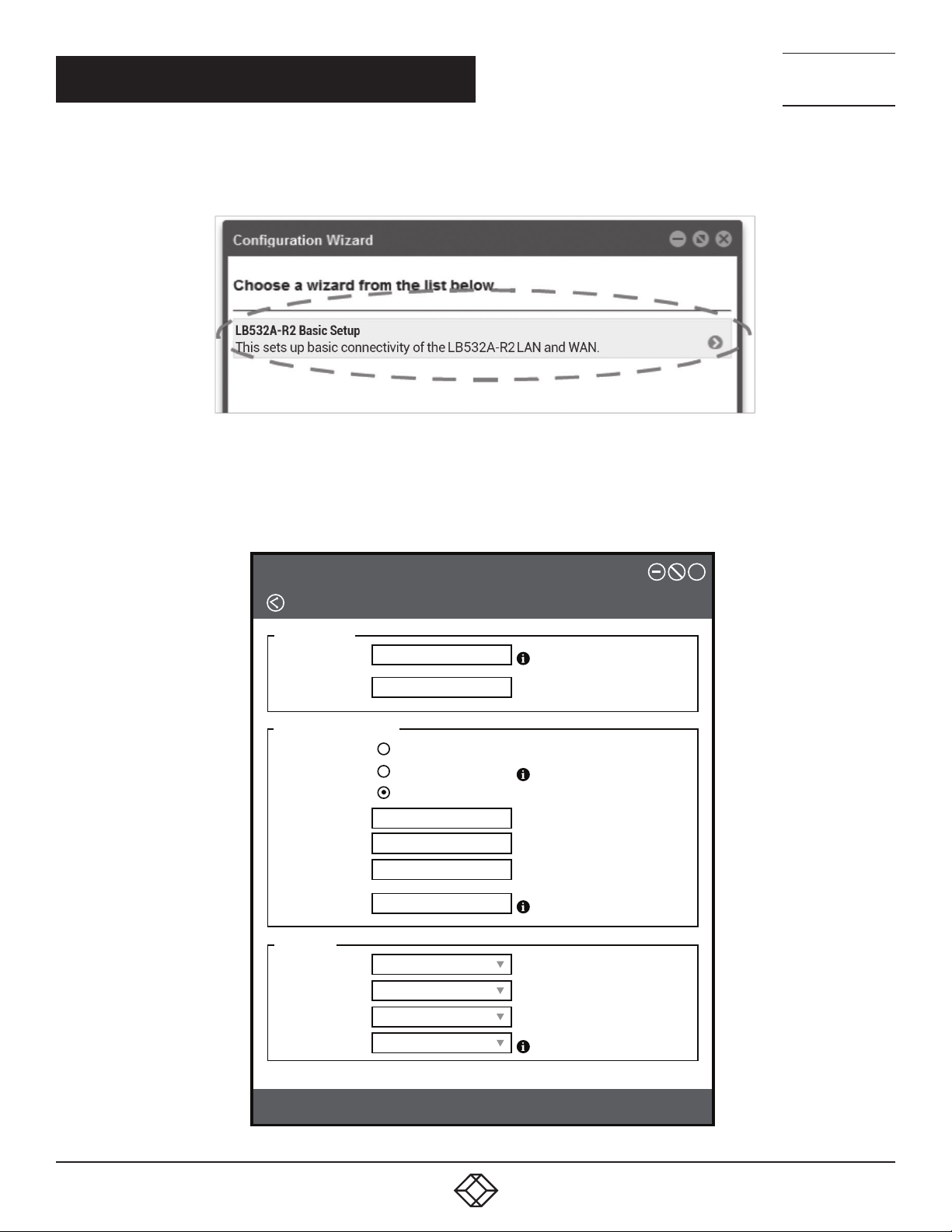
Once the wizard icon is selected, you will have the options of supported set-ups as shown in Figure 5-3. Click on LB512A-KIT-R2,
LB532A-R2 Basic Setup.
FIGURE 5-3. CHOOSE WIZARD
Clicking on the LB512A-KIT-R2, LB532A-R2 Basic Setup will bring up the most common configurations used on the Ethernet Extender.
Figure 5-4 depicts options to configure the extender through the Basic Setup wizard.
Configuration Wizard
LB532A-R2
User Address
Password:
Retype
Password:
Management IP Setup
Management IP:
IP Address:
Netmask:
Gateway:
Management
VLAN ID:
Line Setup
Line Type:
Service Mode:
Annex:
Static
DHCP
Both
192 168 200 10
255 255 255 0
Local
2 wire
B/G
NormalLine Rate:
X
Preview
FIGURE 5-4. BASIC SETUP
1. 87 7.8 7 7. 2 26 9 BLACKBOX.COM
Save & Reboot
13
Page 14
NEED HELP?
LEAV E TH E TEC H TO US
LIVE 24/7
CHAPTER 5: WIZARD INTERFACE
User Access: (optional configuration) Users may change the password for the admin user.
Management IP Setup:
- Static: Create your own IP address, netmask and gateway (optional–the gateway is required for remote management).
- DHCP: The LB512A-KIT-R2, LB532A-R2 management port will accept an IP address from a DHCP server.
- Both: This choice will assign two IP addresses (one static and one DHCP to the management port
- Management VLAN ID: (Optional) define a VLAN ID for management traffic.
Line Setup: This where you can manually set your copper link line options.
NOTE: The copper link Ethernet Extenders by default are set to plug-and-play operation.
- Line Type (Local or Remote): This will set the extender as Local or Remote. Local is typically used at the network, Remote is typically used at
the remote device or remote network. LB512A-KIT-R2 is already configured as one Local and one Remote.
- Service Mode: Configures the number of pairs (wires) you want to use. The extender will default to the maximum number of wires available
on your Extender (2-wire).
- Annex: Consult Black Box Technical Support at 877-877-2269 or [email protected] before changing this setting.
- Line Rate Configuration: This will increase the potential line rate of the extender. The extender defaults to automatically select the optimal
rate based on the distance (adaptive).
NOTE: There are two modes: Normal (TCPAM16|32) and Extended (TCPAM64|128). Selecting the Extended mode will double the
bandwidth, but will reduce the reach (distance) by half. Default is normal.
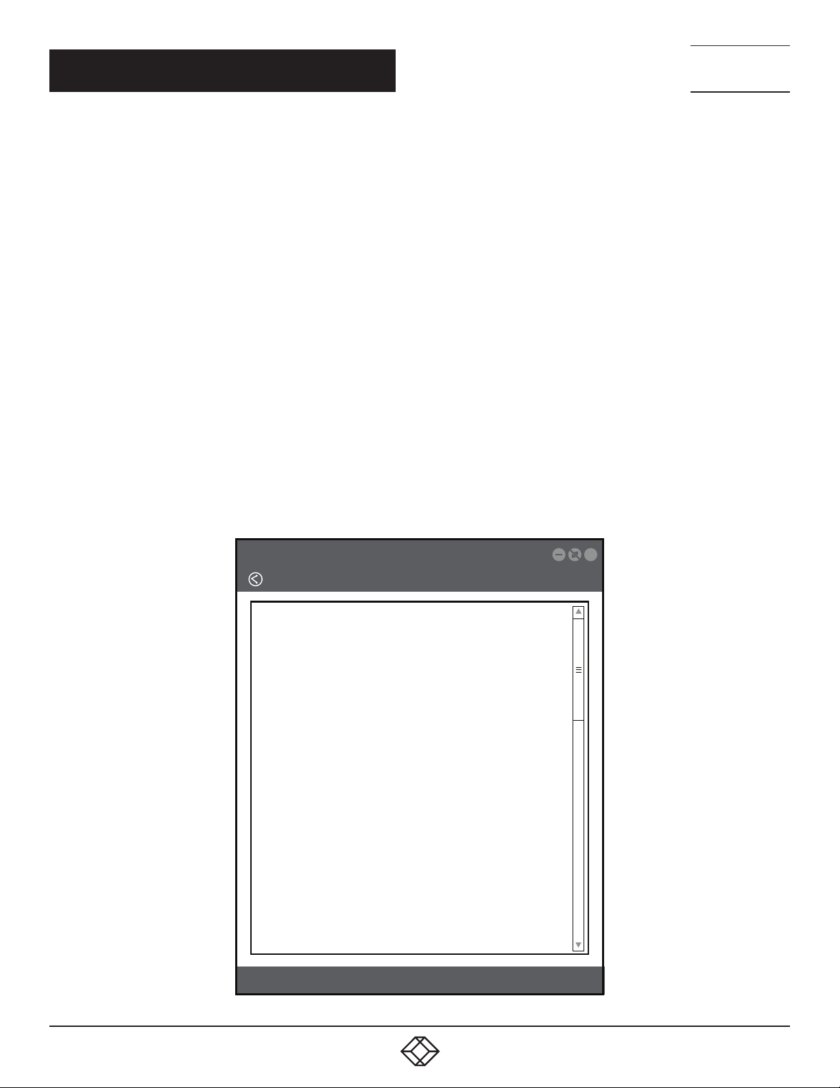
On the bottom right corner of the Basic Configuration wizard page, you can preview configurations and reboot. Figure 8 depicts what you
can expect to see if you click on the preview tab.
TECHNICAL
SUPPORT
1. 8 7 7. 8 7 7. 2 2 69
Configuration Wizard
Configuratinon Preview
#Black Box Corporation
#This is a generated configuration from the following Wizard
#LB532A-R2 Basic Setup
# This sets up basic connectivity of the LB532A-R2 LAN and WAN.
# - -- - - - - - - - - - - - - - - - - - - - - - - - - - - - - -
cli vbersion 4.0
snmp shutdown
profile aaa DEFAULT
method 1 local rule sufficient
console
use profile aaa DEFAULT
telnet-server
use profile aaa DEFAULT
shutdown
sss-server
use profile aaa DEFAULT
no shutdown
web-server http
use profile aaa DEFAULT
no shutdown
web-server https
use profile aaa DEFAULT
X
14
Save & Reboot
FIGURE 5-5. CONFIGURE PREVIEW OPTION
1. 87 7.8 7 7. 2 26 9 BLACKBOX.COM
Page 15
NEED HELP?
LEAV E TH E TEC H TO US
LIVE 24/7
CHAPTER 5: WIZARD INTERFACE
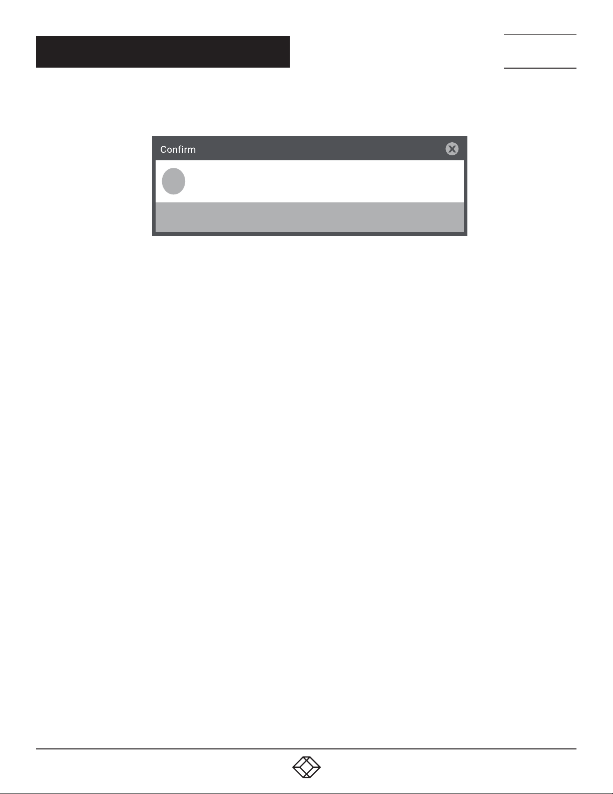
When you choose the save and reboot option, a prompt will ask you to confirm. If the configuration is correct, select Yes as shown
in Figure 5-6.
TECHNICAL
SUPPORT
1. 8 7 7. 8 7 7. 2 2 69
Confirm
?
Are you sure you want to apply the generated config and reboot?
Yes
FIGURE 5-6. CONFIRMATION SCREEN
Typically the time to reboot and re-establish a DSL link so the extender can pass traffic will be less than 2 minutes.
No
1. 87 7.8 7 7. 2 26 9 BLACKBOX.COM
15
Page 16

CHAPTER 6: CLI OPERATION AND CONFIGURATION
You can connect a PC to configure the LB512A-KIT-R2, LB532A-R2 Ethernet Extender using the CLI.
6.1 CONNECT WITH SSH
1. Connect the Ethernet cable.
2. Connect the power supply.
3. Connect via SSH to the extender through its IP address:
– Default remote IP address: 192.168.200.10
– Default local IP address: 192.168.200.11
4. Login with the default username admin and no password.
6.2 CHANGE THE IP ADDRESS (DEFAULT: 192.168.200.10)
Follow the command sequence below.
node~>enable
node~#configure node~(cfg)#context ip router
node~(ctx-ip)[router]#interface LA N
node~(if-ip)[router.LAN]#no ipaddress 192.168.200.10/24
node~(if-ip)[router.LAN]#ipaddress <new address>/<new mask>
NEED HELP?
LEAV E TH E TEC H TO US
LIVE 24/7
TECHNICAL
SUPPORT
1. 8 7 7. 8 7 7. 2 2 69
6.3 CHANGE THE DEFAULT USERNAME
The default username will be removed once a new one is created. Follow the command sequence below:
node~>enable
node~#configure
node~(cfg)#superuser <username> password <password>
6.4 SAVE THE CONFIGURATION
Follow the command sequence below:
node~>enable
node~#configure
node~(cfg)#copy running-config startup-config
6.5 COPPER LINK LINE COMMANDS
LOCAL AND REMOTE
This will set the extender as Local or Remote. Local is typically used at the network, Remote is typically used at the remote device or
remote network. LB512A-KIT-R2 is already configured one as Local and one as Remote.
node(cfg)# mode {local|remote}
16
1. 87 7.8 7 7. 2 26 9 BLACKBOX.COM
Page 17

NEED HELP?
LEAV E TH E TEC H TO US
LIVE 24/7
CHAPTER 6: CLI OPERATION AND CONFIGURATION
TECHNICAL
SUPPORT
1. 8 7 7. 8 7 7. 2 2 69
ANNEX TYPE
Consult Black Box Technical Support at 877-877-2269 or [email protected] before changing this setting.
node(prt-dsl)[0/0]# annex-type { b-g | a-f }
LINE RATE CONFIGURATION
This will increase the line rate of the extender. Your extender defaults to auto-matically select the optimal rate based on the distance
(adaptive).
node(prt-dsl)[0/0]# payload-rate {adaptive [max <192..15296>] | <192..15296>}
MODULATION SCHEME
NOTE: Higher TC-PAM rates will increase maximum payload rates available, but will decrease distance. Your extender defaults to
automatically select the optimal setting. Consult the rate reach chart to determine your optimal setting if you choose to hard-set this
value. Higher TC-PAM rates are ideal for shorter cable runs offering max symmetrical (upstream/downstream) speeds of 11.4 Mbps
(TCPAM64) and 15.3 Mbps (TCPAM128) per pair.
node(prt-line)[0/0]# tcpam {auto(16/32) | auto(64/128) | 16 | 32 | 64 | 128}
COPPER LINK PORTS
The configurations below are used to configure various aspects of the copper link port(s).
node(cfg)# port dsl 0 0
SIGNAL TO NOISE RATIO
Configures the acceptable noise margin for adaptive rate. SNR is the relative strength of the DSL signal to Noise ratio. 6 dB is generally
the lowest dB recommended in order for the modem to be able to synch. Generally speaking, as overall bandwidth increases, your signal
to noise ratio decreases. The higher the number the better. Your extender defaults to 6, giving you the highest likelihood to connect.
no de(prt-dsl)[0/0]# snr-m argin <-10..22>
Below 6 dB bad
6 dB–10 dB fair
11dB–20 dB good
DESCRIPTION
This is the description of the port/line (copper link connection). (Ex: "This line goes to building 4") When entering a description with
spaces in the text, the description must be in quotations.
node~(prt-dsl)[0/0]# description <description>
SERVICE MODE
Configures the number of pairs (wires) you want to use. The LB512A-KIT-R2, LB532A-R2 will default to the maximum number of wires
available on your version of the G.SHDSL.bis CPE: LB512A-KIT-R2, LB532A-R2 (4-wire).
node~(prt-dsl)[0/0]# service-mode { 2-wire | 4-wire }
1. 87 7.8 7 7. 2 26 9 BLACKBOX.COM
17
Page 18

CHAPTER 6: CLI OPERATION AND CONFIGURATION
SHUTDOWN
Disables or enables copper link port(s).
node~(prt-line)[0/0]# [no] shutdown
EXIT
Goes back to parent mode.
node~(prt-line)[0/0]# exit
SHOW
Displays all the configured options of the LB510A-R2 copper link port(s)
node(cfg)# show port line 0 0
NEED HELP?
LEAV E TH E TEC H TO US
LIVE 24/7
TECHNICAL
SUPPORT
1. 8 7 7. 8 7 7. 2 2 69
18
1. 87 7.8 7 7. 2 26 9 BLACKBOX.COM
Page 19

APPENDIX A: REGULATORY INFORMATION
A .1 E M C
FCC Part 15, Class A
EN55022, Class A
EN55024
A.2 SAFETY
UL 60950-1/CSA C22.2 N0. 60950-1
IEC/EN60950-1
AS/NZS 60950-1
NEED HELP?
LEAV E TH E TEC H TO US
LIVE 24/7
TECHNICAL
SUPPORT
1. 8 7 7. 8 7 7. 2 2 69
A.3 PSTN REGULATORY
FCC Part 68
CS-03
AS/ACIF S043:2003
A.4 FCC PART 68 (ACTA) STATEMENT
This equipment complies with Part 68 of FCC rules and the requirements adopted by ACTA. On the bottom side of this equipment is a
label that contains—among other information—a product identifier in the format US: A AAEQ##TXXXX. If requested, this number must be
provided to the telephone company.
The method used to connect this equipment to the premises wiring and telephone net-work must comply with the applicable FCC Part 68
rules and requirements adopted by the ACTA.
If this equipment causes harm to the telephone network, the telephone company will notify you in advance that temporary
discontinuance of service may be required. But if advance notice isn’t practical, the telephone company will notify the customer as soon
as possible. Also, you will be advised of your right to file a complaint withthe FCC if you believe it is necessary.
The telephone company may make changes in its facilities, equipment, operations or procedures that could affect the operation of the
equipment. If this happens the tele-phone company will provide advance notice in order for you to make necessary modifications to
maintain uninterrupted service.
If trouble is experienced with this equipment, for repair or warranty information, please contact our company. If the equipment is causing
harm to the telephone network, the telephone company may request that you disconnect the equipment until the problem is resolved.
Connection to party line service is subject to state tariffs. Contact the state public utility commission, public service commission or
corporation commission for information.
1. 87 7.8 7 7. 2 26 9 BLACKBOX.COM
19
Page 20

NEED HELP?
LEAV E TH E TEC H TO US
LIVE 24/7
APPENDIX A: REGULATORY INFORMATION
TECHNICAL
SUPPORT
1. 8 7 7. 8 7 7. 2 2 69
A.5 INDUSTRY CANADA NOTICE
This equipment meets the applicable Industry Canada Terminal Equipment Technical Specifications. This is confirmed by the registration
number. The abbreviation, IC, before the registration number signifies that registration was performed based on a Declaration of
Conformity indicating that Industry Canada technical specifications were met. It does not imply that Industry Canada approved the
equipment.
This Declaration of Conformity means that the equipment meets certain telecommuni-cations network protective, operational and safety
requirements. The Department does not guarantee the equipment will operate to the user's satisfaction. Before installing this equipment,
users should ensure that it is permissible to be connected to the facili-ties of the local telecommunications company. The equipment
must also be installed using an acceptable method of connection. In some cases, the company’s inside wiring associated with a single
line individual service may be extended by means of a certified connector assembly (telephone extension cord). The customer should
be aware that compliance with the above condition may not prevent degradation of service in some situations. Repairs to some certified
equipment should be made by an authorized main-tenance facility designated by the supplier. Any repairs or alterations made by the user
to this equipment, or equipment malfunctions, may give the telecommunications com-pany cause to request the user to disconnect the
equipment. Users should ensure for their own protection that the ground connections of the power utility, telephone lines and internal
metallic water pipe system, are connected together. This protection may be particularly important in rural areas.
A.6 RADIO AND TV INTERFERENCE (FCC PART 15)
This equipment generates and uses radio frequency energy, and if not installed and used properly—that is, in strict accordance with the
manufacturer's instructions— may cause interference to radio and television reception. This equipment has been tested and found to
comply with the limits for a Class A computing device in accordance with the specifications in Subpart B of Part 15 of FCC rules, which
are designed to provide reasonable protection from such interference in a commercial installation. However, there is no guarantee that
interference will not occur in a particular installation. If the equipment causes interference to radio or television reception, which can be
determined by disconnecting the cables, try to correct the interference by one or more of the following measures: moving the computing
equip-ment away from the receiver, re-orienting the receiving antenna, and/or plugging the receiving equipment into a different AC outlet
(such that the computing equipment and receiver are on different branches).
A.7 EC DECLARATION OF CONFORMITY
We certify that the apparatus identified above conforms to the requirements of Council Directive 1999/5/EC on the approximation of the
laws of the member states relating to Radio and Telecommunication Terminal Equipment and the mutual recognition of their conformity.
The safety advice in the documentation accompanying the products shall be obeyed. The conformity to the above directive is indicated
by the CE sign on the device.
In accordance with the requirements of council directive 2002/96/ EC on Waste of Electrical and Electronic Equipment (WEEE), ensure
that at end-of-life you separate this product from other waste and scrap and deliver to the WEEE collection system in your country for
recycling.
20
1. 87 7.8 7 7. 2 26 9 BLACKBOX.COM
Page 21

NEED HELP?
LEAV E TH E TEC H TO US
LIVE 24/7
APPENDIX B: DISCLAIMER/TRADEMARKS
TECHNICAL
SUPPORT
1. 8 7 7. 8 7 7. 2 2 69
B.1 DISCLAIMER
Black Box Corporation shall not be liable for damages of any kind, including, but not limited to, punitive, consequential or cost of cover
damages, resulting from any errors in the product information or specifications set forth in this document and Black Box Corporation
may revise this document at any time without notice.
B.2 TRADEMARKS USED IN THIS MANUAL
Black Box and the Black Box logo type and mark are registered trademarks of Black Box Corporation.
Any other trademarks mentioned in this manual are acknowledged to be the property of the trademark owners.
1. 87 7.8 7 7. 2 26 9 BLACKBOX.COM
21
Page 22

NOTES
__________________________________________________________________________________________________
__________________________________________________________________________________________________
__________________________________________________________________________________________________
__________________________________________________________________________________________________
__________________________________________________________________________________________________
_
_________________________________________________________________________________________________
NEED HELP?
LEAV E TH E TEC H TO US
LIVE 24/7
TECHNICAL
SUPPORT
1. 8 7 7. 8 7 7. 2 2 69
__________________________________________________________________________________________________
__________________________________________________________________________________________________\
__________________________________________________________________________________________________
__________________________________________________________________________________________________
__________________________________________________________________________________________________
__________________________________________________________________________________________________
________________________________________________________________________________________________
__________________________________________________________________________________________________
__________________________________________________________________________________________________
22
__________________________________________________________________________________________________
__________________________________________________________________________________________________
__________________________________________________________________________________________________
1. 87 7.8 7 7. 2 26 9 BLACKBOX.COM
Page 23

NOTES
_
_________________________________________________________________________________________________
__________________________________________________________________________________________________
__________________________________________________________________________________________________\
__________________________________________________________________________________________________
__________________________________________________________________________________________________
__________________________________________________________________________________________________
NEED HELP?
LEAV E TH E TEC H TO US
LIVE 24/7
TECHNICAL
SUPPORT
1. 8 7 7. 8 7 7. 2 2 69
__________________________________________________________________________________________________
________________________________________________________________________________________________
_______________________________________________________________________________________________
__________________________________________________________________________________________________
__________________________________________________________________________________________________\
__________________________________________________________________________________________________
__________________________________________________________________________________________________
__________________________________________________________________________________________________
__________________________________________________________________________________________________
________________________________________________________________________________________________
__________________________________________________________________________________________________
__
1. 87 7.8 7 7. 2 26 9 BLACKBOX.COM
23
Page 24

NEED HELP?
LEAVE THE TECH TO US
LIVE 24/7
TECHNICAL
SUPPORT
1.87 7. 877.2 269
© COPYRIGHT 2018. BLACK BOX CORPORATION. ALL RIGHTS RESERVED.
LB512A-KIT-R2_LB532A-R2_USER_REV1.PDF
 Loading...