

Page 1

1000 Park Drive • Lawrence, PA 15055-1018 • 724-746-5500 • Fax 724-746-0746
© Copyright 1996. Black Box Corporation. All rights reserved.
Page 2
Order toll-free in the U.S. 24 hours, 7 A.M. Monday to midnight Friday: 877-877-BBOX
FREE technical support, 24 hours a day, 7 days a week: Call 724-746-5500 or fax 724-746-0746
Mail order: Black Box Corporation, 1000 Park Drive, Lawrence, PA 15055-1018
Web site: www.blackbox.com • E-mail: info@blackbox.com
CUSTOMER
SUPPORT
INFORMATION
AUGUST 1996
LB5000A
Ethernet to Token Ring Bridge
PO
W
ER
S
TA
TU
S
PW
R
C
O
N
T
R
O
L
P
O
R
T
EthernetTo Token R
ing B
ridge
ETH
ER
N
ET
H
S
N
T
O
K
E
N
R
IN
G
OK
COL
TxD
RxD
DSR
DTR
TxD
RxD
Page 3

FEDERAL COMMUNICATIONS COMMISSION
AND
INDUSTRY CANADA
RADIO FREQUENCY INTERFERENCE STATEMENTS
This equipment generates, uses, and can radiate radio frequency energy and if not installed and used properly, that is, in
strict accordance with the manufacturer’s instructions, may cause interference to radio communication. It has been tested
and found to comply with the limits for a Class A computing device in accordance with the specifications in Subpart J of
Part 15 of FCC rules, which are designed to provide reasonable protection against such interference when the equipment is
operated in a commercial environment. Operation of this equipment in a residential area is likely to cause interference, in
which case the user at his own expense will be required to take whatever measures may be necessary to correct the
interference.
Changes or modifications not expressly approved by the party responsible for compliance could void the user’s authority to
operate the equipment.
This digital apparatus does not exceed the Class A limits for radio noise emission from digital apparatus set out in the Radio Interference
Regulation of Industry Canada.
Le présent appareil numérique n’émet pas de bruits radioélectriques dépassant les limites applicables aux appareils numériques de
classe A prescrites dans le Règlement sur le brouillage radioélectrique publié par Industrie Canada.
INSTRUCCIONES DE SEGURIDAD (Normas Oficiales Mexicanas Electrical Safety Statement)
1. Todas las instrucciones de seguridad y operación
deberán ser leídas antes de que el aparato eléctrico sea
operado.
2. Las instrucciones de seguridad y operación deberán ser
guardadas para referencia futura.
3. Todas las advertencias en el aparato eléctrico y en sus
instrucciones de operación deben ser respetadas.
4. Todas las instrucciones de operación y uso deben ser
seguidas.
5. El aparato eléctrico no deberá ser usado cerca del
agua—por ejemplo, cerca de la tina de baño, lavabo,
sótano mojado o cerca de una alberca, etc.
6. El aparato eléctrico debe ser usado únicamente con
carritos o pedestales que sean recomendados por el
fabricante.
7. El aparato eléctrico debe ser montado a la pared o al
techo sólo como sea recomendado por el fabricante.
8. Servicio—El usuario no debe intentar dar servicio al
equipo eléctrico más allá a lo descrito en las
instrucciones de operación. Todo otro servicio deberá
ser referido a personal de servicio calificado.
9. El aparato eléctrico debe ser situado de tal manera que
su posición no interfiera su uso. La colocación del
aparato eléctrico sobre una cama, sofá, alfombra o
superficie similar puede bloquea la ventilación, no se
debe colocar en libreros o gabinetes que impidan el
flujo de aire por los orificios de ventilación.
10. El equipo eléctrico deber ser situado fuera del alcance
de fuentes de calor como radiadores, registros de calor,
estufas u otros aparatos (incluyendo amplificadores)
que producen calor.
11. El aparato eléctrico deberá ser connectado a una
fuente de poder sólo del tipo descrito en el instructivo
de operación, o como se indique en el aparato.
12. Precaución debe ser tomada de tal manera que la tierra
fisica y la polarización del equipo no sea eliminada.
13. Los cables de la fuente de poder deben ser guiados de
tal manera que no sean pisados ni pellizcados por
objetos colocados sobre o contra ellos, poniendo
particular atención a los contactos y receptáculos
donde salen del aparato.
14. El equipo eléctrico debe ser limpiado únicamente de
acuerdo a las recomendaciones del fabricante.
15. En caso de existir, una antena externa deberá ser
localizada lejos de las lineas de energia.
16. El cable de corriente deberá ser desconectado del
cuando el equipo no sea usado por un largo periodo de
tiempo.
17. Cuidado debe ser tomado de tal manera que objectos
liquidos no sean derramados sobre la cubierta u
orificios de ventilación.
18. Servicio por personal calificado deberá ser provisto
cuando:
A: El cable de poder o el contacto ha sido dañado; u
B: Objectos han caído o líquido ha sido derramado
dentro del aparato; o
C: El aparato ha sido expuesto a la lluvia; o
D: El aparato parece no operar normalmente o
muestra un cambio en su desempeño; o
E: El aparato ha sido tirado o su cubierta ha sido
dañada.
Page 4

ETHERNET TO TOKEN RING BRIDGE
4
TRADEMARKS USED IN THIS MANUAL
DECnet is a trademark of Compaq Computer Corporation.
IBM is a registered trademark of IBM Corporation.
IPX is a trademark, and Novell is a registered trademark, of Novell Incorporated.
UL is a registered trademark of Underwriters Laboratories Incorporated.
All applied-for and registered trademarks are the property of their respective owners.
Page 5

TABLE OF CONTENTS
5
Contents
Chapter Page
1. Specifications.....................................................................................................................................................6
2. Introduction ......................................................................................................................................................7
2.1 Features................................................................................................................................................8
2.2 Package Contents ................................................................................................................................8
3. Installation .........................................................................................................................................................9
3.1 What You Need for Installation ..........................................................................................................9
3.2 Setting the LAN Speed......................................................................................................................10
3.3 Installing the Bridge..........................................................................................................................11
3.3.1 Installing the SNMP Agent ..............................................................................................11
3.3.2 Installing MIB into SNMP Manager ................................................................................12
3.4 Configuration Parameters ................................................................................................................12
4. Configuration ..................................................................................................................................................13
4.1 Ethernet Parameters ........................................................................................................................13
4.1.1 Mode Conversion ............................................................................................................13
4.1.2 Broadcast Conversion ......................................................................................................13
4.1.3 IPX Address Bit Inversion ................................................................................................13
4.1.4 Spanning Tree Enabled....................................................................................................13
4.2 MAC Addresses ..................................................................................................................................14
4.3 Ethernet Statistics ..............................................................................................................................15
5. Operation ........................................................................................................................................................16
5.1 Operating Modes ..............................................................................................................................16
5.1.1 Startup Mode ....................................................................................................................16
5.1.2 Bridge Mode ....................................................................................................................16
5.2 Setup Function ..................................................................................................................................16
5.3 LCD Displays......................................................................................................................................17
5.4 LED Functions ..................................................................................................................................20
5.5 Detailed Hardware Diagnostics ........................................................................................................21
5.6 Downloading Operating Code ........................................................................................................21
5.7 The Serial Control Port ....................................................................................................................21
Appendix A: Cable Diagrams ............................................................................................................................23
Appendix B: Ethernet to Token Ring Bridge MIB ..........................................................................................25
B.1 The brSnmpConfigParam Group ....................................................................................................25
B.2 The brBridgeAdditionalParam Group ............................................................................................25
B.3 The brOperationalParam Group ....................................................................................................26
B.4 The brPerformanceParam Group....................................................................................................26
B.5 Traps for Bridge Operations ............................................................................................................26
Page 6

ETHERNET TO TOKEN RING BRIDGE
6
Data Rates — 4 or 16 Mbps on the token-ring interface; 10 Mbps on the Ethernet interface; 300, 600, 1200,
2400, 4800, or 9600 bps on the control port
Connectors — Front panel: (1) female DB9 for connection to the token ring, (1) female DB15 AUI for
connection to the Ethernet, (1) male DB25 serial control port; Rear panel: (1) IEC connector
Indicators — (2) System LEDs: PWR, OK; (3) Ethernet LEDs: COL, TxD, RxD; (3) Token Ring LEDs: H, S,
N; (4) Control Port LEDs: DSR, DTR, TxD, RxD
Diagnostics — Bridge Manager Software and LEDs
Fuse — 1 amp, 250V slo-blo
Protocols Supported — IP, IPX, NetBIOS, SNA
Standards — IEEE 802.1d (spanning tree), 802.2 (LLC), 802.5 (Token Ring), 802.3 (Ethernet)
Regulatory Approvals — FCC Class A, UL
®
(pending), CSA (pending), CE, GS, and TUV
Storage Temperature — -67 to +185°F (-55 to +85°C)
Operating Temperature — 32 to 122°F (0 to 50°C)
Operating Humidity — Up to 95% noncondensing
Operating Air Pressure — 10,000 feet (3048 m) maximum altitude
Power — 85 to 264 VAC; 35 watts average power consumption; 45 watts maximum
Size — 3.5"H x 19"W x 14"D (8.9 x 48.3 x 36 cm)
Weight — 10 lb. (4.5 kg)
1. Specifications
Page 7
CHAPTER 2: Introduction
7
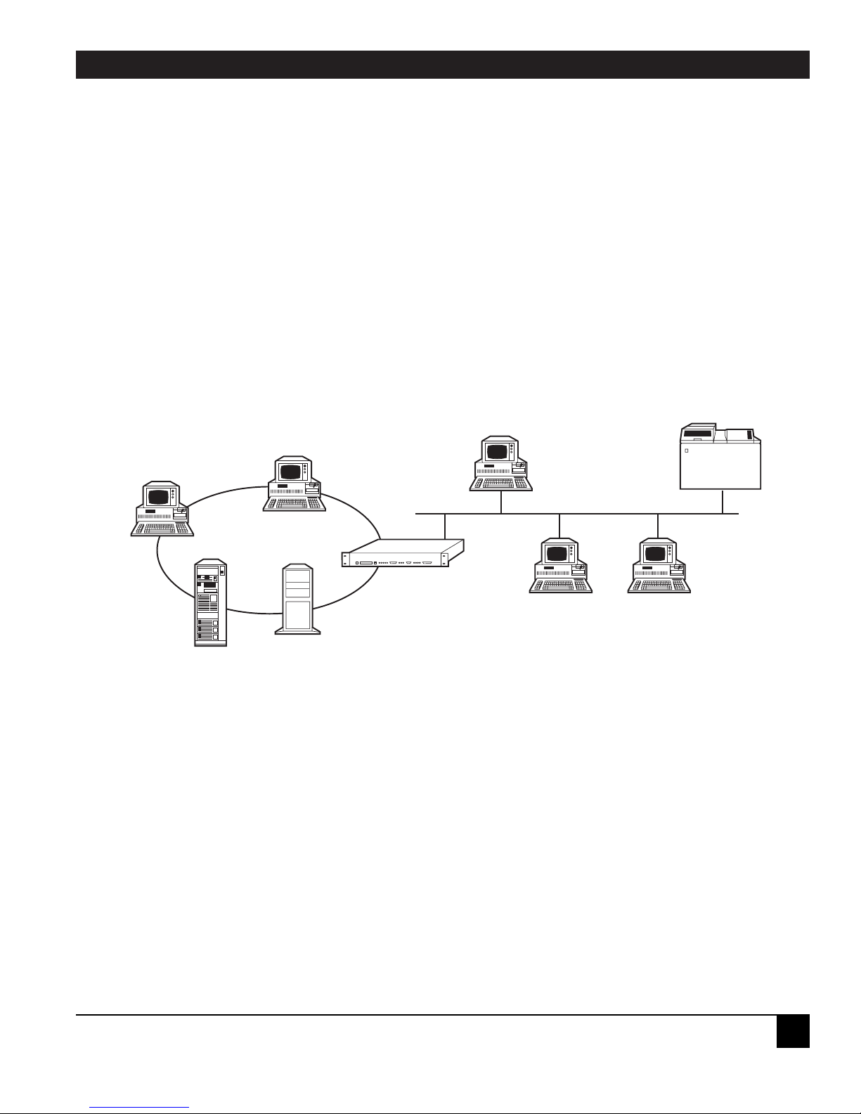
The Ethernet to Token Ring Bridge is a two-port bridge that provides connectivity between devices on a
token-ring LAN (local area network) and an Ethernet LAN. (See Figure 2-1.)
All bridges are controlled by the Bridge Manager, a software program that runs on a PC on the token-ring
LAN. The Bridge Manager performs control and statistics-gathering functions on one or more bridges and
can download operating-code upgrades to the bridges through the network.
A PC running Bridge Manager may also be attached directly to the serial control port on the Ethernet to
Token Ring Bridge. For more information, see Section 5.7.
Figure 2-1. The Ethernet to Token Ring Bridge provides
a transparent connection between the two LANs.
2. Introduction
Ethernet to Token
Ring Bridge
Ethernet
Token Ring
Bridge Manager
Program
Page 8

ETHERNET TO TOKEN RING BRIDGE
8
2.1 Features
• Conforms to the IEEE 802.1d (spanning tree), 802.2 (LLC), 802.5 (token ring) and 802.3 (Ethernet)
standards.
• Compatible with SNMP managers.
• Security and traffic control between LANs handled by flexible filtering capabilities.
• Supports TCP/IP, SNA, NetBIOS, and Novell
®
IPX™.
• Provides a transparent connection to applications running the same protocol on token-ring and Ethernet
LANs.
• Front-panel LEDs and LCD display current bridge and network status.
• Two memory banks allow reliable operating-code upgrades. Code upgrades can be downloaded through
the token-ring network without disrupting bridging operations.
• Supports the Bridge Manager Program, IBM
®
LAN Manager, and IBM LAN Network Manager.
• Supports DECnet
™
address translation.
• Emulates standard IBM server functions for communication with IBM LAN Manager, IBM LAN Network
Manager, and NetView.
• Compatible with both 4- and 16-Mbps token-ring networks.
• Two levels of password protection.
• Easily rackmounted in a standard 19" rack.
2.2 Package Contents
Before you begin installing the Bridge, inspect all items that came in the box for any signs of damage. You
should have received:
• The Ethernet to Token Ring Bridge,
• This manual,
• (1) AC power cord,
• (1) Pack of four rubber stick-on feet, and
• (1) Software download diskette.
If any of these items are missing or damaged, call Black Box.
Page 9

CHAPTER 3: Installation
9
Before installing any bridge, the network should be fully planned. For information on network planning,
you may want to read the IBM Token-Ring Network Introduction and Planning Guide (GA27-3677-01).
The NetScan feature of the Bridge Manager software simplifies the installation process because it allows you
to install an unconfigured bridge, and to configure it through the token-ring network using the Bridge
Manager. (Configuration is discussed in Chapter 4.)
3.1 What You Need for Installation
• Ethernet to Token Ring Bridge.
• Bridge Manager Program (LB7601 or LB7602).
• An Ethernet transceiver matching the Ethernet media used by your network.
• Cables (see connector pinouts in Appendix A):
Standard Type 3 or Type 1 cables between token ring port and MAU (female DB9
to RJ-45, RJ-11, or data connector, depending on MAU type).
If you are using Type 3 twisted-pair cable, you will need a media filter (LT158)
between the MAU and the bridge.
Ethernet transceiver cable (LCN200 or LCN210), if not using a micro transceiver,
for connection between the AUI (Attachment Unit Interface) and the Ethernet
transceiver.
If the Bridge Manager PC will be connected to the Ethernet to Token Ring Bridge
control port, you’ll need a straight-through DB25 cable or a DB9 to DB25 modem
cable.
3. Installation
Page 10

ETHERNET TO TOKEN RING BRIDGE
10
3.2 Setting the LAN Speed
The token-ring LAN connected to the Ethernet to Token Ring Bridge can operate at 4 or 16 Mbps. The LAN
speed can be changed either by using the Bridge Manager program or by switching a jumper on the main
circuit board inside the Ethernet to Token Ring Bridge. We recommend changing the speed via the Bridge
Manager program. The default is 4 Mbps, software-selected. Consult the Bridge Manager manual for the
procedure.
WARNING!
• If you decide to use the hardware method for changing LAN speed, the Bridge Manager
cannot be used to change the network speed. Jumper settings will override software
selections.
• Turn off the Bridge, and remove its power cord before disassembling it.
• Take appropriate anti-static measures while working on the Bridge and when handling
printed circuit boards.
To change the jumper settings:
1. Touch the Bridge’s housing to release any static electricity in your body. Unplug the Bridge’s power
cord, and remove its top cover using a phillips-head screwdriver.
2. Find the band of jumpers labeled “JP8” near the back of the unit. Locate the first two jumpers on the
left.
3. Using the figure below as a guide, place a jumper over the pins at jumper 2. This will force hardware
control of LAN speed. Set jumper 1 according to your network requirements (ON for 4 Mbps, OFF
for 16 Mbps).
4. Replace the Bridge’s top cover, screws, and power cord. Changes will take effect on power-up.
Figure 3-1. Internal jumpers that allow hardware control of token ring LAN speed.
Jumper 1:
ON for 4 Mbps
OFF for 16 Mbps
Jumper 2:
ON for hardware control
OFF for software control
Page 11

CHAPTER 3: Installation
11
3.3 Installing the Bridge
1. Make sure the LAN speed has been set correctly; see Section 3.2.
2. Install the bridge in a rack, or attach the rubber feet and set it on a table.
3. Make the Ethernet connection by attaching a transceiver, or the male end of a transceiver cable, to the
Ethernet port on the front of the bridge.
4. Connect the Token Ring port to the ring: either
(a) connect the male DB9 end of a Type 1 adapter cable to the Token Ring port on the bridge;
or
(b) attach a media filter to the Token Ring port on the bridge and then connect Type 3 cable.
5. Connect the Control Port to the PC with the Bridge Manager software (see the Bridge Manager manual for
installation instructions). Use a standard PC serial cable.
You can also use a PC with a token-ring card if you load the DXMA0MOD.SYS and DXMC0MOD.SYS
drivers.
6. Plug in the power cord and power on the bridge. It will go through some self-tests. When the tests are
finished, the LCD will show a message like “Bridge 002-9-003.” (If you don’t see that message, something
is wrong with the bridge or the connections.) This display means that Bridge 9 is connected to LAN 002
(Ethernet) and LAN 003 (Token Ring). For more information on the LCD, see Section 5.3.
The bridge will come up in Startup Mode: It will appear to be operating, but will not pass any packets.
3.3.1 I
NSTALLING THE
SNMP AGENT
1. Skip this step if you are installing a new bridge; go straight to Step 2. Connect the DC25 console port,
DCE, to the PC that has or will have the Bridge Manager software on it with a straight-type cable, or
use a Token Ring card in the PC and load the DXMAOMOD.SYS and DXMCOMOD.SYS drivers.
During the download, the following message is displayed on the Bridge’s front-panel LCD:
0123456789ABCDEF
This message will appear for one to two minutes while the downloaded code is being transferred from
volatile memory to non-volatile memory.
2. You must configure the Bridge’s IP address and netmask before the Bridge can be controlled by the
SNMP manager. To do this, start the Bridge Manager and select SNMP parameters from the
Configure menu. The screen at the top of the next page appears:
Page 12

ETHERNET TO TOKEN RING BRIDGE
12
Enter the applicable items and press <F5> to save the changes. Then perform a Bridge mode restart
(from within the Bridge Manager software) to enable bridging operations.
3.3.2 INSTALLING MIB INTO SNMP MANAGER
Incorporate the MIBs on the MIB diskette into your SNMP manager. Consult your SNMP Manager’s
documentation for the procedure.
3.4 Configuration Parameters
• Bridge IP Address — The 32-bit IP address that you intend to assign to the selected bridge. The bridge
code will first come up with the default IP address 198.17.217.1.
• Netmask — The 32-bit netmask for the bridge’s subnet. The netmask is a 32-bit mask indicating where to
divide an IP address into the network portion and the host portion. All bits in the network portion are
set to 1. All bits in the host portion are set to 0.
For example, a subnet that has a 24-bit network portion and an 8-bit host portion would have a mask of
255.255.255.0. A subnet that has a 25-bit network portion and a 7-bit host portion would have a mask of
255.255.255.128. The default netmask value is 255.255.255.0.
• Default Gateway — Indicates the IP address of the default gateway. You need this only if the bridge
communicates with SNMP managers outside its IP subnet.
• GET Community — The optional string that decides who can GET MIB variables in the bridge. The
default is PUBLIC.
• SET Community — The optional string that decides who can SET MIB variables from the bridge. The
default is PRIVATE.
• TRAP Community — The optional string that appears in the community field of all traps sent out from
this bridge. The default is PUBLIC.
• Trap Receiver IP Addresses — Up to five trap-receiver stations can be configured for each bridge. If
none are configured, the bridge does not send out a trap.
Once these parameters have been set and you have done a Bridge mode restart, the bridge can
communicate with the SNMP manager.
Bridge IP Addr [198.17 .Z17.1 ]
Net Mask [255.255.255.0 ]
Default Gateway IP Addr [00 .00 .00 .00 ]
Get Community [PUBLIC ]
Set Community [PRIVATE ]
Trap Community [PUBLIC ]
Trap Receiver 1 IP Addr [00 .00 .00 .00 ]
Trap Receiver 2 IP Addr [00 .00 .00 .00 ]
Trap Receiver 3 IP Addr [00 .00 .00 .00 ]
Trap Receiver 4 IP Addr [00 .00 .00 .00 ]
Trap Receiver 5 IP Addr [00 .00 .00 .00 ]
Esc Exit, F5 Save
SNMP PARAMETERS
Page 13

CHAPTER 4: Configuration
13
Control of a bridge using the Bridge Manager program is covered in detail in the Bridge Manager manual.
This chapter explains Bridge Manager screens and functions specific to the Ethernet to Token Ring Bridge.
When a new bridge is first turned on, it will communicate over the token ring LAN with the Bridge Manager
program. The Bridge Select function links the Bridge Manager to the Ethernet to Token Ring Bridge,
allowing you to configure the bridge through the token ring. An Ethernet to Token Ring Bridge will be
identified in the NetScan window as 4-E or 16-E, depending on the speed of the token ring.
On the Configure Bridge Parameters screen, each Ethernet to Token Ring Bridge should be configured
with a unique ring number for the token ring LAN (Ring B), a bridge number, and a virtual ring number
(Ring A) for the Ethernet. The virtual ring number is used for source-routing information in token-ring
frames.
4.1 Ethernet Parameters
In addition to token-ring parameters (covered in the Bridge Manager manual), the Bridge Manager allows for
control of the Ethernet parameters listed below. To access Ethernet parameters, go to the Configure menu
and choose Ethernet Parameters.
4.1.1 M
ODE CONVERSION
The Mode Conversion parameter is used to convert a frame received from the token ring when the
destination address is not found in the address table. If the default (Dual Mode) is selected, the frame is
converted into both Ethernet Version II format and IEEE 802.3 format, and two frames are transmitted onto
the Ethernet.
Options are Dual, IEEE 802.3, and Ethernet II.
4.1.2 B
ROADCAST CONVERSION
If the two Broadcast Conversion parameters are set to the default (Yes), the bridge will automatically convert
between the Ethernet all-stations broadcast address of FF FF FF FF FF FF and the token ring all-stations
broadcast address of C0 00 FF FF FF FF.
If Ethernet All Stations Broadcast Conversion is set to No, all-station addresses received from the Ethernet
will be sent to the token ring as FF FF FF FF FF FF.
If Token Ring All Stations Broadcast Conversion is set to No, all-station addresses received from the token
ring will be sent to the Ethernet as 03 00 FF FF FF FF (the bit-inversion of C0 00 FF FF FF FF).
4.1.3 IPX A
DDRESS BIT INVERSION
This option is for newer Novell IPX system drivers which can translate the 48-bit MAC address on each frame
from token-ring to Ethernet format, and vice versa. The default is No, meaning that addresses are not
converted.
4.1.4 S
PANNING TREE ENABLED
The default is Spanning Tree Disabled. If you enable the spanning tree, you will be able to configure it in the
SRE parameters menu. Even if this parameter is disabled, address-table maintenance, bridge forward delay,
and aging timer are still active.
4. Configuration
Page 14

ETHERNET TO TOKEN RING BRIDGE
14
4.2 MAC Addresses
The procedure for converting MAC addresses is as follows:
1. Separate the 12-digit (Ethernet or token ring) MAC address into six pairs. For example: 10 00 5A 4D BC
96.
2. Using the table below, convert the first pair. In this example, 10 translates to 08.
3. Convert the rest of the pairs in the same fashion. In this example, 10 00 5A 4D BC 96 translates to 08 00
5A B2 3D 69.
Figure 4-1. MAC addresses can be converted from both
Ethernet and token ring formats using this table.
00 80 40 C0 20 A0 60 E0 10 90 50 D0 30 B0 70 F0
08 88 48 C8 28 A8 68 E8 18 98 58 D8 38 B8 78 F8
04 84 44 C4 24 A4 64 E4 14 94 54 D4 34 B4 74 F4
0C 8C 4C CC 2C AC 6C EC 1C 9C 5C DC 3C BC 7C FC
02 82 42 C2 22 A2 62 E2 12 92 52 D2 32 B2 72 F2
0A 8A 4A CA 2A AA 6A EA 1A 9A 5A DA 3A BA 7A FA
06 86 46 C6 26 A6 66 E6 16 96 56 D6 36 B6 76 F6
0E 8E 4E CE 2E AE 6E EE 1E 9E 5E DE 3E BE 7E FE
01 81 41 C1 21 A1 61 E1 11 91 51 D1 31 B1 71 F1
09 89 49 C9 29 A9 69 E9 19 99 59 D9 39 B9 79 F9
05 85 45 C5 25 A5 65 E5 15 95 55 D5 35 B5 75 F5
0D 8D 4D CD 2D AD 6D ED 1D 9D 5D DD 3D BD 7D FD
03 83 43 C3 23 A3 63 E3 13 93 53 D3 33 B3 73 F3
0B 8B 4B CB 2B AB 6B EB 1B 9B 5B DB 3B BB 7B FB
07 87 47 C7 27 A7 67 E7 17 97 57 D7 37 B7 77 F7
0F 8F 4F CF 2F AF 6F EF 1F 9F 5F DF 3F BF 7F FF
0
1
2
3
4
5
6
7
8
9
A
B
C
D
E
F
0123456789ABCDEF
Second Character
First Character
Page 15

CHAPTER 4: Configuration
15
4.3 Ethernet Statistics
In addition to token-ring statistics (covered in the Bridge Manager manual), the Bridge Manager allows for
monitoring of the Ethernet statistics shown below. To access the LAN Status screen, select Window 3.
Figure 4-2. The Bridge Manager’s Ethernet status screen.
ETHERNET TRANSMISSION ERROR COUNTS
Lost carrier sense error count . . . . .:
Lost CTS error count . . . . . . . . . .:
Collisions error count . . . . . . . . .:
Late Collisions error count . . . . . .:
Frame Length error count . . . . . . . .:
ETHERNET RECEIVE ERROR COUNTS
Receive CRC error count . . . . . . . .:
Receive Alignment error count . . . . .:
Receive Frame error count . . . . . . .:
PAGE 1 OF 2
3.Lan Status
Page 16

ETHERNET TO TOKEN RING BRIDGE
16
5.1 Operating Modes
An Ethernet to Token Ring Bridge has two operating modes: startup and bridge mode. A bridge’s operating
mode can be changed by issuing a command from the Bridge Manager. See the Bridge Manager manual for
more information.
5.1.1 S
TARTUP M
ODE
When the bridge is powered on for the first time, it will come up in startup mode. In startup mode, a bridge
will communicate on each network, but frames will not be bridged. It will accept configuration changes,
commands, and code downloads from, and send reports to, a Bridge Manager.
NOTE
You must put the bridge in Bridge Mode to make it operational (forward packets) with the
Bridge Management software.
5.1.2 B
RIDGE M
ODE
In bridge mode, a bridge will be fully operational. It will bridge source-routed frames, communicate with the
Bridge Manager, logically filter frames (if this feature has been enabled) and emulate IBM LAN
Management Server functions. (The functions are described in the Bridge Manager manual.)
5.2 Setup Function
Setup is provided as a worst-case backup communication mechanism. Any combination of the following
conditions could make it impossible to communicate with the bridge:
• The token ring network is not functioning.
• The control port on the bridge has been configured with parameters that are unknown.
• An operating-code download has been corrupted by a power failure occurring as the code was being
recorded in the bridge’s memory.
By reconfiguring the bridge’s control port with default values, setup allows you to communicate with the
bridge under these extreme circumstances.
Invoke setup as follows:
1. Make sure that the power to the bridge is OFF.
2. On the bridge’s front panel, press and hold the Status toggle switch in the UP position.
3. While holding the Status switch in the UP position, turn the power switch ON. The bridge will
come up with the setup function activated.
Full monitoring and control of the bridge is now possible, as long as you know the bridge’s bridge link
password. See the Bridge Manager manual if you need more information on passwords.
5. Operation
Page 17

CHAPTER 5: Operation
17
5.3 LCD Displays
The LCD (liquid crystal display) on the bridge’s front panel displays various types of information.
When the bridge is first powered on, it initializes itself, and various system status messages are displayed. If
the bridge passes all self-tests and comes up successfully, a message identifying the bridge will be displayed.
An example is given below.
BRIDGE 002-9-003
This message indicates that bridge 9 is connecting rings 002 and 003. The first number (002 in this case) is
the virtual ring number assigned to the Ethernet. The last number (003) is the token-ring number.
If you press the Status switch UP repeatedly when the LCD shows the above message, several other messages
will appear. These are described below:
E-NET TEST OK
Indicates that the status of Ring A, the Ethernet, is OK.
E-NET FAILED
Indicates that the Ethernet diagnostic routine failed during power-up. If this message appears, check the
cable attaching the bridge to the Ethernet MAU.
T-RING status nnn
In the place of status will be either OPEN, CLOSED, or INIT. INIT indicates that the token ring is
initializing. After OPEN or CLOSED, in the place of nnn will be one of the entries in the chart below.
Display Meaning
h04 4 Mbps, hardware-selected
h16 16 Mbps, hardware-selected
s04 4 Mbps, software-selected
s16 16 Mbps, software-selected
MODE type
In the place of type will be either STARTUP or BRIDGE for the current operating mode of the bridge.
Operating modes are covered earlier in this chapter.
FRAMES nnnn /SEC
nnnn will be replaced by the number of frames bridged per second. The number will dynamically change as
the number of frames rises and falls. This display operates only when the bridge unit is in bridge mode and
both ports of the bridge have successfully inserted on their respective rings.
MAC nnnnnnnnnnnn
The 12-digit IEEE MAC-level address of Ring B, in token-ring format. The MAC addresses for the two rings
are consecutive. (The address for the Ethernet is this number plus one.) This MAC address can be
overridden using the Bridge Manager, but the original IEEE address will always be displayed on the LCD.
Page 18

ETHERNET TO TOKEN RING BRIDGE
18
VERSION LLC nnnn
This message displays the current LLC code version level.
VERSION HDW nnnn
This message is the hardware revision level when the bridge was manufactured. If a bridge has received a
factory hardware upgrade, however, the version number displayed here will not be accurate. When in doubt,
check the label on the bottom of the bridge housing.
VERSION FMW nnnn
This message displays the current firmware version level.
VERSION DWN nnnn
This message displays the current downloaded operating code version level. If no operating code has been
downloaded into the active bank, the value will be xxxx.
SYSTEM CODE nnnn
This message can be useful during problem diagnosis. Following the words SYSTEM CODE will be a fourdigit number. This is a hexadecimal word. If it is translated into binary, each bit indicates a particular
condition. See the chart on the next page for an explanation of each bit.
To return to the first message, repeatedly press the Status switch DOWN.
Page 19

CHAPTER 5: Operation
19
X X X X X X X X X X X X X X X X
1 = Download-code
mismatch
1 = Forced EEPROM
initialization
1 = Reset from Bridge
Manager
1 = RAM error detected
1 = LCD error
1 = Async-control-port
error detected
1 = Error in Flash
EEPROM CRC
1 = Failure during task
creation
1 = Address-line error
detected
1 = Data-bus error
detected
1 = Setup was
requested
1 = Watchdog timeout
occurred
1 = System-clock error
detected
1 = EEPROM was
initialized
1 = EEPROM error
detected
1 = Insufficient working
RAM
Page 20

ETHERNET TO TOKEN RING BRIDGE
20
Figure 5-1. The Bridge’s front panel.
5.4 LED Functions
•PWR — On (green) when the Bridge is connected to a power source and turned on.
•OK — Blinking (green) when the bridge system is OK. If it is on solid or off, there’s a problem.
•COL — On (red) when a collision has been detected on the Ethernet bus.
•TxD — On (green) when frames are being transmitted by the Bridge onto the Ethernet.
•RxD — On (green) when frames are being received by the Bridge from the Ethernet.
•H — On (red) indicates a token-ring hard error. If it is on solid, the ring station is closed. If it is
blinking, the station has been removed from the ring.
•S — On (yellow) indicates a token ring soft error. If it is on solid, the station is in the process of opening
onto the ring. Continuous blinking indicates the ring is beaconing. Occasional soft errors are normal.
•N — On (green) indicates normal token ring communication.
The four green LEDs labeled DSR, DTR, TxD, and RxD are associated with the RS-232 serial control port.
They are lit when there is activity on those pins.
POWER
STATUS
PWR OK
CONTROL PORT
COL TxD RxD DSR DTR TxD RxD
Ethernet to Token Ring Bridge
TOKEN RINGETHERNET
Power
Switch
LCD
Status
Switch
Ethernet
AUI Port
Token Ring
Port
Control
Panel
Control Port
LEDs
HSN
Token Ring
LEDs
Ethernet
LEDs
System
LEDs
Page 21

CHAPTER 5: Operation
21
5.5 Detailed Hardware Diagnostics
Use the Bridge’s LCD panel when troubleshooting.
To run detailed hardware diagnostics, turn the Bridge OFF. Press and hold the Status toggle switch in the
DOWN position and turn the Bridge back ON.
The bridge will go through a series of detailed self-tests. Various messages will be displayed for several
moments. Some messages will repeat. The last message displayed will be Init LAN1. When this happens, the
LEDs on the Bridge’s front panel will flash on and off.
5.6 Downloading Operating Code
Because the Ethernet to Token Ring Bridge hardware is equipped with two flash memory banks, it is possible
to download and store two separate versions of the bridge operating code through the network. The Bridge
Manager will automatically download code to the memory bank not currently in use. To download new
operating code, follow the procedure for downloading code in the Bridge Manager manual.
Once code has been downloaded, the Bridge Manager will prompt you to restart the Bridge. The Bridge will
automatically switch memory banks, enabling the new code. If you need to manually switch the Ethernet to
Token Ring Bridge’s memory banks, use the Toggle download function or press <Ctrl/F10> to bring up the
memory-bank selection window. Press <F5> to save changes. This will take effect if you select a restart option
from the Bridges menu.
5.7 The Serial Control Port
A bridge’s serial control port allows you to bypass the network and connect the Bridge Manager PC directly
to the bridge. All control and monitoring functions that can be performed through the network may also be
performed with a direct connection to the control port. When you attach the Bridge Manager to a control
port, it will override any other Bridge Manager on the LAN.
When the Bridge Manager PC is connected to a bridge’s control port, it can communicate with that bridge
only. If you have more than one bridge (local or remote) on your network, you will probably only use the
control port when there is some network problem.
Control-port default parameters are as follows:
Parameter Default Range
Bit Rate 9600 300, 600, 1200, 2400, 4800, 9600
Parity None None
Data Bits 8 8
Stop Bits 1 1 or 2
Flow Control None XON, None, RTS
Device Ready None DTR or None
Page 22

ETHERNET TO TOKEN RING BRIDGE
22
To connect a PC to a Ethernet to Token Ring Bridge control port:
1. Connect a straight-through RS-232 cable between the PC’s COM1 port and the bridge’s control port. If
you are using modems, set the bridge-side modem to auto-answer (and you will need RS-232 crossover
cables). Connector pinouts are given in Appendix A.
2. Power on the Bridge Manager PC, if necessary.
3. If the Bridge’s control port is configured with default parameters (shown on the previous page), enter
TRBRIDGE at the PC’s DOS prompt. This will start the Bridge Manager and configure the PC’s COM1
port with default parameters.
4. If you need to change your PC’s parameters, you can add them to the TRBRIDGE command line. The
syntax is:
TRBRIDGE comport bps parity databits stopbits
comport must be either COM1 or COM2.
bps is the data rate. The allowable entries are 300, 600, 1200, 2400, 4800, and 9600. These may be
abbreviated to two digits, such as 24 for 2400.
parity must be N for none, O for odd, or E for even.
databits must be 8.
stopbits must be either 1 or 2.
5. If you need to change the bridge’s control-port parameters, consult the Bridge Manager manual. If you
don’t know what the control-port parameters are, you’ll have to use the setup function to force the
defaults.
Page 23

APPENDIX A: Cable Diagrams
23
IMPORTANT!
The Token Ring Interface on the Ethernet to Token Ring Bridge does not include a media
filter. If UTP cabling is used, you must use an external media filter to comply with FCC
radiation regulations.
The DB25 Control Port is a standard DB25 serial port and is always DCE. It supports hardware flow control
(RTS/CTS) and software flow control (XON or None). If a bridge is configured to use DTR for Device
Ready, then the PC must assert DTR.
A standard RS-232 pinout diagram is shown below for both DCE and DTE. Be sure to select the right pinouts
for your equipment interface.
Figure A-1. Control Port Interface: DB25 to DTE and DCE.
PC’s DB25
COM1 Port
Pins (DTE)
1
TX 2
RX 3
DTR 20
DSR 6
RTS 4
CTS 5
7
Signal
Ground
Frame
Ground
Bridge’s
Control Port
Pins (DCE)
1
RX 2
TX 3
DSR 20
DTR 6
CTS 4
RTS 5
7
Signal
Ground
Frame
Ground
Modem’s
DB25 Port
Pins (DCE)
1
RX 2
TX 3
DSR 20
DTR 6
CTS 4
RTS 5
7
Signal
Ground
Frame
Ground
(optional)
(optional)
Appendix A: Cable Diagrams
Page 24

ETHERNET TO TOKEN RING BRIDGE
24
The DB15 Attachment Unit Interface is a standard for connection to an Ethernet transceiver. Connector
pinouts are shown below.
Figure A-2. Ethernet Attachment Unit lnterface.
DB15 AUI Pins
Shield 1 1
Collision Presence + 2 2
Transmit + 3 3
Reserved 4 4
Receive + 5 5
Power Return 6 6
Reserved 7 7
Reserved 8 8
Collision Presence – 9 9
Transmit – 10 10
Reserved 11 11
Receive – 12 12
Power 13 13
Reserved 14 14
Reserved 15 15
Shield must be terminated to
connector shell as well as to Pin 1.
Page 25

APPENDIX B: Ethernet to Token Ring Bridge MIB
25
The Ethernet to Token Ring Bridge SNMP agent supports the following Management Information Bases
(MIBs):
• RFC1286
• RFC1213
B.1 The brSnmpConfigParam Group
This group contains variables needed to configure the SNMP agent. New values set to variables in this group
will take effect only after a bridge restart (see the Bridge Manager manual).
• brIpAddress — The bridge’s own IP address.
• brNetmask — The bridge’s netmask.
• brDefaultGateway — The default gateway to which this IP layer sends those IP datagrams that are
heading for stations outside this subnet.
• brTrapCommunity — The community string to be used in traps sent by this agent.
• brTrapReceiverIpAddr1, 2, 3, 4, 5 — The IP address of a management station that will receive traps
from this agent.
B.2 The brBridgeAdditionalParam Group
Included in this group are some useful existing bridge parameters that have not been defined by RFC1286.
New values set to variables in this group will take effect only after a bridge restart.
brEEPromSRBcastAutoMode — Yes (1) specifies that the bridge is to participate in the automatic, single-
route, broadcast-enable process for source-routing-only bridges. The bridge’s single-route broadcast
parameters for port A and port B (variables brSingleRouteBroadcastAToB and
brSingleRouteBroadcastBToA) will be automatically configured for the appropriate setting.
No (0) specifies Manual Mode. The bridge’s single-route broadcast parameters (variables
brSingleRouteBroadcastAToB and brSingleRouteBroadcastBToA) must be manually set. The default is No
for Manual Mode.
brEEPromSRBcastAToB (or BToA) — This variable is meaningful only when brEEPromSRBcastAutoMode is
set to No (0). In other words, it is in Manual Mode.
Yes (1) allows single-route broadcast frames to pass from the named port to its opposite port if the hop
count limit has not been reached for that frame.
No (0) causes all single-route broadcast frames received by the first-named port to be discarded.
Appendix B: Ethernet to
Token Ring Bridge MIB
Page 26

ETHERNET TO TOKEN RING BRIDGE
26
B.3 The brOperationalParam Group
Most of the variables in this group have a counterpart variable in either the RFC1286’s dot1dSr or the
brBridgeAdditionalParam group. The values of the variables in this group may be different from those of
their counterparts in the other two groups because variables in the other two groups can be set to different
values any moment. However, these new stored values have no effect on the current operation of the bridge.
They will only take effect on the next RESET.
brBridgeModeRestart — Setting this parameter to Yes (1) causes the bridge to do a BRIDGE MODE
RESTART.
brOperationalHopCount — Corresponding counterpart in dot1dsr group: dot1dSrPortHopCount.
brOperationalBridgeNumber — Corresponding counterpart in dot1dsr group: dot1dSrPortBridgeNum.
brOperationalRingNumberA (or NumberB) — Corresponding counterpart in dot1dsr group:
dot1dSrPortLocalSegment of Port A and dot1dSrPortTargetSegment of Port A.
brOperationalSRBcastAutoMode — Corresponding counterpart in brBridgeAdditionalParam group:
brEEPromSRBcastAutoMode.
brOperationalSRBcastAToB (or BToA) — Corresponding counterpart in brBridgeAdditionalParam group:
brEEPromSRBcastAToB.
B.4 The brPerformanceParam Group
brSamplinglntervalLen — The time interval, measured in seconds, during which the performance variables
are calculated. The default is 10 seconds.
brBcastFramesPerSecondAToB (or BToA) — The average number of frames-per-second being bridged from
port A to port B in the previous measuring period. The length of the measuring period is determined by
variable brSamplingIntervalLen.
brNonBcastFramesPerSecondAToB (or BToA) — The average number of frames-per-second being bridged
from port A to port B in the previous measuring period. The length of the measuring period is determined
by variable brSamplingIntervalLen.
brBcastBytesPerSecondAToB (or BToA) — The average number of bytes-per-second being bridged from
port A to port B in the previous measuring period. The length of the measuring period is determined by
variable brSamplingIntervalLen.
brNonBcastBytesPerSecondAToB (or BToA) — The average number of bytes-per-second being bridged
from port A to port B in the previous measuring period. The length of the measuring period is determined
by variable brSamplingIntervalLen.
B.5 Traps for Bridge Operations
PerformanceThreshholdExceeded — The percentage of lost frames has exceeded the threshold value. This
trap is sent every time a 8507 (Bridge Performance Threshold Exceeded) Frame is sent to LAN Manager.
 Loading...