

Page 1

1000 Park Drive • Lawrence, PA 15055-1018 • 724-746-5500 • Fax 724-746-0746
© Copyright 1998. Black Box Corporation. All rights reserved.
Page 2
Order toll-free in the U.S.: Call 877-877-BBOX (outside U.S. call 724-746-5500)
FREE technical support 24 hours a day, 7 days a week: Call 724-746-5500 or fax 724-746-0746
Mailing address: Black Box Corporation, 1000 Park Drive, Lawrence, PA 15055-1018
Web site: www.blackbox.com • E-mail: info@blackbox.com
CUSTOMER
SUPPORT
INFORMATION
AUGUST 1998
LB3104A-AUI-R3 LB3135A-AUI-R3 LB3804A-AUI-R3 LB3835A-AUI-R3
LB3104A-BNC-R3 LB3135A-BNC-R3 LB3804A-BNC-R3 LB3835A-BNC-R3
LB3104A-BT-R3 LB3135A-BT-R3 LB3804A-BT-R3 LB3835A-BT-R3
LB3124A-AUI-R3 LB3136A-AUI-R3 LB3824A-AUI-R3 LB3836A-AUI-R3
LB3124A-BNC-R3 LB3136A-BNC-R3 LB3824A-BNC-R3 LB3836A-BNC-R3
LB3124A-BT-R3 LB3136A-BT-R3 LB3824A-BT-R3 LB3836A-BT-R3
Ethernet Extenders
Configuration Guide
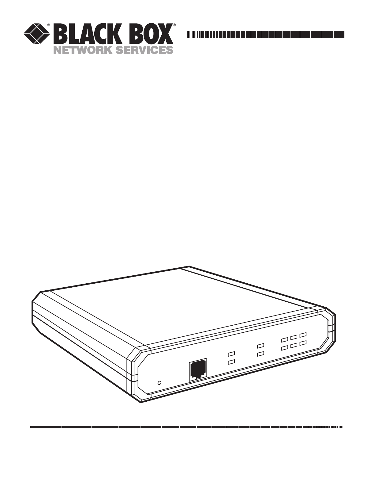
ETHERNET EXTENDER
CONTROL
RESET
READY
POWER
REMOTE
MAIN
LINK
LAN
ERR
Rx
Tx
Page 3

Page 4

FCC INFORMATION
1
FEDERAL COMMUNICATIONS COMMISSION
AND
INDUSTRY CANADA
RADIO FREQUENCY INTERFERENCE STATEMENTS
This equipment generates, uses, and can radiate radio-frequency energy, and if not installed and used
properly, that is, in strict accordance with the manufacturer’s instructions, may cause interference to radio
communication. It has been tested and found to comply with the limits for a Class A computing device in
accordance with the specifications in Subpart B of Part 15 of FCC rules, which are designed to provide
reasonable protection against such interference when the equipment is operated in a commercial
environment. Operation of this equipment in a residential area is likely to cause interference, in which
case the user at his own expense will be required to take whatever measures may be necessary to correct
the interference.
Changes or modifications not expressly approved by the party responsible for compliance could void the user’s
authority to operate the equipment.
This digital apparatus does not exceed the Class A limits for radio noise emission from digital apparatus set out in the Radio
Interference Regulation of Industry Canada.
Le présent appareil numérique n’émet pas de bruits radioélectriques dépassant les limites applicables aux appareils numériques
de la classe A prescrites dans le Règlement sur le brouillage radioélectrique publié par Industrie Canada.
Page 5

ETHERNET EXTENDERS—CONFIGURATION GUIDE
2
INSTRUCCIONES DE SEGURIDAD (Normas Oficiales Mexicanas Electrical Safety Statement)
1. Todas las instrucciones de seguridad y operación deberán ser leídas antes de que el aparato eléctrico sea operado.
2. Las instrucciones de seguridad y operación deberán ser guardadas para referencia futura.
3. Todas las advertencias en el aparato eléctrico y en sus instrucciones de operación deben ser respetadas.
4. Todas las instrucciones de operación y uso deben ser seguidas.
5. El aparato eléctrico no deberá ser usado cerca del agua—por ejemplo, cerca de la tina de baño, lavabo, sótano
mojado o cerca de una alberca, etc..
6. El aparato eléctrico debe ser usado únicamente con carritos o pedestales que sean recomendados por el fabricante.
7. El aparato eléctrico debe ser montado a la pared o al techo sólo como sea recomendado por el fabricante.
8. Servicio—El usuario no debe intentar dar servicio al equipo eléctrico más allá a lo descrito en las instrucciones de
operación. Todo otro servicio deberá ser referido a personal de servicio calificado.
9. El aparato eléctrico debe ser situado de tal manera que su posición no interfiera su uso. La colocación del aparato
eléctrico sobre una cama, sofá, alfombra o superficie similar puede bloquea la ventilación, no se debe colocar en
libreros o gabinetes que impidan el flujo de aire por los orificios de ventilación.
10. El equipo eléctrico deber ser situado fuera del alcance de fuentes de calor como radiadores, registros de calor, estufas
u otros aparatos (incluyendo amplificadores) que producen calor.
11. El aparato eléctrico deberá ser connectado a una fuente de poder sólo del tipo descrito en el instructivo de
operación, o como se indique en el aparato.
12. Precaución debe ser tomada de tal manera que la tierra fisica y la polarización del equipo no sea eliminada.
13. Los cables de la fuente de poder deben ser guiados de tal manera que no sean pisados ni pellizcados por objetos
colocados sobre o contra ellos, poniendo particular atención a los contactos y receptáculos donde salen del aparato.
14. El equipo eléctrico debe ser limpiado únicamente de acuerdo a las recomendaciones del fabricante.
15. En caso de existir, una antena externa deberá ser localizada lejos de las lineas de energia.
16. El cable de corriente deberá ser desconectado del cuando el equipo no sea usado por un largo periodo de tiempo.
17. Cuidado debe ser tomado de tal manera que objectos liquidos no sean derramados sobre la cubierta u orificios de
ventilación.
18. Servicio por personal calificado deberá ser provisto cuando:
A: El cable de poder o el contacto ha sido dañado; u
B: Objectos han caído o líquido ha sido derramado dentro del aparato; o
C: El aparato ha sido expuesto a la lluvia; o
D: El aparato parece no operar normalmente o muestra un cambio en su desempeño; o
E: El aparato ha sido tirado o su cubierta ha sido dañada.
Page 6

TRADEMARKS USED AND TELECOMMUNICATION SAFETY
3
TRADEMARKS USED IN THIS MANUAL
Any trademarks mentioned in this manual are acknowledged to be the property of the trademark owners.
Telecommunication Safety
The safety status of each of the ports on the Ethernet Extender is declared according to EN 41003 and is
detailed in the table below:
Safety Status Ports
SELV V.24, V.35, V.36, LAN
TNV-1 4W
SELV = Safety Extra-Low Voltage
TNV-1 = Telecommunications Network Voltage within the limits of SELV and subject to overvoltages
Page 7

ETHERNET EXTENDERS—CONFIGURATION GUIDE
4
Contents
Chapter Page
1. Introduction ............................................................................................................................................................6
1.1 A General Description ............................................................................................................................6
1.2 How “Single IP” Address Translation Works ..........................................................................................7
1.2.1 What Single IP Does ..........................................................................................................................7
1.2.2 The Benefits of Single IP....................................................................................................................8
1.3 Solid Firewall ............................................................................................................................................9
1.4 Ethernet Extender Features ....................................................................................................................9
1.5 Ethernet Extender Applications ..........................................................................................................11
1.5.1 Bridging ............................................................................................................................................11
1.5.2 4-Wire Modem ..................................................................................................................................11
1.5.3 Single IP ............................................................................................................................................12
2. Configuration Introduction ..................................................................................................................................13
2.1 How to Start Configuring the Ethernet Extender ..............................................................................13
2.1.1 Connecting to the Internet/Intranet as a Public IP Net ..............................................................13
2.1.2 Connecting to the Internet/Intranet as a Private IP Net (Using Single IP)................................14
2.2 Initial Setup ............................................................................................................................................15
2.2.1 Connecting to the Terminal ............................................................................................................15
2.2.2 Setting a Password ............................................................................................................................16
2.2.3 Changing and Deleting the Password ............................................................................................16
2.3 The Quick Setup Menu ........................................................................................................................17
2.4 Menus and Screens ................................................................................................................................17
2.4.1 The Main Menu ................................................................................................................................17
2.4.2 Quick Setup ......................................................................................................................................17
2.4.3 Security Setup ..................................................................................................................................17
2.4.4 Advanced Menu ................................................................................................................................18
2.4.5 View....................................................................................................................................................18
2.4.6 Diagnostic Tools................................................................................................................................18
2.4.7 Exit ....................................................................................................................................................18
3. Quick Setup Menu ................................................................................................................................................19
3.1 Quick Setup Menu Parameters ............................................................................................................19
3.1.1 Link Mode ........................................................................................................................................21
3.1.2 Routing ..............................................................................................................................................21
3.1.3 Connection........................................................................................................................................21
3.1.4 WAN IP Address................................................................................................................................21
3.1.5 BOOTP Address................................................................................................................................21
3.1.6 Modem Type ....................................................................................................................................21
3.1.7 Baud Rate ..........................................................................................................................................21
3.1.8 Host IP Setup ....................................................................................................................................22
3.1.9 Security Setup ..................................................................................................................................23
3.2 Where To Go From Here ......................................................................................................................24
Page 8

CONTENTS
5
Chapter Page
4. Security Setup Menu..............................................................................................................................................25
4.1 Enabling TELNET Access......................................................................................................................26
4.2 Enabling SNMP Access ..........................................................................................................................27
4.3 Enabling/Disabling the Solid Firewall ................................................................................................28
5. Advanced Setup Menu ..........................................................................................................................................30
5.1 Advanced Menu and Setup Menu ........................................................................................................30
5.2 Device Control Menu ............................................................................................................................79
5.3 List of Operations ..................................................................................................................................85
Appendix A: Important ISDN Issues (For U.S. Users Only)....................................................................................89
A.1 Which ISDN Service Should You Order? ............................................................................................89
A.2 Ordering ISDN ......................................................................................................................................89
A.3 Provisioning ISDN..................................................................................................................................89
A.4 ISDN Parameters ....................................................................................................................................89
Appendix B: BOOT Manager ....................................................................................................................................92
B.1 Preface ....................................................................................................................................................92
B.2 Accessing BOOT Manager ....................................................................................................................92
B.2.1 Access via Software Download Menu ..............................................................................................92
B.2.2 Rescue................................................................................................................................................93
B.3 The BOOT Manager Menu ..................................................................................................................93
B.3.1 Load New Software ..........................................................................................................................94
B.3.2 Partitions Status ................................................................................................................................94
B.3.3 Run Second Partition ......................................................................................................................94
B.3.4 Reactivate Second Partition ............................................................................................................95
B.3.5 Duplicate First Partition ..................................................................................................................95
B.3.6 Erase Configuration..........................................................................................................................95
B.3.7 Erase All FLASH ..............................................................................................................................95
B.3.8 Set Baud Rate ....................................................................................................................................95
B.3.9 Exit ....................................................................................................................................................96
Page 9

ETHERNET EXTENDERS—CONFIGURATION GUIDE
6
1. Introduction
Ethernet Extenders can be used for various bridging and routing functions, and can connect an Ethernet or
Token Ring LAN to the Internet or Intranet via ISDN, Frame Relay, asynchronous or synchronous dialup, or
Digital Data Service (DDS) links operating at data rates up to 1.5 Mbps.
This manual gives a general introduction to the Ethernet Extender and describes how to configure it. For
information about the physical features or installing Ethernet Extenders, refer to the Ethernet Extender
Installation and Operation Guide.
1.1 A General Description
Ethernet Extenders are standalone bridges and IP/IPX routers for the small office. Quick setup and advanced
configuration menus provide on-screen instructions that guide you through the configuration procedures.
The Ethernet Extender features:
• Bridging.
• IP Routing.
• IPX Routing.
• Address Translation.
• Firewall.
Bridging
The Ethernet Extender supports standard bridging functions. Because bridging is the Ethernet Extender’s
default, you can use the Ethernet Extender as a bridge with little or no configuration.
IP Routing
The Ethernet Extender is an IP router that supports:
• Static IP net configuration.
• Dynamic IP net learning using the RIP and RIP-2 protocols.
• CIDR topologies.
• Multiple IP nets on the LAN or WAN interfaces.
• Numbered and unnumbered I/F.
• IP fragmentation.
IPX Routing
In addition to IP routing, the Ethernet Extender also supports standard IPX routing and includes support for
RIP and SAP.
Page 10
CHAPTER 1: Introduction
7
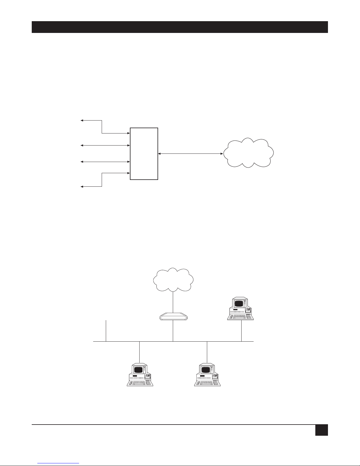
1.2 How “Single IP” Address Translation Works
Single IP allows users in a small-office LAN to connect to the Internet/Intranet quickly and transparently with
just one assigned IP address.
1.2.1 W
HAT SINGLE IP DOES
Single IP is an Ethernet Extender feature that translates multiple IP addresses on a small-office LAN to one
single IP address on the Internet.
Figure 1-1. IP connection to the Ethernet Extender.
Normally, a LAN requires a complete statically assigned, unique and legal subnet, with one IP address for every
station, in order to connect to the Internet or Intranet. Single IP allows an entire small office to connect to the
Internet or corporate intranet using only one dynamically or statically assigned IP address received from the
ISP via a dial-up modem, ISDN connection, leased line, DDS, or Frame Relay line.
Figure 1-2. Ethernet Extender with Single IP enabled.
Small Office
Ethernet
Ethernet Extender
Internet (ISP)
or Intranet
IP
1
IP
2
IP
3
IP
4
Ethernet
Extender
Single IP
IP
Internet/Intranet
Page 11
ETHERNET EXTENDERS—CONFIGURATION GUIDE
8
Configure the Ethernet Extender to dial an Internet/Intranet Access Router and to supply a user name and
password over PPP. The Internet/Intranet Access Router automatically supplies the Ethernet Extender with a
single temporary IP address using the IPCP protocol—the same way that a single PC would connect directly to
the ISP.
You can connect a complete small-office LAN with a private subnet to the Ethernet Extender. Through the
Ethernet Extender you can access the Internet/Intranet. The Internet/Intranet provider does not need to
specially coordinate with the office or allocate subnets.
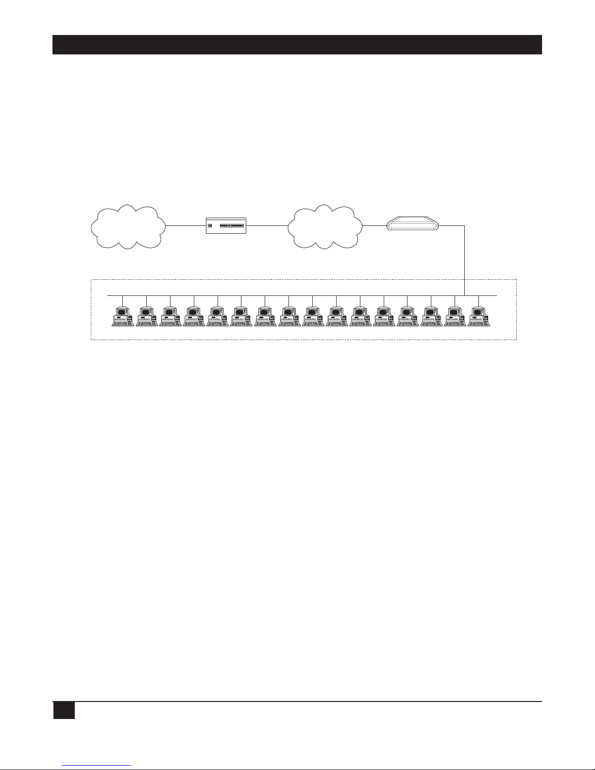
Figure 1-3. Ethernet Extender in Single IP Mode.
1.2.2 T
HE BENEFITS OF SINGLE IP
• Allows a small office to connect to the Internet/Intranet in the same way as a single PC.
• Requires only one legal IP address.
• Obtains a single legal IP address from the Internet/Intranet Access Router using standard IPCP.
• Allows a small office to access any public IP subnet.
• Allows Web browsing, FTP, Telnet, e-mail, news and other IP applications using any TCP/IP stack on any
type of station in the small office.
• Provides security against Internet hackers using the Solid Firewall feature.
• Allows automatic connection and disconnection of the link based on actual or specific use of the
Internet/Intranet.
• Allows filtering of traffic on the link to reduce waste of bandwidth and to improve security.
Private Subnet 192.168.1.
RFC 1918
16 potential users
3 concurrent users (.4, .11, .14)
Ethernet Extender
(Single IP feature enabled)
192.168.1.1.
Ethernet Extender
ISDN
FR
PSTN
Leased Line
Central Access
Router
Internet/Intranet
Page 12

CHAPTER 1: Introduction
9
IP Applications: Web Browsing, FTP, Telnet, E-mail, News and Others
Single IP allows the use of any Web browser, such as Netscape or Internet Explorer, to access the World-Wide
Web. Refer to the list below for some of the types of Internet and Intranet access supported by Single IP:
• World Wide Web browsing.
• E-mail.
• FTP client.
• News reader.
• Telnet client.
• Ping (outbound).
Single IP supports any SOCKS-compatible client application (for example, Netscape). Access to FTP within
Netscape, Gopher access, and access to secure servers is also supported. POP3 clients (for example, Eudora,
Pegasus mail, Microsoft Exchange) and other e-mail packages and news readers are allowed access to e-mail
servers through Single IP e-mail support.
Single IP allows use of FTP client applications that support the username@hostname method of firewall
crossing; for example, WS_FTP, CuteFTP, and command-line FTP clients. Connection through another firewall
using the same mechanism is also allowed.
1.3 Solid Firewall
The Solid Firewall feature prevents access from the Internet/Intranet into the small-office LAN. This feature
makes the small-office LAN invisible to outside users. The Solid Firewall feature is a simple and foolproof way of
protecting security sensitive small offices (for example, doctors and lawyers) from Internet hackers. Refer to
Chapter 4 for more information about the Firewall.
1.4 Ethernet Extender Features
• Supports bridging.
• Supports IP, IPX, and IP+IPX routing.
• Supports Single IP feature (IP Address Translation) which allows a user to connect to the Internet/Intranet.
• Supports static nets and multi-nets. Refer to Chapter 5.
• Supports IP fragmentation. Refer to Chapter 5.
• PPP multi-link support enables maximum utilization of ISDN lines. Refer to Chapter 5.
• Supports bandwidth on demand (BOD). Refer to Chapter 5.
• Integral Frame Relay operating at data rates up to T1. Refer to Chapter 5.
• Supports 4-wire, asynchronous, synchronous, ISDN and CSU/DSU WAN interfaces.
• Supports Token Ring, 10BASE2, 10BASE5, or 10BASE-T LAN interface.
Page 13

ETHERNET EXTENDERS—CONFIGURATION GUIDE
10
• Supports backup links for bridge and router links.
• Supports TELNET, allowing configuration and control of the device over WAN and LAN. Refer to
Chapter 3.
• Supports RADIUS. Refer to Chapter 5.
• Fast configuration can be performed from a terminal emulator, and via TELNET. Refer to Chapter 3.
• An SNMP agent provides management by any standard SNMP management station. Refer to Chapter 5.
• Software downloading is available using XMODEM or TFTP. Refer to Chapter 5.
• Dual-image flash enables downloading two software versions. Refer to Chapter 5.
• Independent ISDN code downloading is available using XMODEM. Refer to Chapter 5.
• Indicates ISDN link integrity. Refer to Chapter 5.
• Connection on Demand feature reduces WAN costs. Refer to Chapter 5.
• PAP/CHAP provides access authentication. Refer to Chapter 5.
• Solid Firewall feature allows the user to block all access from the outside into the LAN. Refer to Chapter 4.
• Undesired access to Ethernet Extender via TELNET or SNMP can also be blocked or password-protected.
Refer to Chapter 4.
Page 14

CHAPTER 1: Introduction
11
1.5 Ethernet Extender Applications
The Ethernet Extender can be used in a large variety of applications. Some examples follow.
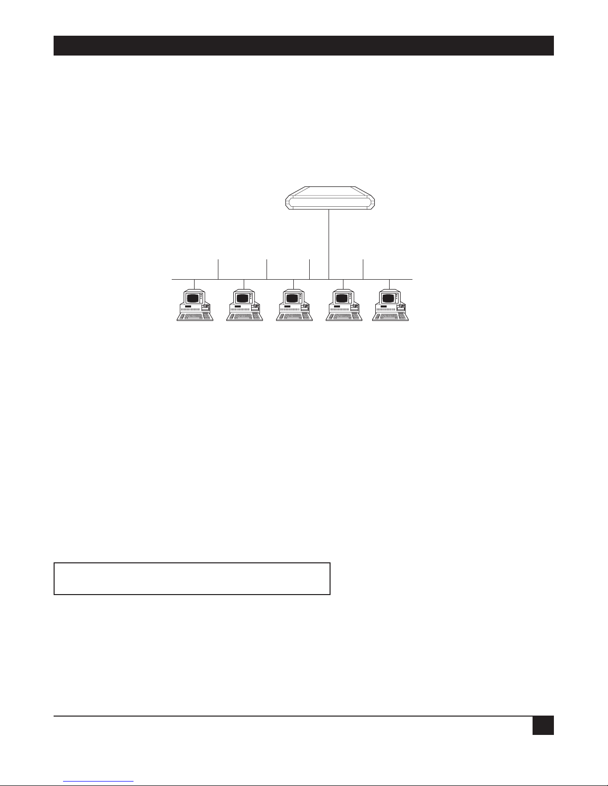
1.5.1 B
RIDGING
Two Ethernet Extenders can be used opposite each other in a standard bridging application. The Ethernet
Extender connected to the larger network or to a network with connections to other networks, is the Main
Ethernet Extender. The Ethernet Extender connected to the smaller network is the Remote Ethernet Extender.
Refer to Figure 1-4.
Figure 1-4. Standard Bridging Application.
1.5.2 4-W
IRE MODEM
The Ethernet Extender has a built-in 4-wire modem and can be used for one or more PCs to connect to each
other or to the Internet. Refer to Figure 1-5.
Figure 1-5. Connecting to the Ethernet Extender via a 4-Wire Modem.
4-Wire Modem
4-Wire Modem
Ethernet Extender
PC
Internet
Internet
Router
Ethernet Extender
Ethernet Extender
Remote
Main
Page 15
ETHERNET EXTENDERS—CONFIGURATION GUIDE
12
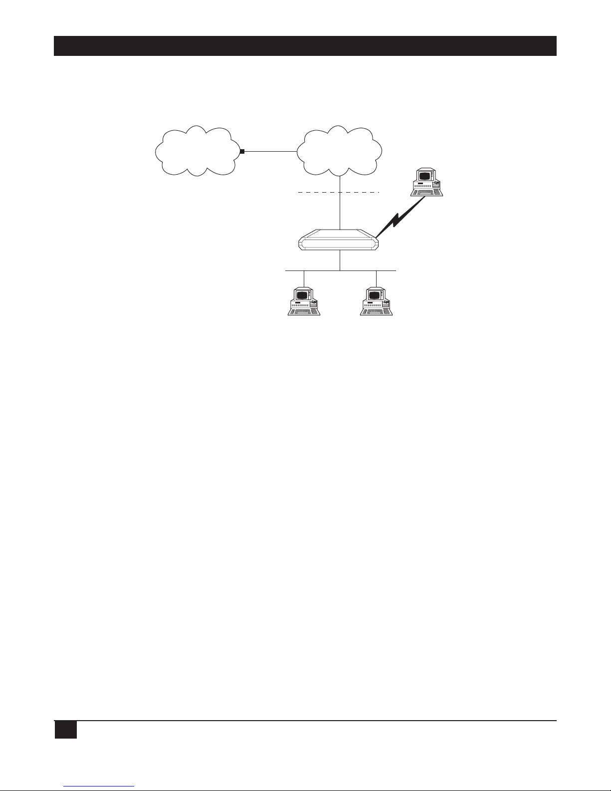
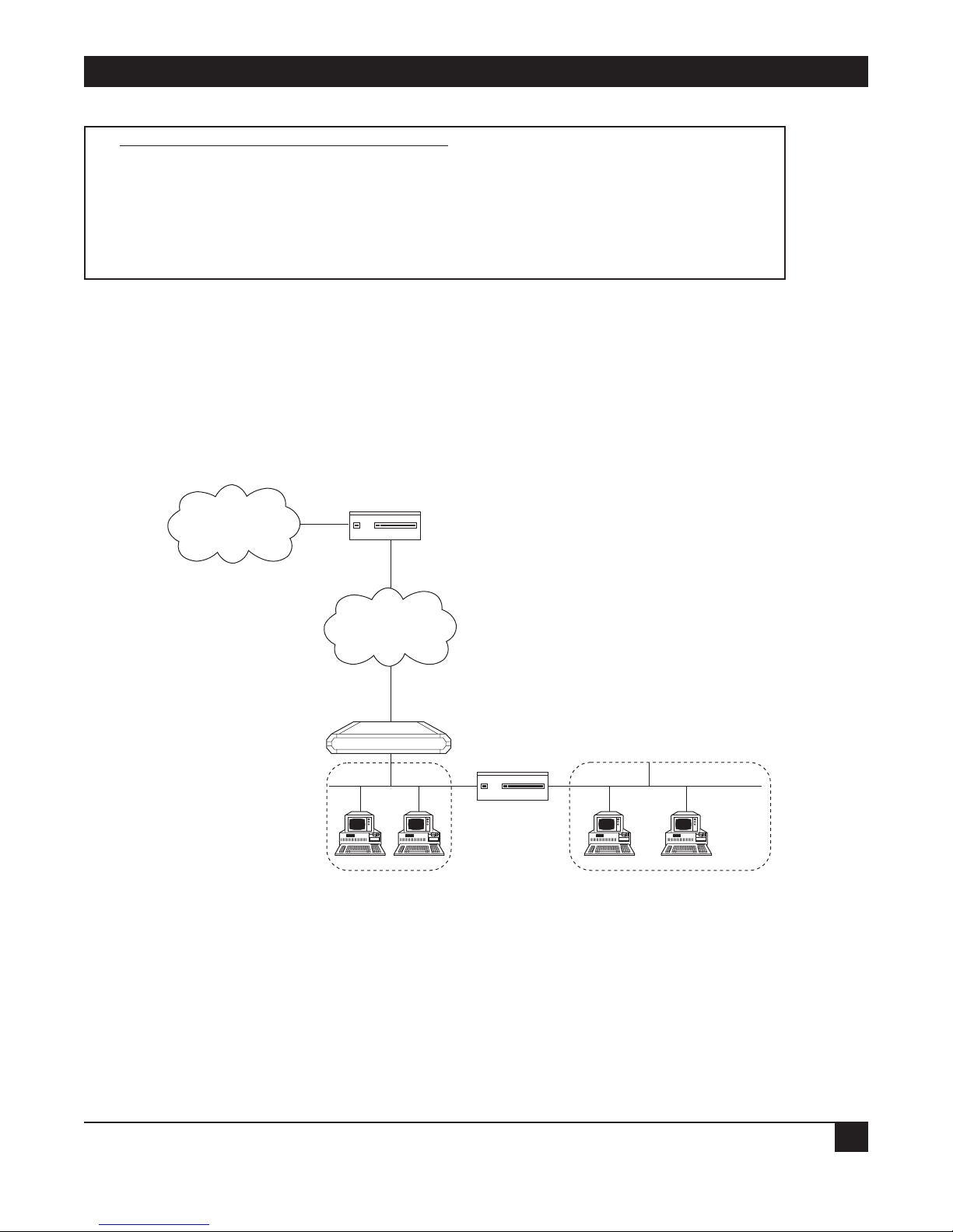
1.5.3 SINGLE IP
The Ethernet Extender can be used as a point of presence on the Internet. A home user can dial in to the
Ethernet Extender, and use the Ethernet Extender Single IP feature to access the Internet. Refer to Figure 1-6.
Figure 1-6. Ethernet Extender Using Single IP.
Internet
ISP
WAN
Home User
Solid Firewall
Single IP Enabled
Ethernet Extender
Page 16

CHAPTER 2: Configuration Introduction
13
2. Configuration Introduction
2.1 How to Start Configuring the Ethernet Extender
The Ethernet Extender can be configured as either a bridge or a router. By default, it’s configured in bridge
mode. Decide whether the Ethernet Extender will be used as a bridge or a router before you start the
configuration.
Before you configure the Ethernet Extender as a bridge, set the location switch to Remote or Main. One of the
two Ethernet Extenders in the bridge must have the location switch set to Remote and the other set to Main:
• Remote—If the Ethernet Extender you are configuring as a bridge is connected to the network that is
smaller, and has no connections via a router to other networks.
• Main—If the Ethernet Extender you are configuring as a bridge is connected to the network that is larger
or has connections via a router to other networks.
For more information, refer to the Ethernet Extender Installation and Operation Guide.
Before you configure the Ethernet Extender as a router, follow the appropriate checklists, listed below.
NOTE
If you are using the Ethernet Extender as a router, set the location switch to Main. For
more information, refer to the Ethernet Extender Installation and Operation Guide.
2.1.1 CONNECTING TO THE INTERNET/INTRANET AS A PUBLIC IP NET
Use the following check list to make sure you are ready to connect to the Internet/Intranet.
Internet Check List
• Subscribe to the Internet Service Provider (ISP) and request a static IP subnet.
• Request a dialup telephone number, your username, and your password from the ISP. Configure this into
the Ethernet Extender using the Quick Setup option. Check whether a login script is necessary to access the
ISP. If it is, call Technical Support.
• Disable the Single IP in the Ethernet Extender Quick Setup option.
• Make sure the line (ISDN, PSTN, Frame Relay, or DDS) to the ISP is working properly.
• Use the static IP subnet you have obtained to configure the LAN IP host addresses of the Ethernet
Extender.
Page 17

ETHERNET EXTENDERS—CONFIGURATION GUIDE
14
Preparing Your PCs
• Make sure your PCs have a correctly installed TCP/IP stack such as WinSock or Chameleon.
• Assign an IP address from the static IP subnet to each PC.
• Make sure that each PC has the correct subnet mask.
• Configure each PC with the Ethernet Extender as the Default Gateway.
• Configure each PC with the ISP’s DNS IP address.
• Check that your small-office LAN is correctly set up to work with IP.
2.1.2 C
ONNECTING TO THE INTERNET/INTRANET AS A PRIVATE IP NET (USING SINGLE IP)
Use the following checklist to make sure you are ready to connect to the Internet/Intranet.
Internet Check list
• Subscribe to the Internet Service Provider (ISP) and request a single subscription connection.
• Decide on a private IP net for your small-office LAN (Reference RFC 1918).
• Request a dialup telephone number, your username, and your password from the ISP. Configure this into
the Ethernet Extender using the Quick Setup option. Check whether a login script is necessary to access the
ISP. If it is, call Technical Support.
• Enable the Single IP in the Ethernet Extender Setup option.
• Make sure the line (ISDN, PSTN, Frame Relay, or DDS) to the ISP is working properly.
• Use the private IP subnet you have obtained to configure the private host addresses of the Ethernet
Extender.
• Check that your small-office LAN is correctly set up to work with IP.
Preparing your PCs
• Make sure your PCs have a correctly installed TCP/IP stack such as WinSock or Chameleon.
• Assign an IP address, unique to the LAN, to each PC.
• Configure each PC with the Ethernet Extender as the Default Gateway.
• Make sure that each PC has a correct subnet mask.
• Configure each PC with the ISP’s DNS IP address.
• Check that your small-office LAN is correctly set up to work with IP.
Page 18
CHAPTER 2: Configuration Introduction
15
2.2 Initial Setup
The Ethernet Extender features a setup program that is invoked and run from an ASCII terminal or a PC
terminal emulator. The terminal/terminal-emulator is connected to the CONTROL port on the Ethernet
Extender’s front panel.
This section describes the procedures necessary to connect to the terminal and to access the setup program’s
Main menu.
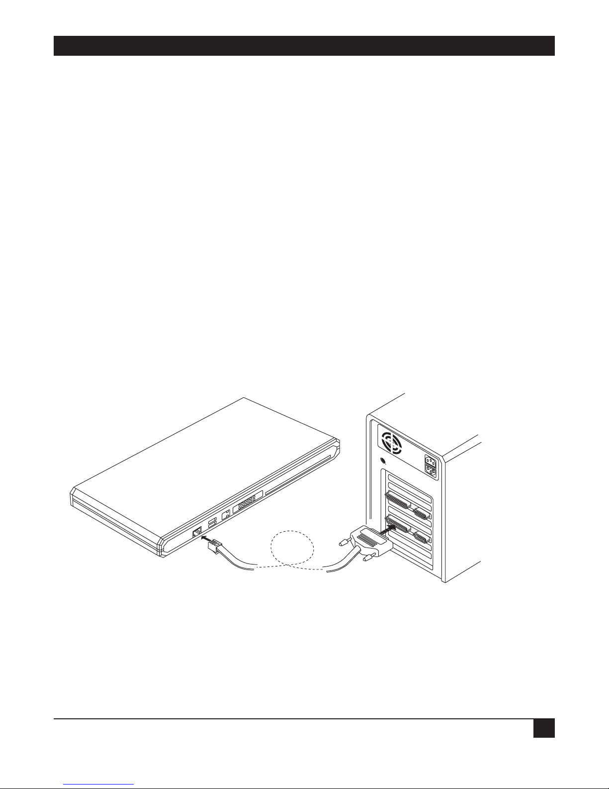
2.2.1 C
ONNECTING TO THE TERMINAL
To connect the terminal:
1. Connect a control cable between the Ethernet Extender RJ-45 CONTROL port and the connector on the
terminal; or between the Ethernet Extender RJ-45 CONTROL port and the PC communication port (refer
to Figure 2-1).
2. Set the terminal to work at any baud rate from 2.4 to 19.2 kbps, no parity, 8 data bits. The baud rate is selfadaptable.
3. Set the hardware control to OFF.
4. Switch on the Ethernet Extender. The operational status screen appears. Press ENTER several times to
invoke the password message.
Figure2-1. Connecting to the Terminal.
Page 19

ETHERNET EXTENDERS—CONFIGURATION GUIDE
16
2.2.2 SETTING A PASSWORD
For first-time operation, or if no configuration password has been specified, the following message appears:
WARNING: No configuration password exists.
Define configuration password? (Y/N):
To set a password:
1. Type Y to set a configuration password. A message appears, prompting you to enter a new configuration
password.
2. Type a password. The password can be up to twelve characters. Press the ENTER key. A message appears,
prompting you to retype the password for verification.
3. Re-type the password and press ENTER. The Main menu screen appears.
The password protects entry to the configuration module, preventing unauthorized personnel from
changing setup and configuration parameters.
NOTE
All Ethernet Extender password-verification routines are case-sensitive. Once a
password has been set, always use the same case as in the original when typing the
password. (For example, “password” and “Password” are two different passwords.)
2.2.3 CHANGING AND DELETING THE PASSWORD
To change the password during normal operation:
1. From the Main menu, select option 0, Exit, to return to the Operational Status Messages screen.
2. Press ENTER several times. You will be prompted to enter the current password.
3. Enter the current password. A message appears, asking if you want to update the current password. Type Y.
You will be prompted to re-enter the current password.
4. Re-enter the current password. A message appears prompting you to enter the new password.
5. Enter the new password, and re-enter the same password for verification. The Main menu appears.
To delete the current password:
1. Follow steps 1-5 above to change the password. When prompted to enter a new password, press ENTER
without typing a new password. This deletes the current password and removes password protection.
2. Press ENTER again when prompted for verification. The Main menu appears. If the unit doesn’t have an IP
Address, the Quick Setup menu appears.
NOTE
Use of password protection for the configuration module is recommended. Always use
the “Exit” option in the Main menu once the unit has been configured. Using the Exit
option will force personnel requiring access to the configuration module to use the
password.
Page 20

CHAPTER 2: Configuration Introduction
17
2.3 The Quick Setup Menu
The Quick Setup menu is used to define the basic parameters for your Ethernet Extender. The Quick Setup
menu allows you to adjust setup and link configuration parameters while the Ethernet Extender is in operation.
The line-by-line prompting guides you throughout the procedure. On-screen instructions and explanations
guide you through the setup procedure.
The parameters include:
• IP Parameters.
• WAN Interface.
• Security (Password) Setup.
For a complete description of the Quick Setup menu, refer to Chapter 3.
2.4 Menus and Screens
This section provides a brief description of the available Ethernet Extender menus and screens.
2.4.1 T
HE MAIN MENU
The name of the device (Ethernet Extender) connected to the terminal is listed at the top of the screen. The
Main menu has five options. To choose an option, you type the number preceding the option.
MAIN MENU ( Device name - Name )
—————
1. Quick setup
2. Security setup
3. Advanced setup
4. View
5. Diagnostic tools
0. Exit
Figure 2-2. Ethernet Extender Main Screen.
2.4.2 Q
UICK SETUP
The Quick Setup menu allows you to adjust setup and link configuration parameters while the Ethernet
Extender is in operation. Line-by-line prompting simplifies the setup. On-screen instructions and explanations
guide you through the setup procedure.
2.4.3 S
ECURITY SETUP
Use the options in the Security Setup menu to control Ethernet Extender management and entry to your LAN
by unauthorized users.
Page 21

ETHERNET EXTENDERS—CONFIGURATION GUIDE
18
2.4.4 ADVANCED MENU
The Advanced menu lists Ethernet Extender configuration parameters and their current values. You can
change these parameters and perform advanced configuration operations not available through the Quick
Setup menu. Resetting the device and software downloads are also performed via the Advanced menu.
2.4.5 V
IEW
Use the options in the View menu to view configuration screens and information on interface connections,
routing tables, and statistics.
2.4.6 D
IAGNOSTIC TOOLS
Use the Diagnostic Tools menu to verify WAN and LAN connectivity. The Ping feature allows you to dial (Ping)
another user on the LAN or WAN. If the remote user replies, WAN connectivity is confirmed up to and
including the IP level.
2.4.7 E
XIT
Select this option to return to the Operational Status Messages screen. From the Operational Status Messages
screen, you can remove or change the password.
Page 22

CHAPTER 3: Quick Setup Menu
19
3. Quick Setup Menu
The Quick Setup menu allows you to enter the minimum number of parameters needed to operate your
Ethernet Extender. You can access the Quick Setup menu via:
• ASCII terminal.
• Telnet.
For more extensive control of your Ethernet Extender, refer to Chapters 4 and 5.
3.1 Quick Setup Menu Parameters
The Quick Setup screen guides you through the configuration, port by port. The Quick Setup screen asks you
for the appropriate parameters depending on the type of port you are configuring and how you have already
configured other ports.
• To accept the current parameter, press ENTER.
• The parameter options are enclosed in brackets [ ]. To view the options, toggle with the space bar and press
ENTER.
• To enter new information, type in the new parameters and press ENTER.
After all parameters have been accepted or changed, you can view them on the screen. A confirmation message
appears requesting that you confirm all the setup changes. The device resets after the changes are saved.
To configure the setup parameters:
1. From the Main menu, select option 1, Quick Setup.
2. Follow the on-screen instructions to accept or modify the setup parameters.
3. Press Y to save the setup parameters.
Page 23

ETHERNET EXTENDERS—CONFIGURATION GUIDE
20
QUICK SETUP
—————WARNING: This device automatically exits to Operational Messages
10 minutes after last keyboard action without saving parameters
‘ENTER’ - Accept parameter , ‘SPACE’ - Change parameter .
WAN interface #1 - V.35
Connection type: [Uplink ]
Link mode: [Synchronous ]
Routing: [BRIDGE ], Protocol: [PROPRIETARY]
Connection : [Always ]
WAN interface #2 - V.24
Connection type: [Answer ]
Link mode: [Asynchronous ]
Routing: [IP ROUTER ], Protocol: [SLIP ]
WAN IP address: 0.0.0.0 , enter new : 0.0.0.0
BOOTP address: 0.0.0.0 , enter new :0.0.0.0
Modem type: Direct Connection
Do you want to change modem type (Y/N)? : [N] Baud rate: [57.6 ] Kbps
Host IP setup:
LAN IP address : 192.168.218.1 , enter new : 192.168.218.1
LAN IP mask : 255.255.255.000 , enter new : 255.255.255.000
Default gateway setting by: [Interface ]
Default gateway interface: 1
SECURITY setup
Device access name : Ethernet Extender
No password at present - do you want to create password (Y/N)? : [N]
Security type: [Disabled]
Saving the changes might cause RESET the unit.
Do you want to save QUICK SETUP (Y/N) ? Y
Figure 3-1.Quick Setup Example.
Page 24

CHAPTER 3: Quick Setup Menu
21
The fields in the Quick Setup example are described below:
3.1.1 L
INK MODE
Select this parameter to determine how data is transmitted across the link. There are three modes:
1. When the mode is synchronous, data bits are transmitted at a fixed rate. The sender and the receiver are
synchronized.
2. When the mode is asynchronous, data units are transmitted character-by-character. The characters are
preceded by start bits and followed by stop bits. The start and stop bits provide synchronization at the receiver
side.
3. Frame Relay is a packet-switching protocol for connecting devices on a WAN.
Use the space bar to switch to synchronous, asynchronous, or Frame Relay mode.
3.1.2 R
OUTING
Select this parameter to assign the link type. Use the space bar to switch to Bridge, IP, IPX, or IP & IPX.
Selecting IPX link type disables the Single IP and WAN IP Address features, and eliminates the corresponding
parameters from the screen.
3.1.3 C
ONNECTION
Select this parameter to determine when the link between the local LAN and the Internet should be activated.
Selecting upon traffic to WAN activates the link only when there is traffic to be sent on the link. Selecting
always keeps the link active independent of traffic. If you pay for your connection by the minute, selecting upon
traffic to WAN will reduce your operating costs.
Choose always or upon traffic to WAN. If you choose upon traffic to WAN, the Disconnect Timeout parameter
displays.
3.1.4 WAN IP A
DDRESS
Select this parameter to enter the IP address for the WAN interface.
3.1.5 BOOTP A
DDRESS
Select this parameter to enter the IP address for the BOOTP server.
3.1.6 M
ODEM TYPE
Select this parameter to change the modem type.
3.1.7 B
AUD RATE
Select this parameter to display the rate at which data is sent between the Ethernet Extender and the modem.
Use the space bar to run through the different baud rates. The Quick Setup default value is recommended for
your modem.
Page 25

ETHERNET EXTENDERS—CONFIGURATION GUIDE
22
Figure 3-2. Setting Baud Rate.
3.1.8 H
OST IP SETUP
LAN IP Address
Select this parameter to enter the IP address. Every device on a TCP/IP network must have an address to
identify it. The IP address is a value consisting of the network address and the host address on that network.
The value assigned to a network depends on the number of computers on that network.
The IP address is a 32-bit number. The number is made up of 4 parts, with each part consisting of 3 digits. One
part of the address identifies the network and another part of the address identifies the host. Which numbers in
the address identifies the host is dependent of the class.
There are 5 classes of IP addresses. Each class represents a network having a certain number of computers. For
example, a Class C address is given to a network having from 1 to 255 computers. Table 3-1 gives the ranges for
different classes of IP addresses.
Table 3-1. IP Classes
Class Range
A 0.0.0.0 to 127.255.255.255
B 128.0.0.0 to 191.255.255.255
C 192.0.0.0 to 223.255.255.255
D 224.0.0.0 to 239.255.255.255
E 240.0.0.0 to 247.255.255.255
The numbers in each part of the code is translated into binary. The binary code identifies the network and the
host.
IP addresses are assigned by the Internet Network Information Center (InterNIC). InterNIC assigns the
network ID. Host IDs are assigned by the network administrator.
Public Access Service
Modem
28.8 kbps
baud rate
V.24
Ethernet Extender
Page 26
CHAPTER 3: Quick Setup Menu
23
LAN IP Mask
Select this parameter to enter the IP mask. The mask is configured automatically from the IP address class. If
you want to change the default mask, enter a new mask. For example, the IP mask is usually 225.225.225.0. A
mask of this sort would allow 254 hosts on the LAN. If you want to create a subnet which allows 6 users,
including the Ethernet Extender, configure the mask as 22.225.225.248. on the Ethernet Extender and each
host that is included on the subnet. Refer to Figure 3-3.
Figure 3-3. Setting up the IP Mask.
3.1.9 SECURITY SETUP
Device Access Name
Select this parameter to display the name assigned to the Ethernet Extender for identification by the Internet
service provider. To change the device access name, type in the new name and press ENTER.
Device Access Password
Select this parameter to assign or update a password. The password is used to access the Internet.
The Ethernet Extender’s default setup does not include a password. Use the space bar to toggle between no (do
not change the password) and yes (enter a new password). If you choose yes, the following appears:
Enter new password : ***
Enter new password verification : ***
Type the new password and verify it.
Ethernet Extender
LAN IP address 192.168.1.1
Mask 255.255.255.248
IP address 192.168.1.2 .3 .4 .5 .6
Mask 255.255.255.248 .248 .248 .248 .248
Default Gateway 192.168.1.1 192.168.1.1 192.168.1.1 192.168.1.1 192.168.1.1
Page 27

ETHERNET EXTENDERS—CONFIGURATION GUIDE
24
3.2 Where To Go From Here
If you want to.. Refer to..
Prevent management of the Ethernet Extender and entry to your Chapter 4, Security Setup Menu
LAN by unauthorized users.
Change the Ethernet Extender configuration parameters and Chapter 5, Advanced Setup Menu
perform advanced configuration operations not available through
the Quick Setup menu, reset the device, or download software.
Page 28

CHAPTER 4: Security Setup Menu
25
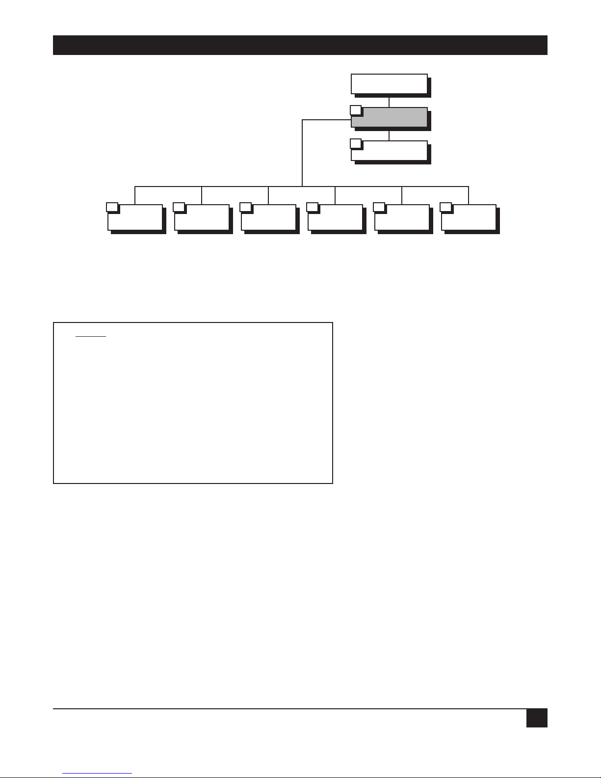
4. Security Setup Menu
Figure 4-1. Security Setup Menu Outline.
The Security Setup menu allows you to control access to the Ethernet Extender and the LAN. The Ethernet
Extender is protected against access by unauthorized users by disabling access via SNMP, TELNET, and Web
browsers. The Solid Firewall is used to protect the LAN against undesired entry.
To access the Security Setup menu:
1. In the Main menu, press 2. The following screen appears:
SECURITY SETUP ( Device name - Name )
1. TELNET access - Disabled
2. SNMP access - Disabled
3. FIREWALL options - Disabled
ESC - Return to previous menu
Choose one of the above:
Diagnostic Tools
5
View
4
Advanced Setup
3
Security Setup
2
Quick Setup
1
FIREWALL options
3
SNMP access
2
TELENET access
1
Page 29

ETHERNET EXTENDERS—CONFIGURATION GUIDE
26
4.1 Enabling TELNET Access
The Ethernet Extender supports TELNET. This allows the Ethernet Extender to be configured and controlled
over the WAN and LAN using TCP/IP.
Access to TELNET requires authentication by the device, using username and password.
By default, TELNET access to the Ethernet Extender is disabled, to prevent changes being made to the unit’s
configuration parameters.
Enabling TELNET access allows configuration of the Ethernet Extender via TELNET.
To enable TELNET access:
1. From the Main menu, select option 2, Security Setup.
2. From the Security Setup menu, select option 1, TELNET access.
TELNET access setup
‘ENTER’ - Accept parameter , ‘SPACE’ - Change parameter .
Do you want to permit TELNET management of the device ? [ Y ]
TELNET user name : lan
Do you want to change TELNET password ? [ N ]Y
Current password : ***
Enter new password : ***
Enter new password verification : ***
Do you want to save TELNET parameters (Y/N) ? Y
3. Toggle to Y.
4. Press ENTER.
5. Follow the on-screen instructions to allocate a username and password. Save the new setup.
The Ethernet Extender can now be accessed using your TELNET username and password.
Page 30

CHAPTER 4: Security Setup Menu
27
4.2 Enabling SNMP Access
By default, access to the Ethernet Extender via SNMP is disabled. Blocking SNMP access prevents changes
being made to the unit’s configuration parameters. Enabling SNMP access prompts the user to define SNMP
management parameters.
To enable SNMP access:
1. From the Main menu, select option 2, Security Setup.
2. From the Security Setup menu, select option 2, SNMP access.
3. Toggle to Y.
4. Press ENTER.
5. Enter the read, write, and trap communities. Save the new setup.
SNMP access setup
‘ENTER’ - Accept parameter , ‘SPACE’ - Change parameter .
Do you want to permit SNMP management of the device ? [ N ]Y
SNMP read community : public
SNMP write community : private
SNMP trap community : public
Do you want to save SNMP parameters (Y/N) ? Y
The Ethernet Extender can now be accessed for SNMP operation using the appropriate communities.
Page 31

ETHERNET EXTENDERS—CONFIGURATION GUIDE
28
4.3 Enabling/Disabling the Solid Firewall
Solid Firewall, when enabled, prevents all access from the WAN or Internet/Intranet into the small-office LAN.
Outgoing traffic from the LAN will be forwarded to the WAN. Incoming traffic from the WAN will be blocked
from entering the LAN. Only those applications that are enabled via the Firewall Forward Application List (for
example, Web browsing, FTP, email servers, etc.) will be allowed to enter the LAN. By default, the Solid Firewall
is disabled. In Single IP mode, Solid Firewall is always enabled by default and cannot be disabled.
To enable the Solid Firewall feature (in regular router mode):
1. From the Main menu, select option 2, Security Setup.
2. From the Security Setup menu, select option 3, Firewall Options.
FIREWALL options setup
Enabling FIREWALL will forward outgoing sessions
from LAN to WAN and block incoming sessions from
entering the LAN except for applications that are
enabled by the FIREWALL FORWARD APPLICATION LIST.
Do you want to enable firewall options ? [ N ]Y
Enter link from which to be protected by FIREWALL: 1
3. Toggle to Y and press ENTER to enable the Solid Firewall and get the Firewall Forward Application List
screen.
4. Press ESC and save the Firewall setup to block all incoming traffic from the WAN.
Page 32

CHAPTER 4: Security Setup Menu
29
To enable a specific application to enter the Solid Firewall (both in regular router and Single IP modes)
1. In the Firewall Forward Application List screen, press A to add an application.
FIREWALL FORWARD APPLICATION LIST ( Device name - Name )
List of applications which may pass the FIREWALL.
APPLICATION ADVANCED SETUP IP ADDRESS
1. TELNET server NO 194.090.182.040
2. PING request NO 194.090.182.040
Telnet server, Ping request, DNS server, E_Mail POP3, E-Mail SMTP,
FTP server, WWW server, TFTP server, SNMP, User defined
Application type: [E-MAIL POP3 ] [Default ] Advanced
Host IP address interval: [SINGLE ]
Host IP Address: 194.90.182.39
Guest IP address interval: [INTERVAL ]
Guest start IP Address: 194.90.182.30
Guest end IP Address: 194.90.182.40
Host port interval: [SINGLE ]
Host port: 110
Guest port interval: [ALL ]
Frame type: [TCP ]
2. To select an application, toggle the SPACE bar.
3. If a specific application has a specific IP destination on the LAN, select DEFAULT and type the IP
destination address.
4. The advanced option includes the following possibilities for forwarding an IP session to the secured LAN:
• Host IP address interval—range of destination addresses on the LAN (only one address for Single IP).
• Guest IP address interval—range of source addresses in the Internet/Intranet.
• Host port interval—range of UDP or TCP destination ports of the applications.
• Guest port—range of UDP or TCP source ports of the applications.
• Frame type—UDP, TCP, or ICMP protocol. Select Single, All, or Interval and type the IP address for
each option listed above.
5. Press ESC and save the Firewall setup.
NOTE
In Single IP mode, for each application, only one destination address from the secured
LAN can be used. Incoming traffic from the WAN should be destined to the single IP
address. The Ethernet Extender forwards the application to the destination address on
the LAN, as listed in the Firewall Forward Application List.
Page 33

ETHERNET EXTENDERS—CONFIGURATION GUIDE
30
5. Advanced Setup Menu
The Advanced menu contains the majority of Ethernet Extender configuration parameters. These parameters
can be used to configure the Ethernet Extender in great detail. You can change these parameters and perform
advanced configuration operations not available through the Quick Setup menu. You can also reset the
Ethernet Extender and download software.
Figure 5-1. Advanced Menu Outline.
5.1 Advanced Menu and Setup Menu
To access the Advanced menu:
In the Main menu, press 3. The Advanced menu appears.
ADVANCED
MENU (Device name — Name)
1. Setup
2. Device control
ESC — Return to previous menu
Choose on of the above:
Figure 5-2. Ethernet Extender Advanced Menu.
The options in the Advanced menu are described below.
Setup: Select this option to modify setup parameters.
Device Control: Select this option to download the software, perform reset operations, and choose a terminal
type.
Device Control
2
Setup
1
Advanced Menu
Page 34
CHAPTER 5: Advanced Setup Menu
31
Figure 5-3. Setup Menu Outline.
To access the Setup menu:
In the Advanced menu, press 1. The Setup menu appears.
SETUP
(Device name — Name)
1. Host parameters
2. Routing/Bridging
3. Interface parameters
4. Access control (Security)
5. WAN economy
6. Factory-default options
ESC — Return to previous menu
Choose one of the above:
The options in the Setup menu are briefly described below. For a detailed description of the sub-menus, refer
to the sections that follow.
H
OST PARAMETERS
Select this option to enter reference information about the device, the IP Host, the SNMP agent, and TFTP.
R
OUTING/BRIDGING
Select this option to enter routing or bridging information for the device.
I
NTERFACE PARAMETERS
Select this option to set link, ISDN, or Frame Relay parameters.
A
CCESS CONTROL (SECURITY)
Select this option to perform security operations.
Device Control
2
Setup
1
Advanced Menu
Host
Parameters
1
Routing/Bridging
2
Interface
Parameters
3
Access
Control (Security)
4
WAN
Economy
5
Factory
Default Options
6
Page 35

ETHERNET EXTENDERS—CONFIGURATION GUIDE
32
WAN ECONOMY
Select this option to reduce traffic over the WAN and to keep the link up only when necessary.
F
ACTORY-DEFAULT OPTIONS
Select this option to return settings to the factory default.
Figure 5-4. Host Parameters Menu Outline.
To access the Host Parameters menu
1. In the Advanced menu, press 1. The Setup menu appears.
2. In the Setup menu, press 1. The Host Parameters menu appears.
HOST PARAMETERS
(Device name — Name)
1. Device ID
2. IP host
3. SNMP manager table
4. TFTP
5. RADIUS
ESC — Return to previous menu
Choose one of the above:
Device Control
2
Setup
1
Advanced Menu
Device Control
1
IP Host
2
SNMP
Manager Table
3
TFTP
4
RADIUS
5
1. Device Name 1. IP Address 1. Manager Table
1. File Server IP
Address
1. Radius Server
IP Address
2. Contact Person
2. IP Mask
2. File Name
2. Radius
Authenticator
3. System
Location
3. Default
Gateway
3. Retransmitting
Timeout
3. Radius
Accounting
System Type
4. Mac Address
4. Total Timeout
4. Retransmission
Timeout
5. Total Timeout
Page 36

CHAPTER 5: Advanced Setup Menu
33
The options in the Host Parameters menu are described below.
D
EVICE ID
Select this option to view and/or modify the following arbitrary parameters.
Device Name
Select this parameter to assign an arbitrary name to Ethernet Extender for identification by the system
manager; for example, “Accounting.”
Contact Person
Select this parameter to enter the name of the person to be contacted with matters pertaining to the system; for
example, “John Doe.”
System Location
Select this parameter to enter the physical location of the device; for example, “Building 3 Floor 4.”
MAC Address
Select this parameter to assign a MAC address locally. This allows you additional control of the devices in the
LAN. The Ethernet Extender can be used with the burned-in (default) address provided by the manufacturer
or with a locally administered address; for example, 4020 2D16 123.4. Locally administered addresses are very
useful for managing large networks.
IP H
OST
Select this option to configure the following IP parameters.
IP Address
Every device on a TCP/IP network must have an address to identify it. The IP address is a value consisting of
the network address and the host address on that network. The value assigned to a network depends on the
number of computers on that network.
The IP address is a 32-bit number. The number is made up of 4 parts, with each part consisting of 3 digits. One
part of the address identifies the network and another part of the address identifies the host. Which numbers in
the address identify the host depends on the class.
There are 5 classes of IP addresses. Each class represents a network having a certain number of computers. For
example, a Class C address is given to a network having from 1 to 255 computers. Table 5-1 gives the ranges for
different classes of IP addresses.
Table 5-1. IP Classes
Class Range
A 0.0.0.0 to 127.255.255.255
B 128.0.0.0 to 191.255.255.255
C 192.0.0.0 to 223.255.255.255
D 224.0.0.0 to 239.255.255.255
E 240.0.0.0 to 247.255.255.255
The numbers in each part of the code are translated into binary. The binary code identifies the network and
the host.
Page 37

ETHERNET EXTENDERS—CONFIGURATION GUIDE
34
IP addresses are assigned by the Internet Network Information Center (InterNIC). InterNIC assigns the
network ID. Host IDs are assigned by the network administrator.
IP Mask
A subnet is a portion of a network that shares a common address component. On TCP/IP networks, subnets
are defined as all devices whose IP addresses have the same prefix. For example, all devices with IP addresses
that start with 133.100.100. would be part of the same subnet. An IP mask allows filtering of IP addresses on a
subnet.
When an IP address is configured, the IP mask is automatically configured according to the following table:
IP Network Class IP Address Range Default IP Mask
A 0.0.0.0–125.255.255.255 255.0.0.0
B 128.0.0.0–191.255.255.255 255.255.0.0
C 192.0.0.0–223.255.255.255 255.255.255.0
D 224.0.0.0–239.255.255.255 255.255.255.255
The default IP mask can be edited.
Default Gateway
The default gateway is the address to which frames are sent if no other address is defined in the routing table.
The station compares the destination IP address net ID with the station’s own net ID. If they are not the same,
the Ethernet Extender automatically sends the packets to the default gateway MAC address—in this case, the
Ethernet Extender. The Extender then passes the packets to the Central Access Router link. From there they
are routed onward.
The default gateway can be an IP address or a WAN interface. If you choose to use an IP address, enter the
address of the router which will deliver the frames. Specifying an IP address for the default gateway is done with
shared media, such as LAN interface.
If you choose to use a WAN interface, the connection to the router is point-to-point. Choose “by interface” and
Interface 1 is automatically set.
Figure 5-5. Default Gateway.
LAN interface IP address
should be Default Gateway
for all stations on LAN
Ethernet Extender
Central Access Router
Internet
Page 38

CHAPTER 5: Advanced Setup Menu
35
NOTE
It is very important to obtain the correct parameters from the system administrator or
ISP. The most common problem when establishing an IP connection is incorrect
configuration of the IP parameters and default gateway. Do not try to guess these
parameters.
SNMP MANAGER TABLE
Select this option to add, clear, or delete parameters from the manager table. The manager table lists the SNMP
manager IP addresses and masks.
Simple Network Management Protocol (SNMP) is an application-layer protocol designed to facilitate the
exchange of management information between network devices. By using SNMP to access management
information data (such as packets per second and network error rates), network administrators can more easily
manage network performance and find and solve network problems.
TFTP (T
RIVIAL FILE TRANSFER PROTOCOL)
TFTP is a file transfer protocol used for downloading boot code to diskless workstations.
TFTP is used in a server designated as the TFTP server. The server needs to provide concurrency to allow
multiple users to boot up simultaneously. To do this, TFTP creates a UDP port for each client. By creating a
UDP port, the different client input datagrams can be demultiplexed by the server’s UDP module.
Demultiplexing in the module increases the server efficiency.
One characteristic of TFTP is that it is not secure. There is no password or firewall associated with TFTP.
Anyone with the IP address of the TFTP server can enter the server and download files. Security can be
provided by creating a directory which contains only those files which you want to be downloaded. This
prevents access to any other files.
You must configure the following parameters in a TFTP server:
File Server IP Address
Select this parameter to enter the IP address of the TFTP server; for example, 192.168.10.11.
File Name
Select this parameter to enter the name and path of the file to be transferred; for example, c:\booting\boot.exe.
Retransmitting Timeout
Select this parameter to enter the amount of time that is allowed to pass before a file is retransmitted; for
example, 30 seconds.
Total Timeout
Select this parameter to enter the amount of time the Ethernet Extender should wait for an acknowledgment
from the TFTP server; for example, 60 seconds.
Page 39

ETHERNET EXTENDERS—CONFIGURATION GUIDE
36
Figure 5-6. File Transfer to and from TFTP Server.
RADIUS A
UTHENTICATION AND BILLING
The Remote Authentication Dial-In User Service (RADIUS) is a client/server security protocol. Security
information is stored in a central location, known as the RADIUS server. RADIUS clients, such as the Ethernet
Extender, communicate with the RADIUS server to authenticate users. Although the term RADIUS refers to
the network protocol that the client and server use to communicate, it is often used to refer to the entire
client/server system.
The three main functions of RADIUS are authentication, authorization, and accounting. To perform these
functions, you must configure the following parameters:
Figure 5-7. Setting up the RADIUS Server.
TFTP Server
IP Address: 192.168.10.11
Holds file at C:\booting\boot.exe
Ethernet Extender
File Transfer
RADIUS Server IP address 192.168.1.9
LAN IP address 192.168.1.1
User Name/Password
Page 40

CHAPTER 5: Advanced Setup Menu
37
RADIUS Server IP Address
Select this parameter to enter the IP address of the RADIUS server; for example, 192.168.1.9.
In addition, select this parameter to enable/disable accounting.
RADIUS Authenticator
Select this parameter to enter the shared secret. The shared secret is a password used by RADIUS to
authenticate the client. It is important to remember that the client is the Ethernet Extender. The user is not
requested to supply the shared secret.
NOTE
When configuring the RADIUS Authenticator, be sure to use the same value in the
RADlUS server and Ethernet Extender.
RADIUS Accounting System Type
Select this parameter to track link up/link down activity. This information is often used for billing purposes.
Use the space bar to toggle between ON and OFF.
Retransmission Timeout
Select this parameter to enter the maximum time the Ethernet Extender waits for a response from the RADIUS
server; for example 30 seconds.
Total Timeout
Select this parameter to enter the total time the Ethernet Extender tries to communicate with the Radius server.
Figure 5-8. Routing/Bridging Menu Outline.
Device Control
2
Setup
1
Advanced Menu
Link
Routing/Bridging
Mode
1
Static
Station
and Nets
2
IP Routing
Setting
3
IPX Routing
Setting
4
RADIUS
5
1. Link Type Add
1. Interface
Address
New Stations
Ageing Time
Link Number
Routing/Bridging
2
2. Link
Protocol
Clear 2. RIP Mode
3. Link
Cost/Metric
Delete
3. Maximum
Transmit Unit
4. PPP Setting
4. PC Remote
Access
1. Header and
Control Field
Compression
1. Shared
IP Net
2. Protocol Field
Compression
2. Remote
Workstation IP
Address Allocation
3. IP Compression
(V. Jacobson-
RFC1144)
3. Remote
Workstation IP
Address Pool
4. Data
Compression
Mode (RFC-1974
Compatible)
4. Primary
Domain Name
Server
5. Multilink
5. Secondary
Domain Name
Server
Page 41

ETHERNET EXTENDERS—CONFIGURATION GUIDE
38
To access the Routing menu:
In the Advanced menu, press 1. The Setup menu appears.
In the Setup menu, press 2. The Routing menu appears.
ROUTING
(Device name — Name)
Link 1 - IP & IPX ROUTER PPP
Link 2 - IP ROUTER SLIP
Setup Menu
1. Link Routing/Bridging mode
2. Static stations & nets
3. IP routing settings
4. IPX routing settings
5. Station ageing (minutes): 30
ESC — Return to previous menu
Choose one of the above:
The options in the Routing menu are described below.
L
INK ROUTING/BRIDGING MODE
Link Type
Select this parameter to assign the link type. Use the space bar to choose Bridge, IP, IPX, or IP & IPX routing.
Figure 5-9. Routing Modes.
Ethernet Extender
Routing/Bridging Mode:
• Bridge
• IP
• IPX
• IP/IPX
Central Access Router
Page 42

CHAPTER 5: Advanced Setup Menu
39
Link Protocol
Select this parameter to assign the link protocol. Link protocols available for asynchronous link are: SLIP,
CSLIP, or PPP.
• SLIP — SLIP stands for Serial Line Internet Protocol. It is a simple form of encapsulation for IP datagrams
on serial lines. SLIP is often used in connecting home systems to the Internet, through the RS-232 serial
port. The following rules specify the framing used by SLIP. The IP datagram is terminated by the END
character (0xc0). Most datagrams transmit an END character at the beginning of a datagram as well.
Placing an END at the beginning prevents interpreting line noise as being part of the datagram. Any data
before the END character is removed and erased.
• If a byte of the IP datagram equals the END character, the 2-byte sequence 0xdb, 0xdc is
transmitted instead. This special character, 0xdb, is called the SLIP ESC character. (This is not
the same as the ASCII ESC character.
• If a byte of the IP datagram equals the SLIP ESC character, the 2-byte sequence is transmitted
instead.
SLIP has several drawbacks:
• Each end must know the other’s IP address. There is no method for one informing the other of
its IP address.
• There is no type field. If a serial line is using SLIP, the line cannot be used for some other
protocol.
• There is no checksum added by SLIP. If a noisy phone line corrupts a datagram being transferred
by SLIP, the higher levels must detect the corruption.
SLIP is specified in RFC 1055.
• CSLIP — CSLIP stands for Compressed Serial Line Internet Protocol. CSLIP is used to solve a problem
associated with SLIP. SLIP lines are often slow (19200 bits/second or less). They are often used for
interactive traffic, such as Telnet, which uses TCP. TCP adds many small packets to the data. To carry 1 byte
of data requires a 20-byte IP header on a 20-byte TCP header, an overhead of 40 bytes. To overcome this
drawback, CSLIP reduces the header from 40 bytes to 3 or 5 bytes. By reducing the header size, response
time is improved. CSLIP maintains the state of up to 16 TCP connections on each end of the CSLIP link.
CSLIP is specified in RFC 1144.
• PPP — PPP stands for Point-to-Point Protocol. PPP consists of 3 components:
• A way to encapsulate IP datagrams on a serial link. PPP supports either an asynchronous link with
8 bits of data and no parity, or bit-oriented synchronous links.
• A link control procedure (LCP) to establish, configure, and test the data-link connection. Having
an LCP allows each end to negotiate various options.
• A family of network control protocols (NCPs) specific to different network-layer protocols. The
NCPs allow each end to configure network control parameters.
Page 43

ETHERNET EXTENDERS—CONFIGURATION GUIDE
40
Each frame begins and ends with a flag byte whose value is 0x7e. The flag byte is followed by an address byte
whose value is Oxff. The address byte is followed by a control byte whose value is 0x03.
The control byte is followed by the protocol field. The value of the protocol field determines the type of
information field. A value of 0x0021 means the information filed is an IP datagram. A value of 0xc21 means
that the information field is link control data, and a value of 0x8021 means that the information field is for
network control data. The CRC field is a cyclic redundancy check, used to detect errors in the frame.
PPP is often used across slow serial lines. It is therefore important to reduce the number of bytes per frame
to reduce the latency time. Using the LCP, most implementations negotiate to omit the constant address
and control fields and to reduce the size of the protocol fields from 2 bytes to 1 byte. In addition, when
using the IP NCP, most implementations use Van Jacobson header compression to reduce the size of the IP
and TCP headers.
Link protocols available for synchronous or ISDN links are: PPP or Native.
Figure 5-10. Link Protocols.
Link Cost/Metric
Select this parameter to assign a cost to each WAN link for routing purposes.
Metrics are hop counts. Hop counts are the number of routers through which a packet must go to get to its
destination. Adjacent interfaces have a hop count of 1. If a packet must go through 2 routers to get to its
destination, the hop count is 2. The higher the hop count, the longer the route.
A router will automatically send packets using the lowest possible metric. If a router is not functioning, the
Ethernet Extender will send the packets through an interface with a higher metric.
Protocol:
•PPP
• SLIP
• CSLIP
Central Access
Router
Ethernet Extender
Page 44

CHAPTER 5: Advanced Setup Menu
41
PPP Settings
This option is only available for PPP link protocol.
The PPP Setting screen has the following options:
• Header and Control Field Compression—This parameter is used for troubleshooting only. Do not change
the entry unless there is a problem.
• Protocol Field Compression—This parameter is used for troubleshooting only. Do not change the entry
unless there is a problem.
• IP Compression—This parameter activates Van Jacobson TCP Header Compression on a specified link.
PPP is normally used on slow bandwidths, such as modems. Data transmission is therefore slower when
using this protocol. To quicken the transmission, certain parts of the data packets can be compressed. In
Van Jacobson TCP Header Compression the packet header is compressed. Every IP data packet contains a
header. The header contains the source address, destination address, and other information.
Since PPP is used for point-to-point transmissions, both the local and remote devices must have Van
Jacobson TCP Header Compression enabled for compression to be performed. To verify that Van Jacobson
TCP Header Compression is being performed, open the Interface Connections Screen (refer to Chapter
6).
• Data Compression Negotiation Mode—the Ethernet Extender supports IP and IPX data compression
according to RFC 1974 using the STAC Compression Method. The following modes are supported:
• Disabled.
• No History.
• Sequence.
• Extended.
When the Ethernet Extender attempts to negotiate with another unit, a message is sent stating in which
mode the data will be sent. If the mode is acceptable to the receiving unit, data transmission begins. If the
mode is not acceptable (in other words, if the second unit does not support this mode), another mode is
tried, until an acceptable mode is found. This process is called auto-negotiation. When you choose a mode,
you are choosing the first mode used during auto-negotiation. Do not change this parameter unless a
problem arises with the auto-negotiation. If a problem does arise, consult the opposite unit’s user manual.
Figure 5-11. Auto-Negotiation.
Ethernet Extender
Data compression
set at LCB
Auto-Negotiation
Data compression
set at Extended
Page 45

ETHERNET EXTENDERS—CONFIGURATION GUIDE
42
In Figure 6-10, the Ethernet Extender data compression is set at LCB. In the remote unit the data
compression is set to Extended. Messages are sent between the 2 units, until a common data compression
mode is found.
• Multilink—This parameter determines if a line supports multilink PPP. You may choose between:
• Disabled—The line does not support multilink PPP.
• Bandwidth on Demand (BOD)—The first ISDN line functions according to the COD configuration.
Refer to Connection on Demand for more information. The second line is connected when the
traffic on the first line exceeds a set threshold. This option is available for ISDN only. Refer to Figure
5-12.
• Permanent—Both ISDN channels function simultaneously according to the Connection on Demand
parameters. Refer to Connection on Demand for more information.
Both BOD and Permanent setup enable multilink PPP support to this link.
Figure 5-12. Bandwidth on Demand.
Fine Tuning BOD
If you choose BOD, there are 2 parameters to configure:
• Sensibility Direction—Select this parameter to define the traffic direction to be counted in determining
whether to connect the second line. The direction can be:
• Transmit.
• Receive.
• Both.
• Sensibility Timeout—Select this parameter to define the time interval for the utilization count.
B2 B2
B1
B1
Ethernet Extender
ISDN
ISP
Internet/Intranet
Page 46
CHAPTER 5: Advanced Setup Menu
43
STATIC STATIONS AND NETS
STATIC STATIONS AND NETS (IP, IPX) (Device name — Name)
1. IP - 194.090.182.056 mask-255.255.255.248 interface-2/16 cost-1
2. IPX - 19490182 interface-3 cost-1
A - Add, C - Clear all, D - Delete
Esc - Return to previous menu.
Select this parameter to add, delete, or clear static entries in the IP/IPX Routing table. When adding, static
entries can be defined in several ways:
• IP Net—IP Net defines a network as the destination. IP Net consists of 2 parts: the frame pathway and
destination. The pathway is specified either as an interface number (meaning a port number) or as Next
Hop IP address. Next Hop IP means that the frames are sent to another router; from there they will be sent
to their final destination. To define the destination enter the subnet IP address and IP mask. For example,
194.90.182.32 is a subnet IP address and 255.255.255.240 is the IP mask.
Figure 5-13. Router 2 set to “Next Hop” in the Ethernet Extender.
• IP Station—IP Station defines a single host as the destination. IP Station consists of 2 parts: the frame
pathway and destination. The pathway is specified as in IP Net, above. To define the destination enter the
host IP address; for example, 194.90.182.1 1.
• IPX Net—IPX Net is used for IPX routing. Define the IPX Net and the interface number in hexadecimal.
• MAC—MAC is used in the remote device for Bridging. MAC defines the MAC address of the static station in
the bridge station list.
Address 194.90.182.32
Mask 255.255.255.240
IP NET 1
IP NET 2
Router 2
Ethernet Extender
ISP Router
Internet
WAN
Page 47
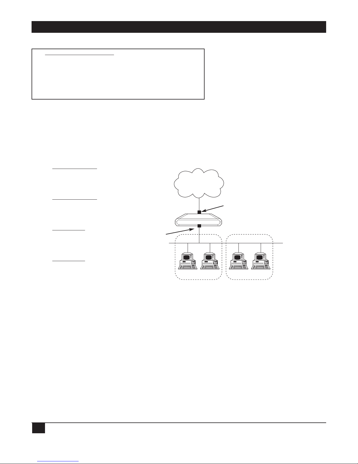
ETHERNET EXTENDERS—CONFIGURATION GUIDE
44
IP ROUTING SETTINGS
IP ROUTING SETTINGS (Device name — Name)
1. Interface address
2. RIP mode
3. Maximum transmit unit
4. PC remote access
Interface Address
Select this parameter to enter an IP address for the WAN interface and one or more IP addresses for the LAN
interface. Multiple IP addresses on the LAN are useful in environments with multiple IP nets on the LAN (refer
to Figure 5-14).
Figure 5-14. WAN and LAN Interface Addresses.
RIP Mode
Select this parameter to set the type of RIP to be sent. Choose RIP1, RIP2, RIP1+2, or No RIP for each
interface. Since most Internet applications don’t use RIP, the default setting is No RIP.
RIP stands for Routing Information Protocol. Every router has a routing table which directs packets. A router
uses the routing table to send the packets through a designated gateway (if the packet was sent to another
network) or sends the packets directly to a host. The routing table is built when the host is booted up. RIP
sends a request to all active interfaces, asking for the others’ routing table. Using the information received, the
host builds its own routing table in which the packet destinations are entered. Refer to Figure 5-15.
1. Regular Router Mode
None (“un-numbered”)
configured by setting
0.0.0.0 in Quick Setup
menu under WAN IP
Address option.
2. Regular Router Mode
Predefined (“numbered”)
configured by setting
a.b.c.d. in Quick Setup
menu under WAN IP
Address option.
3. Single IP Mode
Predefined (“Fixed IP
address”) configured by
setting a.b.c.d. in Quick
Setup menu under WAN IP
Address option.
4. Single IP Mode
None (“Dynamic IP
address”) configured by
setting 0.0.0.0. in Quick
Setup menu under WAN IP
Address option. (IP
address is received
dynamically over the WAN
using IPCP.)
IP NET 1
IP NET 2
LAN
Ethernet Extender
WAN IP Address
LAN IP Address
WAN
Page 48

CHAPTER 5: Advanced Setup Menu
45
By sending requests for information, RIP both builds the table and updates the entries. RIP updates the table
using the responses received every 30 seconds.
If a router is not functioning, the packets must be redirected and sent to a second router. The routing table
contains the address of a backup router. RIP informs all of the other routers in a network on how to go around
the non-functioning router.
Figure 5-15. Routers Exchanging Routing Tables.
Maximum Transmit Unit
Select this parameter to set the maximum transmit unit (MTU) for IP fragmentation. The MTU must be set for
each interface.
Both Ethernet and 802.3 encapsulation have frame size limits. If a frame is larger than the MTU, IP fragments
the frame into smaller units.
PC Remote Access
PC Remote Access
(Device name — Name)
1. Shared IP net - 194.090.182.032 mask - 255.255.255.240
2. Remote workstation IP address allocation (BOOT/IPCP) - Enabled]
3. Remote workstation IP addresses pool
4. Primary domain name server (DNS) - 194.090.182.034
5. Secondary domain name server (DNS) - 194.090.001.005
ESC - Return to previous menu
Choose one of the above:
Select this parameter to define the remote access. The PC Remote Access Option is important if the Ethernet
Extender is used as a remote access server for remote PCs accessing the LAN.
Shared IP Net—Select this parameter to enter the Shared IP net address. The Shared IP net address is used by
all remote workstations connecting to the remote access server on the WAN links.
Remote Workstation IP Address Allocation—Select this parameter to enable or disable allocation of remote
workstation IP addresses via BootP or IPCP negotiations.
Remote Workstation IP Address Pool—Select this parameter to enter and display a pool of addresses to be
allocated by the remote access server to remote workstations connected over the WAN links. These addresses
belong to the Shared IP Net.
A DCB
Ethernet ExtenderEthernet Extender
Central Access
Router
Central Access
Router
Page 49

aETHERNET EXTENDERS—CONFIGURATION GUIDENAME
46
Primary Domain Name Server (DNS)—Select this parameter to enter a primary DNS to be obtained by the
remote PC during the IPCP negotiations.
Secondary Domain Name Server (DNS)—Select this parameter to enter a secondary DNS to be obtained by the
remote PC during the IPCP negotiations.
DNS is a distributed database that is used by TCP/IP applications to map between host names and addresses,
and to provide electronic mail routing information. The term distributed is used because no single site on the
Internet knows all of the information. Each site (university department, company etc.) maintains its own
database and runs a server program that other systems across the Internet can query. The DNS provides the
protocol that allows clients and servers to communicate with each other.
IPX Routing Settings
IPX ROUTING
SETTINGS (Device name — Name)
1. Learn LAN IPX nets for all frame types - [Automatic]
2. LAN IPX net for frame type 802.3 - 000A8023
3. LAN IPX net for frame type Ethernet II - 04FD9F16
4. LAN IPX net for frame type 802.2 - 000A8022
5. LAN IPX net for frame type SNAP - 05FD9F16
6. Dial-in IPX net - D2FD9F16
7. RIP/SAP mode
ESC - Return to previous menu
Choose one of the above:
Select this parameter to specify how the Ethernet Extender learns IPX Nets. The Ethernet Extender can learn
IPX Nets in 3 ways:
• Learn LAN IPX Nets for all Frame Types—If you set this parameter to Automatic, the Ethernet Extender
learns IPX Nets from RIP/SAP frames sent by other IPX routers on the same LAN. Refer to Figure 5-16. If
there are no other IPX routers on the Ethernet Extender LAN, this parameter must be set to Manual, and
you must configure the IPX Nets for each frame type.
Figure 5-16. Automatic Learning from IPX Frames.
Ethernet Extender
LAN
IPX Frames
IPX Frames
IPX Frames
IPX Router
IPX Router
IPX Router
Page 50

CHAPTER 5: Advanced Setup Menu
47
• LAN IPX Net for Frame Type—Each of these parameters specifies the IPX Nets associated with a particular
frame type. Each frame type is supported by the LAN. The Ethernet Extender supplies default values for
these frame types.
• Dial-in IPX Net—This parameter specifies the IPX Net definition for a WAN interface.
RIP/SAP Mode
RIP/SAP MODE SETUP
(Device name — Name)
1. Link 1 RIP/SAP mode: [Enabled]
2. LAN RIP/SAP mode: [Enabled]
ESC - Return to previous menu
Choose one of the above:
Link I RlP/SAP Mode
Select this parameter to Enable/Disable the RIP/SAP mode. The default setting enables sending RIP and SAP
tables for all updates and interfaces (Link and LAN).
When disabled, the Ethernet Extender does not send RIP/SAP frames. The Ethernet Extender receives and
processes RIP/SAP frames sent from other routers.
S
TATION AGING
Station aging determines the amount of time a station is allowed to be inactive before it is removed from the
network. A station is inactive when no IP traffic is forwarded or received to the Ethernet Extender LAN
interface. For example, in Figure 5-17, IP address 192.18.1.1 has an aging time of 120 seconds. If no frames are
received from IP address 192.18.1.1 within 120 seconds, the station will be removed from the Ethernet
Extender IP net table.
Figure 5-17. Station Aging.
Station Aging
120 seconds
IP address 192.18.1.1
Ethernet Extender
Page 51

NAME
48
Interface Parameters
Figure 5-18. Interface Parameters Menu Outline.
To access the Interface Parameters menu:
In the Advanced menu, press 1. The Setup menu appears.
In the Setup menu, press 3. The Interface Parameters menu appears.
INTERFACE
PARAMETERS (Device name — Name)
1. Link settings
2. ISDN protocol settings
3. Frame relay DLCI settings
4. X.25 module setting
ESC - Return to previous menu
Choose one of the above:
Device Control
2
Setup
1
Advanced Menu
Link Setting
1
ISDN
Protocol Setting
2
Frame Relay
DLCI Setting
3
X.25 Module
Setting
4
1. Status
1. ISDN Protocol
& SPID
Interface
Parameters
3
2. Type
3. Connection
Type
4. Connection
Timeout (sec)
5. Control
Signals Mode
6. Baud Rate
(Kbps)
7. Parity
8. Stop Bit
9. Modem Setting
1. Asynchronous
2. Synchronous
3. ISDN
4. X.25
5. Frame Relay
1. Modem Name
2. Modem
Initialization
String
3. Autobauding
to Modem Speed
4. Reset Modem
Before Setup
5. Analyze
Modem Answer
6. Modem
Speaker On
7. Modem
Dialing Number
8. Local Number
(for Dialback)
9. Number of
Rings Before
Answer
Page 52

CHAPTER 5: Advanced Setup Menu
49
The options in the Interface Parameters menu are described below.
L
INK SETTING
Figure 5-19. Link Settings.
Status
Select this parameter to specify the status of a link: enabled or disabled. An enabled link transmits frames.
Normally you would want all links enabled. If a router is not working, however, the link to that router should be
disabled. All frames are then rerouted.
Type
Select this parameter to specify the type of interface in use: Asynchronous, Synchronous, X.25, or ISDN. For a
DDS or 4-wire link interface, the only link types available are Synchronous or Frame Relay.
1. When the mode is synchronous, data bits are transmitted at a fixed rate. The sender and the receiver are
synchronized.
2. When the mode is asynchronous, data units are transmitted character-by-character. The characters are
preceded by start bits and followed by stop bits. The start and stop bits provide synchronization at the receiver
side.
3. Frame Relay is a packet-switching protocol for connecting devices on a WAN.
Connection Type
Select this parameter to specify the type of connection:
• Originate only—If the link is to be used to connect to the Internet or Intranet.
• Answer only—If the link is to be used for receiving remote access connections.
• Answer&Originate—If the link is to be used for both incoming and outgoing connections (not
simultaneously).
Connection Timeout (sec)
Select this parameter to specify the connection timeout. The remote side has to answer within the time allotted
by the Connection Timeout. If within this time there is no response, you are informed that the remote side is
no longer active.
Connection timeout is only configured when the PPP protocol is used. The parameter consists of two parts:
• Time (1 to 255 seconds).
• Number <N> of attempts.
Ethernet Extender
Link
Page 53

ETHERNET EXTENDERS—CONFIGURATION GUIDE
50
Within the designated time, the Ethernet Extender will send frames <N> times. For example, if the time is
configured to 120 and the number is configured to 6, every 20 seconds a frame is sent. If there is no response,
the Ethernet Extender assumes that the remote unit has failed.
Figure 5-20. Connection Timeout.
Control Signals Mode
The Ethernet Extender can be set to ignore or acknowledge the following control signals: RTS (Request to
send), CTS (Clear to send), and CD (Carrier Detect). This parameter is only relevant to asynchronous
connections to dial-up modems.
Figure 5-21. Control Signals Mode.
Baud Rate (kbps)
Select this parameter to specify the rate at which data is sent across the link.
Parity
Select this parameter to specify the parity. Parity is a method of checking for errors. A parity bit is a noninformation bit that is added to a group of bits to ensure that the total number of bits in a character is odd or
even. If you know that the total number of bits must be odd any group of bits whose total number is even must
be erroneous. Choose odd, even, or none.
Figure 5-22. Parity Bit.
Time: 120 seconds
total, 6 attempts
Ethernet Extender
PPP
Remote Side
Modem
RTS, CTS,
CD
Ethernet Extender
Parity bit
Page 54

CHAPTER 5: Advanced Setup Menu
51
The parity must be configured with the sending party. The parity setting of both the sender and receiver must
be the same.
For example if the parity was odd, and a group of bits whose total number was 6 arrived, this group would be
erroneous and would be erased.
Stop Bit
Select this parameter to specify the number of stop bits. The stop bit is a signal at the end of a character that
instructs a receiving device to wait for a subsequent signal. Select this parameter to choose 1 or 2 stop bits.
Figure 5-23. Stop Bit.
Modem Setting
Select this parameter to display a menu which allows configuration of modem parameters.
ISDN P
ROTOCOL SETTINGS
The Ethernet Extender with ISDN connects your Ethernet LAN to the Internet/Intranet at a rate of 64 or
128 Kbps. Ethernet Extender with an ISDN interface was designed to reduce WAN costs to a minimum, with
automatic spoofing and connection on demand. Refer to Appendix A for more information.
Figure 5-24. Connection to the Internet over ISDN.
S/T or U-Interface
Ethernet Extender
ISDN
ISDN (BRI)
64/128 kbps
Internet
stop bits
length dependent on protocol
Page 55

ETHERNET EXTENDERS—CONFIGURATION GUIDE
52
ISDN Features
• ISDN BRI.
• Standard S/T interface.
• Optional U-interface eliminates the need for an external NT1 device.
• Connection rate from 64 to 128 Kbps.
• Protocols supported: ETSI (Europe), NTT (Japan), NI-I (U.S.), 5ESS (U.S.), DMS-100 (U.S.), V1 and
Leased ISDN (I.430).
Implementing ISDN
To activate the ISDN line:
Choose the ISDN protocol.
Choose the connection rate (bandwidth): 56, 64, 112, or 128 Kbps.
Enter the destination phone number.
The diagram below maps the options in the Advanced menu that are used to configure the Ethernet Extender
for operation with an ISDN interface.
The ISDN interface parameter has the following subparameters:
• Dialing mode parameters.
• Answering mode parameters.
• Local number for Dialback.
A brief explanation of the ISDN Parameters follows.
Page 56

CHAPTER 5: Advanced Setup Menu
53
Figure 5-25. ISDN options in the Advanced Menu.
D
IALING-MODE PARAMETERS
Destination Phone Number
Select this parameter to enter the phone number of the station you want to dial. This parameter is mandatory
for dialing out. The other dialing-mode parameters are optional.
Figure 5-26. Destination Phone Number.
Main
Menu
Advanced
Setup
Device
Control
Reset
Options
Reset
Interface
Module
Reset ISDN
Module
View
Configuration
View ISDN
Parameters
Setup
Interface
Parameters
ISDN
Protocol
Setting
Link
Setting
Choose the
ISDN Protocol
(Dial-In &
Dial-Out)
Enter Dial-Out
Phone Number
(Dial-Out)
Answer to
Specific
Sub Number
(Dial-In)
Provide the
Local Phone
Number for
Dial Back
to that line
(Dial-Out)
Dialing Mode
Parameters
Answering
Mode
Parameters
Local Number
For
Dial Back
Destination ISDN
Number
Central Access
Router
Source ISDN
Number
Ethernet Extender
ISDN
Page 57

ETHERNET EXTENDERS—CONFIGURATION GUIDE
54
Destination Sub-Number
Select this parameter to enter the extension number of the destination phone number.
Source Phone Number
Select this parameter to enter the phone number of the person dialing out. This parameter is used by the
destination station to identify the caller.
Source Sub-Number
Select this parameter to enter the extension number of the person dialing out.
A
NSWERING MODE PARAMETERS
Local Phone Number
Select this parameter to enter the number to which incoming calls are directed.
Local Sub-Number
Select this parameter to enter the extension to which incoming calls are directed.
L
OCAL NUMBER FOR DIALBACK
Dialback Phone Number
Figure 5-27. Dialback Phone Number.
Select this parameter to enter the phone number which is used by the ISP to dial back the Ethernet Extender.
When the Ethernet Extender wants to dial the ISP, the ISP uses this number to identify and dial back the
Ethernet Extender (similar to reverse charging). In this way, the PTT bills the ISP and not the caller. This
feature is only useful when dialback is enabled on both sides.
Dialback Sub-Number
Select this parameter to enter the extension used by the ISP for dialback purposes.
Ethernet Extender
Dialback phone
number
ISDN
Central Access
Router
Corporate
Headquarters
Page 58

CHAPTER 5: Advanced Setup Menu
55
FRAME RELAY
Frame Relay is a form of WAN which is designed to maximize throughput and minimize cost by simplifying
network processing.
Figure 5-28. Connection to the Internet over Frame Relay.
Frame Relay Features
• Supports permanent virtual circuits (PVC).
• Supports Frame Relay (IP/IPX) encapsulation based on RFC 1490.
• Supports different management and maintenance protocols:
• Tl.617/ANNEX D.
• Q.933/ANNEX A.
• LMI.
• Supports self-learning of the maintenance protocol and the DLCI, which allows connection to the Frame
Relay network without configuring Frame Relay parameters.
• Executes congestion control when an explicit congestion notification is received for the DLCI from the
Frame Relay network. The unit reduces the transmitted information rate of the DLCI and increases it when
the congestion condition is cleared.
• Supports the Frame Relay SNMP MIB.
Ethernet Extender
Internet
Frame Relay
LAN
Page 59

ETHERNET EXTENDERS—CONFIGURATION GUIDE
56
Implementing Frame Relay
The diagram below maps the options in the Advanced menu that are used to configure the Ethernet Extender
for operation over a Frame Relay network.
Figure 5-29. Frame Relay Options in the Advanced Menu.
L
INK SETTING
The parameters in the Frame Relay Links Parameters menu are described below.
Self Learn DLCI/Maintenance
Select this parameter to specify whether the Ethernet Extender will self learn the maintenance protocol on the
Frame Relay link and the DLCI status (UP or DOWN). When this parameter is disabled (OFF), you need to
configure the maintenance protocol and the DLCI manually.
CLLM Status
Select this parameter to specify whether CLLM frames, used for congestion indication, will be supported (ON)
or not (OFF).
Maintenance Protocol
Select this parameter to specify the maintenance protocol of the Frame Relay link: T1.617/ANNEX D,
Q.933/ANNEX A, LMI, or None. This parameter can only be configured if Self learn DLCI /Maintenance
parameter is disabled (OFF).
Polling Interval
Select this parameter to specify the number of seconds between transmission of two successive status inquiry
frames.
Main
Menu
Advanced
Menu
Device
Control
Reset
Options
View
Frame Relay
DLCIs’
View Frame Relay
DLCI Parameters
Setup
Interface
Parameters
Reset Link
Link
Setting
Frame Relay
DLCI Setting
CIRStateDLCI ThroughputExcess
Self Learn
DLCI/
Maintenance
Maintenance
Protocol
CLLM
Status
Polling
Interval
Full Enquiry
Interval
Error
Threshold
Monitored
Events
Page 60

CHAPTER 5: Advanced Setup Menu
57
Full Enquiry Interval
Select this parameter to specify the number of polling intervals after which a full status request frame is
transmitted.
Figure 5-30. Polling Intervals.
Error Threshold
Select this parameter to specify the number of unacknowledged monitored events (status inquiry frames and
full status inquiry frames) that can occur in a sliding monitored events window before the link is declared
DOWN.
Monitored Events
Select this parameter to specify the number of monitored events (status inquiry frames and full status inquiry
frames) in a sliding monitored events window.
Status Enquiry Reply
Status Enquiry
10 seconds
Status Enquiry
Status Enquiry Reply
10 seconds
Status Enquiry
Status Enquiry Reply
10 seconds
Status Enquiry
Status Enquiry Reply
10 seconds
Status Enquiry
Status Enquiry Reply
10 seconds
Status Enquiry
Status Enquiry Reply
Time
Frame Relay NetworkEthernet Extender
Polling Interval = 10
Full Inquiry Interval = 4
Page 61
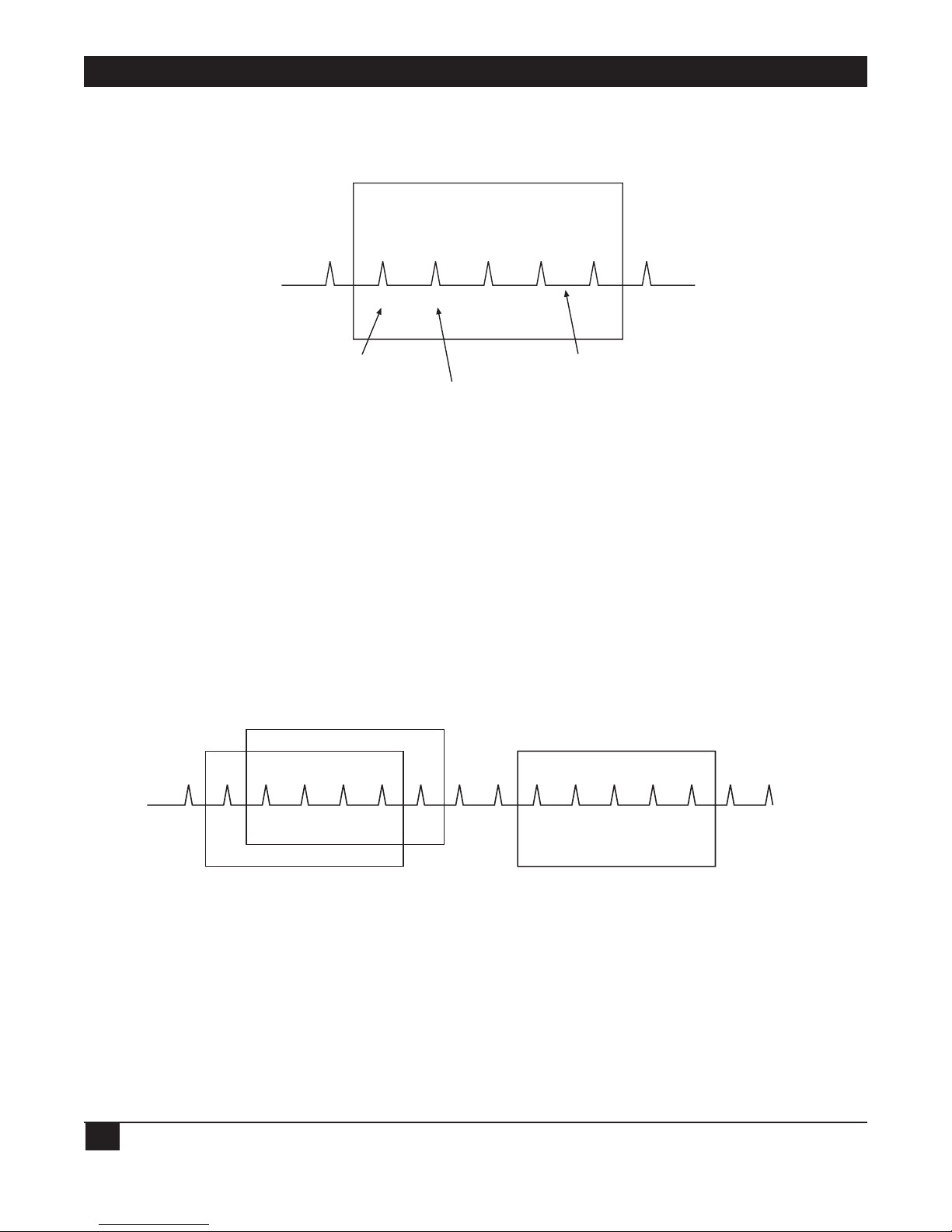
ETHERNET EXTENDERS—CONFIGURATION GUIDE
58
Figure 5-31. Monitored Events.
After the link is declared DOWN, it can only be declared UP again when the sliding monitored events window
contains only successfully monitored events.
Figure 5-32. Monitored Events—Link Down.
✓ ?
Link is UP Link is UP again
Link is DOWN
✓ ✓ ✓ ✓ ✓ ✓? ? ? ? ?
S.E.
Frame
S.E.
Frame
S.E.
Frame
S.E.
Frame
F.S.E.
Frame
S.E.
Frame
S.E.
Frame
✓ ? ✓ ??
Error Threshold = 3
Monitored Events = 5
Sliding Monitored Events Window
Monitored Events
(status enquiring frames
and full status enquiry
frame = 5)
Unacknowledged.
Frame
Acknowledged.
Frame
Link is DOWN when unacknowledged monitored events > 3
Link is UP when unacknowledged monitored events < 3
Page 62

CHAPTER 5: Advanced Setup Menu
59
FRAME RELAY DLCI PARAMETERS
The parameters in the Frame Relay DLCI Parameters menu are described below.
DLCI
Select this parameter to specify the DLCI number.
State
Select this parameter to specify whether the DLCI is Enabled or Disabled (for receive/transmit).
CIR
Select this parameter to specify the maximum amount of data in bits which the network guarantees to transfer
during the measurement interval (the measurement interval is usually one second). The value of this
parameter is obtained from the Frame Relay provider.
Excess
Select this parameter to specify the maximum amount of uncommitted data bits that the network will attempt
to deliver during the measurement interval. The value of this parameter should be received from the Frame
Relay provider.
Throughput
Select this parameter to specify the average number of data bits per second transferred by the network. When a
measurement interval of one second is assigned to the CIR, the throughput value should equal the CIR value.
Access Control (Security)
Figure 5-33. Access Control Menu Outline.
Device Control
2
Setup
1
Advanced Menu
Access Control
(security)
4
External Access
Security
1
Device Security
Identity
2
Security
Host/Guest
3
Advanced PC to LAN
Bridge Link Security
4
Script Setup
5
1. Security
Authorization
1. Name 1. Security Link
2. Minimum Accepted
PPP Security
2. Password
3. Accessible
Stations/Nets
4. User Access Profiles
1. Access Mode
2. Limited Access List
1. Unlimited Access
2. Limited Access
3. Static Stations/
Net Access
Page 63

ETHERNET EXTENDERS—CONFIGURATION GUIDE
60
To access the Access Control menu:
In the Advanced menu, press 1. The Setup menu appears.
In the Setup menu, press 4. The Access Control menu appears.
ACCESS CONTROL
(Device name — Name)
1. External access security
2. Device security identity
3. Security Host/Guest
4. Advanced PC to LAN Bridge link security
5. Script setup
ESC - Return to previous menu
Choose one of the above :
The options in the Access Control menu are described below:
E
XTERNAL ACCESS SECURITY
Select this parameter to protect your LAN against unwanted entry by outside users. Choose from the following
options:
• None—Access denied to all users.
• User Access Profile—Allow/deny access according to the User Access Profile (see below).
• RADIUS—Allow/deny access according to the RADIUS Authenticator.
• User Access Profile+RADIUS—Access is allowed if the User Access Profile allows it—OR if the User Access
Profile denies access but the RADIUS Authenticator allows it.
NOTE
If you select RADIUS, configure the RADIUS Access parameters from the Host
Parameters menu.
Minimum Accepted PPP Security
Select this option to specify the minimum security to none, PAP, or CHAP.
PPP supports 2 types of security systems:
• CHAP (Challenge Handshake Authentication Protocol)—CHAP is a type of authentication in which the
authentication agent (typically a network server) sends the client program a key to be used to encrypt the
username and password. This enables the username and password to be transmitted in an encrypted form
to protect them against hackers.
Page 64

CHAPTER 5: Advanced Setup Menu
61
• PAP (Password Authentication Protocol)—PAP is the most basic form of authentication, in which a user’s
name and password are transmitted over a network and compared to a table of name-password pairs.
Typically, the passwords stored in the table are encrypted. The main weakness of PAP is that both the
username and password are transmitted in an unencrypted form.
Accessible Stations/Nets
Select this parameter to define parameters which limit public access to the network. Access can be allowed for
all stations/nets, only certain stations/nets, or only stations/nets which are static. When the access mode is
“limited,” use the access list to define which stations/nets have access.
User Access Profiles
Select this parameter to view and modify user access profiles in the access control users list. The list contains
user names, security parameters, and dialback options.
D
EVICE SECURITY IDENTITY
Name
Select this parameter to assign a name to the Ethernet Extender for access to the ISP’s central access router.
The maximum length is 30 characters.
Password
Select this parameter to assign a password to the Ethernet Extender for access to the ISP’s central access router.
The maximum length is 30 characters.
S
ECURITY HOST/GUEST
Select this parameter to define a link’s security status. When a link is defined as a Host, users are approved
according to your profile list. When a link is defined as a Guest, the device sends its name and password to be
approved by the host. The Guest mode is the default.
A
DVANCED PC TO LAN BRIDGE LINK SECURITY
Use this parameter to configure advanced security for remote access from a PC client, when the Ethernet
Extender is configured as a bridge.
S
CRIPT SETUP
The Ethernet Extender scripting tool allows you to negotiate an initial login, required by some ISPs. The initial
login usually consists of a username, a password, and possibly some other information that has to be entered to
gain access to the ISP.
The Ethernet Extender script is a sequence of commands, with a maximum of 20 commands in the script. As
soon as a physical connection to the remote host is achieved (and the script is enabled), the Ethernet Extender
begins to forward the script. Script processing finishes when the last script command has been forwarded.
The Ethernet Extender script comprises one or more command lines. Each command line consists of a
Command Code followed by an Argument.
Page 65

ETHERNET EXTENDERS—CONFIGURATION GUIDE
62
Command Code
The command codes are described below.
waitcase pattern Waits until the specified case-sensitive pattern is received from the remote host.
Then, forwards the next command. The maximum pattern length is 24 characters.
Or, waits until timeout (default = 15 seconds). The link then disconnects and the
Ethernet Extender performs the same actions as required during authentication
failure.
waitnocase pattern As above, with no case sensitivity.
send pattern Transmits specified pattern to remote host. The pattern can contain any recognized
control symbols. The maximum pattern length is 24 characters.
sendhide pattern As above. However, the pattern is displayed on the screen as asterisks. The
control symbol is displayed as two asterisks when editing and as one when viewing.
timeout number Changes the timeout for waitcase, waitnocase, and getip commands. The number is
the timeout value, in seconds. This value can be any number from 1 to 99 and will be
used until the next timeout command.
delay number The delay in seconds between sending commands. All symbols received during this
time will be ignored. This value can be any number from 1 to 99.
getip number This command waits for an IP address from the remote host. If the ISP returns
several IP addresses in a string, the number specified by this command will
determine which IP address should be used.
If an IP address is received successfully from the host, and the Single IP feature is
enabled, the IP address will be used on the Ethernet Extender WAN interface. If an IP
address is not received successfully within the specified timeout period, the link
disconnects.
Argument
The argument is any string without apostrophes, quotation marks, or unsigned integers (depending on the
command). In addition to ASCII symbols, the argument string can include any control characters with ASCII
codes from 1 to 31. While editing scripting commands, these symbols are entered in the “control” mode: Each
symbol is entered as “^,” followed by the corresponding ASCII character from “A” to “[.” The letters must be in
upper case.
Example:
Code to wait/send Control Sequence
0x0A (line feed) ^J
0x0D (carriage return) ^M
0x0B (escape) ^[
Page 66

CHAPTER 5: Advanced Setup Menu
63
WAN Economy Menu
Figure 5-34. WAN Economy Menu Outline.
To access the WAN Economy menu:
In the Advanced menu, press 1. The Setup menu appears.
In the Setup menu, press 5. The WAN Economy menu appears.
Device Control
2
Setup
1
Advanced Menu
Filters
1
Connection
On Demand
2
IP/IPX
Spoofing
3
Fast
Retransmission
Frame Limit
4
WAN Economy
5
1. Block and
Forwarding
1. Start
Connection
1. Keep Alive
Mode
2. Link to Link
Traffic
2. Terminate
Connection
2. RIP/SAP
Spoofing Tables
Updated Timeout
3. IP/IPX
Broadcast
Control
3. Minimum Time
Between Two
Connects
3. Change Link
Spoofing Mode
4. Quick Filters
4. Minimum Time
Between Two
Disconnects
5. Advanced
Filters
5. Connect
Manually
6. Disconnect
Manually
Page 67

ETHERNET EXTENDERS—CONFIGURATION GUIDE
64
WAN ECONOMY (Device name — Name)
Use these features:
- to reduce traffic over the WAN to a minimum and increase throughput
- to keep the link up only when it is required
1. Filters
2. Connection on demand
3. Spoofing
4. Fast retransmission frame limit: 2
ESC - Return to previous menu
Choose one of the above:
The options in the WAN Economy menu are described below:
F
ILTERS
Filtering allows you to limit the amount of traffic which enters and exits the small-office LAN via the Ethernet
Extender. Filtering is used to:
• Increase security.
• Reduce traffic to the link.
The Ethernet Extender features two types of filters:
• Quick Filters.
• Advanced Filters.
Quick Filters are used to regulate IP and IPX. A Quick Filter can neutralize IP and/or IPX protocol by blocking
all traffic of that protocol. Refer to Figure 5-35.
Figure 5-35. Action of a Quick Filter.
Traffic to the Link is
blocked by Quick Filter
Traffic to the LAN is
blocked by Quick Filter
Ethernet Extender
Quick Filter
Quick Filter
LINK
Page 68

CHAPTER 5: Advanced Setup Menu
65
Advanced Filters are used to regulate traffic in both directions. (Refer to Figure 5-36).
• From LAN to the Link. Using filters here will forward or block traffic from the LAN outwards.
• From Link to the LAN. Using filters here will forward or block traffic from the link inwards.
Using a variety of parameters, Advanced Filters can be used to regulate different protocols, to totally or partially
block traffic, and to control traffic between links.
Figure 5-36. Action of an Advanced Filter.
There are two modes through which filtering can be implemented: blocking and forwarding.
Blocking
The block command causes the Ethernet Extender to test every packet of data that is sent to or from the LAN.
If the packet passes the test, passage is denied.
Example:
You want to ensure that IP/UDP packets do not go on to the link in the direction of the Internet/Intranet.
Thus, you design a filter which tests each packet to see if it is an IP/UDP packet. If the packet tests positive, it is
automatically blocked.
Forwarding
The forward command works in the same way as the block command. However, with forwarding, if the packet
passes the test, it is allowed passage to or from the LAN.
Example:
You want to allow a certain user on the small-office LAN to access the Internet for FTP purposes. To do this, you
create a filter to test each packet for the IP host address of the specified user and the FTP socket of the packet.
If the packet passes the test, it is forwarded to the Internet/Intranet.
Ethernet Extender
Link to LAN Filter
LAN to Link Filter
LAN
LINK
Traffic is regulated
Traffic is regulated
Page 69

ETHERNET EXTENDERS—CONFIGURATION GUIDE
66
Multiple Filters
Up to 18 filters can be defined. If there are 2 filters which have contradictory operations, forwarding takes
precedence over blocking.
Example:
You want to allow only one particular user on the small-office LAN to access the Internet for FTP purposes. To
ensure that no one else is able to access the Internet, create a blocking filter for all traffic going to the link. To
do this, from the Blocking and Forwarding menu enter “Block all traffic for Link1.” In addition, create a filter
to test each packet for the IP host address of the specified user and the FTP socket of the packet. Since
forwarding takes precedence over blocking, that user’s frames are forwarded.
Definition of Filter Tests
You need to define the filter test which will be applied to every packet that is transmitted. Use any combination
of the following parameters to define the filter test:
• Protocol.
• Operation (block, forward, etc.).
• Interface (LAN, Link).
• Destination and/or source IP address of the packet.
• Destination and/or source MAC address of the packet (layer 2).
• IP socket (upper and lower level).
• IP packet type (broadcast, multicast).
NOTE
Up to 18 filters can be defined. To avoid reducing Ethernet Extender performance,
minimize the number of active filters.
DEFINING FILTERS
Filters can be defined through the control port, TELNET, or SNMP. First decide on the mode and conditions
for a filter, then follow the instructions below to set filter parameters.
NOTE
Remember that forwarding takes precedence over blocking. If there is combination of
filters which contain both operations, the frame will be forwarded.
Page 70

CHAPTER 5: Advanced Setup Menu
67
QUICK FILTERS MENU
There are 4 steps in defining a Quick Filter:
1. From the Advanced Setup menu, choose Set up→WAN Economy→Filters.
2. Configure the operation.
3. Configure the broadcast control.
4. Configure the Quick Filter parameters.
FILTERS (Device name - Name)
1. Block and Forwarding
2. Link to link traffic: [FORWARD]
3. IP / IPX broadcast control - [Full Propagation]
4. Quick filters
5. Advanced filters
Esc - Return to main menu
Choose one of the above:
To configure the operation:
From the Filters menu, choose Block and Forwarding.
Toggle between Block and Forward.
To configure the broadcast control:
The broadcast control filter manages special frames which are normally propagated throughout the network.
The frames managed are:
• IP—Local broadcast propagation.
• IPX—Zero destination propagation, IPX Type 20 frames propagation.
• NETBIOS over IP—IP frames with TCP/UDP ports 137, 138, 139 propagation.
From the Filters menu, press “2” to toggle between Full Propagation and Block Propagation. The default is
Block Propagation.
To configure the link to traffic:
Use this to configure whether traffic will be sent or blocked when the Ethernet Extender is configured as a
bridge:
• Forward—forward all traffic.
• Blocked—block all traffic.
Page 71

ETHERNET EXTENDERS—CONFIGURATION GUIDE
68
To configure the Quick Filter parameters:
Quick Filters are defined per protocol. Configure each protocol that you want to block or forward.
1. From the Filters menu, choose Quick Filters.
2. To toggle between No Filters/Forward/Block, press the number of the protocol that you want to filter.
QUICK FILTERS (Device name - Name)
Choose the protocols you want to block or forward!!:
1. IP NO FILTERS
2. IPX NO FILTERS
3. SNA NO FILTERS
4. NetBIOS NO FILTERS
5. AppleTalk NO FILTERS
6. DECnet NO FILTERS
7. Others NO FILTERS
ESC - Return to previous menu
Choose one of the above: Press Enter.
A
DVANCED FILTER MENU
There are 4 steps in defining an Advanced Filter:
1. From the Advanced Setup menu, choose Set up→WAN Economy→Filters.
2. Choose Advanced Filter.
3. If you are defining a new filter, choose Add. If you are editing a filter, choose edit and enter the filter
number.
4. Define the desired parameters.
Advanced Filter Concepts
When defining an advanced filter, the following parameters must be determined:
• Filter ID—A selection number used to view, edit, or delete a particular file. To work with any filter, the Filter
ID number must be entered.
Page 72

CHAPTER 5: Advanced Setup Menu
69
ADD FILTERS (Device name - Name)
ENTER - Enter data
T - Toggle (parameters inside [] )
N - Next line (skip this one)
SPACE - Move right
BACKSPACE - Move left
ESC - Return to previous menu
Filter ID - 1
• Protocol—The protocol on which the filter operates.
• Operation—Used to define the action of the filter.
• Interface—Used to determine the filter interface.
• Source Address—Used to define the source address of passing frames.
• Destination Address—Used to define the destination address of passing frames.
• High level (IP only)—Used to include or exclude high-level protocols.
• Source/Destination Port—Used to define the port source/destination address of an application.
• Source/Destination Socket—Used to define the socket source/destination address of an application.
• Low Level—Used to include or exclude the low-level protocols.
• Mask—Used to define a mask filter.
• Status—Used to define the filter’s status.
True-False Menus
Many of the Advanced Filter parameters can be configured so that:
• Frames with that parameter pass (true); or
• Frames without that parameter pass (false).
For example, if you choose BroadCast-True, any frame which is BroadCast will pass. If you choose BroadCastFalse, any frame which is not BroadCast will pass.
Advanced Filter Parameters
• Filter ID—The system automatically assigns a new number to each filter.
• Protocol—The protocol on which the filter operates.
• Operation—The action which the filter applies to a frame that passes. They are Forward, Block, Connect,
and Disconnect.
The operations are listed in their order of priority. For example if the connect and disconnect commands are
applied to a frame, the connect command takes precedence.
Page 73

ETHERNET EXTENDERS—CONFIGURATION GUIDE
70
NOTE
Connect and disconnect are only relevant to Connection on Demand. When accessed
through the Filter menu, only they appear disabled. Refer to Connection on Demand
on page 72 for more information.
• Interface—The area where the filters will act. If you want to filter traffic going to the LAN, choose LAN. If
you want to filter traffic going to the link, choose Link.
• Source Address—Toggle to the desired address type (MAC or NET). The address format (hexadecimal or
binary) appears. Type in the complete source address.
If you want to include a group of addresses, type <x> to indicate “Don’t care.” For example, a filter with the
MAC source address the 4020.D2FE.xxxx will pass any address beginning with 4020.D2FE.
• Destination Address—Toggle to the desired address type (MAC, NET, All, BroadCast, MultiCast). The
address format (hexadecimal or binary) appears. Type in the complete destination address. Choose True or
False.
Normally, a frame has a particular destination, as specified in the destination address field of the frame.
Such frames are referred to as “All” frames. “BroadCast” frames are intended for all stations. If you specify
“BroadCast,” do not specify a mask pattern.
• High Level—When you choose this parameter, 2 choices appear: Yes and No.
When “Yes” is chosen, a list of high-level protocols appear. The high-level protocols are: FTP, WWW,
TELNET, E-MAIL, TFTP, SNMP, DNS, and RIP. Select the protocols you want to filter. Choose True or False.
• Source/Destination Sockets—This parameter differs for IP and IPX:
IP—The Destination Port is enabled when no high-level protocol is specified. If you define a port
number in decimal numbers, define the low-level protocol as UTP or TCP. If no port number is
defined, define the low-level protocol as UTP, TCP, or ICMP. Choose True or False.
IPX—If a socket address or low-level protocol is not defined, a socket number may be specified. Choose
True or False.
• Low Level (IP protocol)—Toggle to the required low-level protocol for the filter. If the port number is
defined in decimal format, specify the low-level protocol as UTP or TCP. If the no port number is defined,
specify the low-level protocol as UTP, TCP, or ICMP. Choose True or False.
• Low Level (IPX protocol)—Toggle to the required low-level protocol for the filter. If a socket is defined in
the destination address, a low-level protocol or socket number may not be specified. Conversely, if a socket
address or low-level protocol is not defined, a socket number may be specified.
Page 74

CHAPTER 5: Advanced Setup Menu
71
• Mask—A mask is a test pattern that is used to allow certain frame patterns only. You define a code against
which the frame is compared.
To create a mask, toggle to “Yes.” 3 pairs of codes and offsets must be created. The offset defines the point
in the frame at which the comparison is made. For example, an offset of 8 means that the 8th byte is
compared to the code. The offset can be from the 7th byte onwards. The frame is made of 3 different
portions:
• MAC—is at the beginning of the frame.
• LLC—is after the source address in the frame.
• DATA—is after the LLC section in the frame.
For each code-offset pair, select the code format:
• Binary—specify 48 address bits to be either 0, 1, or X (don’t care).
• Hexadecimal—specify 12 hex digits to be 0-F or X (don’t care).
For each code-offset pair, choose True or False.
Every frame, at the designated offsets, is compared to the 3 codes in the mask. If all 3 codes and the TrueFalse condition match the code written in the frame, the frame passes.
NOTE
Only 1 mask per filter can be defined.
• Status—Toggle between:
• Active.
• Not Active—Not active allows you to define filters which can be stored and used at a later time.
Saving Filter Parameters
All filters are stored in the Flash Memory, thereby preserving them if the power goes down. When filtering is
selected, all of the filters are copied into the RAM. The RAM copy is then used to activate the software-filtering
process. Any filter which is modified (by clearing all, deleting one, or changing a parameter) goes into effect
immediately. The previous filter also remains in effect until the system is rebooted.
To exit filtering and return to the main Setup menu, press Esc. The following prompt appears: ‘up’ (Y/N)?
Press Y to save changes in the Flash Memory. Press N to cancel your changes. The system loads the previous set
of masks the next time the system is rebooted.
Page 75

ETHERNET EXTENDERS—CONFIGURATION GUIDE
72
CONNECTION ON DEMAND
In order to save money, you may want to limit the time that a link is kept open. COD allows you to determine
the traffic conditions that open and close the link. Using COD, a line is opened only when traffic conditions
fulfill specified conditions. When there is no need for a connection, the line is automatically terminated.
COD is only effective if:
• The line is connected to a modem or ISDN (a dialup link).
• The link is asynchronous.
• The Connection Type is Originate or Answer&Originate.
If the Connection Type is Answer Only, the line connection is started when the unit is turned on in order to
receive calls. If the Connection Type is Originate Only or Answer&Originate, the connection will start when a
telephone number is defined.
You need to configure:
• Start Connection.
• Terminate Connection.
Start Connection
Start Connection is used to determine under which conditions is a line established. To use this function, the
line must not be designated as Answer Only. After a physical connection is made, data is transferred.
Start Connection has 4 possible options:
• Upon Power Up—The connection is established when the unit is turned on. Upon Power Up is
recommended for leased lines only.
• Any Frame to Forward—The connection is established when any frame that is directed to the link arrives.
• Specific Frame to Forward—The connection is established only when specific types of frames directed to
the link arrives. To determine which frames are establish a line, filters are used to. Specify the type of frame.
Any number of filters can be used. Filters work as an Boolean “OR”; by specifying a filter for frame type A
and filter for frame type B, you establish a line for Frame type A or Frame type B.
Choosing this option will automatically open the Advanced Filter menu, with Connect Operation selected.
• Never—The line is permanently cut off. In this case, you manually decide when to activate a line.
Page 76

CHAPTER 5: Advanced Setup Menu
73
Terminate Connection
Terminate Connection is used to determine under which conditions a link terminates. Termination takes place
only after a physical connection is made.
Terminate Connection has 4 options:
• Never—The line is never terminated. Never is usually used only when Upon Power Up is used.
• No Frame to Forward—The line is terminated after a specified time passes without a frame passing through
the line. You specify the time in which a frame must pass. 60 seconds is the default.
• Upon time out—The line is terminated after a fixed period of time regardless of the traffic. 60 seconds is
the default.
• No Specific Frame to Forward—The line is terminated if the traffic of a specific type of frame falls below a
certain rate over a period of time. You determine the number of frames and the time period in which they
must pass. Using filters, you specify which type of frames are counted. If frame other than those specified
pass through, they are not counted.
Choosing this option will automatically open the Advanced Filter menu.
COD includes 4 other options which can be used to regulate line time.
• Minimum Time Between 2 Connections—This option determines how much time there must be between a
line being terminated and then reactivated. This option is only used when Upon Power Up is chosen in
Start Connection. All other options are determined by the frame traffic.
• Minimum Time Between 2 Disconnections—This option determines the minimum time between two
disconnections. Using this option allows you to determine a minimum time-up. This option overrides other
Terminate Connection options.
• Connect Manually—This option activates a line immediately. This option overrides any other Connection
option, including Minimum Time Between 2 Connections.
• Disconnect Manually—This option terminates a line immediately. This option overrides any other
Terminate option, including Minimum Time Between 2 Disconnections.
The following examples demonstrate how COD can be used.
Page 77

ETHERNET EXTENDERS—CONFIGURATION GUIDE
74
Example 1:
A company needs their Ethernet Extender to be connected to the Internet 24 hours a day. Therefore the
following must be defined:
• Start Connection is Upon Power Up.
• Terminate Connection is Never.
Figure 5-37. Permanent Connection.
Example 2:
To lower expenses, Ethernet Extender is configured so that a line to the Internet is activated when there is a
need to connect to the Internet and terminates when no frames are transmitted for 60 seconds. Therefore the
following must be defined:
• Start Connection is Any Frame to Forward.
• Terminate Connection is No Frame to Forward for 60 seconds.
Figure 5-38. Any Frame Starts a Connection.
Connection is
never terminated
ISDN
Internet
Ethernet Extender
The connection is permanent
Connection is
terminated if 3 frames
are not forwarded in
60 seconds
Internet
ISDN
Ethernet Extender
Any frame starts a connection
Page 78

CHAPTER 5: Advanced Setup Menu
75
Example 3:
The company management wants to allow only the PC with the IP address 1.2.3.4 access to the Internet. In
addition, the connection to the Internet is to be terminated if 3 frames every 60 seconds are not transmitted
from Using the Specific Frame to Forward option ensures that only the specified PC has access this PC.
Therefore the following must be defined:
• Start Connection must be Specific Frame to Forward. A filter which allows only frames from the 1.2.3.4 IP
address must be defined.
• Terminate Connection must be No Specific Frame to Forward. A filter which counts only frames from the
1.2.3.4 IP address must be defined. In addition, the rate must be defined at 3 frames/60 seconds.
Figure 5-39. Limiting Access to a specific PC.
Example 4:
A company uses a phone line which uses a phone and modem to connect to the Internet. The only time that
the employees may connect to the Internet is if they need to upload files to or download files from a FTP site.
Any connection to the Internet is to be done manually. After the file has been uploaded or downloaded, the
connection is to be terminated automatically. Therefore the following must be defined:
• Start Connection must be Never. Any time someone wants to connect, the user must connect manually.
• Terminate Connection must be Upon Time Out. The time is set to 30 seconds.
• Set filter to FTP Only Forwarded.
Connection is terminated
if 3 frames from PC
1.2.3.4 are not forwarded
in 60 seconds
Internet
P.T.T.
Modem
PC 1.2.3.7 is blocked
from the Internet
Ethernet Extender
PC 1.2.3.6 is blocked
from the Internet
PC 1.2.3.5 is blocked
from the Internet
PC 1.2.3.4 is able to
connect to Internet
1.2.3.7
1.2.3.6
1.2.3.5
1.2.3.4
Page 79

ETHERNET EXTENDERS—CONFIGURATION GUIDE
76
Figure 5-40. Manual Connection.
IP/IPX Spoofing
Spoofing is a technique used to reduce network overhead, especially in wide-area networks (WANs). Some
network protocols send frequent packets for management purposes. These can be routing updates or keepalive messages. In a WAN, this can introduce significant overhead, due to the typically smaller bandwidth of
WAN connections.
Spoofing reduces the required bandwidth by having devices, such as bridges or routers, answer for the remote
devices. This fools (spoofs) the LAN device into thinking the remote LAN is still connected, even though it’s
not. The spoofing saves the WAN bandwidth, because no packet is ever sent out on the WAN.
IP/IPX SPOOFING
( Device name - Name)
Keep Alive
(IPX)
1. Keep Alive mode: [Disabled]
2. Timeout - PC-LAN bridge links (minutes): 120
RIP/SAP spoofing
(IP/IPX)
3. RIP/SAP spoofing tables updated timeout (minutes): 30
4. Change link spoofing mode
Link 1 spoofing mode: Disabled
Link 2 spoofing mode: Disabled
ESC - Return to previous menu
Choose one of the above:
Connection is terminated if no
frame passes within 30 seconds
Internet
Modem
Ethernet Extender
The connection is manual
Page 80

CHAPTER 5: Advanced Setup Menu
77
The parameters in the Spoofing menu are described below:
Keep Alive (IPX)
Keep Alive Mode
Select this parameter to enable or disable the Keep Alive mode. Keep Alive mode allows the remote user to
remain on the local server station list for a specified period of time during link disconnection.
Timeout
The amount of time inactive PC to LAN links are kept open when the Ethernet Extender is configured as a
bridge.
NOTE
SPx spoofing is not supported.
RIP / SAP Spoofing (IP/IPX)
Spoofing is a technique used to reduce network overhead, especially in a WAN. Some network protocols send
frequent packets for management purposes. These can be routing updates or keep-alive messages. In a WAN,
this can introduce significant overhead, due to the typically smaller bandwidth of WAN connections.
Select this parameter to determine the length of time (in minutes) between exchange of RIP and IPX SAP
tables over the WAN. This parameter is applicable unless spoofing mode is set to “Upon Change” only.
Change Link Spoofing Mode
This parameter can have the following values:
• Disabled (default). When disabled, RIP/SAP updates are sent:
• After a defined time (default time is 30 seconds IP, 60 seconds IPX RIP and SAP);
• AND when there is a change in the network topology; for example an interface goes up or down, or a
routing entry is aged.
• Enabled. When enabled, RIP/SAP updates are sent:
• After a defined time.
• When there is a change in the network topology.
• After a defined time and a change in network topology.
• Enabled COD. When this parameter is set to Enabled COD, updates are sent according the:
• Disabled parameter when the line is up.
• Enabled parameter when the line down.
Page 81

ETHERNET EXTENDERS—CONFIGURATION GUIDE
78
FAST TRANSMISSION FRAME LIMIT
This option allows you to insert the maximum number of acknowledge frames in the buffer to prevent
unnecessary retransmissions on the WAN.
F
ACTORY DEFAULT
The Factory Default menu allows you to change all configuration parameters back to their factory defaults.
To access the Factory Default menu:
1. In the Advanced Setup menu, press 1. The Setup menu appears.
2. From the Setup menu, press 6. A string of text appears, prompting you to reset certain parameters.
3. Press Y to reset the parameters to the factory default, or N to avoid reset. The next string of text appears.
The screen below displays all the parameters that can be reset.
Reset MONITOR parameters to factory default ? (Y/N): N
Reset DEVICE ID parameters to factory default ? (Y/N): N
Reset MASKS parameters to factory default ? (Y/N): N
Reset FORWARDING parameters to factory default ? (Y/N): N
Reset SPOOFING parameters to factory default ? (Y/N): N
Reset SNMP parameters to factory default ? (Y/N): N
Reset LINKS parameters to factory default ? (Y/N): N
Reset DOWNLOAD parameters to factory default ? (Y/N): N
Reset COD parameters to factory default ? (Y/N): N
Reset MODEMS parameters to factory default ? (Y/N): N
Reset ISDN parameters to factory default ? (Y/N): N
Reset FRAME RELAY parameters to factory default ? (Y/N): N
Reset PPP parameters to factory default ? (Y/N): N
Reset HOST IP parameters to factory default ? (Y/N): N
Reset TELNET parameters to factory default ? (Y/N): N
Reset RADIUS parameters to factory default ? (Y/N): N
Reset SECURITY parameters to factory default ? (Y/N):
Page 82

CHAPTER 5: Advanced Setup Menu
79
5.2 Device Control Menu
Figure 5-41. Device Control Menu.
To access the Device Control menu:
In the Advanced menu, press 3. The Device Control menu appears.
DEVICE CONTROL ( Device name - Name)
1. Software download
2. Upload device parameters to TFTP server
3. Download device parameters from TFTP server
4. Reset options
5. Control other device (bridge link only)
6. Terminal type
ESC - Return to previous menu
Choose one of the above :
The options in the Device Control menu are described on the next page.
Device Control
2
Setup
1
Advanced Menu
Software
Download
1
Upload
Device
Parameters
to TFTP Server
2
Download
Device
Parameters from
TFTP Server
3
Reset
Options
4
Control
Other Device
5
Terminal
Type
6
1.Download from
TFTP Server
1. Reset Device
1. VT-100,
UT-200, VT-220
ANSI Terminals
2. XMODEM via
Control Port
(Boot Manager)
2. Reset Link
2. VT-52, IBM
3101 Terminals
3. Download
Software to
ISDN Module
3. Reset
Interface Module
3. Other
Terminals
Page 83

ETHERNET EXTENDERS—CONFIGURATION GUIDE
80
Software Download
SOFTWARE PARAMETERS IN THE DOWNLOAD
(Device name - Name)
1. The parameters in the download from TFTP Server
2. The parameters in the XMODEM via control port (BOOT Manager)
3. The parameters in the download software to ISDN module
ESC - Return to previous menu
Choose one of the above :
Select this option to download a new software version.
The Ethernet Extender includes a Dual Image Flash, capable of storing two different versions of software in two
different partitions.
Upon reset (or boot; refer to Appendix B), the Ethernet Extender automatically runs the program stored in the
primary (active) partition.
New software versions are loaded into the secondary (backup) partition. If loading succeeds, the backup
partition becomes primary active and reset is automatically performed, running the new software version. If
loading fails, however, the device will be still capable of working, since the flash partition storing the old version
is still primary. Refer to Figure 5-42.
Figure 5-42. Using the Dual Image Flash.
Dual Image Flash can be controlled by the BOOT Manager. You use the BOOT Manager to manually define
active and backup partition, run backup partition, erase some or all information from Flash, etc. The BOOT
Manager is accessible via the above menu or immediately after resetting the hardware. Refer to Appendix B for
a detailed description of the BOOT Manager.
Original
S/W Version
Copy 1
Original
S/W Version
Copy 2
Original
S/W Version
New
S/W Version
Original
S/W Version
New
S/W Version
Primary Partition Secondary Partition
Step 1
Primary Partition Secondary Partition
Step 2
Primary PartitionSecondary Partition
Step 3
Page 84
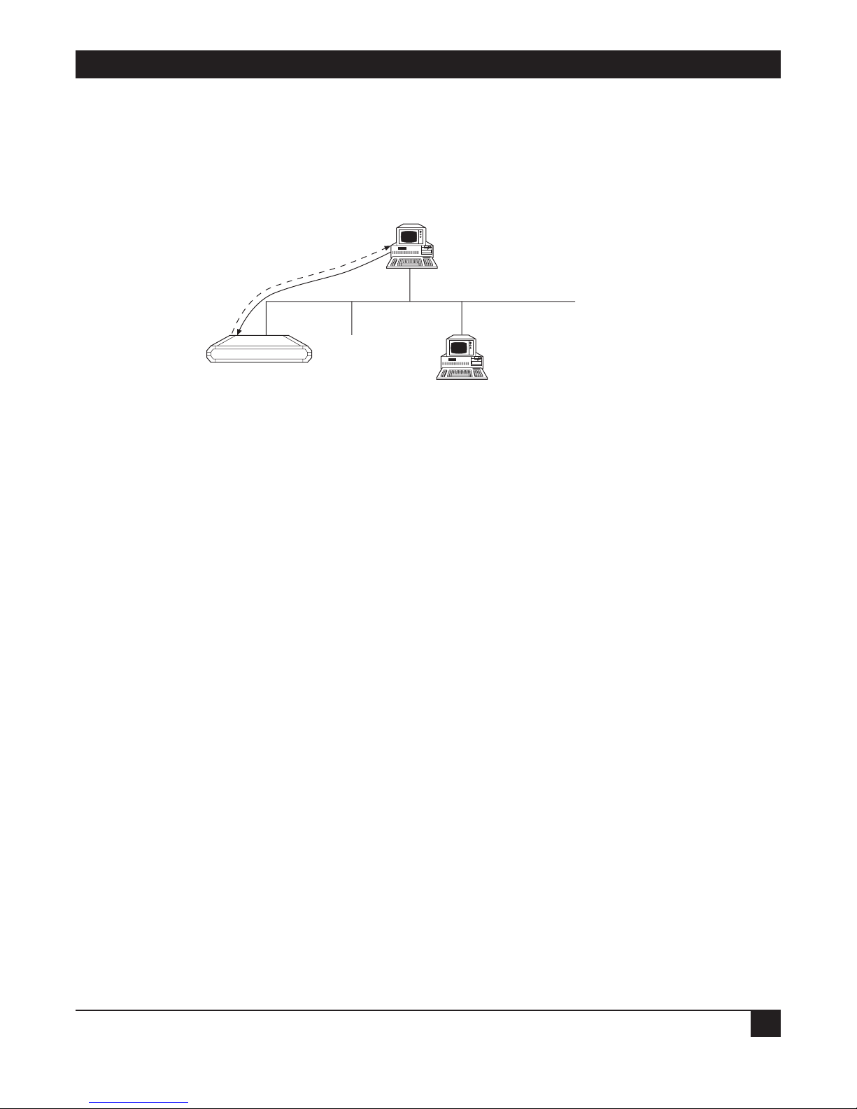
CHAPTER 5: Advanced Setup Menu
81
The options in the Software Download menu are described below:
D
OWNLOAD FROM TFTP SERVER
TFTP is a IP/UDP client-server application. The unit is a TFTP client. Operating opposite the client, you need
a TFTP server connected to the LAN or WAN interface via an IP network.
Figure 5-43. Downloading from a TFTP Server.
To download a new software version via TFTP server:
1. Select option 1 from the Software Download menu.
Do you want to download new software version? (y/n): Y
TFTP server IP address: 194.90.182.34
New software file name: webebraseb.mbi
Download process will erase the program code
in the second partition of the device.
Upon completion of the download,
the device will be reset automatically.
Press ‘S’ to start the download process
or
ESC to return to previous menu:
2. Confirm that the Do You Want To Download New Software Version? field is set to Yes.
3. In the TFTP Server IP Address field, type the IP address of the TFTP server.
4. In the New Software File Name field, type the path and file name of the new software version.
NOTE
The IP address and the new software version file name can also be defined through
the Setup menu.
5. Press S to start the download process.
Ethernet Extender
File Transfer
TFTP Server
IP Address: 192.168.10.11
Holds file at C:\booting\boot.exe
Page 85

ETHERNET EXTENDERS—CONFIGURATION GUIDE
82
During the process, the new program code is downloaded to the FLASH backup partition, thus erasing its
previous contents.
Upon completion, the newly downloaded FLASH partition becomes active, while the old version’s partition
becomes backup. The device automatically resets, running the new program stored in the active partition.
During the download process, a counter shows the number of packets that have passed. Downloading can
be interrupted at any time by pressing the ESC key.
XMODEM
VIA CONTROL PORT (BOOT MANAGER)
You use this option to access the BOOT Manager via the control port.
The BOOT Manager is discussed in Appendix B.
D
OWNLOAD SOFTWARE TO ISDN MODULE
The ISDN program is stored in a dedicated Flash Memory.
Downloading a new ISDN version is performed using an XMODEM protocol, via the control port only.
To download a new ISDN version:
1. Select option 3 from the Software Download menu.
Page 86

CHAPTER 5: Advanced Setup Menu
83
DOWNLOAD TO ISDN MODULE (Device name - Name)
1. ISDN Module 2
2. ISDN Module 3
3. ISDN Module 4
Choose one of the above: 1
You have chosen ISDN Module 2.
The device will be STOPPED now,
the existing ISDN software will be ERASED,
and you will be able to download new software
to the ISDN module using XMODEM protocol.
Press ‘P’ to proceed or ESC to return to previous menu:
Do you want to change your terminal data rate? (Y/N): Y
1. 19200
2. 38400
3. 57600
4. 115200
Choose one of the above: 4
Change your terminal data rate to 115200 bps and press ENTER
Contacting ISDN module....done
Erasing ISDN software.........done
Contacting ISDN module............done
Erasing FLASH........done
You may start now the XMODEM process....
( —Here you start XMODEM file transfer at your terminal emulator— )
Done.
Change your terminal data rate to 9600 bps and press ENTER.
2. Choose ISDN Module.
3. Press P to proceed.
4. To change the baud rate, press Y. Choose the appropriate rate.
5. Change the terminal baud rate to the rate chosen in Step 4. Press ENTER. The ISDN software is erased.
6. Via XMODEM, download the ISDN software. At the end of the XMODEM process, the unit resets itself and
starts working with the new software version.
Page 87

ETHERNET EXTENDERS—CONFIGURATION GUIDE
84
Device Configuration Parameters Upload/Download
This option allows you to save the device configuration in a file or load a saved configuration to the device,
using the TFTP protocol. TFTP is an UDP/IP client-server application. The unit is a client TFTP. Operating
opposite the client, you need to connect a TFTP server to the LAN or WAN interface via an IP network.
Upload Device Parameters to TFTP Server
Select this parameter to save device configuration parameters into a file by uploading to the TFTP server. This
operation sends all unit parameters to the TFTP server and will be saved under a filename that you specify.
Figure 5-44. Downloading/Uploading Parameters.
To upload device parameters:
1. Activate the TFTP server application connected to the unit via an IP network.
2. Configure the following IP parameters: IP address, IP mask, and IP default gateway.
3. Select the TFTP upload option.
4. Enter the TFTP server IP address.
5. Assign a name to the configuration file you want to save on the server (for example, web_isdn.cfg).
6. Press S to start the upload process.
D
OWNLOAD DEVICE PARAMETERS FROM TFTP SERVER
Select this option to load device configuration parameters from a file by downloading from the TFTP server.
To download device parameters:
1. Activate the TFTP server application connected to the unit via an IP network.
2. Configure the following IP parameters: IP address, IP mask, and IP default gateway.
3. Select the TFTP download option.
4. Enter the TFTP server IP address.
5. Enter the name of the configuration file you want to download from the server (for example,
web_isdn.cfg).
6. Press S to start the download process.
TFTP server
Parameter file download/upload
IP
Ethernet Extender
Page 88

CHAPTER 5: Advanced Setup Menu
85
NOTE
Upon completion of the download process, the unit performs reset. The new
parameters only come into effect after resetting.
Reset Options
Select this option to reset the device, link, or interface module. The interface module reset relates to ISDN
options only.
Control Other Device
This option is only applicable when the Ethernet Extender is configured as a bridge. Select this option to
configure the Ethernet Extender on the other side of the bridge link.
Terminal Type
Select this option to choose a terminal type. Since each terminal type uses different ASCII control codes for
cursor control, the Ethernet Extender requires this information to clearly display the screens clearly.
5.3 List of Operations
This section contains a quick-reference table of operations, divided into sections according to the Advanced
menu. For your convenience, the keystrokes to carry out these operations are included, starting from the
Advanced menu. Browse through the list to find the action you want to perform and simply type the figures in
the order in which they appear. This brings you to the required screen. Follow the on-screen instructions to
complete the action.
To… You Press…
Host Parameters
Change the device name 1.1.1.1
Enter name of contact person 1.1.1.2
Enter the location of the device 1.1.1.3
Set local administered address 1.1.1.4.1
Set active address to local or burned-in 1.1.1.4.2
Enter IP address 1.1.2.1
Enter IP mask 1.1.2.2
Enter default gateway 1.1.2.3
Enter IP host interface 1.1.2.4
Set read community 1.1.3.1
Set write community 1.1.3.2
Set trap community 1.1.3.3
Add parameters to manager table 1.1.3.4.a
Clear parameters in manager table 1.1.3.4.c
Delete specific parameters in manager table 1.1.3.4.d
Enter file server IP address 1.1.4.1
Enter file name to be transferred 1.1.4.2
Set retransmitting timeout 1.1.4.3
Set total timeout 1.1.4.4
To enable/disable TELNET access 1.1.5.1
To enter a TELNET username 1.1.5.2
To enter a TELNET password 1.1.5.3
Page 89

ETHERNET EXTENDERS—CONFIGURATION GUIDE
86
To… You Press…
Routing
Change link protocol to SLIP 1.2.1.1.1
Change link protocol to CSLIP 1.2.1.1.2
Change link protocol to PPP 1.2.1.1.3
Change link cost/metric 1.2.1.3
Set header and control field compression 1.2.1.4.1
Set protocol field compression 1.2.1.4.2
Set IP compression 1.2.1.4.3
Enable/disable Multilink 1.2.1.4.4
Add static station and net 1.2.2.a
Clear all static stations and nets 1.2.2.c
Delete static station and net 1.2.2.d
Enter shared IP net 1.2.3.1
Enable/disable remote workstation IP address 1.2.3.2
Add remote workstation to IP address pool 1.2.3.3.a
Delete remote workstation from IP address pool 1.2.3.3.d
Clear all IP addresses from IP address pool 1.2.3.3.c
Enter primary domain name server 1.2.3.4
Enter secondary domain name server 1.2.3.5
Enter aging time for stations on the network 1.2.5
Interface Parameters
Enable/disable link status 1.3.1.1
Set link type to asynchronous 1.3.1.2.1
Set link type to synchronous 1.3.1.2.2
Set link type to ISDN 1.3.1.2.3
Set link type to leased ISDN 1.3.1.2.4
Set link type to frame relay 1.3.1.2.5
Set link connection type 1.3.1.3
Set link connection timeout 1.3.1.4
Set control signals mode 1.3.1.5
Set baud rate 1.3.1.6
Set parity to on or off 1.3.1.7
Set number of stop bits 1.3.1.8
Set modem settings 1.3.1.9
Set ISDN protocol 1.3.2.1
Set Frame Relay DLCI parameters 1.3.3
Access Control (Security)
Enable/disable external access security 1.4.1.1
Set minimum accepted PPP security 1.4.1.2
Set access mode to unlimited access 1.4.1.3.1.1
Set access mode to limited access 1.4.1.3.1.2
Set access mode to static stations/nets only 1.4.1.3.1.3
Edit access list 1.4.1.3.2
View user access profiles 1.4.1.4
Enter external device name for security identification 1.4.2.1
Enter external device password for security identification 1.4.2.2
Page 90

CHAPTER 5: Advanced Setup Menu
87
To… You Press…
Define a link as a host or guest 1.4.3.1
Work with scripting tool 1.4.4
WAN Economy
Block/forward filters 1.5.1.1
IP broadcast control 1.5.1.2
Quick filters—IP 1.5.1.3.1
Advanced filters 1.5.1.4
Set connection start condition to always 1.5.2.1.1
Set connection start condition to never 1.5.2.1.2
Set connection start condition to conditional 1.5.2.1.3
Set connection terminate condition to never 1.5.2.2.1
Set connection terminate condition to timeout 1.5.2.2.2
Set connection terminate condition to conditional 1.5.2.2.3
Set minimum time between two connects 1.5.2.3
Set minimum time between two disconnects 1.5.2.4
Connect link manually 1.5.2.5
Disconnect link manually 1.5.2.6
Update timeout for RIP/SAP spoofing tables 1.5.3.1
Change link spoofing mode 1.5.3.2
Enter new fast retransmission frame limit 1.5.4
Factory-Default Options
Reset monitor parameters to factory-default settings 1.6
Reset device parameters to default settings 1.6
Reset masks parameters to default settings 1.6
Reset forwarding parameters to default settings 1.6
Reset spoofing parameters to default settings 1.6
Reset SNMP parameters to default settings 1.6
Reset links parameters to default settings 1.6
Reset download parameters to default settings 1.6
Reset COD parameters to default settings 1.6
Reset modem parameters to default settings, 1.6
Reset ISDN parameters to default settings 1.6
Reset Frame Relay parameters to default settings 1.6
Reset PPP parameters to default settings 1.6
Reset host IP parameters to default settings 1.6
Reset security parameters to default settings 1.6
VIEWING PARAMETERS
View advanced configuration parameters 2.1.Link number
View interface connections status 2.2
View IP routing tables 2.3.1.
View ARP routing tables 2.3.2
View LAN statistics 2.4
Clear LAN statistics 2.4.c
Update average LAN statistics 2.4.u
View Frame Relay DLCI settings 2.5
Page 91

ETHERNET EXTENDERS—CONFIGURATION GUIDE
88
To… You Press…
DEVICE CONTROL
Download new software 3.1
Upload device parameters to TFTP server 3.2
Download device parameters from TFTP server 3.3
Reset device 3.3.1
Reset link 3.3.2
Reset interface module 3.3.3
Set terminal type to VT-100, UT-200, VT-220, ANSI terminals 3.4.1
Set terminal type to VT-52, IBM 3101 terminals 3.4.2
Set terminal type to other terminals 3.4.3
Page 92

APPENDIX A: Important ISDN Issues
89
Appendix A: Important ISDN
Issues (For U.S. Users Only)
A.1 Which ISDN Service Should You Order?
Your telephone company can offer one or more of the following ISDN switch protocols:
• National ISDN-1 (NI-1)
• AT&T Multipoint (5ESS)
• AT&T Point-to-Point (5ESS with no SPIDs)
• Northern Telecom DMS-100 Custom (DMS-100)
The Ethernet Extender operates with all of the above ISDN services. However, National ISDN-1 is
recommended, as it is common to the three North American switches:
• AT&T (5ESS)
• Northern Telecom (DMS-100) and
• Siemens (EWSD)
A.2 Ordering ISDN
To order your ISDN line:
1. Request the type of ISDN service available from the telephone company’s ISDN Ordering Center.
2. Provide the required provisioning information to the telephone company.
3. When the telephone company installs your ISDN line, obtain the following information:
• ISDN switch protocol.
• ISDN telephone numbers (two telephone numbers are highly recommended)
• ISDN Service Profile Identifier (SPID) numbers (preferably 2 SPIDs)
NOTE
Verify the SPIDs and the telephone numbers with the telephone company. An incorrect
telephone number or SPID number could prevent you from accessing your ISDN line.
Page 93

ETHERNET EXTENDERS—CONFIGURATION GUIDE
90
A.3 Provisioning ISDN
The Ethernet Extender passed the interoperability and ISDN Ordering Codes (IOC) tests at Bellcore with all
three North American switches (AT&T, Northern Telecom, and Siemens). The IOC program is designed to
simplify ordering an ISDN line for National ISDN. The Ethernet Extender is registered at Bellcore under
packages R and EZ1.
When ordering your ISDN line:
• If your ISDN switch protocol is National ISDN-1 (NI-1), request the local exchange carrier for packages R or
EZ1. Your line will be configured according to the recommended provisioning for the Ethernet Extender.
• If your ISDN switch protocol is AT&T Multipoint (5ESS/MP) or Northern Telecom DMS-100 Custom,
request the local exchange carrier for a line with:
• Data only,
• 2 SPIDs, and
• 2 phone numbers.
• If your ISDN switch protocol is AT&T Point-to-Point (5ESS/PTP), request the local exchange carrier for a
line with data only. In this case, no SPIDs are used and you will receive only one telephone number that will
be used for both B channels.
A.4 ISDN Parameters
Protocol:
• Channel A—Service provider ID (SPID).
• Channel A—Local phone (directory) number.
• Channel B—Service provider ID (SPID).
• Channel B—Local phone (directory) number.
The SPIDs and the telephone numbers assigned to an ISDN line are not tied to a particular B channel. Both
telephone numbers can access both or either of the B channels.
If your ISDN switch protocol is National ISDN-1 (NI-1), AT&T Multipoint (5ESS/MP), or Northern Telecom
DMS-100 Custom:
1. Choose the correct protocol.
2. Enter the service provider ID (SPID) and the local phone (directory) number for both channels, as
provided by the local exchange carrier.
If your ISDN switch protocol is AT&T Point-to-Point (5ESS/PTP):
Set the Protocol to 5ESS. The service provider ID (SPID) and the local phone (directory) number setting
are not required.
Page 94

APPENDIX A: Important ISDN Issues
91
An inconsistency exists between the ISDN protocols used on different types of switches. National ISDN-1
standard does not allow access to both B channels with only one SPID. If you use National ISDN-1 or AT&T
Multipoint protocols on a 5ESS switch, it is possible that you will receive only 1 SPID for both B channels. The
Ethernet Extender also supports this configuration.
If this is the case, set the service provider ID (SPID) and the local phone (directory) number of channel A. It is
not necessary to set Channel B. This allows access to both B channels using the same phone number.
Page 95

ETHERNET EXTENDERS—CONFIGURATION GUIDE
92
Appendix B: BOOT Manager
B.1 Preface
The Ethernet Extender includes a Dual Image Flash, capable of storing two different versions of software in two
different partitions.
Upon reset, the Ethernet Extender automatically runs the program stored in the primary (active) partition.
New software versions are loaded into the secondary (backup) partition. If loading succeeds, the secondary
partition becomes the primary partition and the Ethernet Extender is reset automatically, running the new
software version. If loading fails, the device is still capable of working, since the FLASH partition storing the old
version remains active.
Dual Image Flash can be controlled by the BOOT Manager. You use the BOOT Manager to:
• Download new software.
• Manually define the primary and secondary partitions.
• Run the secondary partition.
• Erase some or all information from Flash.
B.2 Accessing BOOT Manager
There are two ways to access BOOT Manager:
• Via option 2 in the Software Download menu.
• Via the “Rescue” option.
B.2.1 A
CCESS VIA SOFTWARE DOWNLOAD MENU
1. In the Advanced menu, press 3. The Device Control menu appears.
DEVICE CONTROL ( Device name - Name )
1. Software download
2. Upload device parameters to TFTP server
3. Download device parameters from TFTP server
4. Reset options
5. Terminal type
Page 96

APPENDIX B: BOOT Manager
93
2. Press 1. The Software Download menu appears.
SOFTWARE DOWNLOAD (Device name - Name)
1. Download from TFTP Server
2. XMODEM via control port (BOOT Manager)
3. Download software to ISDN module
3. Press 2 to display the BOOT Manager menu.
B.2.2 R
ESCUE
If the Ethernet Extender does not respond properly, try the Rescue option:
1. Connect to the terminal emulator.
2. Switch on the Ethernet Extender and immediately press R. The BOOT Manager menu appears.
B.3 The BOOT Manager Menu
BOOT 302 Version 1.01 (Mar 18 1997)
First : 1997 Apr 30 12:32 MBEBOOT.X 7.0A5 test1
Second: 1997 May 01 14:46 RE70A6.X Testing ISDN download in RAS (LK)
1) Load new software
2) Partitions status
3) Run second partition
4) Reactivate second partition
5) Duplicate first partition
6) Erase configuration
7) Erase all FLASH
8) Set baud rate
0) Exit
Choose one of the above:
The options in the BOOT Manager menu are described on the following pages.
Page 97

ETHERNET EXTENDERS—CONFIGURATION GUIDE
94
B.3.1 LOAD NEW SOFTWARE
Select this option to download new software via the control port using the XMODEM protocol. During the
process, the new program code is downloaded to the FLASH secondary partition, thus erasing its previous
contents.
Upon completion, the newly downloaded FLASH partition becomes the primary partition, while the old
version’s partition becomes the secondary partition. The device automatically resets, running the new program
stored in the primary partition.
Figure B-1. Dual Image Flash.
NOTE
The terminal emulator in Windows 95—HyperTerminal—has a bug: After changing
baud rate the status line presents the new value, but this value will not come into
effect unless you perform the disconnect and connect commands immediately after
the change.
B.3.2 PARTITIONS STATUS
Select this option to display information about the status of the active (first) and the backup (second) FLASH
partitions. Note that the BOOT Manager menu also displays a partial status at its upper part:
First : 1997 Apr 30 12:32 MBEBOOT.X 7.0A5 test1
Second: 1997 May 01 14:46 RE70A6.X Testing ISDN download in RAS (LK)
B.3.3 R
UN SECOND PARTITION
Select this option to run the program stored in the secondary partition of the FLASH memory. Normally that
program is the previous software version.
The “backup” program runs once. The next hardware reset or Boot will run the program stored in the primary
partition.
Original
S/W Version
Copy 1
Original
S/W Version
Copy 2
Original
S/W Version
New
S/W Version
Original
S/W Version
New
S/W Version
Primary Partition Secondary Partition
Step 1
Primary Partition Secondary Partition
Step 2
Primary PartitionSecondary Partition
Step 3
Page 98

APPENDIX B: BOOT Manager
95
B.3.4 REACTIVATE SECOND PARTITION
Select this option to turn the secondary partition into the primary partition (and vice versa). In this way you can
return to the previous software version permanently.
This command may be executed up to 16 times, after which downloading of the new software will be required.
Therefore avoid using this option for a one-time run of the old version (use the Run Second Partition option
for that purpose).
B.3.5 D
UPLICATE FIRST PARTITION
Select this option to duplicate the program stored in the active (first) partition into the backup (second)
partition.
B.3.6 E
RASE CONFIGURATION
Select this option to erase the device configuration parameters which are also stored in the flash memory.
Sometimes it is needed after downloading a new version, if its parameter set is not fully compatible with the
previous version parameters. You may also use this command to set the device to the default settings. The Erase
Configuration command is also useful if you forget the password.
B.3.7 E
RASE ALL FLASH
Select this option to erase the device configuration parameters, and the programs stored in both partitions.
Remember to download a new software before attempting to operate the device.
B.3.8 S
ET BAUD RATE
Select this option to set the device’s baud rate to 9600, 19,200, 38,400, 57,600, or 115,200 bps. For software code
download, use the highest rate possible—that is, 115,200 bps. (The baud rate must be higher than 9600 bps to
enable downloading.)
Figure B-2. Setting the Baud Rate.
XModem
Download Code
(115.2 ) kbps
Control Port
Ethernet Extender
Page 99

ETHERNET EXTENDERS—CONFIGURATION GUIDE
96
Change your terminal baud rate and press Enter 2 or 3 times to ensure that the device identifies the new value.
NOTE
The terminal emulator of Windows 95—HyperTerminal—has a bug: After changing
baud rate the status line presents the new value, but this value will not come into
effect unless you perform the disconnect and connect commands immediately after
performing the change.
B.3.9 EXIT
Select this option to exit from the BOOT Manager menu and perform BOOT/RESET Ethernet Extender.
If the BOOT Manager is idle for more the two minutes, exit will be performed automatically.
 Loading...