

Page 1
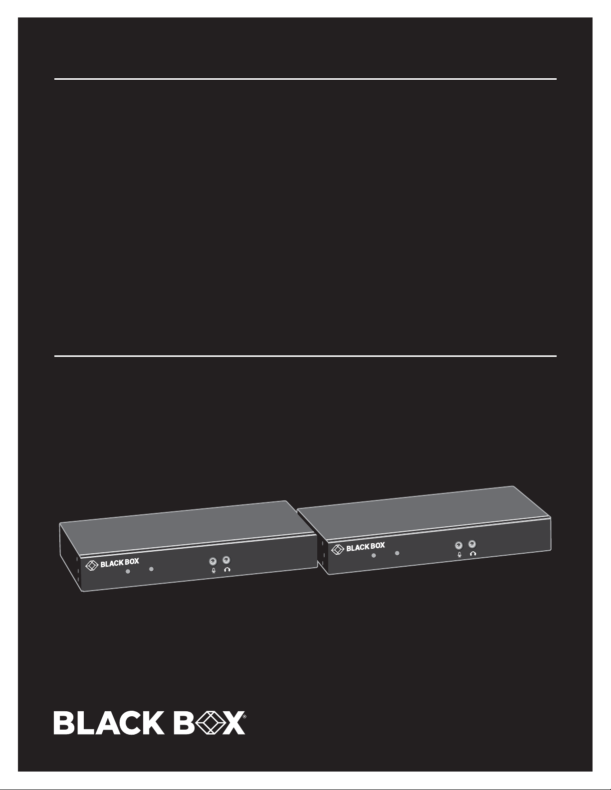
QUICK INSTALL GUIDE AND USER MANUAL
KVXLCDP-100, KVXLCDPF-100, KVXLCDP-200, KVXLCDPF-200
KVX SERIES
4K DP KVM
EXTENDER
24/7 TECHNICAL SUPPORT AT 1.877.877.2269 OR VISIT BLACKBOX.COM
DP KVM Extender Transmitter
LINK
PWR
LINK
PWR
DP KVM Extender Receiver
Page 2

NEED HELP?
LEAV E TH E TEC H TO US
LIVE 24/7
TABLE OF CONTENTS
TECHNICAL
SUPPORT
1. 8 7 7. 8 7 7. 2 2 69
QUICK INSTALLATION GUIDE .......................................................................................................................................................... 3
1. SPECIFICATIONS ........................................................................................................................................................................... 4
2. OVERVIE W ...................................................................................................................................................................................... 6
2.1 Introduction ...............................................................................................................................................................................................6
2.2 Features .................................................................................................................................................................................................... 6
2.3 What’s Included ........................................................................................................................................................................................6
2.4 Hardware Description ..............................................................................................................................................................................7
2.4.1 Transmitter ..........................................................................................................................................................................................................7
2.4.2 Receiver..............................................................................................................................................................................................................10
3. CONNECTION DIAGRAM ............................................................................................................................................................ 13
4. I N S TALL ATION ............................................................................................................................................................................ 14
APPENDIX A. REGULATORY INFORMATION ................................................................................................................................ 15
A.1 FCC Statement ....................................................................................................................................................................................... 15
A.2 NOM Statement ..................................................................................................................................................................................... 16
APPENDIX B. DISCLAIMER/TRADEMARKS ................................................................................................................................. 17
B.1 Disclaimer ............................................................................................................................................................................................... 17
B.2 Trademarks ............................................................................................................................................................................................. 17
2
1. 8 7 7. 8 7 7. 2 2 6 9 BLACK BOX .COM
Page 3
NEED HELP?
LEAV E TH E TEC H TO US
LIVE 24/7
QUICK INSTALLATION GUIDE
Follow these steps to install the extender:
1. If you have the fiber models, install the SFPs in the transmitter and receiver. Compatible SFPs from Black Box are listed in the table
below.
COMPATIBLE SFP MODULES
PART NUMBER DESCRIPTION DISTANCE
1-GBPS CONNECTIONS
LFP441 SFP 1.25-Gb, 850 -nm Multimode Fiber, LC 550 m
LFP442 SFP 1.25- Gb, 1310-nm Single-mode Fiber, LC 20 km
LFP412 SFP with Extended Diagnostics - 1250 -Mbps Multimode Fiber, 1310-nm 2 km
LFP413 SFP with Extended Diagnostics - 1250 -Mbps Single-Mode Fiber, 1310-nm 10 km
LFP414 SFP with Extended Diagnostics - 1250 -Mbps, Singlemode Fiber, 1310-nm 30 km
LFP416 SFP 1250 -Mbps, Extended Diagnostics, 10/100/1000BASE-T, SGMII Interface, RJ-45 100 m
NOTE: Other SFPs may work but have not been validated by Black Box, we recommend you use the suggested SFPs to avoid technical
incompatibilities. SFP is not included in the package, must be ordered separately.
2. Connect one end of a DisplayPort cable to the DisplayPort port on the source device (e.g. computer, server, or other IT device).
Then connect the other end to the DP IN port located on the TX unit.
3. Connect the DisplayPort display to the DP OUT port on the TX unit.
4. Connect the DisplayPort display to the DP OUT port on the RX unit.
5. Connect the USB ports of the source device and the TX unit with a USB type A-B cable. Then plug a USB keyboard, mouse, or other
USB devices into the USB ports of the RX unit.
6. Connect the RS-232 ports of the source device and the TX unit. Then connect the RS-232 ports of the RS-232 device on the RX unit
side and the RX unit.
7. Connect the microphone/speaker ports of the source device and the TX unit with the audio microphone/speaker combo cable.
Then, plug the microphone and speaker into the microphone and speaker ports of the RX unit.
8. For the CATx model, use a CAT5e cable to connect the CATx link ports on the TX unit and the RX unit.
9. For the fiber model, use two SFP modules and an optical fiber cable to connect the fiber link ports on the TX unit and the RX unit.
10. Plug the power adapter cable into the DC jacks on the TX and RX units.
NOTES:
a. We recommend using the highest quality materials (cables, SFP, etc.) to ensure optimal transmission quality.
b. If the screen does not display when you connect the computer:
1. Make sure the device cables are correctly and firmly attached.
2. Set your display device’s (TV, monitor, etc.) input source as DisplayPort.
3. Check the PC BIOS configuration of the video output setting.
4. Connect your video source to the Display DIRECTLY to check if the video signal gets through.
TECHNICAL
SUPPORT
1. 8 7 7. 8 7 7. 2 2 69
NOTES:
1. Both the DisplayPort displays respectively connecting to TX and RX units MUST support the same maximum video resolution.
2. SFP module’s bandwidth requirement is 1 Gbps minimum.
3. When plugging into any microphone or speaker ports of TX or RX units, digital DisplayPort audio extension will be disabled and
only analog audio LINE-IN/LINE-OUT extension is enabled.
1. 8 7 7. 8 7 7. 2 2 6 9 BLACK BOX .COM
3
Page 4

CHAPTER 1: SPECIFICATIONS
TABLE 1-1. TRANSMITTER SPECIFICATIONS
Console Connection
Video Output N/A
Serial Control Port (1) DB9 female
Host Connection
Video Input
Local Out Video Connection
Local Out
Link Port
RJ-45 (KVXLCDP-100, KV XLCDP-200 transmitter) CATx cable – max. length: 330 feet (100 meters)
SFP (KVXLCDPF-100, KVXLCDPF-200 transmitter)
USB Interface
Host (1) USB Type B female
Device N/A
Audio
2-way analog audio (1) Line In, (1) Line Out
Serial
RS-232 Extension Port (1) DB9 female
General
LED indicator
DDC Supported DDC, DDC2, DDC2B
Max. Video Resolution 4K @ 30 Hz, 3840 x 2160 @ 30 Hz (8-, 10-bit input)
OS Compatibility OS Independent
Housing material Chassis Metal
Operating Temperature 32 to 122° F (0 to 50° C)
Storage Temperature -4 to +140° F (-20 to +60° C)
Relative Humidity 0 to 80%
Power Supply External 5-VDC, 2-A power supply
Dimensions
Weight
KVXLCDP-100, KVXLCDPF-100: (1) DisplayPort female;
KVXLCDP-200, KVXLCDPF-200: (2) DisplayPort female
KVXLCDP-100, KVXLCDPF-100: (1) DisplayPort female;
KVXLCDP-200, KVXLCDPF-200: (2) DisplayPort female
Fiberoptic cable – max. length: 18.6 miles (30 km), depending on SFP
NOTE: The SFP module is not included. Must be ordered separately.
Power: Red LED;
Link: Green LED
KVXLCDP100, KVXLCDPF-100: 0.83" H x 7.09" W x 3.27" D (2.1 x 18 x 8.3 cm)
KVXLCDP-200, KVXLCDPF-200: 1.71" H x 7.09" W x 3.27" D (4.4 x 18.0 x 8.3 cm)
KVXLCDP-100 transmitter: 0.82 lb. (0.372 kg)
KVXLCDPF-100 transmitter: 0.83 lb. (0.378 kg) (no SFP);
KVXLCDP-200 transmitter: 0.84 lb. (0.381 kg);
KVXLCDPF-200 transmitter: 0.85 lb. (0.386 kg) (no SFP)
NEED HELP?
LEAV E TH E TEC H TO US
LIVE 24/7
TECHNICAL
SUPPORT
1. 8 7 7. 8 7 7. 2 2 69
4
1. 8 7 7. 8 7 7. 2 2 6 9 BLACK BOX .COM
Page 5

CHAPTER 1: SPECIFICATIONS
TABLE 1-2. RECEIVER SPECIFICATIONS
Console Connection
Video Output
Serial Control Port (1) DB9 male
Host Connection
Video Input N/A
Link Port
RJ-45 (KVXLCDP-100 receiver) CATx cable – max. length: 330 feet (100 meters)
SFP (KVXLCDPF-100 receiver)
USB Interface
Host N/A
Device (4) USB 2.0 Type A female for USB device extension
Audio
2-way analog audio (1) MIC In, (1) Speaker Out
Serial
RS-232 Extension Port (1) DB9 male
General
LED indicator
DDC Supported DDC, DDC2, DDC2B
Max. Video Resolution 4K @ 30 Hz, 3840 x 2160 @ 30 Hz (8-bit output only)
OS Compatibility OS Independent
Housing material Chassis Metal
Operating Temperature 32 to 122° F (0 to 50° C)
Storage Temperature -4 to +140° F (-20 to +60° C)
Relative Humidity 0 to 80%
Power Supply External 5-VDC, 2-A power supply
Dimensions
Weight
KVXLCDP-100, KVXLCDPF-100: (1) DisplayPort female;
KVXLCDP-200, KVXLCDPF-200: (2) DisplayPort female
Fiberoptic cable – max. length: 18.6 miles (30 km), depending on SFP
NOTE: The SFP module is not included. Must be ordered separately.
Power: Red LED:
Link: Green LED
KVXLCDP100, KVXLCDPF-100: 0.83" H x 7.09" W x 3.27" D (2.1 x 18 x 8.3 cm)
KVXLCDP-200, KVXLCDPF-200: 1.71" H x 7.09" W x 3.27" D (4.4 x 18.0 x 8.3 cm)
KVXLCDP-100 receiver: 0.82 lb. (0.372 kg);
KVXLCDPF-100 receiver:0.83 lb. (0.378 kg) (no SFP);
KVXLCDP-200 receiver: 0.85 lb. (0.386 kg);
KVXLCDPF-200 receiver: 0.85 lb. (0.386 kg) (no SFP)
NEED HELP?
LEAV E TH E TEC H TO US
LIVE 24/7
TECHNICAL
SUPPORT
1. 8 7 7. 8 7 7. 2 2 69
1. 8 7 7. 8 7 7. 2 2 6 9 BLACK BOX .COM
5
Page 6

NEED HELP?
LEAV E TH E TEC H TO US
LIVE 24/7
CHAPTER 2: OVERVIEW
2.1 INTRODUCTION
The KVX Series DisplayPort KVM Extender enables you to locally use one or two DisplayPort monitor(s), USB keyboard/mouse/other
devices, speaker and microphone to operate a remote computer, server or other IT device featuring one or two DisplayPort video
output(s). You can also view the DisplayPort video output(s) of the remote source devices via the DisplayPort output port(s) on the
DisplayPort KVM Extender’s TX unit.
There are four models of the KVX Series DisplayPort KVM Extender: a single-head KVXLCDP-100 via a CATx link, a dual-head
KVXLCDP-200 via a CATx link, a single-head KVXLCDPF-100 via a fiberoptic link, and a dual-head KVXLCDPF-200 via a fiberoptic link.
Each extender consists of a transmitter (TX) and a receiver (RX).
2.2 FEATURES
Supports DisplayPort input/output video quality up to 4K @ 30 Hz, 3840 x 2160 @ 30 Hz.
Has DisplayPort local video loopback on the TX unit.
Provides remote access for video/USB/RS-232/audio extension distance up to 330 feet (100 meters) over CATx cable for model
KVXLCDP-100 or KVXLCDP-200; up to 18.6 miles (30 km) over fiberoptic cable for model KVXLCDPF-100 or KVXLCDPF-200,
depending on the SFP used.
Single-head CATx and fiber and dual-head CATx and fiber versions available.
The DisplayPort KVM Console Extender lets you control a server, or computer over single-mode or multimode fiber optic cable at
distances of up to 30 km (depending on the SFP used, fiber type, and fiber bandwidth*).
Offers transparent USB 2.0/1.1 extension.
Uses analog audio LINE-IN/LINE-OUT extension.
Supports bi-directional RS-232 control communication at a fixed baud rate of 115200.
Automatic EDID update.
*NOTE: Reference the supported SFP chart on page 3.
TECHNICAL
SUPPORT
1. 8 7 7. 8 7 7. 2 2 69
2.3 WHAT’S INCLUDED
KVXLCDP-100:
(1) Transmitter (TX)
(1) Receiver (RX)
(2) 5V, 2A Power Supplies (includes US, EU, and UK plug types)
(1) DisplayPort Cable, M/M 1.2m (4 ft.)
(1) USB Type A to B cable, M/M 1.8m (6 ft.)
(1) 3.5mm Dual Audio/Mic cable, M/M 1.8m (6 ft.)
(2) Deskmount Kits with Screws (KVXLC-DMK)
KVXLCDPF-100:
(1) Transmitter (TX)
(1) Receiver (RX)
(2) 5V, 2A Power Supplies (includes US, EU, and UK plug types)
(1) DisplayPort Cable, M/M 1.2m (4 ft.)
(1) USB Type A to B cable, M/M 1.8m (6 ft.)
(1) 3.5mm Dual Audio/Mic Cable, M/M 1.8m (6 ft.)
(2) Deskmount KIts with Screws (KVXLC-DMK)
NOTE: The SFP modules are not included.
KVXLCDP-200:
(1) Transmitter (TX)
(1) Receiver (RX)
(2) 5V, 2A Power Supplies (includes US, EU, and UK plug types)
(2) DisplayPort Cables 1.2m (4 ft.)
(1) USB Type A to B cable, M/M 1.8m (6 ft.)
(1) 3.5mm Dual Audio/Mic Cable, M/M 1.8m (6 ft.)
(2) Deskmount Kits with Screws (KVXLC-DMK)
KVXLCDPF-200:
(1) Transmitter (TX)
(1) Receiver (RX)
(2) 5V, 2A Power Supplies (includes US, EU, and UK plug types)
(2) DisplayPort Cables 1.2m (4 ft.)
(1) USB Type A to B cable, M/M 1.8m (6 ft.)
(1) 3.5mm Dual Audio/Mic Cable, M/M 1.8m (6 ft.)
(2) Deskmount Kits with Screws (KVXLC-DMK)
NOTE: The SFP modules are not included.
6
1. 8 7 7. 8 7 7. 2 2 6 9 BLACK BOX .COM
Page 7
NEED HELP?
LEAV E TH E TEC H TO US
LIVE 24/7
CHAPTER 2: OVERVIEW
TECHNICAL
SUPPORT
1. 8 7 7. 8 7 7. 2 2 69
2.4 HARDWARE DESCRIPTION
2.4.1 TRANSMITTER
FRONT PANEL
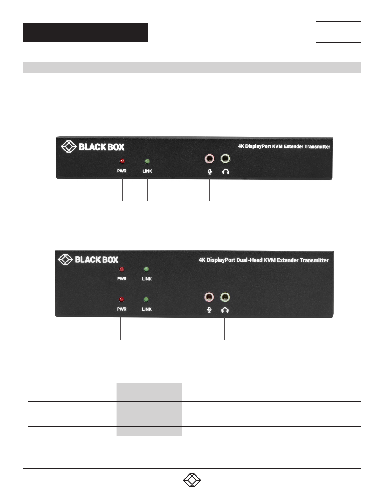
Figure 2-1 shows the front panel that is common the single-head CATx and the fiber transmitters. Table 2-1 describes the components.
1 2 3 4
FIGURE 2-1. SINGLE-HEAD TRANSMIT TER FRONT PANEL
Figure 2-2 shows the front panel that is common to the dual-head CATx and fiber transmitters. Table 2-1 describes the components.
1 2 3 4
FIGURE 2-2. DUAL-HEAD TRANSMITTER FRONT PANEL
TABLE 2-1. TRANSMITTER FRONT-PANEL COMPONENTS
NUMBE R IN FIGU RE 2-1 OR 2-2 COMPONENT DESCRIPTION
1 PWR LED Lights when power to the transmitter is ON
2 Link LED
3 Audio jack Connects to analog audio input for audio extension
4 Audio jack Connects to analog audio output for audio extension
1. 8 7 7. 8 7 7. 2 2 6 9 BLACK BOX .COM
Lights when the link between transmitter and receiver units is ON;
OFF when the link between transmitter and receiver units is OFF
7
Page 8
NEED HELP?
LEAV E TH E TEC H TO US
LIVE 24/7
CHAPTER 2: OVERVIEW
BACK PANEL
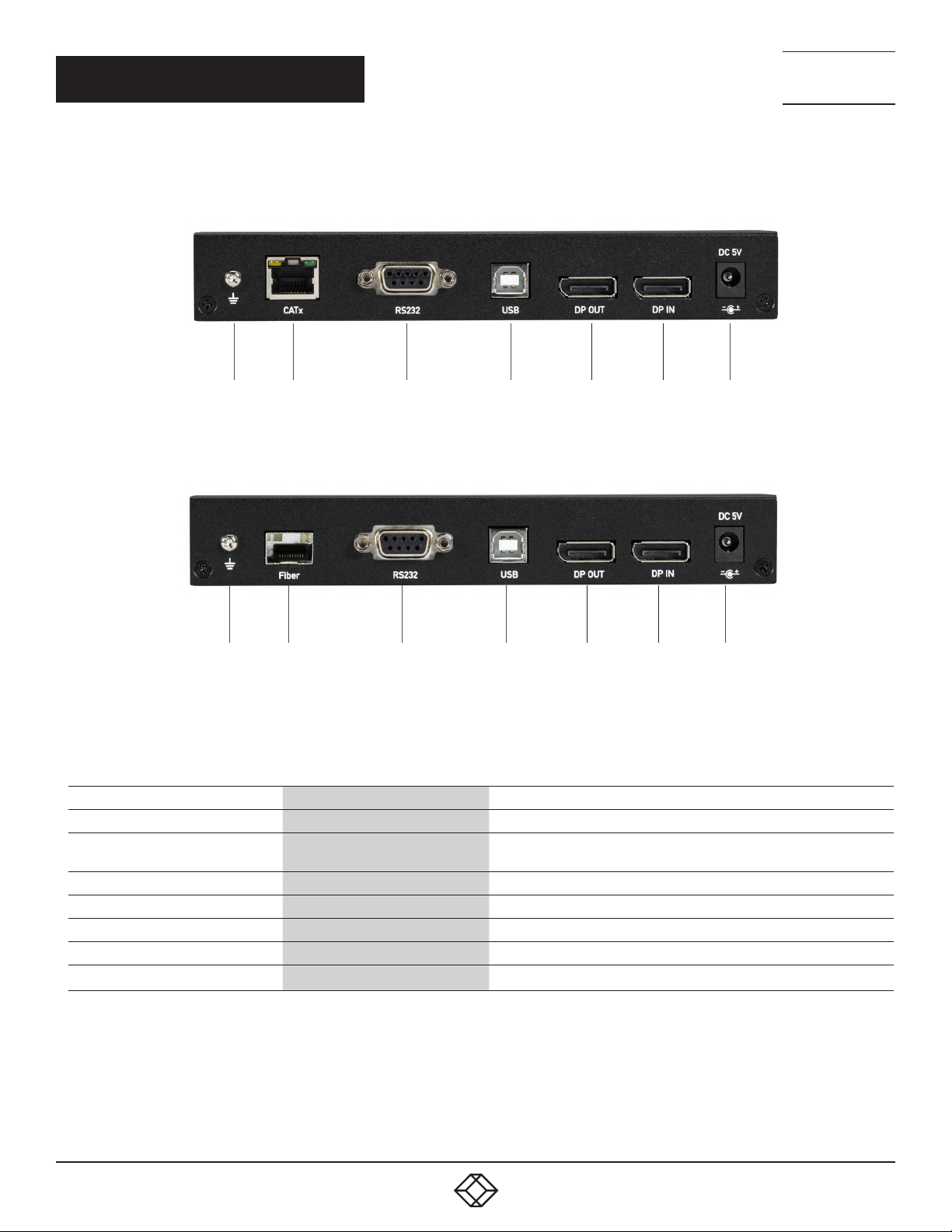
Figures 2-3 and 2-4 show the back panels of the single-head CATx and fiber transmitters. Table 2-2 describes their components.
1 2 3 4 5 6 7
FIGURE 2-3. SINGLE-HEAD CATX TR ANSMITTER BACK PANEL
TECHNICAL
SUPPORT
1. 8 7 7. 8 7 7. 2 2 69
1 2 3 4 5 6 7
FIGURE 2-4. SINGLE-HE AD FIBER TRANSMITTER BACK PANEL
TABLE 2-2. SINGLE-HEAD TRANSMITTER BACK-PANEL COMPONENTS
NUMBE R IN FIGU RE 2-3 OR 2-4 COMPONENT DESCRIPTION
1 Ground screw Links to ground
2
3 DB9 connector Connects to source device’s RS-232 port for serial extension
4 USB Type B connector Connects to source device’s USB port
5 DisplayPort Out port Connects to local out
6 DisplayPort In port Connects to source device’s signal for DisplayPort extension
7 Power connector Links to 5-VDC power supply
For CATx model: RJ-45 connector;
For Fiber model: SFP cage
For CATx Model: CATx link;
For Fiber model: Install fiber SFP module here
8
1. 8 7 7. 8 7 7. 2 2 6 9 BLACK BOX .COM
Page 9
NEED HELP?
LEAV E TH E TEC H TO US
LIVE 24/7
CHAPTER 2: OVERVIEW
TECHNICAL
SUPPORT
1. 8 7 7. 8 7 7. 2 2 69
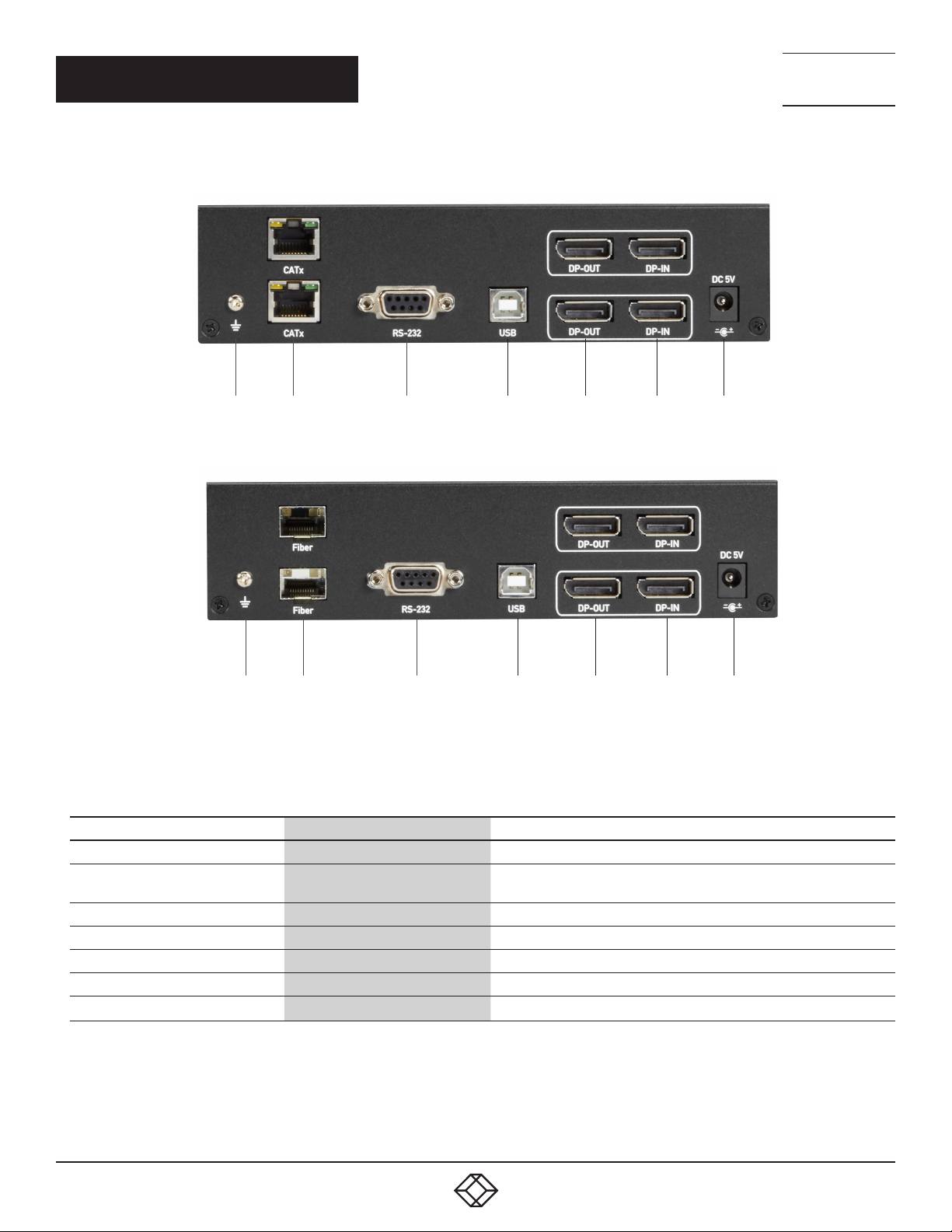
Figures 2-5 and 2-6 show the back panels of the dual-head CATx and fiber transmitters. Table 2-3 describes their components.
1 2 3 4 5 6 7
FIGURE 2-5.DUAL-HEAD CATX TRANSMITTER BACK PANEL
1 2 3 4 5 6 7
FIGURE 2-6. DUAL-HEAD FIBER TR ANSMITTER BACK PANEL
TABLE 2-3. DUAL-HEAD TRANSMITTER BACK-PANEL COMPONENTS
NUMBE R IN FIGU RE 2-5 OR 2-6 COMPONENT DESCRIPTION
1 Ground screw Links to ground
2
3 DB9 connector Connects to source device’s RS-232 port for serial extension
4 USB Type B connector Connects to source device’s USB port
5 (2) DisplayPort Out ports Connects to local outputs
6 (2) DisplayPort In ports Connects to source devices’ signals for DisplayPort extension
7 Power connector Links to 5-VDC power supply
For CATx model: RJ-45 connector;
For Fiber model: SFP cage
For CATx Model: CATx link;
For Fiber model: Install fiber SFP module here
1. 8 7 7. 8 7 7. 2 2 6 9 BLACK BOX .COM
9
Page 10
NEED HELP?
LEAV E TH E TEC H TO US
LIVE 24/7
CHAPTER 2: OVERVIEW
2.4.2 RECEIVER
FRONT PANEL
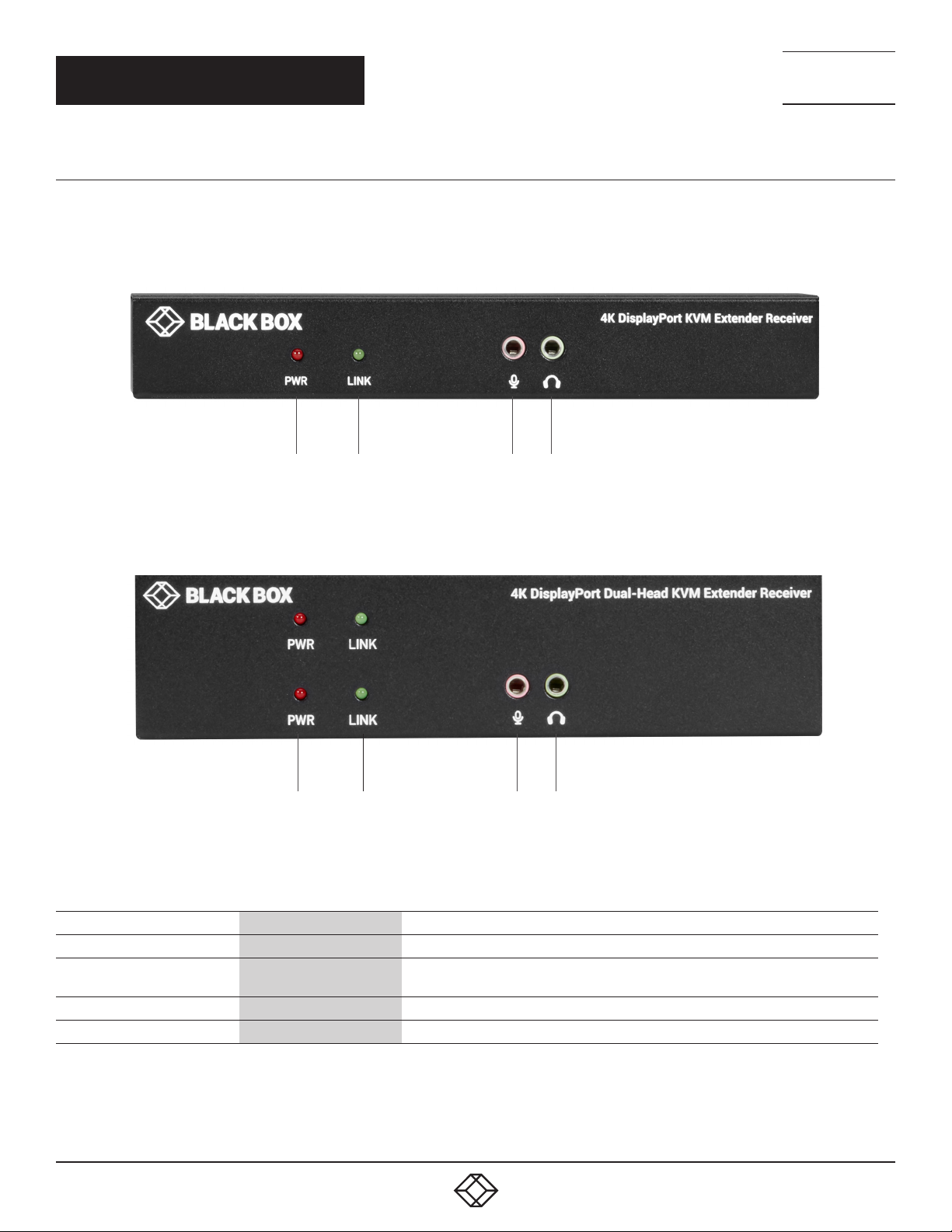
Figure 2-7 shows the front panel that is common to the single-head CATx and fiber receivers. Table 2-4 describes its components.
1 2 3 4
TECHNICAL
SUPPORT
1. 8 7 7. 8 7 7. 2 2 69
FIGURE 2-7. SINGLE-HE AD RECEIVER FRONT PANEL
Figure 2-8 shows the front panel that is common to the dual-head CATx and fiber receivers. Table 2-4 describes its components.
1 2 3 4
FIGURE 2-8. DUAL-HEAD RECEIVER FRONT PANEL
TABLE 2-4. RECEIVER FRONT-PANEL COMPONENTS
NUMBE R IN FIGU RE 2-4 COMPONENT DESCRIPTION
1 PWR LED Lights when power to the receiver is ON
2 Link LED
3 Audio jack Links to analog audio input for audio extension
4 Audio jack Links to analog audio output for audio extension
Lights when the link between transmitter and receiver units is ON;
OFF when the link between transmitter and receiver units is OFF
10
1. 8 7 7. 8 7 7. 2 2 6 9 BLACK BOX .COM
Page 11
NEED HELP?
LEAV E TH E TEC H TO US
LIVE 24/7
CHAPTER 2: OVERVIEW
BACK PANEL
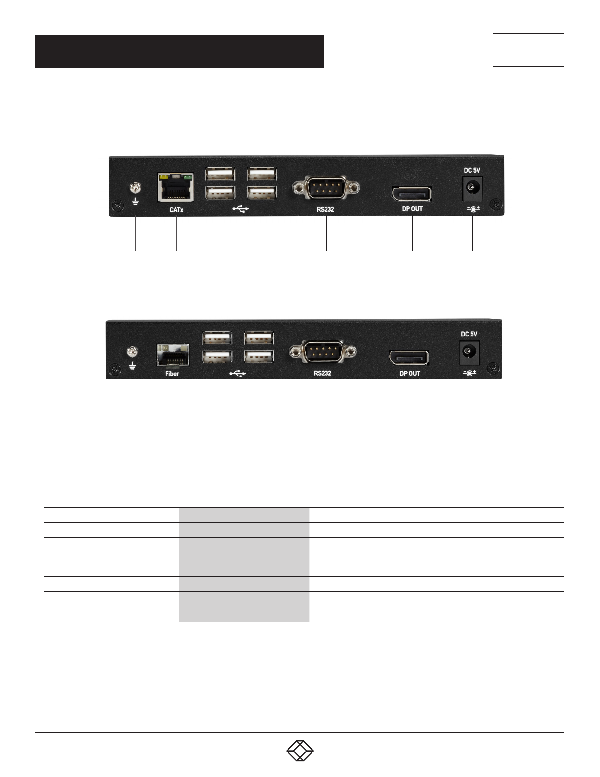
Figures 2-9 and 2-10 show the back panels of the single-head CATx and fiber receivers. Table 2-5 describes their components.
1 2 3 4 5 6
FIGURE 2-9. CATX RECEIVER BACK PANEL
TECHNICAL
SUPPORT
1. 8 7 7. 8 7 7. 2 2 69
1 2 3 4 5 6
FIGURE 2-10. FIBER RECEIVER BACK PANEL
TABLE 2-5. RECEIVER BACK-PANEL COMPONENTS
NUMBE R IN FIGU RE 2-9 OR 2-10 COMPONENT DESCRIPTION
1 Ground screw Links to ground
2
3 (4) USB 2.0 Type A ports Connect to USB device ports
4 DB9 connector Connects to sink device’s RS-232 por t for serial extension
5 DisplayPort Out port Connects to sink device’s signal for DisplayPort video extension
6 Power connector Links to 5-VDC power supply
For CATx model: RJ-45 connector
For Fiber model: SFP cage
For CATx Model: CATx link
For Fiber model: Install fiber SFP module here
1. 8 7 7. 8 7 7. 2 2 6 9 BLACK BOX .COM
11
Page 12
NEED HELP?
LEAV E TH E TEC H TO US
LIVE 24/7
CHAPTER 2: OVERVIEW
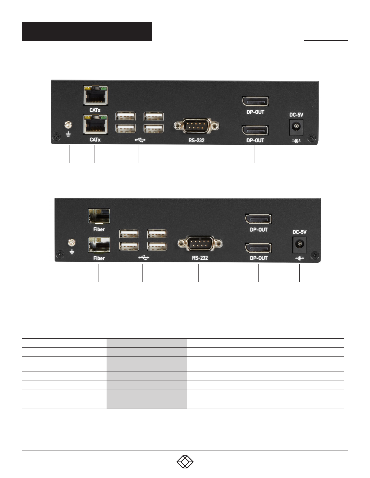
Figures 2-11 and 2-12 show the back panels of the dual-head CATx and fiber receivers. Table 2-6 describes their components.
1 2 3 4 5 6
FIGURE 2-11. DUAL-HEAD CATX RECEIVER BACK PANEL
TECHNICAL
SUPPORT
1. 8 7 7. 8 7 7. 2 2 69
1 2 3 4 5 6
FIGURE 2-12. DUAL-HEAD FIBER RECEIVER BACK PANEL
TABLE 2-6. DUAL-HEAD RECEIVER BACK-PANEL COMPONENTS
NUMBE R IN FIGU RE 2-11 OR 2-12 COMPONENT DESCRIPTION
1 Ground screw Links to ground
2
3 (4) USB 2.0 Type A ports Connect to USB device ports
4 DB9 connector Connects to sink device’s RS-232 port for serial extension
5 (2) DisplayPort Out ports Connects to sink devices' signals for DisplayPort video extension
6 Power connector Links to 5-VDC power supply
For CATx model: RJ-45 connector
For Fiber model: SFP cage
For CATx Model: CATx link
For Fiber model: Install fiber SFP module here
12
1. 8 7 7. 8 7 7. 2 2 6 9 BLACK BOX .COM
Page 13
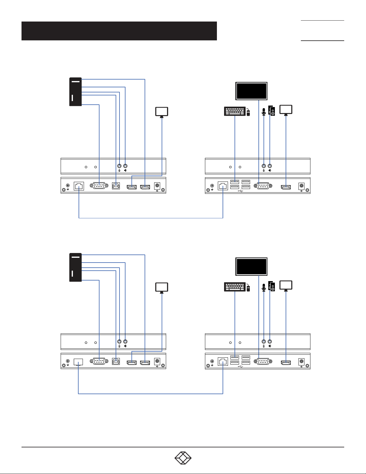
CHAPTER 3: CONNECTION DIAGRAM
Figures 3-1 and 3-2 show typical connections.
DisplayPort
Audio
Audio
USB
RS-232
DisplayPort
display
USB
keyboard/mouse
RS-232 device
DisplayPort
display
NEED HELP?
LEAV E TH E TEC H TO US
LIVE 24/7
TECHNICAL
SUPPORT
1. 8 7 7. 8 7 7. 2 2 69
CATx
RS232
TX uni t over CATx link
DisplayPort
Audio
Audio
USB
RS-232
USB
(KVX LCD P-10 0)
FIGURE 3-1. CATX MODEL CONNECTION DIAGRAM
DP OUT
DP IN
CATx cable
DC 5V
+
DisplayPort
display
USB
keyboard/mouse
DC 5V
-
CATx
RS232
DP OUT
+
RX uni t over CATx link
(KVX LCD P-10 0)
RS-232 device
DisplayPort
display
DC 5V
-
Fiber
USB
RS232
DP OUT
TX uni t over fiber lin k
(KVX LCD PF-100)
+
DP IN
CATx
RS232
RX uni t over fiber link
(KVX LCD PF-100)
DP OUT
DC 5V
+
Fiber cable
FIGURE 3-2. FIBER MODEL CONNECTION DIAGRAM
1. 8 7 7. 8 7 7. 2 2 6 9 BLACK BOX .COM
13
Page 14

NEED HELP?
LEAV E TH E TEC H TO US
LIVE 24/7
CHAPTER 4: INSTALLATION
Follow these steps to install the extender:
1. If you have the fiber models, install the SFPs in the transmitter and receiver. Compatible SFPs from Black Box are listed in the
table on page 3 of this manual.
NOTE: Other SFPs may work but have not been validated by Black Box, we recommend you use the suggested SFPs to avoid
technical incompatibilities.
NOTE: SFP is not included, must be ordered separately.
2. Connect one end of a DisplayPort cable to the DisplayPort port on the source device (e.g. computer, server or other IT device).
Then connect the other end to the DisplayPort IN port located on the TX unit.
3. Connect the DisplayPort display to the DisplayPort OUT port on the TX unit.
4. Connect the DisplayPort display to the DisplayPort OUT port on the RX unit.
5. Connect the USB ports of the source device and the TX unit with a USB type A-B cable. Then plug a USB keyboard, mouse, or
other USB devices into the USB ports of the RX unit.
6. Connect the RS-232 ports of the source device and the TX unit. Then connect the RS-232 ports of the RS-232 device on the RX
unit side and the RX unit.
7. Connect the microphone/speaker ports of the source device and the TX unit with the audio microphone/speaker combo cable.
Then, plug the microphone and speaker into the microphone and speaker ports of the RX unit.
8. For the CATx model, use a CAT5e cable to connect the CATx link ports on the TX unit and the RX unit.
9. For the fiber model, use two SFP modules and an optical fiber cable to connect the fiber link ports on the TX unit and the RX unit.
10. Plug the power adapter cable into the DC jacks on the TX and RX units.
NOTES:
a. We recommend using the highest quality materials (cables, SFP, etc.) to ensure optimal transmission quality.
b. If the screen does not display when you connect the computer:
1. Make sure the device cables are correctly and firmly attached.
2. Set your display device’s (TV, monitor, etc.) input source as DisplayPort.
3. Check the PC BIOS configuration of the video output setting.
4. Connect your video source to the Display DIRECTLY to check if the video signal gets through.
TECHNICAL
SUPPORT
1. 8 7 7. 8 7 7. 2 2 69
NOTES:
1. Both the DisplayPort displays respectively connecting to TX and RX units MUST support the same maximum video resolution.
2. SFP module’s bandwidth requirement is 1 Gbps minimum.
3. When plugging into any microphone or speaker ports of TX or RX units, digital DisplayPort audio extension will be disabled and
only analog audio LINE-IN/LINE-OUT extension is enabled.
14
1. 8 7 7. 8 7 7. 2 2 6 9 BLACK BOX .COM
Page 15

NEED HELP?
LEAV E TH E TEC H TO US
LIVE 24/7
APPENDIX A: REGULATORY INFORMATION
TECHNICAL
SUPPORT
1. 8 7 7. 8 7 7. 2 2 69
A.1 FCC CLASS A STATEMENT
This equipment generates, uses, and can radiate radio-frequency energy, and if not installed and used properly, that is, in strict
accordance with the manufacturer’s instructions, may cause interference to radio communication. It has been tested and found to
comply with the limits for a Class A computing device in accordance with the specifications in Subpart B of Part 15 of FCC rules,
which are designed to provide reasonable protection against such interference when the equipment is operated in a commercial
environment. Operation of this equipment in a residential area is likely to cause interference, in which case the user at his own
expense will be required to take whatever measures may be necessary to correct the interference.
Changes or modifications not expressly approved by the party responsible for compliance could void the user’s authority to
operate the equipment.
This digital apparatus does not exceed the Class A limits for radio noise emission from digital apparatus set out in the Radio
Interference Regulation of Industry Canada.
Le présent appareil numérique n’émet pas de bruits radioélectriques dépassant les limites applicables aux appareils numériques
de la classe A prescrites dans le Règlement sur le brouillage radioélectrique publié par Industrie Canada.
1. 8 7 7. 8 7 7. 2 2 6 9 BLACK BOX .COM
15
Page 16

NEED HELP?
LEAV E TH E TEC H TO US
LIVE 24/7
APPENDIX A: REGULATORY INFORMATION
TECHNICAL
SUPPORT
1. 8 7 7. 8 7 7. 2 2 69
A.2 NOM STATEMENT
1. Todas las instrucciones de seguridad y operación deberán ser leídas antes de que el aparato eléctrico sea operado.
2. Las instrucciones de seguridad y operación deberán ser guardadas para referencia futura.
3. Todas las advertencias en el aparato eléctrico y en sus instrucciones de operación deben ser respetadas.
4. Todas las instrucciones de operación y uso deben ser seguidas.
5. El aparato eléctrico no deberá ser usado cerca del agua—por ejemplo, cerca de la tina de baño, lavabo, sótano mojado o cerca de
una alberca, etc.
6. El aparato eléctrico debe ser usado únicamente con carritos o pedestales que sean recomendados por el fabricante.
7. El aparato eléctrico debe ser montado a la pared o al techo sólo como sea recomendado por el fabricante.
8. Servicio—El usuario no debe intentar dar servicio al equipo eléctrico más allá a lo descrito en las instrucciones de operación.
Todo otro servicio deberá ser referido a personal de servicio calificado.
9. El aparato eléctrico debe ser situado de tal manera que su posición no interfiera su uso. La colocación del aparato eléctrico
sobre una cama, sofá, alfombra o superficie similar puede bloquea la ventilación, no se debe colocar en libreros o gabinetes que
impidan el flujo de aire por los orificios de ventilación.
10. El equipo eléctrico deber ser situado fuera del alcance de fuentes de calor como radiadores, registros de calor, estufas u otros
aparatos (incluyendo amplificadores) que producen calor.
11. El aparato eléctrico deberá ser connectado a una fuente de poder sólo del tipo descrito en el instructivo de operación, o como
se indique en el aparato.
12. Precaución debe ser tomada de tal manera que la tierra fisica y la polarización del equipo no sea eliminada.
13. Los cables de la fuente de poder deben ser guiados de tal manera que no sean pisados ni pellizcados por objetos colocados
sobre o contra ellos, poniendo particular atención a los contactos y receptáculos donde salen del aparato.
14. El equipo eléctrico debe ser limpiado únicamente de acuerdo a las recomendaciones del fabricante.
15. En caso de existir, una antena externa deberá ser localizada lejos de las lineas de energia.
16. El cable de corriente deberá ser desconectado del cuando el equipo no sea usado por un largo periodo de tiempo.
17. Cuidado debe ser tomado de tal manera que objectos liquidos no sean derramados sobre la cubierta u orificios de ventilación.
18. Servicio por personal calificado deberá ser provisto cuando:
A: El cable de poder o el contacto ha sido dañado; u
B: Objectos han caído o líquido ha sido derramado dentro del aparato;o
C: El aparato ha sido expuesto a la lluvia; o
D: El aparato parece no operar normalmente o muestra un cambio en su desempeño; o
E: El aparato ha sido tirado o su cubierta ha sido dañada.
16
1. 8 7 7. 8 7 7. 2 2 6 9 BLACK BOX .COM
Page 17

NEED HELP?
LEAV E TH E TEC H TO US
LIVE 24/7
APPENDIX B: DISCLAIMER/TRADEMARKS
TECHNICAL
SUPPORT
1. 8 7 7. 8 7 7. 2 2 69
B.1 DISCLAIMER
Black Box Corporation shall not be liable for damages of any kind, including, but not limited to, punitive, consequential or cost of cover
damages, resulting from any errors in the product information or specifications set forth in this document and Black Box Corporation
may revise this document at any time without notice.
B.2 TRADEMARKS USED IN THIS MANUAL
Black Box and the Black Box logo type and mark are registered trademarks of Black Box Corporation.
Any other trademarks mentioned in this manual are acknowledged to be the property of the trademark owners.
1. 8 7 7. 8 7 7. 2 2 6 9 BLACK BOX .COM
17
Page 18

NOTES
__________________________________________________________________________________________________
__________________________________________________________________________________________________
__________________________________________________________________________________________________
__________________________________________________________________________________________________
__________________________________________________________________________________________________
__________________________________________________________________________________________________
NEED HELP?
LEAV E TH E TEC H TO US
LIVE 24/7
TECHNICAL
SUPPORT
1. 8 7 7. 8 7 7. 2 2 69
__________________________________________________________________________________________________
_
_________________________________________________________________________________________________
__________________________________________________________________________________________________
__________________________________________________________________________________________________\
__________________________________________________________________________________________________
__________________________________________________________________________________________________
__________________________________________________________________________________________________
__________________________________________________________________________________________________
_________________________________________________________________________________________________
18
__________________________________________________________________________________________________
__________________________________________________________________________________________________
__________________________________________________________________________________________________
1. 8 7 7. 8 7 7. 2 2 6 9 BLACK BOX .COM
Page 19

NOTES
__________________________________________________________________________________________________
__________________________________________________________________________________________________
__________________________________________________________________________________________________
__________________________________________________________________________________________________
__________________________________________________________________________________________________
__________________________________________________________________________________________________
NEED HELP?
LEAV E TH E TEC H TO US
LIVE 24/7
TECHNICAL
SUPPORT
1. 8 7 7. 8 7 7. 2 2 69
__________________________________________________________________________________________________
_
_________________________________________________________________________________________________
__________________________________________________________________________________________________
__________________________________________________________________________________________________\
__________________________________________________________________________________________________
__________________________________________________________________________________________________
__________________________________________________________________________________________________
__________________________________________________________________________________________________
_________________________________________________________________________________________________
__________________________________________________________________________________________________
__________________________________________________________________________________________________
__________________________________________________________________________________________________
1. 8 7 7. 8 7 7. 2 2 6 9 BLACK BOX .COM
19
Page 20

NEED HELP?
LEAVE THE TECH TO US
LIVE 24/7
TECHNICAL
SUPPORT
1.877.87 7.226 9
© COPYRIGHT 2019, 2021. BLACK BOX CORPORATION. ALL RIGHTS RESERVED.
KVXLCDP-100_200_QIG-USER_REV6.PDF
 Loading...