

Black Box KVT517A-1UV, KVT517A-16PV, KVT517A-16UV, KVT517A-8UV, KVT517A-8PV User Manual
...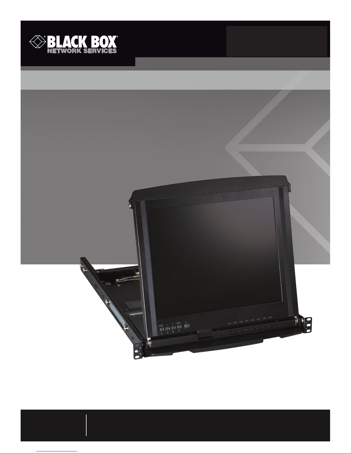
ServView V KVM Tray
Control your 4-post rack- or cabinet-mounted
USB or PS/2 server with the compact
ServView V KVM tray.
Widescreen model is now available.
May 2010
KV T517A -1UV KV T517A -16PV
KV T517A -8 PV KV T517A -16U V
KV T517A -8 UV KV T517A -8 DV- WIDE
Customer
Support
Information
Order toll-free in the U.S.: Call 877-877-BBOX (outside U.S. call 724-746-5500) •
FREE technical support 24 hours a day, 7 days a week: Call 724-746-5500 or fax 724-746-0746 •
Mailing address: Black Box Corporation, 1000 Park Drive, Lawrence, PA 15055-1018 •
Web site: www.blackbox.com • E-mail: info@blackbox.com

ServView V KVM Tray
Trademarks Used in This Manual
Black Box and the Double Diamond logo are registered trademarks, and ServView and ServSwitch are trademarks, of
BB Technologies, Inc.
Centronics is a registered trademark of Centronics Corporation.
PS/2 is a registered trademark of International Business Machines Corporation.
UL is a registered trademark of Underwriters Laboratories Inc.
Any other trademarks mentioned in this manual are acknowledged to be the property of the trademark owners.
We‘re here to help! If you have any questions about your application
or our products, contact Black Box Tech Support at 724-746-5500
or go to blackbox.com and click on “Talk to Black Box.”
You’ll be live with one of our technical experts in less than 20 seconds.
Page 2
724-746-5500 | blackbox.com

FCC and IC RFI Statements
Federal Communications Commission and Industry Canada Radio Frequency Interference
Statements
This equipment generates, uses, and can radiate radio-frequency energy, and if not installed and used properly, that is, in strict
accordance with the manufacturer’s instructions, may cause inter ference to radio communication. It has been tested and found to
comply with the limits for a Class A computing device in accordance with the specifications in Subpart B of Part 15 of FCC rules,
which are designed to provide reasonable protection against such interference when the equipment is operated in a commercial
environment. Operation of this equipment in a residential area is likely to cause interference, in which case the user at his own
expense will be required to take whatever measures may be necessary to correct the interference.
Changes or modifications not expressly approved by the party responsible for compliance could void the user’s authority to
operate the equipment.
This digital apparatus does not exceed the Class A limits for radio noise emis sion from digital apparatus set out in the Radio
Interference Regulation of Industry Canada.
Le présent appareil numérique n’émet pas de bruits radioélectriques dépassant les limites applicables aux appareils numériques de
la classe A prescrites dans le Règlement sur le brouillage radioélectrique publié par Industrie Canada.
Page 3

ServView V KVM Tray
Instrucciones de Seguridad
(Normas Oficiales Mexicanas Electrical Safety Statement)
1. Todas las instrucciones de seguridad y operación deberán ser leídas antes de que el aparato eléctrico sea operado.
2. Las instrucciones de seguridad y operación deberán ser guardadas para referencia futura.
3. Todas las advertencias en el aparato eléctrico y en sus instrucciones de operación deben ser respetadas.
4. Todas las instrucciones de operación y uso deben ser seguidas.
5. El aparato eléctrico no deberá ser usado cerca del agua—por ejemplo, cerca de la tina de baño, lavabo, sótano mojado o cerca
de una alberca, etc.
6. El aparato eléctrico debe ser usado únicamente con carritos o pedestales que sean recomendados por el fabricante.
7. El aparato eléctrico debe ser montado a la pared o al techo sólo como sea recomendado por el fabricante.
8. Servicio—El usuario no debe intentar dar servicio al equipo eléctrico más allá a lo descrito en las instrucciones de operación.
Todo otro servicio deberá ser referido a personal de servicio calificado.
9. El aparato eléctrico debe ser situado de tal manera que su posición no interfiera su uso. La colocación del aparato eléctrico
sobre una cama, sofá, alfombra o superficie similar puede bloquea la ventilación, no se debe colocar en libreros o gabinetes
que impidan el flujo de aire por los orificios de ventilación.
10. El equipo eléctrico deber ser situado fuera del alcance de fuentes de calor como radiadores, registros de calor, estufas u otros
aparatos (incluyendo amplificadores) que producen calor.
11. El aparato eléctrico deberá ser connectado a una fuente de poder sólo del tipo descrito en el instructivo de operación, o como
se indique en el aparato.
12. Precaución debe ser tomada de tal manera que la tierra fisica y la polarización del equipo no sea eliminada.
13. Los cables de la fuente de poder deben ser guiados de tal manera que no sean pisados ni pellizcados por objetos colocados
sobre o contra ellos, poniendo particular atención a los contactos y receptáculos donde salen del aparato.
14. El equipo eléctrico debe ser limpiado únicamente de acuerdo a las recomendaciones del fabricante.
15. En caso de existir, una antena externa deberá ser localizada lejos de las lineas de energia.
16. El cable de corriente deberá ser desconectado del cuando el equipo no sea usado por un largo periodo de tiempo.
17. Cuidado debe ser tomado de tal manera que objectos liquidos no sean derramados sobre la cubierta u orificios de ventilación.
18. Servicio por personal calificado deberá ser provisto cuando:
A: El cable de poder o el contacto ha sido dañado; u
B: Objectos han caído o líquido ha sido derramado dentro del aparato; o
C: El aparato ha sido expuesto a la lluvia; o
D: El aparato parece no operar normalmente o muestra un cambio en su desempeño; o
E: El aparato ha sido tirado o su cubierta ha sido dañada.
Page 4
724-746-5500 | blackbox.com

Table of Contents
1. Specifications ...................................................................................................................................................................6
2. Overview ...................................................................................................................................................................7
2.1 Introduction ............................................................................................................................................................... 7
2.2 What’s Included......................................................................................................................................................... 8
2.3 ServView V KVM Tray Kit Part Numbers ...................................................................................................................8
2.4 1U-Height KVM Switch Function Modules ................................................................................................................ 9
2.5 Rear Bracket Extensions ............................................................................................................................................. 9
3. Assembly and Installation .................................................................................................................................................... 11
3.1 Assembly ................................................................................................................................................................. 11
3.2 Installation ............................................................................................................................................................... 17
4. Operation ................................................................................................................................................................. 19
4.1 KVM Control and Status LEDs ................................................................................................................................. 19
4.2 Extra Keyboard and Mouse Control ........................................................................................................................ 21
4.3 Opening and Closing the Console ...........................................................................................................................22
4.3.1 Opening the Console ....................................................................................................................................22
4.3.2 Closing the Console ...................................................................................................................................... 24
4.3.3 Opening the Keyboard/ Touch Pad and LCD Monitor Individually ................................................................. 25
4.4 Replacing the Keyboard and Touch Pad .................................................................................................................. 26
4.4.1 Removing the Keyboard ................................................................................................................................ 26
4.4.2 Replacing the Keyboard ................................................................................................................................ 27
4.4.3 Alternate Way to Fasten the Keyboard (Recommended) ............................................................................... 29
4.4.4 Replacing the Touch Pad ...............................................................................................................................30
5. Troubleshooting ................................................................................................................................................................. 32
5.1 Calling Black Box .....................................................................................................................................................32
5.2 Shipping and Packaging .......................................................................................................................................... 32
Page 5

ServView V KVM Tray
1. Specifications
Specification KVT517A models KVT517A-WIDE model
Active Display Area: 10.6"H x 13.3"W (27 x 33.8 cm) 9"H x 14.5"W (22.9 x 36.7 cm)
Approvals: CE, FCC for the product; UL®, TUV, CE, FCC for the product; UL®, TUV,
CE for power supply CE for power supply
Backlight Unit: 4 CCFLs edge-light (top/bottom) 4 CCFLs edge-light (top/bottom)
Brightness (cd/m^2): 300 (center) 400 center
Contrast Ratio (Typical): 800 :1 50 0:1
Display Color (RGB 6-bits
+ FRC data): 16.2 M 16.2 M
Display Mode: Normally white Normally white
Input Signal: RGB analog, H/V separate RGB analog, H/V separate
Pixel Pitch: 0.264 mm (H) x 0.264 mm (V) 0.191 mm (H) x 0.190 mm (V)
Plug-n-Play VESA: VESA DDC 1/2B VESA DDC 1/2B
Resolution: 1280 x 1024 @ 60/70/75 Hz 1920 x 1080P
VGA Resolution for Optimum
Performance: 1280 x 1024 @60 Hz 1920 x 1080P
' Viewing Angle (Typical): -80 to +80 (H), -80 to +80 -70 to +70 (H), -60 to +60
Connectors: (1) Centronics® female (1) Centronics female
Temperature: Operating: +32 to +122° F (0 to +50° C); Operating: +32 to +122° F (0 to +50° C);
Storage: -4 to +140° F (-20 to +60° C) Storage: -4 to +140° F (-20 to +60° C)
Humidity (Relative): Operating: 8–95%; Operating: 8–95%;
Storage: Less than or equal to 95% Storage: Less than or equal to 95%
Power Consumption 37 watts 13.6 watts
(Maximum, Typical):
Power: 12 VDC (from external 100–240-VAC 12 VDC (from external 100–240-VAC
power adapter), 47–63 Hz power adapter), 47–63 Hz
Size: 1.75"H (1U) x 17"W x 19.5" to 39.5"D 1.75"H (1U) x 17"W x 19.5" to 39.5"D
(4.4 x 43.2 x 49.5 to 100.3 cm) (4.4 x 43.2 x 49.5 to 100.3 cm)
Weight: 23 lb. (10.4 kg) 23 lb. (10.4 kg)
Page 6
724-746-5500 | blackbox.com
Chapter 2: Overview
2. Overview
2.1 Introduction
Each ServView™ V KVM Tray Kit includes a KVM Tray (KVT517A or KVT517A-WIDE), a KVM module (KVT4S1UV, KVT4S8PV,
KVT4S8UV, KVT4S16PV, KVT4S16UV, or KVT8DVIU), and a universal rear bracket extension kit. This manual describes how to use
the ServView V KVM Tray and the rear bracket extension kit, and a separate manual (included with your kit) explains how to use
the KVM module.
Control your 4-post-rack- or cabinet-mounted USB or PS/2® server with the compact, easy-to-use ServView V KVM Tray. It consists of a keyboard, mouse, LCD panel, and KVM module housed in an industry-standard 19" 1U-height rack drawer (see Figure
2-1). The unique dual-rail design allows the keyboard and LCD display to slide in and out independently of each other, so you can
stow the keyboard out of the way when you’re not using it.
The ServView has a 17" standard or widescreen LCD panel. It features a full 105-key, low-profile, sturdy keyboard and touch pad
with an ergonomically designed hand rest. The KVT517A has a maximum resolution of 1280 x 1024. The KVT517A-WIDE has a
maximum resolution of 1920 x 1080P.
Install the ServView in 4-post racks or cabinets that have rail space of 23.7"D to 45.3"D (60.2 to 115.1 cm).
NOTE: This is the depth measured between the front pole and rear pole inside a 4-post rack or cabinet, not the outside depth of
the enclosure.
When installing the ServView, you’ll need to use the universal Rear Bracket Extension Kit that’s included in your ServView Kit.
A KVM module is also included with the ServView. To control more than one USB or PS/2 server, connect the ServView to a
ServSwitch™.
The KVM module comes with a universal Centronics® 36-pin connector; use it to connect the module to the console drawer. The
module has a barrel connector for power. The small screws (0.12" x 0.24" [0.5 x 1.1 cm]) listed in Section 2.2 secure the brackets
to the KVM module. The large screws (0.19" x 0.43" [0.3 x 0.6 cm]) are used in place of 10-32 or 12-24 screws (described in
Chapter 3, not included) if required by your rack.
Universal rear bracket
extension kit
KVM module
(KVT4S1UV, KVT4S8PV,
KVT4S8UV, KVT4S16PV,
KVT4S16UV,
or KVT8DVIU)
1U dual-rail slide drawer
with keyboard, touch pad,
and 17" monitor (KVT517A
or KVT517A-WIDE)
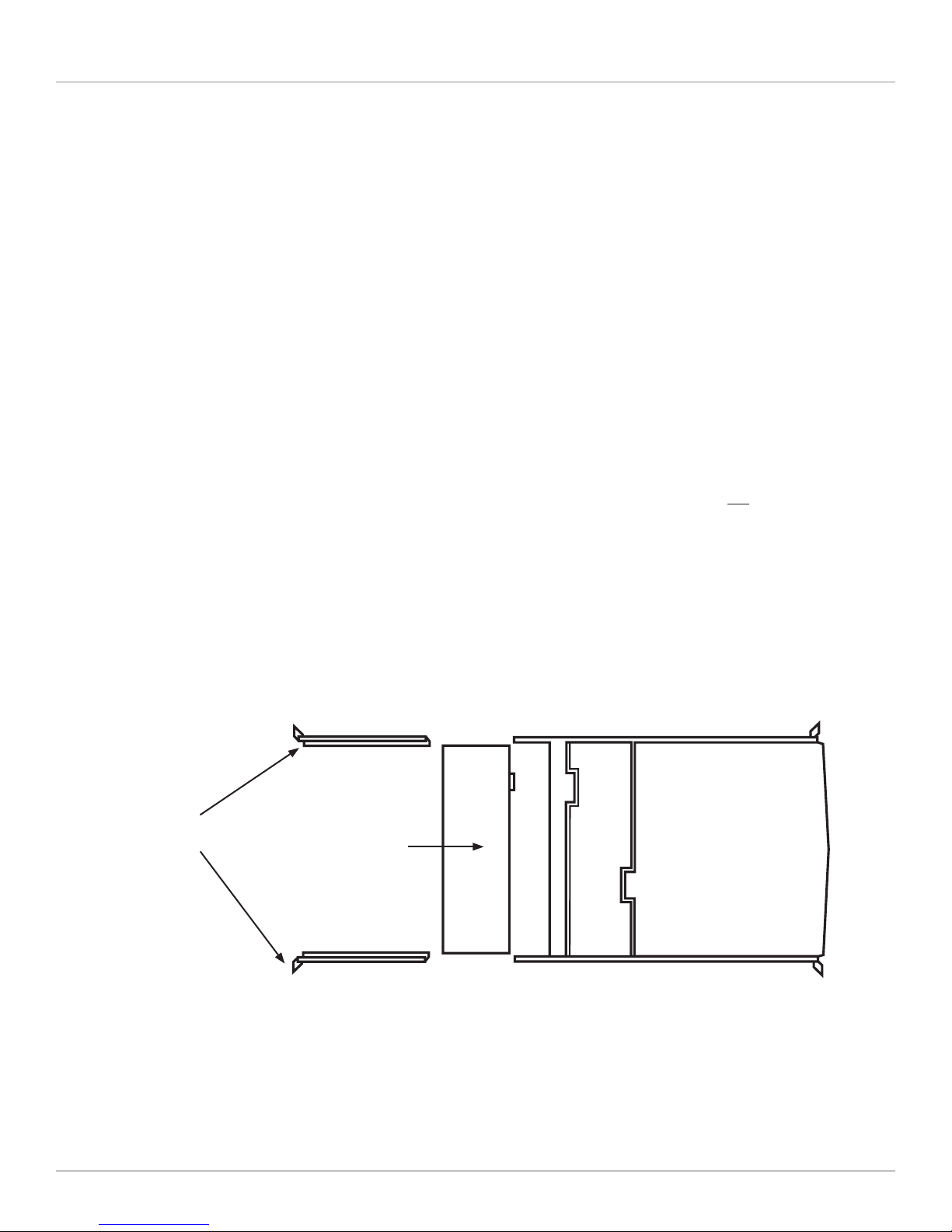
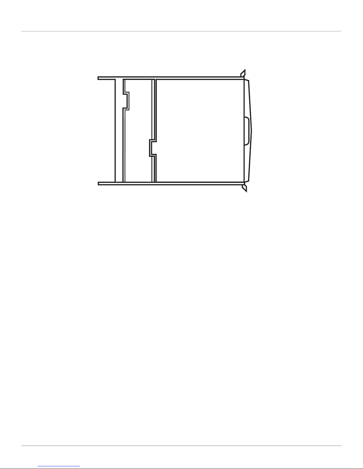
Figure 2-1. ServView Kit components (left to right): Rear Bracket Extension Kit,
KVM Module with power supply, and 1U slide drawer.
Page 7
ServView V KVM Tray
Figure 2-2. ServView V Tray, closed position.
2.2 What’s Included
• (1) 1U dual-rail drawer with keyboard, touch pad, and LCD monitor
• (1) KVM module with power supply (based on product code)
• (1) universal rear rail kit (includes [2] brackets, [2] extenders, and [8] screws)
• (10) 0.19" x 0.43" (0.5 x 1.1 cm) screws
• (10) 0.12" x 0.24" (0.3 x 0.6 cm) screws
• This user’s manual
You might also need 12-24 or 10-32 nuts/bolts.
2.3 ServView V KVM Tray Kit Part Numbers
The ServView V KVM Tray Kit includes a ServView V KVM Tray, a PS/2 or USB KVM module, and a universal rear bracket extension kit. Table 2-1 lists the available kits.
Table 2-1. ServView V KVM Tray Kit components.
Kit Part Number KVM Module P/N Link Rail Depths
KVT517A-1UV KVT4S1UV 1-port VGA USB/PS2 23.7"–45.3"
KVT517A-8UV KVT4S8UV 8-port VGA USB/PS2 23.7"–45.3"
KVT517A-16UV KVT4S16UV 16-port VGA USB/PS2 23.7"–45.3"
KVT517A-8PV KVT4S8PV 8-port VGA PS/2 23.7"–45.3"
KVT517A-16PV KVT4S16PV 16-port VGA PS/2 23.7"–45.3"
KVT517A-8DV-WIDE KVT8DVIU 8-port DVI USB 23.7"–45.3"
Page 8
724-746-5500 | blackbox.com
Chapter 2: Overview
2.4 1U-Height KVM Switch Function Modules
When a 1U KVM switch function module is slid into the rear side of the console drawer, the entire setup takes 1U space of a rack
or cabinet. Table 2-2 describes the available 1U-height modules.
Table 2-2. 1U-height KVM Switch Function Modules.
Part Number Interface
KVT4S1UV 1-port PS/2 or USB
KVT4S8PV 8-port PS/2
KVT4S8UV 8-port PS/2 or USB
K V T4S16PV 16-port PS/2
KVT4S16UV 16-port PS/2 or USB
KV T517A-8DV-W ID E 8-por t USB
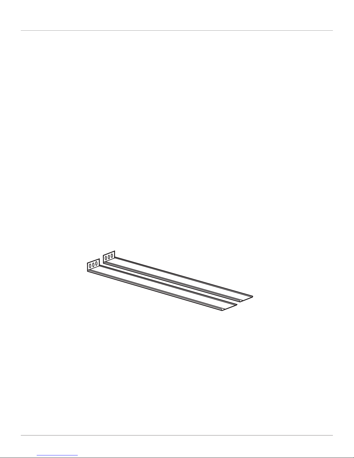
2.5 Rear Bracket Extensions
Figure 2-3 shows the rear bracket pair, and Figures 2-4 and 2-5 show the ServView V in its maximum and minimum extension
positions.
Figure 2-3. Rear bracket pair.
NOTE: The lengths in Figures 2-4 and 2-5 are the depths measured between the front pole and rear pole inside a 4-post rack
or cabinet, not the outside depth of the enclosure.
Page 9

ServView V KVM Tray
45.3" (115.1 cm)
Figure 2-4. The maximum depth of the unit.
Open rack
post 1
23.7" (60.2 cm)
Figure 2-5. The minimum depth of the unit.
Open rack
post 2
ServView V Tray
Figure 2-6. ServView V Tray installed on an open rack.
Page 10
724-746-5500 | blackbox.com
 Loading...