

Page 1
USER GUIDE
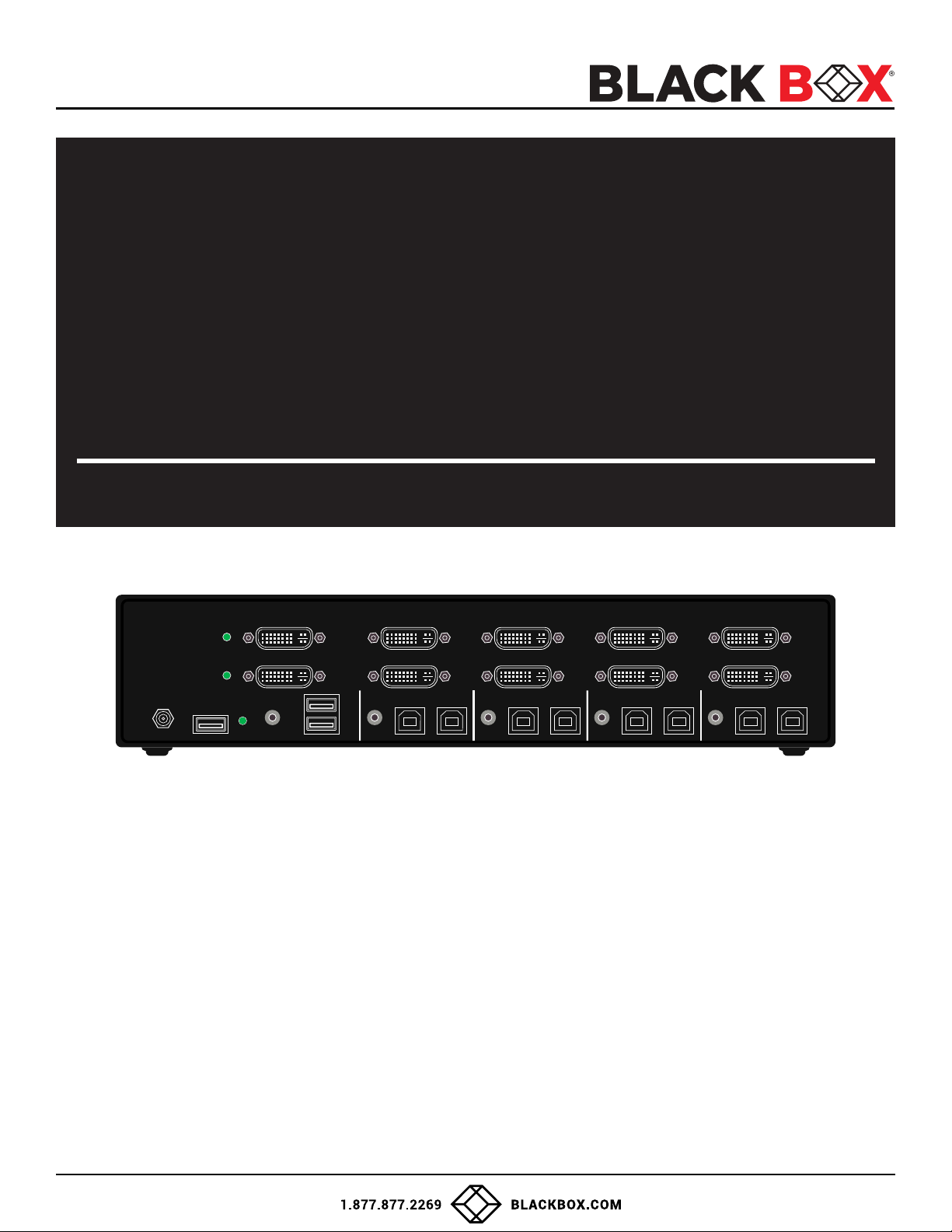
KVS4-2004DX
1 2 3 4ST1 ST2
ADVANCED 2/4/8-PORT
DVI-I SECURE KVM
SWITCH
USM-2S0-MM6 REV: 3.0A 05/19/2022
DVI-I OUT B DVI-I IN4 B DVI-I IN3 B DVI-I IN2 B DVI-I IN1 B
CONSOLE
12VDC
DVI-I OUT A DVI-I IN4 A DVI-I IN3 A DVI-I IN2 A DVI-I IN1 A
CAC
AUDIO
K/M
K/M K/M K/M K/M
AUDIO AUDIO AUDIO AUDIO
CAC CAC CAC CAC
MODELS:
• KVS4-1002D 2-Port SH Secure Pro DVI-I KVM w/audio, NO CAC
• KVS4-2002D 2-Port DH Secure Pro DVI-I KVM w/audio, NO CAC
• KVS4-1004D 4-Port SH Secure Pro DVI-I KVM w/audio, NO CAC
• KVS4-2004D 4-Port DH Secure Pro DVI-I KVM w/audio, NO CAC
• KVS4-2004DX 4-Port DH Secure Pro DVI-I KVM w/audio and CAC
• KVS4-1008DX 8-Port SH Secure Pro DVI-I KVM w/ audio and CAC
• KVS4-2008D 8-Port DH Secure Pro DVI-I KVM w/ audio, NO CAC
• KVS4-2008DX 8-Port DH Secure Pro DVI-I KVM w/ audio and CAC
IN-1IN-2IN-3IN-4
1
Page 2

USER GUIDE
TABLE OF CONTENTS
TECHNICAL SPECIFICATIONS
WHAT’S IN THE BOX?
SECURITY FEATURES
FRONT AND REAR
INSTALLATION
CAC INSTALLATION: COMMON ACCESS CARD, SMART CARD READER
CAC PORT CONFIGURATION
AUDITING: Dumping the Event Log via User Menu Options
RESET: Restore Factory Default
LED’s BEHAVIOR
SYSTEM OPERATION
TROUBLESHOOTING
TECHNICAL SUPPORT
3
4
4
4
5
10
10
11
11
12
13
13
13
LIMITED WARRANTY STATEMENT
14
2
Page 3

USER GUIDE
TECHNICAL SPECIFICATIONS
VIDEO
Format DVI-I Dual Link
KVS4-1002D (2) DVI-I 29-pin (female)
Host Interface
User Console Interface
Max Resolution 2560 x 1600 @ 60Hz; 3840x2160 @ 30Hz (w/HDMI-to-DVI adapter)
DDC 5 volts p-p (TTL)
Input Equalization Automatic
Input Cable Length Up to 20 ft.
Output Cable Length Up to 20 ft.
USB
Signal Type USB 1.1 and 1.0 Keyboard and Mouse only. USB 2.0 for CAC connection (Only in models with CAC)
Type B
User Console Interface
AUDIO
Input
Output (1) Connector Stereo 3.5mm Female
POWER
Power Requirements 12V DC, 3A (minimum) power adapter with center-pin positive polarity.
ENVIRONMENT
Operating Temp 32° to 104° F (0° to 40° C)
Storage Temp -4° to 140° F (-20° to 60° C)
Humidity 0-80% RH, non-condensing
CERTIFICATIONS
Security Accreditation
OTHER
Emulation Keyboard, Mouse and Video
Control Front Panel Buttons
KVS4-2002D / KVS4-1004D (4) DVI-I 29-pin (female)
KVS4-2004D / KVS4-2004DX / KVS4-1008DX (8) DVI-I 29-pin (female)
KVS4-2008D / KVS4-2008DX (16) DVI-I 29-pin (female)
KVS4-1002D / KVS4-1004D / KVS4-1008DX
KVS4-2002D / KVS4-2004D / KVS4-2004DX /
KVS4-2008D / KVS4-2008DX
KVS4-1002D / KVS4-2002D (2) USB Type B
KVS4-1004D / KVS4-2004D (4) USB Type B
KVS4-2004DX / KVS4-1008DX / KVS4-2008D (8) USB Type B
KVS4-2008DX (16) USB Type B
(2) USB Type-A for keyboard and mouse connection only
(1) USB Type-A for CAC connection (only in models with CAC)
(2)/(4)/(8) Connector Stereo 3.5mm Female
Common Criteria Validated To NIAP, Protection Prole PSS Ver. 4.0
(1) DVI-I 29-pin (female)
(2) DVI-I 29-pin (female)
3
Page 4
USER GUIDE
KVS4-2004DX
1 2 3 4ST1 ST2
WHAT’S IN THE BOX?
Secure DVI-I KVM Switch Unit 2/4/8-port Secure DVI-I KVM Switch
Power Supply Desktop power supply 100-240V, 12VDC 3A
SECURITY FEATURES
ANTI-TAMPER SWITCHES
Each model is equipped with internal Anti-Tamper switches, which sense attempts to open the device enclosure. Once the
system identies such an attempt, all the front panel LEDs will ash rapidly and the unit will become useless by shutting off
connection with all attached PCs and peripherals disabling any functionality.
TAMPER-EVIDENT SEAL
The enclosure of the unit is protected with a tamper-evident seal to provide a visual evidence if the unit has been opened.
PROTECTED FIRMWARE
The controller of the unit has a special protection feature that prevents reprogramming or reading the rmware.
HIGH ISOLATION ON USB CHANNELS
Opto-isolators are used in the unit to keep USB data paths electrically isolated from each other, providing high isolation and
preventing data leakage between ports.
SECURE EDID EMULATION
The unit prevents unwanted and unsecure data to be transmitted through the DDC lines by means of secure
EDID learning and emulation.
SELF-TEST
A self-test is performed each times the KVM is powered on as part of its boot-up sequence. If the KVM starts up correctly
and is functional, the self-test has passed. However, if all Front Panel LEDs are on and not ashing, the power up self-test
has failed and all functions are disabled. Check if any of the front panel port selection buttons are jammed. In this case,
release the jammed button and recycle the power.
1 2 3 4ST1 ST2
KVS4-2004DX
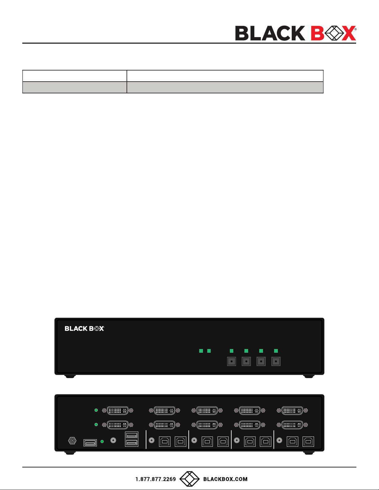
Figure 1-1: KVS4-2004DX Front panel
DVI-I OUT B DVI-I IN4 B DVI-I IN3 B DVI-I IN2 B DVI-I IN1 B
CONSOLE
12VDC
K/M
DVI-I OUT A DVI-I IN4 A DVI-I IN3 A DVI-I IN2 A DVI-I IN1 A
CAC
AUDIO
K/M K/M K/M K/M
AUDIO AUDIO AUDIO AUDIO
CAC CAC CAC CAC
IN-1IN-2IN-3IN-4
Figure 1-2: KVS4-2004DX Rear panel
4
Page 5

USER GUIDE
INSTALLATION
SYSTEM REQUIREMENTS
1. Black Box Secure PSS is compatible with standard personal/portable computers, servers or thin-clients, running
operating systems such as Windows® or Linux.
2. The peripheral devices that are supported by the Secure KVM Switch are listed in the following table:
Console Port Authorized Devices
Keyboard
Display
Audio out Analog amplied speakers, Analog headphones.
Mouse / Pointing Device Any wired mouse or trackball without internal USB hub or composite device functions.
User Authentication Device
*X - Models with CAC only Table 1-1
Wired keyboard and keypad without internal USB hub or composite device functions, unless
the connected device has at least one endpoint which is a keyboard or mouse HID class.
Display device (e.g. monitor, projector) that uses an interface that is physically and logically
compatible with the product ports (DVI-I).
USB devices identied as user authentication (base class 0Bh, e.g. Smart-card reader, PIV/
CAC reader, Token, or Biometric reader)*
5
Page 6
USER GUIDE
INSTALLATION
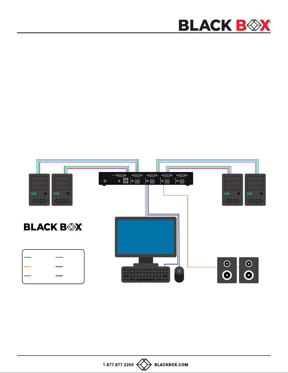
Single-Head Units:
1. Ensure that power is turned off or disconnected from the unit and the computers.
2. Use a DVI cable to connect the DVI output port from each computer to the corresponding DVI-I IN ports of the unit.
3. Use a USB cable (Type-A to Type-B) to connect a USB port on each computer to the respective USB ports of the unit.
4. Optionally connect a stereo audio cable (3.5mm to 3.5mm) to connect the audio output of the computers to the
AUDIO IN ports of the unit.
5. Connect a monitor to the DVI-I OUT console port of the unit using a DVI cable.
6. Connect a USB keyboard and mouse in the two USB console ports.
7. Optionally connect stereo speakers to the AUDIO OUT port of the unit.
8. For models with CAC, optionally connect CAC (COMMON ACCESS CARD, SMART CARD READER) to the CAC port in
the user console interface.
9. Finally, power on the Secure KVM Switch by connecting a 12VDC power supply to the power connector, and then
turn on all the computers.
Note: The computer connected to port 1 will always be selected by default after power up.
Note: You can connect up to 2 computers to the 2-port Secure KVM Switch and up to 4 computers to the 4-port
Secure KVM Switch.
CONSOLE
12VDC
K/M
AUDIO
K/M K/M K/M K/M
AUDIO AUDIO AUDIO AUDIO
KVS4-1004D
DVI-I IN
AUDIO OUT
DVI-I OUT
IMPORTANT WARNINGS - FOR SECURITY REASONS:
USB IN
USB OUT
AUDIO IN
Figure 1-3: KVS4-1004D
DVI-IDVI-IDVI-IDVI-IDVI-I OUT
IN-1IN-2IN-3IN-4
• This product does not support wireless devices. Do not attempt to use a wireless keyboard or a wireless mouse with
this product.
• This product does not support keyboards with integrated USB hubs or USB ports. Only use standard (HID) USB
keyboards with this device.
• This product does not support microphone audio input or line input. Do not connect any microphones or headsets
with microphones to this device.
• Connection of authentication devices (CAC) with external power sources is prohibited.
6
Page 7
USER GUIDE
PC Workstation
INSTALLATION (Continued)
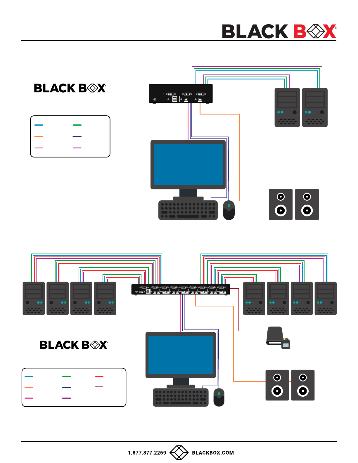
Multi-Head Units:
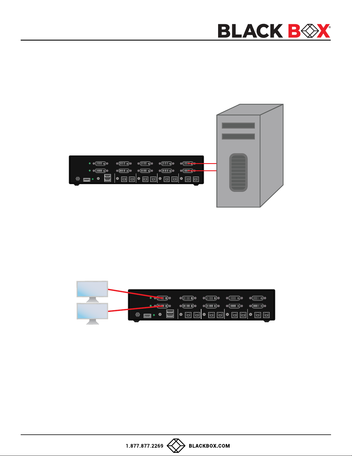
1. Ensure that power is turned off or disconnected from the unit and the computers.
2. Use DVI cables to connect the DVI output ports of each computer to the corresponding DVI-I IN ports of the unit.
For example, if using KVS4-2004DX the four DVI ports of one computer must all be connected to one channel.
DVI-I OUT B DVI-I IN4 B DVI-I IN3 B DVI-I IN2 B DVI-I IN1 B
CONSOLE
12VDC
CAC
K/M
DVI-I OUT A DVI-I IN4 A DVI-I IN3 A DVI-I IN2 A DVI-I IN1 A
AUDIO
K/M K/M K/M K/M
CAC CAC CAC CAC
AUDIO AUDIO AUDIO AUDIO
IN-1IN-2IN-3IN-4
Figure 1-4: KVS4-2004DX
The DVI-I IN connectors that belong to the same channel are arranged vertically.
3. Use a USB cable (Type-A to Type-B) to connect a USB port on each computer to the respective USB ports of the unit.
4. Optionally connect a stereo audio cable (3.5mm on both ends) to connect the audio output of the computer to the
AUDIO IN ports of the unit.
5. Connect the monitors to the DVI-I OUT console ports of the unit using DVI cables.
DVI-I OUT B DVI-I IN4 B DVI-I IN3 B DVI-I IN2 B DVI-I IN1 B
CONSOLE
12VDC
CAC
K/M
DVI-I OUT A DVI-I IN4 A DVI-I IN3 A DVI-I IN2 A DVI-I IN1 A
AUDIO
K/M K/M K/M K/M
CAC CAC CAC CAC
AUDIO AUDIO AUDIO AUDIO
IN-1IN-2IN-3IN-4
Figure 1-5: KVS4-2004DX
The DVI-I IN ports on one row will be switched to the DVI-I OUT of the same row.
6. Connect a USB keyboard and mouse in the two USB console ports.
7. Optionally connect stereo speakers to the AUDIO OUT port of the unit.
8. Optionally connect CAC (smart card reader) to the CAC port in the user console interface.
9. Power on the Secure KVM Switch by connecting a 12VDC power supply to the power connector, and then turn on all
the computers.
Note: VGA-to-DVI adapter must be used if video input sources are analog. Also, if the monitors connected to the outputs
are dual-link DVI monitors, then DVI-I cables must be used from each computer.
Note: The computer connected to port 1 will always be selected by default after power up.
7
Page 8
USER GUIDE
DVI-I IN
AUDIO OUT
DVI-I OUT
USB IN
USB OUT
AUDIO IN
CAC IN
CAC OUT
KVS4-1008DX
CACK/M
AUDIO
CACK/M
AUDIO
CACK/M
AUDIO
CACK/M
AUDIO
CACK/M
AUDIO
CACK/M
AUDIO
CACK/M
AUDIO
CACK/M
AUDIOAUDIO
DVI IN1DVI IN2DVI IN3DVI IN4DVI IN5DVI IN6DVI IN7DVI IN8DVI OUT
K/M
CAC
12VDC
CONSOLE
IN-1IN-2IN-3IN-4IN-5IN-6IN-7IN-8
INSTALLATION (Continued)
KVS4-1002D
CONSOLE
12VDC
DVI OUT DVI IN2 DVI IN1
K/M
IN-2 IN-1
K/M
AUDIO
AUDIOAUDIO
K/M
DVI-I IN
AUDIO OUT
DVI-I OUT
USB IN
USB OUT
AUDIO IN
Figure 1-6: KVS4-1002D
Figure 1-7: KVS4-1008DX
8
Page 9

USER GUIDE
INSTALLATION (Continued)
EDID Learn:
The Secure KVM Switch is designed to learn the connected monitor’s EDID upon power up. In the event of connecting a new monitor
to the Secure KVM Switch, a power recycle is required.
The Secure KVM Switch will indicate to the user the EDID learn process by ashing the front panel’s LEDs. Port one green and push
button blue LEDs will both begin to ash for about 10 seconds. When the LEDs stop ashing, the EDID learn process is done.
If the Secure KVM Switch has more than one video board (such as dual-head and quad-head models), then the unit will continue to
learn the EDIDs of the connected monitors and indicate the progress of the process by ashing the next port selection green and
push button blue LEDs respectively.
The monitor must be connected to the video output connector located in the console space at the back of the Secure KVM Switch
during the EDID learn process.
If the read EDID from the connected monitor is identical to the current stored EDID in the Secure KVM Switch then the EDID learn
function will be skipped.
9
Page 10
USER GUIDE
CAC (COMMON ACCESS CARD, SMART CARD READER) INSTALLATION
INSTALLATION
The following steps are intended for the system administrator or IT manager only.
If you have the optional CAC ports there will be 2 ports on a 2-host-port Secure KVM Switch and 4 ports on a 4-host-port
Secure KVM Switch. CAC connection to the computer requires a USB cable connection separate from the keyboard and
mouse. This allows the CAC to be connected independently from the keyboard and mouse. It also allows the user to select
whether CAC for a certain computer is supported or not.
1. Ensure that power is turned off or disconnected from the unit and the computer.
2. Use a USB cable (Type-A to Type-B) to connect a USB port on a computer to its respective CAC USB ports on
the Secure KVM Switch. Do not connect the USB cable if CAC functionality is not needed for that computer.
3. Connect a CAC (smart card reader) to the CAC port in the user console interface.
4. Power on the Secure KVM Switch by connecting a 12VDC power supply to the power connector, and then turn on all
the computers.
5. To disable CAC for any channel (all CAC ports are enabled as default), use the front panel buttons to switch the Secure
KVM Switch to the channel whose CAC mode you wish to change. Once the channel is selected, the button LED for this
specic channel should be on (CAC port enabled). Press and hold the button for 3 seconds until the button LED
turns off. The CAC port is now disabled for this channel.
To enable CAC for any channel, use the front panel buttons to switch the Secure KVM Switch to the channel whose CAC
mode you wish to change. Once the channel is selected, the button LED for this specic channel should be off
(CAC port disabled). Press and hold the button for 3 seconds until the button LED turns on. The CAC port is now enabled
for this channel. An active session on a computer is terminated upon removal of the CAC device.
Note: The open session will be immediately terminated upon the removal of the registered CAC device.
CAC PORT CONFIGURATION
The following steps are intended for the system administrator and operators (users).
Note: Only one computer connected to port 1 is required for this operation.
CAC port Conguration is an optional feature, allowing registration of any USB peripheral to operate with the
Secure KVM Switch. Only one peripheral can be registered and only the registered peripheral will operate with the Secure
KVM Switch. By default, when no peripheral is registered, the Secure KVM Switch will operate with any Smart Card Reader.
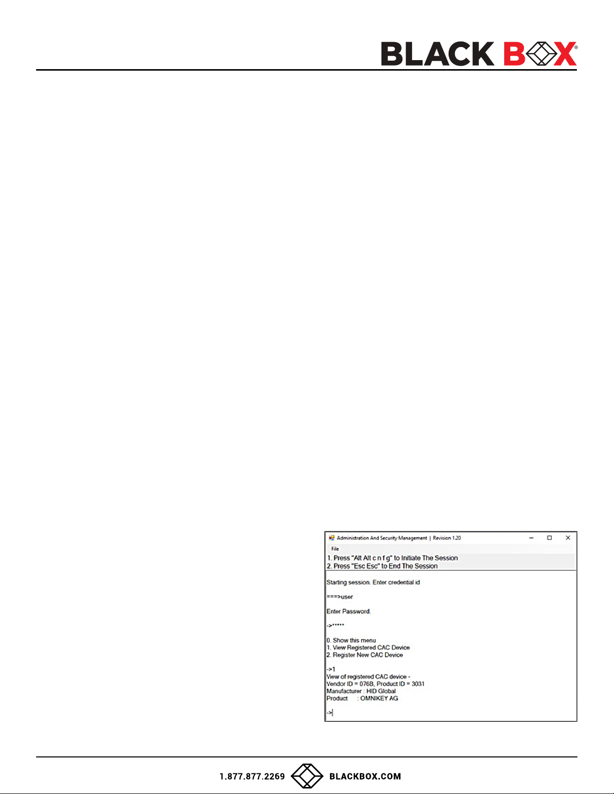
Congure the CAC Port via User Menu Options
1. Open the Administration and Security Management Program.
2. Using the keyboard, press the Alt key twice and type “cnfg”.
3. At this stage the mouse connected to the
Secure KVM Switch will stop functioning.
4. Enter the default username “user” and press Enter.
5. Enter the default password “12345” and press Enter.
6. Select "Register New CAC Device" from the menu
on your screen and press Enter.
7. Connect the peripheral device to be registered to
the CAC USB port in the console side of the
Secure KVM Switch and wait until
the Secure KVM Switch is reading the new
peripheral information.
8. The Secure KVM Switch will list the information of
the connected peripheral on the screen and buzz 3 times
when registration is completed.
Figure 1-8
10
Page 11
USER GUIDE
AUDITING: Dumping the Event Log via User Menu Options
The following steps are intended for the system administrator.
Note: Only one computer connected to port 1 is required for this operation.
The Event Log is a detailed report of critical activities stored in the Secure KVM Switch or Secure KVM Switch memory.
A comprehensive feature list and guidance for Administration and Security Management Tools can be found in the
Administrator’s Guide available for download from: https://www.blackbox.com/NIAP4/documentation
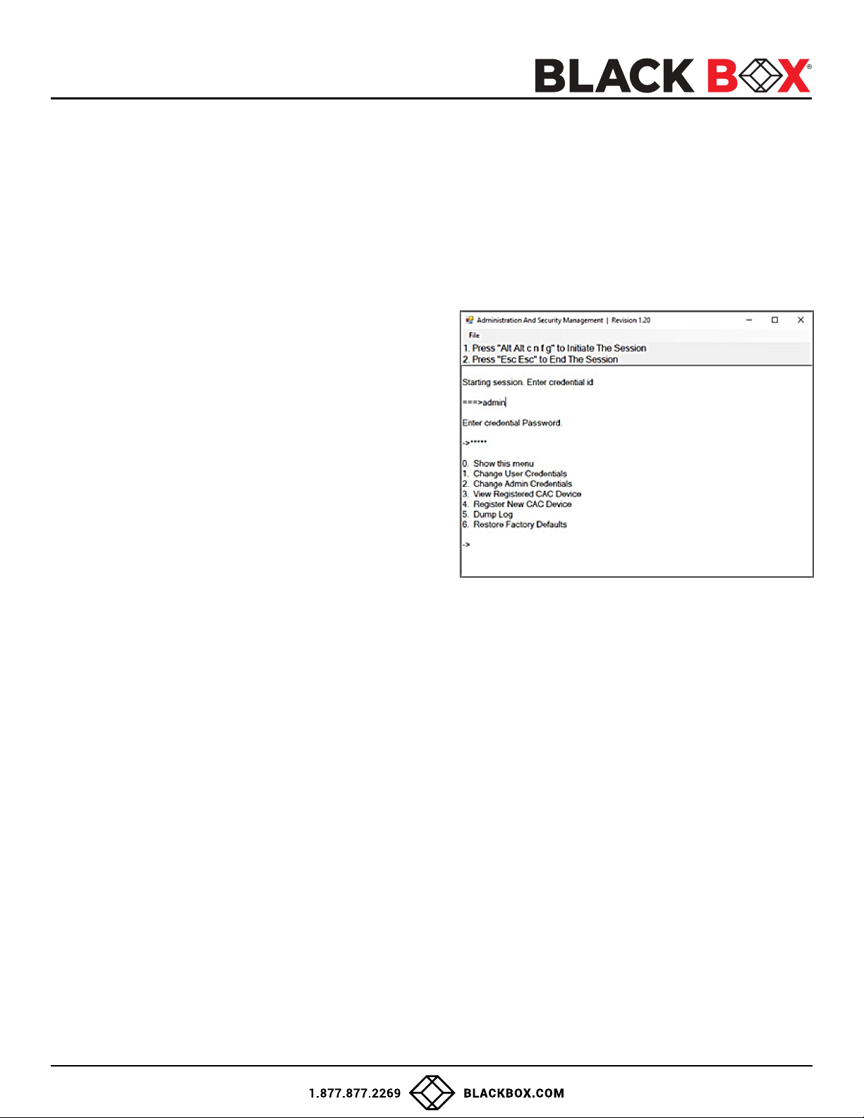
To view or dump the Event Log:
1. Open the Administration and Security Management Program.
2. Using the keyboard, press the Alt key twice and type “cnfg”.
3. Enter the default admin name “admin” and press Enter.
4. Enter the default password “12345” and press Enter.
5. Request a Log Dump by selecting "Dump Log" from the menu.
(Shown in Figure 1-9)
* See Administration and Security Management Tool Guidance
for detailed information.
Figure 1-9
RESET: Restore Factory Defaults
The following steps are intended for the system administrator.
Note: Only one computer connected to port 1 is required for this operation.
Restore Factory Defaults will reset all settings on the Secure KVM Switch to their original state.
Secure KVM Switch mode.
CAC port registration will be removed.
Secure KVM Switch settings will be reset to factory defaults.
To Restore Factory Defaults via User Menu Options:
1. Open the Administration and Security Management Program.
2. Using the keyboard, press the Alt key twice and type “cnfg”.
3. Enter the default admin name “admin” and press Enter.
4. Enter the default password “12345” and press Enter.
5. Select "Restore Factory Defaults" from the menu on your screen and press enter.
(Menu shown in Figure 1-9)
* See Administration and Security Management Tool Guidance for detailed information.
11
Page 12
USER GUIDE
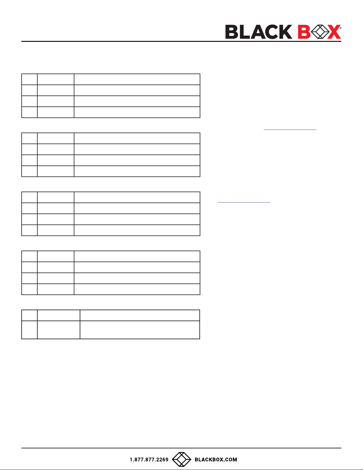
LED’s BEHAVIOR
User Console Interface – Display LED:
# Status Description
1 Off Monitor is not connected
2 On Monitor is connected
3 Flashing EDID problem – Learn EDID to x the problem
User Console Interface – CAC LED:
# Status Description
1 Off CAC is not connected
2 On Authorized and functional CAC is connected
3 Flashing Non-CAC peripheral is connected
Front Panel – Port Selection LEDs:
# Status Description
1 Off Non-selected port
2 On Selected port
3 Flashing EDID learn in process
Front Panel – CAC Selection LEDs:
IMPORTANT!
If all the Front Panel LEDs are ashing and the
buzzer is beeping, the Secure KVM Switch has
been TAMPERED with and all functions are
permanently disabled. Please contact Black Box
technical support at [email protected]
If all Front Panel LEDs are on and not ashing, the
POWER UP SELF TEST has failed and all functions
are disabled. Check if any of the front panel
port selection buttons are jammed. In this case,
release the jammed button and recycle the power.
If power up self test is still failing, please contact
Black Box technical support
at [email protected]
# Status Description
1 Off CAC port is disabled or non-selected port
2 On CAC port is enabled
3 Flashing EDID learn in process
Front Panel - Port and CAC Selection LEDs:
# Status Description
1 All Flashing
EDID Learn - Front Panel LEDs:
All LEDs are turned on for 1 second. Then:
• Port 1 LEDs will ash until the end of the process.
• Port 2 LEDs will ash until the end of the process if a second video board exists (Dual-head Secure KVM Switch).
• Port 3 LEDs will ash until the end of the process if a third video board exists (Quad-head Secure KVM Switch).
• Port 4 LEDs will ash until the end of the process if a fourth video board exists (Quad-head Secure KVM Switch).
Connected peripheral to keyboard or mouse
console ports is rejected
12
Page 13

USER GUIDE
SYSTEM OPERATION
Front Panel Control
To switch to an input port, simply push the desired input button on the front-panel of the Secure KVM Switch. If an input
port is selected, the LED of that port will turn on. An open session is terminated upon switching to a different computer.
TROUBLESHOOTING
No Power
• Make sure that the power adapter is securely connected to the power connector of the unit.
• Check the output voltage of the power supply and make sure that the voltage value is around 12VDC.
• Replace the power supply.
Flashing LEDs in the Front Panel with clicking sound
• Reboot the unit. If the error persists then there is a malfunction or wrong input connections at the K/M ports.
• Verify both Keyboard and Mouse connections are USB 1.0 or 1.1.
• Only USB Keyboard or Mouse can be connected in the designated K/M ports.
Flashing USB LED
• Make sure that the correct peripheral device is connected to the correct port of the Secure KVM.
• Check to see that the K/M USB cable is connected to the K/M port on the back of the unit.
• Check to see that the CAC USB cable is connected to the CAC port on the back of the unit.
No Video
• Check if all the video cables are connected properly.
• Connect the computer directly to the monitor to verify that your monitor and computer are functioning properly.
• Restart the computers.
Keyboard is not working
• Check if the keyboard is properly connected to the unit.
• Check if the USB cables connecting the unit and the computers are properly connected.
• Try connecting the USB on the computer to a different port.
• Make sure that the keyboard works when directly connected to the computer.
• Replace the keyboard.
Note: The NUM, CAPS, and SCROLL Lock LED indicators on the keyboard are not supposed to light up if connected to the
Secure KVM Switch.
Mouse is not working
• Check if the mouse is properly connected to the unit.
• Try connecting the USB on the computer to a different port.
• Make sure that the mouse works when directly connected to the computer.
• Replace the mouse.
No Audio
• Check if all the audio cables are connected properly.
• Connect the speakers directly to the computer to verify that the speakers and the computer audio are
functioning properly.
• Check the audio settings of the computer and verify that the audio output is through the speakers.
No CAC (COMMON ACCESS CARD, SMART CARD READER)
• Check if the USB cables connecting the unit and the computers are properly connected.
• Make sure the CAC port is enabled by holding down the desired channels button until it lights up.
TECHNICAL SUPPORT
For product inquiries, warranty questions, or technical questions, please contact [email protected].
FREE technical support 24 hours a day, 7 days a week: Call 877-877-2269 or fax 724-746-0746.
13
Page 14

USER GUIDE
LIMITED WARRANTY STATEMENT
A. Extent of limited warranty
Black Box warrants to the end-user customers that the product specied above will be free from defects in materials and
workmanship for the duration of 18 months, which duration begins on the date of purchase by the customer. Customer is
responsible for maintaining proof of date of purchase.
Black Box limited warranty covers only those defects which arise as a result of normal use of the product, and do not apply
to any:
a. Improper or inadequate maintenance or modications
b. Operations outside product specications
c. Mechanical abuse and exposure to severe conditions
If Black Box receives, during applicable warranty period, a notice of defect, Black Box will at its discretion replace or repair
defective product. If Black Box is unable to replace or repair defective product covered by the Black Box warranty within
reasonable period of time, Black Box shall refund the cost of the product.
Black Box shall have no obligation to repair, replace or refund unit until customer returns defective product to Black Box.
Any replacement product could be new or like new, provided that it has functionality at least equal to that of the product
being replaced.
Black Box limited warranty is valid in any country where the covered product is distributed by Black Box.
B. Limitations of warranty
To the extent allowed by local law, neither Black Box nor its third party suppliers make any other warranty or condition of
any kind whether expressed or implied with respect to the Black Box product, and specically disclaim implied warranties or
conditions of merchantability, satisfactory quality, and tness for a particular purpose.
C. Limitations of liability
To the extent allowed by local law the remedies provided in this warranty statement are the customers sole and exclusive
remedies.
To the extent allowed by local law, except for the obligations specically set forth in this warranty statement, in no event
will Black Box or its third party suppliers be liable for direct, indirect, special, incidental, or consequential damages whether
based on contract, tort or any other legal theory and whether advised of the possibility of such damages.
D. Local law
To the extent that this warranty statement is inconsistent with local law, this warranty statement shall be considered
modied to be consistent with such law.
14
Page 15

USER GUIDE
DISCLAIMER
Black Box Corporation shall not be liable for damages of any kind, including, but not limited to, punitive, consequential or
cost of cover damages, resulting from any errors in the product information or specications set forth in this document and
Black Box Corporation may revise this document at any time without notice.
TRADEMARKS
Black Box and the Black Box logo type and mark are registered trademarks of BB Technologies, Inc.
Any other trademarks mentioned in this document are acknowledged to be the property of the trademark owners.
© COPYRIGHT 2022. BLACK BOX CORPORATION. ALL RIGHTS RESERVED.
20180411
Black Box Corporation
1000 Park Drive
Lawrence, PA 15055-1018
Phone: 877-877-2269
KVS4-1002D_user_Rev1.pdf
N4-BB-DVI-2-4-8-KVM
www.blackbox.com
15
 Loading...