

Page 1
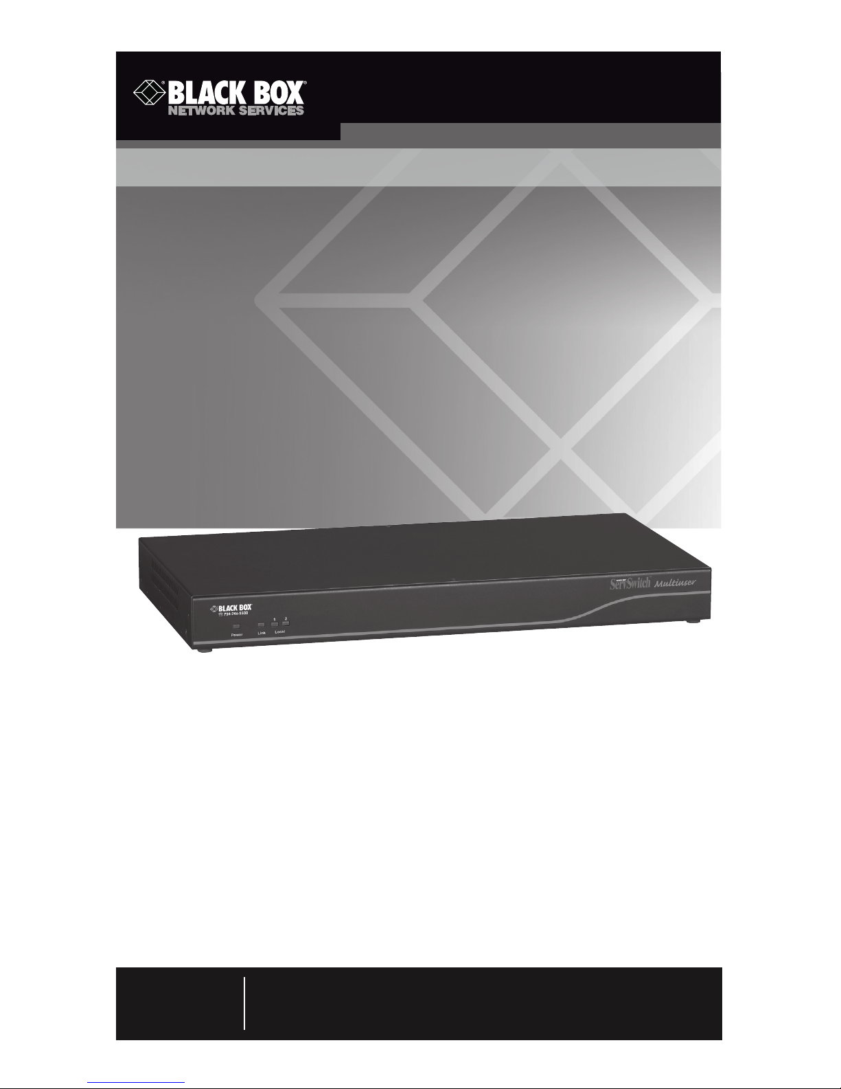
Multiuser access and control of 16 or 32
computers/servers.
This high performance KVM switch enables multiuser access, control, and
management of multiple servers. With Black Box Server Access Modules
and CAT5 cabling, clutter in your data center is eliminated. And distance
can be extended to 100 feet.
ServSwitch™ Multiuser User’s Manual
Order toll-free in the U.S.: Call 877-877-BBOX (outside U.S. call 724-746-5500)
FREE technical support 24 hours a day, 7 days a week: Call 724-746-5500 or fax
724-746-0746 • Mailing address: Black Box Corporation, 1000 Park Drive, Lawrence,
PA 15055-1018 • Web site: www.blackbox.com • E-mail: [email protected]
Customer
Support
Information
June 2010
KVM2016A
KVM2032A
Page 2

Page 3

Page 1
724-746-5500 | blackbox.com
FCC and NOM Statements
FEDERAL COMMUNICATIONS COMMISSION AND
INDUSTRY CANADA RADIO FREQUENCY INTERFERENCE STATEMENTS
This equipment generates, uses, and can radiate radio-frequency energy,
and if not installed and used properly, that is, in strict accordance with the
manufacturer’s instructions, may cause inter ference to radio communication.
It has been tested and found to comply with the limits for a Class A computing
device in accordance with the specifications in Subpart B of Part 15 of FCC rules,
which are designed to provide reasonable protection against such interference
when the equipment is operated in a commercial environment. Operation of
this equipment in a residential area is likely to cause interference, in which case
the user at his own expense will be required to take whatever measures may be
necessary to correct the interference.
Changes or modifications not expressly approved by the party responsible
for compliance could void the user’s authority to operate the equipment.
This digital apparatus does not exceed the Class A limits for radio noise
emis sion from digital apparatus set out in the Radio Interference Regulation
of Industry Canada.
Le présent appareil numérique n’émet pas de bruits radioélectriques dépassant
les limites applicables aux appareils numériques de la classe A prescrites dans le
Règlement sur le brouillage radioélectrique publié par Industrie Canada.
Normas Oficiales Mexicanas (NOM)
Electrical Safety Statement
INSTRUCCIONES DE SEGURIDAD
1. Todas las instrucciones de seguridad y operación deberán ser leídas antes
de que el aparato eléctrico sea operado.
2. Las instrucciones de seguridad y operación deberán ser guardadas para
referencia futura.
3. Todas las advertencias en el aparato eléctrico y en sus instrucciones de
operación deben ser respetadas.
4. Todas las instrucciones de operación y uso deben ser seguidas.
Page 4

Page 2
724-746-5500 | blackbox.com
ServSwitch Multiuser
5. El aparato eléctrico no deberá ser usado cerca del agua—por ejemplo,
cerca de la tina de baño, lavabo, sótano mojado o cerca de una alberca,
etc..
6. El aparato eléctrico debe ser usado únicamente con carritos o pedestales
que sean recomendados por el fabricante.
7. El aparato eléctrico debe ser montado a la pared o al techo sólo como sea
recomendado por el fabricante.
8. Servicio—El usuario no debe intentar dar servicio al equipo eléctrico más allá
lo descrito en las instrucciones de operación. Todo otro servicio deberá ser
referido a personal de servicio calificado.
9. El aparato eléctrico debe ser situado de tal manera que su posición no
interfiera su uso. La colocación del aparato eléctrico sobre una cama, sofá,
alfombra o superficie similar puede bloquea la ventilación, no se debe
colocar en libreros o gabinetes que impidan el flujo de aire por los orificios
de ventilación.
10. El equipo eléctrico deber ser situado fuera del alcance de fuentes de calor
como radiadores, registros de calor, estufas u otros aparatos (incluyendo
amplificadores) que producen calor.
11. El aparato eléctrico deberá ser connectado a una fuente de poder sólo del
tipo descrito en el instructivo de operación, o como se indique en el
aparato.
12. Precaución debe ser tomada de tal manera que la tierra fisica y la
polarización del equipo no sea eliminada.
13. Los cables de la fuente de poder deben ser guiados de tal manera que no
sean pisados ni pellizcados por objetos colocados sobre o contra ellos,
poniendo particular atención a los contactos y receptáculos donde salen
del aparato.
14. El equipo eléctrico debe ser limpiado únicamente de acuerdo a las
recomendaciones del fabricante.
15. En caso de existir, una antena externa deberá ser localizada lejos de las
lineas de energia.
16. El cable de corriente deberá ser desconectado del cuando el equipo no sea
usado por un largo periodo de tiempo.
Page 5

Page 3
724-746-5500 | blackbox.com
NOM Statement/WEEE Compliance
17. Cuidado debe ser tomado de tal manera que objectos liquidos no sean
derramados sobre la cubierta u orificios de ventilación.
18. Servicio por personal calificado deberá ser provisto cuando:
A: El cable de poder o el contacto ha sido dañado; u
B: Objectos han caído o líquido ha sido derramado dentro del aparato; o
C: El aparato ha sido expuesto a la lluvia; o
D: El aparato parece no operar normalmente o muestra un cambio en su
desempeño; o
E: El aparato ha sido tirado o su cubierta ha sido dañada.
WEEE Compliance
Page 6

Page 4
724-746-5500 | blackbox.com
ServSwitch Multiuser
TRADEMARKS USED IN THIS MANUAL
Black Box and the Double Diamond logo are registered trademarks, and
ServSwitch is a trademark, of BB Technologies, Inc.
Linux is a registered trademark of Linus Torvalds.
Windows is a registered trademark of Microsoft Corporation.
Novell is a registered trademark of Novell, Inc.
Solaris and Sun are registered trademarks of Sun Microsystems, Inc.
Any other trademarks mentioned in this manual are acknowledged to be
the property of the trademark owners.
Page 7

Page 5
724-746-5500 | blackbox.com
Table of Contents
Table of Contents
1. Specifications .................................................................................................... 7
2. Overview ..........................................................................................................8
2.1 Introduction ............................................................................................ 8
2.2 Front Panel .............................................................................................8
2.3 Back Panel ..............................................................................................9
2.4 What’s Included ....................................................................................10
2.5 Features ................................................................................................10
2.6 Compatibility ........................................................................................10
3. Pre-Installation Guidelines ...............................................................................11
3.1 Avoiding General Rackmounting Problems ...........................................11
3.2 Rackmounting the ServSwitch ..............................................................11
4. Connecting the System ...................................................................................13
4.1 The SAMs .............................................................................................13
4.1.1 Connecting an SAM PS/2 ............................................................14
4.1.2 Connecting an SAM USB .............................................................15
4.2 Connecting the CAT5 Cables ................................................................16
4.3 Connecting the Two KVM Consoles ......................................................16
4.4 Connecting to the Power Supply ..........................................................16
5. Configuring the System ..................................................................................17
5.1 Connecting the Local Area Network (LAN) ............................................17
5.2 Setting Network Parameters via the OSD ...............................................17
5.3 Changing the Network Parameters .......................................................18
6. Web Configuration .........................................................................................19
7. Network Configuration ................................................................................... 21
7.1 Network > Configuration ...................................................................... 21
7.2 Administration > User Settings ..............................................................22
7.2.1 Adding a User ..............................................................................23
7.2.2 Deleting a User ............................................................................23
7.2.3 Blocking a User ............................................................................23
7.3 Administration > Switch Configuration .................................................24
7.4 Administration > Power Management ...................................................25
8. Administration > User Targets .........................................................................26
9. Security > Settings ..........................................................................................27
Page 8

Page 6
724-746-5500 | blackbox.com
ServSwitch Multiuser
10. Security > SSL Certificate ................................................................................29
11. Maintenance > Switch Upgrade ......................................................................30
12. Maintenance > SAMs Upgrade .......................................................................31
13. Restore Factory Settings ..................................................................................32
14. Set Time & Date... ...........................................................................................33
15. Backup and Restore ........................................................................................ 34
16. Saving Changes and Logging Out ...................................................................35
17. Event Log .......................................................................................................36
17.1 Downloading the Log............................................................................36
17.2 Clearing the Log ...................................................................................36
18. Operating the System via the OSD ..................................................................37
18.1 Navigating the OSB Main Window ........................................................37
18.2 Selecting a Computer ............................................................................37
18.3 Power Management Hotkey ..................................................................37
18.4 Moving the Confirmation Label .............................................................39
18.5 Tuning ...................................................................................................39
18.6 The Settings Window ............................................................................40
18.7 DDC ......................................................................................................41
18.8 Saving Changes to the Settings .............................................................41
19. Troubleshooting ..............................................................................................42
19.1 Calling Black Box ...................................................................................42
19.2 Shipping and Packaging ........................................................................42
Appendix. Remote Power Switching ......................................................................43
Page 9

Page 7
724-746-5500 | blackbox.com
Chapter 1: Specifications
1. Specifications
Distance from Switch to SAMs: Up to 100 ft. (30 m)
Resolution: Up to 1600 x 12000 @ 85 Hz
Server Operating Systems: Windows®, Novell®, Linux®, Sun® Solaris
®
System Cable: CAT5 UTP/FTP solid wire 24 AWG
Connectors: Ethernet: (1) RJ-45, 10/100 Mbps autosensing
RPS: (1) RJ-45;
KVM: (2) HDD15 for monitors, (2) USB for keyboard and mouse;
Servers: KVM2016A: (16) RJ-45,
KVM2032A: (32) RJ-45;
KV1120A: VGA: (1) HDD15;
Keyboard/Mouse: (1) 6-pin mini-DIN;
System: (1) RJ-45;
KV1121A: VGA: (1) HDD15;
Keyboard/Mouse: (1) USB;
System: (1) RJ-45
Temperature Tolerance: Operating: 32 to 104° F (0 to 40° C);
Storage: -40 to +158° F (-40 to +70° C)
Relative Humidity: 80%, noncondensing
Power: Input: KVM2016A, KVM2032A: 120–240 VAC. 0.8 A, 50/60 Hz;
KV1120A: from keyboard port;
KV1121A: from USB port
Size: KVM2016A: 1.7"H x 17"W x 10"D (4.4 x 43.1 x 2.7 cm);
KVM2032A: 1.7"H x 17"W x 10"D (4.4 x 43.1 x 2.7 cm);
KV1120A, KV1121A: 0.21"H x 0.08"W x 0.08"D (0.53 x 0.2 x 0.2 cm)
Weight: KVM2016A: 5.2 lb. (2.3 kg);
KVM2032A: 5.2 lb. (2.3 kg);
KV1120A, KV1121A: 0.2 lb. (0.1 kg)
Shipping Weight: KV1120A, KV1121A: 0.38 lb. (0.17 kg)
Page 10

Page 8
724-746-5500 | blackbox.com
ServSwitch Multiuser
2. Overview
2.1 Introduction
The ServSwitch Multiuser 2 Users x 16 Ports (KVM2016A) or the ServSwitch
Multiuser 2 Users x 32 Ports (KVM2032A) extends your KVM (keyboard, video,
and mouse) from servers with PS/2 or USB interfaces up to 100 feet (30 m) away.
Two users can control, monitor, and manage up to 16 or 32 servers simultaneously. You can connect a power distribution unit (PDU) for power management.
The KVM2016A and KVM2032A are functionally the same, except the
KVM2016A connects to 16 servers and the KVM2032A links to 32 servers.
The ServSwitch units provide secure KVM access and control for up to 16 or 32
computers/servers from the BIOS level—and they are independent of the operating system.
With innovative SAM technology, the computer/server connects directly to the
switch via SAM dongles using only standard CAT5 cable at a distance up to 100
feet (30 m) in a star configuration. No external power is required at the SAM.
2.2 Front Panel
Figure 2-1 shows the KVM2016A and KVM2032A front panels and Table 2-1
describes their components.
Power Link
12
Local
1
2
3
Figure 2-1. KVM2016A or KVM2032A’s front panel.
Table 2-1. Front panel components.
Number Component Description
1 Power LED Lights when unit is powered on
2 Link LED Lights when the unit is connected to the net-
work
3 Local LEDs Lights when the corresponding user is
administrating a target.
1 and 2
Page 11
Page 9
724-746-5500 | blackbox.com
Chapter 2: Overview
2.3 Back Panel
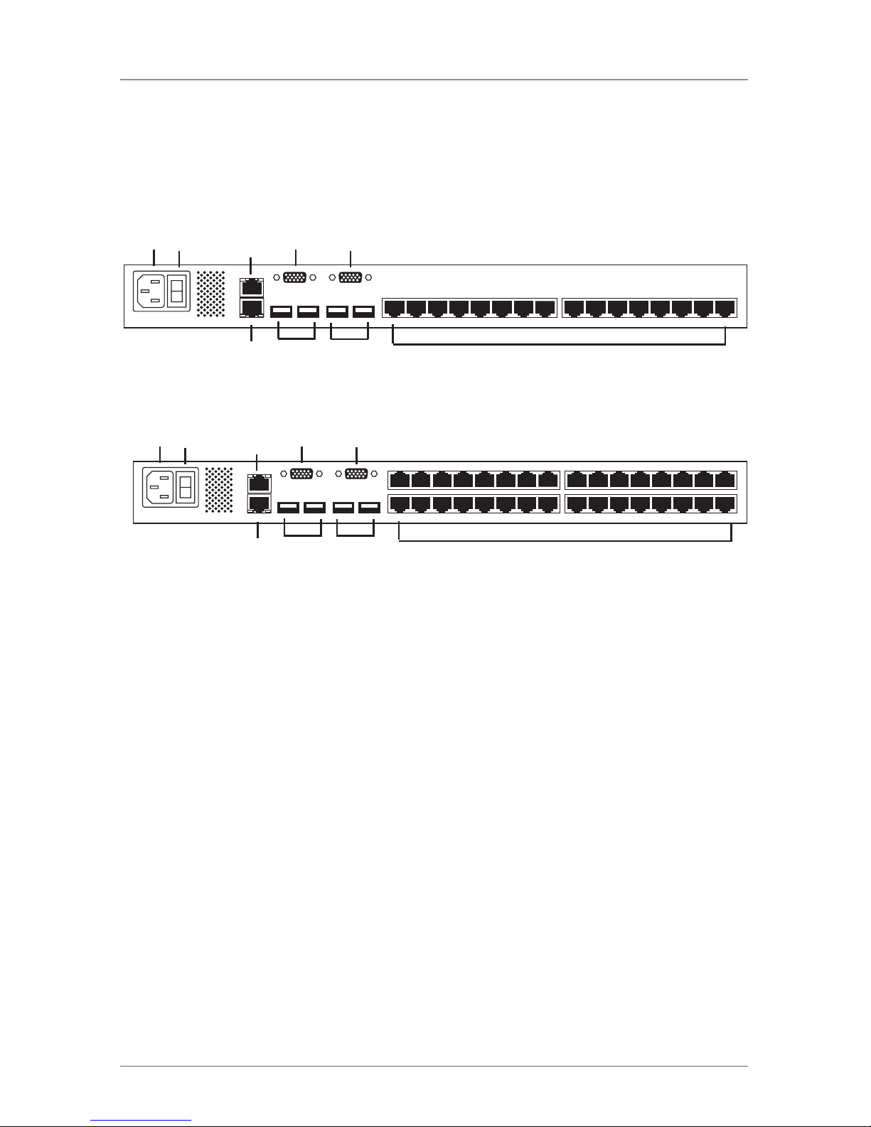
Figures 2-3 and 2-4 illlustrate the KVM2016A and KVM2032A back panels and
Table 2-2 describes their components.
9 10
4
4
5
5
7
6
8
Figure 2-3. KVM2016A’s back panel.
9 10
4
4
5
5
7
6
8
Figure 2-4. KVM2032A’s back panel.
Table 2-2. Back panel components.
Number Component Description
4 User 1 and User 2 Connect monitors for
HD15 connectors (2) users to operate the ServSwitch.
5 User 1 and User 2 Connect keyboards and mice for
USB Type A connectors (2) users to operate the ServSwitch.
6 RJ-45 connector Serial remote power switch port
RPS port (reserved for future use).
7 RJ-45 connector Connect to 10/100 Mbps Ethernet to
for Config port configure and update the unit.
8 (16) or (32) RJ-45 Link to servers via SAMs.
server ports
9 Power connector Connect 120 VAC power.
10 I/O power switch Turns power on or off.
Page 12

Page 10
724-746-5500 | blackbox.com
ServSwitch Multiuser
2.4 What’s Included
Your package should include the following items. If anything is missing or damaged, please contact Black Box Technical Support at 724-746-5500.
• KVM2016A or KVM2032A
• Rackmounting kit
• Power cord
• A printed Quick Start Guide
• This User’s Manual on CD-ROM
2.5 Features
The ServSwitch Multiuser is compatible with all major operating systems. It supports advanced OSD management with multi-layer security for local users. Plus,
the ServSwitch features seamless power control.
2.6 Compatibility
The ServSwitch Multiuser works with:
• PS/2 or USB interface computers/servers
• VGA, SVGA, or XGA monitors (UXGA and higher)
• Windows, Linux, and other major operating systems
Page 13

Page 11
724-746-5500 | blackbox.com
Chapter 3: Pre-Installation Guidelines
3. Pre-Installation Guidelines
• Place cables away from fluorescent lights, air conditioners, and machines that
are likely to generate electric noise.
• Place the ServSwitch Multiuser on a flat, clean, and dry surface or install it in a
rack.
• Make sure that the maximum distance between each computer and the
ServSwitch doesn’t exceed 100 feet (30 m).
3.1 Avoiding General Rackmount Problems
Elevated operating ambient temperature:
The rack environment’s operating ambient temperature may be greater than the
room ambient temperature when installing it into a closed or multi-unit rack
assembly. Install the equipment in an environment that’s compatible with the
maximum rated ambient temperature.
Reduced airflow:
Install the equipment in a rack so that the amount of airflow required for safe
operation is not compromised. Leave a gap of at least 2" (5 cm) on each side of
the ServSwitch.
Mechanical loading:
Do not create a hazardous condition caused by uneven mechanical loading.
Mount the equipment in the rack safely.
Circuit overloading:
When connecting the equipment to the supply circuit, do not overload circuits.
If you do, over-current protection and supply wiring might fail.
Maintain reliable earth grounding for the rackmounted equipment. Check supply connections for power strips that are not connected directly to the branch circuit.
3.2 Rackmounting the ServSwitch
Using the included rackmount kit, rackmount the ServSwitch Multiuser unit.
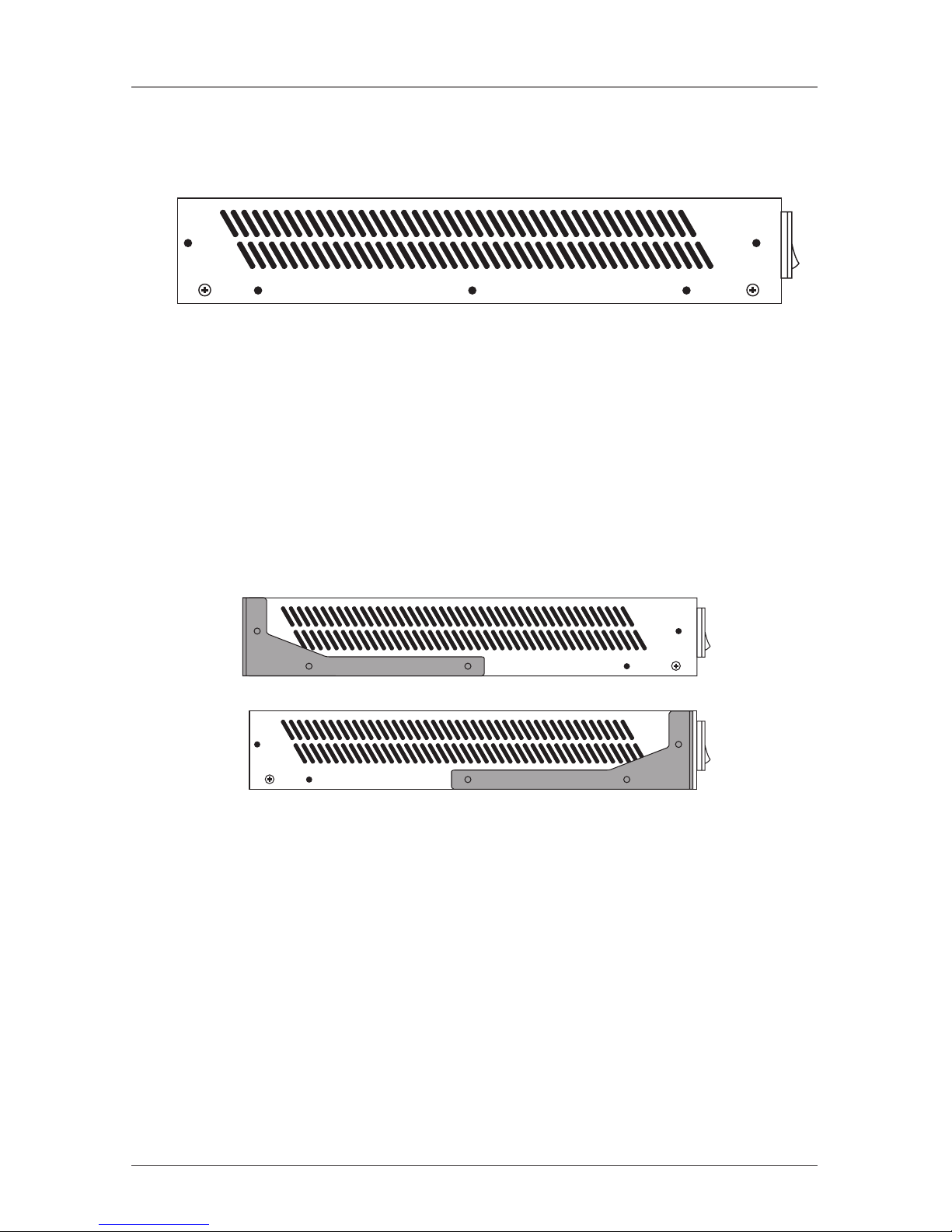
You can place the brackets in two possible positions, shown in Figure 3-1.
Page 14
Page 12
724-746-5500 | blackbox.com
ServSwitch Multiuser
Figure 3-1. Bracket positions.
Place the brackets towards the unit’s front so you can mount the unit facing the
front, or place the brackets towards the unit’s rear so you can mount the unit facing the rear. Figure 3-2 illustrates the bracket connected in the rear-facing position.
Using the included screws, screw the bracket to the ServSwitch Multiuser.
Figure 3-2. Bracket connected.
Page 15
Page 13
724-746-5500 | blackbox.com
Chapter 4: Connecting the System
4. Connecting the System
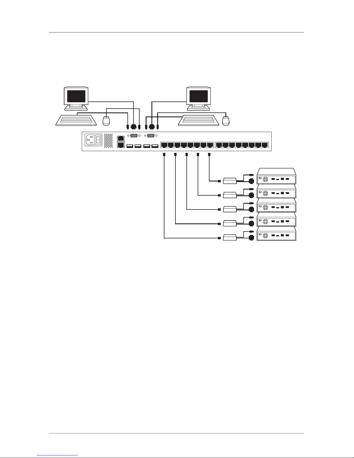
Figure 4-1 illlustrates the ServSwitch Multiuser system overview.
Keyboard, monitor,
and mouse connected
to KVM User 2 port
Keyboard, monitor,
and mouse connected
to KVM User 1 port
To servers
SAMs
Figure 4-1. ServSwitch Multiuser system overview.
4.1 The SAMs
Each computer/server is directly connected to the ServSwitch Multiuser via the
appropriate SAM using CAT5 cable in a star configuration. No external power is
needed at the SAMs. They draw their power from the computer’s keyboard port
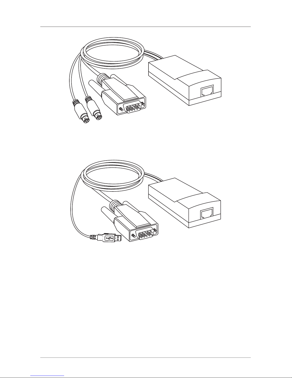
(SAM PS/2) or from the USB port (SAM USB). Figures 4-2 and 4-3 show the SAM
PS/2 and the SAM USB.
Page 16
Page 14
724-746-5500 | blackbox.com
ServSwitch Multiuser
To computer’s video
card
To computer’s
keyboard port
To computer’s
mouse port
Figure 4-2. SAM PS/2 (KV1120A).
To computer’s video
card
To computer’s USB
port
Figure 4-3. SAM USB (KV1121A).
1. Switch off the server.
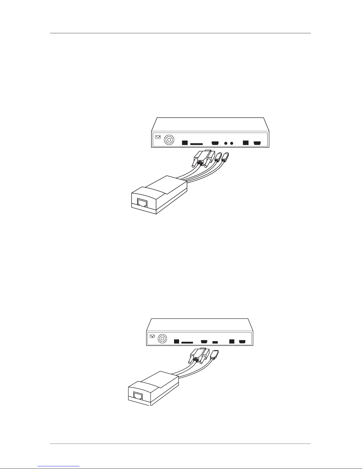
2. Connect the SAM PS/2. Figure 4-4 illustrates the SAM PS/2 connections.
3. Power on the server.
You can connect the SAM PS/2 to a powered on computer in the following
order:
1. Connect the mouse connector to the computer’s mouse port.
Page 17
Page 15
724-746-5500 | blackbox.com
Chapter 4: Connecting the System
2. Connect the keyboard connector to the computer’s keyboard port.
3. Connect the screen connector to the computer’s video port.
If you don’t follow the order listed above when connecting while the server is
running, the mouse may not function correctly until you reboot the server.
CAT5 cable
to switch
server port
To video port
To keyboard
and mouse
ports
Figure 4-4. SAM PS/2 connections (KV1120A).
4.1.2 Connecting a SAM USB
The SAM USB supports Windows 98 SE and later, MAC, SUN, and SGI, and all
modern Linux distributions. Figure 4-5 shows the SAM USB and its connections.
To connect the SAM USB:
1. Connect the screen connector to the computer’s video port.
2. Connect the USB connector to the computer‘s USB port.
CAT5 cable
to switch
server port
To video port
To USB port
Figure 4-5. SAM USB (KV1121A).
Page 18

Page 16
724-746-5500 | blackbox.com
ServSwitch Multiuser
4.2 Connecting the CAT5 Cables
1. Attach one connector to the SAM’s RJ-45 port.
2. Connect the other connector to one of the ServSwitch Multiuser's ports.
3. Repeat steps 1 and 2 for each computer.
4.3 Connecting the Two KVM Consoles
Connect a keyboard, monitor, and mouse to the user 1 and user 2 ports as follows:
1. Connect the monitor connectors to the monitor ports.
2. Connect the keyboard connectors to the keyboard ports.
3. Connect the mouse connectors to the mouse ports.
4.4 Connecting to the Power Supply
1. Using the included power cord, connect the ServSwitch Multiuser to a socket
outlet that has a grounding connection. Use only the power cord you received
with the unit.
2. Switch on the unit.
Page 19
Page 17
724-746-5500 | blackbox.com
Chapter 5: Configuring the System
5. Configuring the System
Configuring the system includes assigning server names, user and security set-
tings, and maintenance.
5.1 Connecting to the Local Area Network (LAN)
Configure the unit via a web interface. Connect a network cable to the LAN
port of the ServSwitch Multiuser.
5.2 Setting Network Parameters via the OSD
By default, the ServSwitch Multiuser boots with an automatically assigned IP
address from a Dynamic Host Configuration Protocol (DHCP) server on the network. The DHCP server provides a valid IP address, gateway address, and subnet
mask.
You can identify the IP address from the OSD. Where there is no DHCP server,
set the IP address via the OSD as follows:
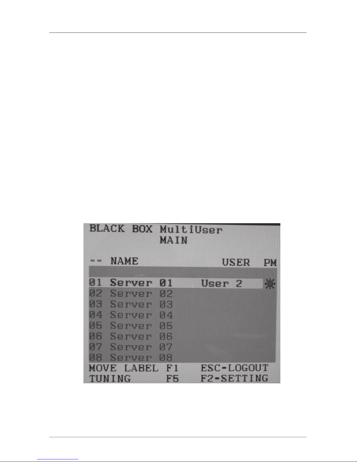
1. From the local keyboard, press left Shift twice. The OSD Main window appears.
See Figure 5-1.
Figure 5-1. Main menu.
Page 20
Page 18
724-746-5500 | blackbox.com
ServSwitch Multiuser
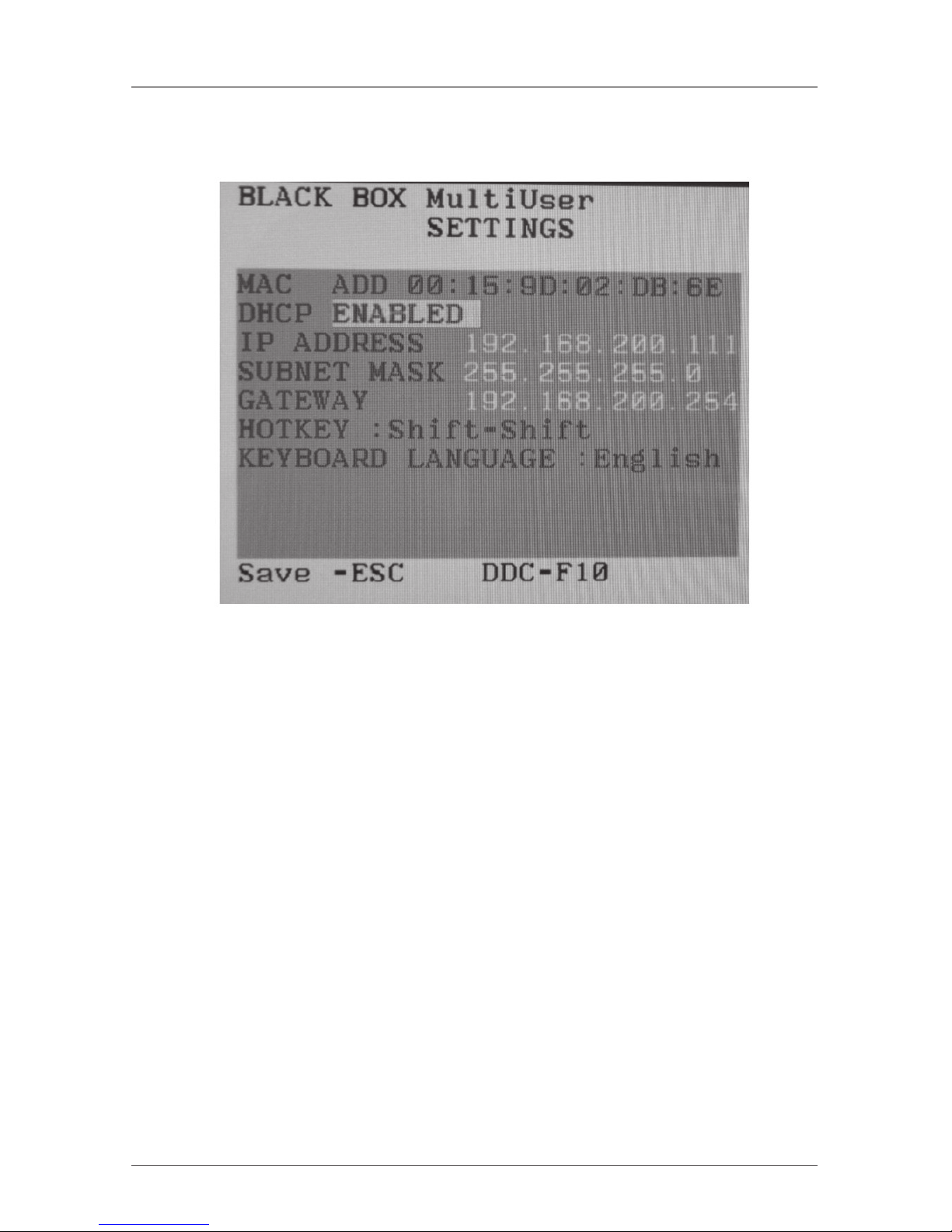
2. Press F2. The Settings window appears. See Figure 5-2.
Figure 5-2. Settings window.
Using the Tab key, navigate downwards in the Settings window. At the bottom
of the window, press the Tab key to go to the top of the window. To change settings, type in the selected area or press the spacebar.
5.3 Changing the Network Parameters
DHCP enable—When a DHCP server is active on the same network that the
ServSwitch Multiuser is connected to, DHCP provides automatic IP assignment.
This is displayed in the OSD.
DHCP disabled (recommended)—You can assign a fixed IP address to the
ServSwitch Multiuser. Consult your network administrator about using the DHCP.
When DHCP is disabled, enter the IP address, subnet mask, and gateway as
given by your network administrator.
Once the IP address is correct, press Esc twice to save changes and restart the
unit. As explained below, you can now log in to the web interface to complete
the configuraton.
Page 21
Page 19
724-746-5500 | blackbox.com
Chapter 6: Web Configuration
6. Web Configuration
1. Open your web browser.
2. Type the ServSwitch Multiuser's system IP address: http or https://IP address/ and
press Enter. The login page appears.
3. Type the default administrator user name—admin—and password—access—
(both lower case).
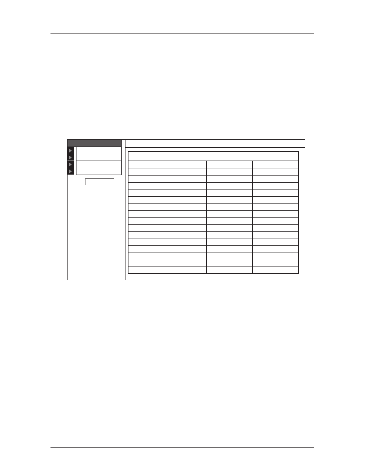
4. Press Enter. The web interface opens at the Targets page. See Figure 6-1.
Server Name Server Status
Off
On
On
On
On
On
On
Off
Off
Off
Off
Off
Off
Off
Off
Off
File Server
KVManager
Windows 2003
ESX 3i 3.5
Windows XP
Server 06
Novell SuSE
Server 08
Server 09
Server 10
Server 11
Server 12
Server 13
Server 14
Server 15
Server 16
admin: Ta rgetsNetwork
Password
No. Ta rgets
Configuration
Event Log
Logout
User
Figure 6-1. Targets page.
Columns:
Server name—You can change the server name in the configuration settings to
give the server a name you can identify.
Server status—Server status can be on, off, or busy (when a user is accessing
the server).
User—The current user (if any) accessing the server.
From the Targets page menu—see Figure 1—an administrator can:
• Change the password
• Reach the configuration pages
• See an event log (explained in Chapter 17)
Page 22
Page 20
724-746-5500 | blackbox.com
ServSwitch Multiuser
Changing the Password
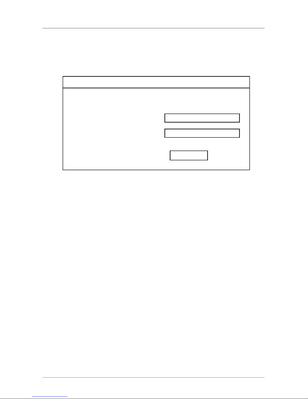
To change the password, from the menu click Password, and Figure 6-2
appears.
User Name:
Password:
Confirm Password:
admin
Apply
admin: Properties
Figure 6-2. Properties.
Type a new password according to the password policy set—see Chapter 9.
Page 23
Page 21
724-746-5500 | blackbox.com
Chapter 7: Network Configuration
7. Network Configuration
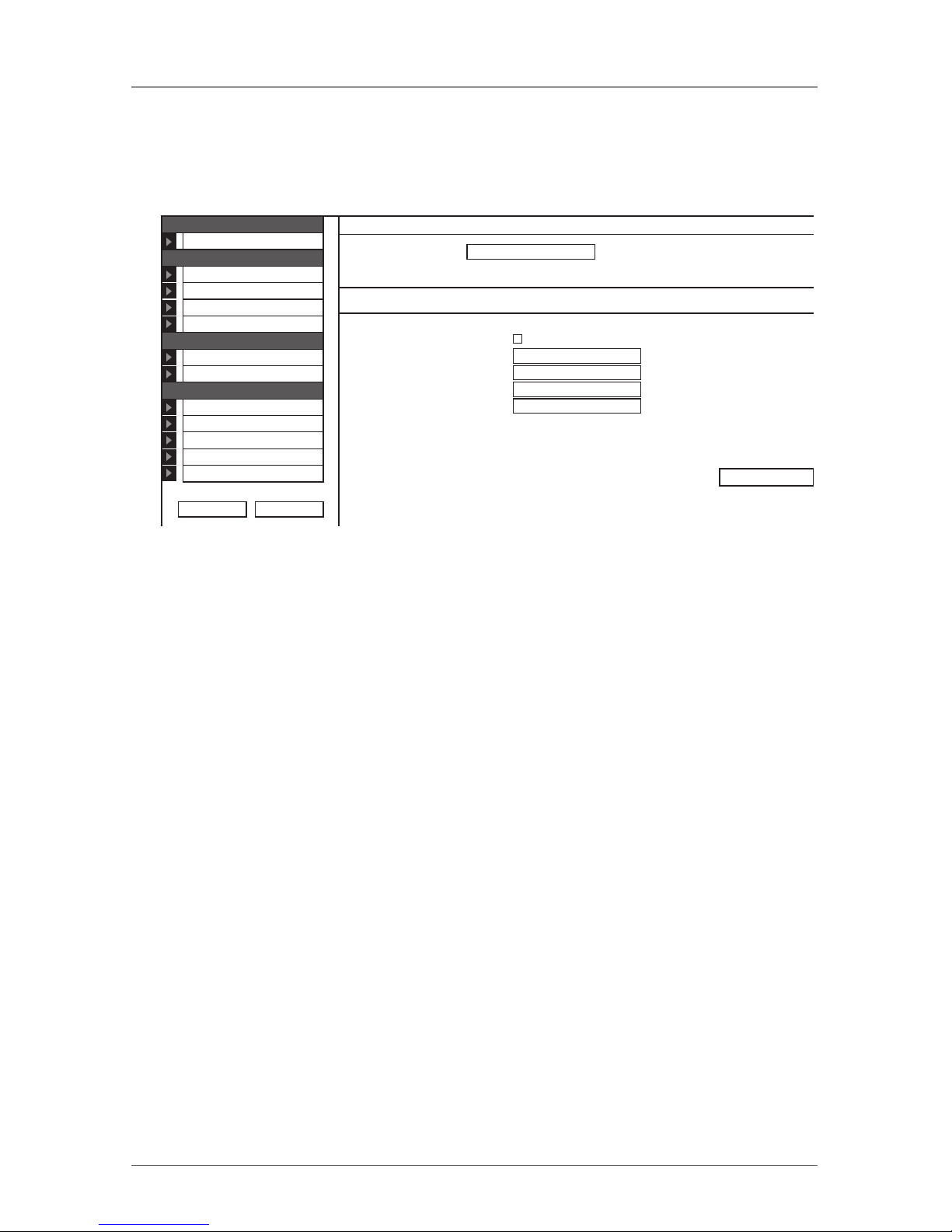
From the menu, click Configuration. The Network > Configuration page appears
(see Figure 7-1).
Device Name: ServSwitch Multiuser
Enable DHCP
MAC Address: 00:16:9D:02:DB:5B
IP A ddress: 192.168.2 .122
Subnet Mask: 255.255.255.0
Default Gateway: 192.168.2 .1
Save & Restart
Network > Configuration
LAN
Network
Configuration
Administration
User Settings
Switch Configuration
Power Management
User Ta rgets
Security
Settings
SSL Certificate
Maintenance
2x16 Switch Upgrade
SAMs Upgrade
Restore Factory Settings
Set Time & Date
Backup & Restore
Logout Restart
Figure 7-1. Network > Configuration page.
Consult your network administrator for the network settings.
Device name - Type a name for the ServSwitch Multiuser.
LAN
The LAN section contains the following (see Figure 7-1):
Enable DHCP — When a DHCP server is active on the same network to which
the ServSwitch is connected, DHCP provides automatic IP assignment.
When DHCP is disabled (Recommended) – You can assign a fixed IP address to
the ServSwitch.
Consult your Network Administrator about using the DHCP.
When DHCP is disabled, enter the IP Address, Subnet Mask, and Default
Gateway for LAN, as given to you by your Network Administrator.
These parameters can be configured locally from the OSD as explained in
Section 5.2.
Page 24
Page 22
724-746-5500 | blackbox.com
ServSwitch Multiuser
7.2 Administration > User Settings
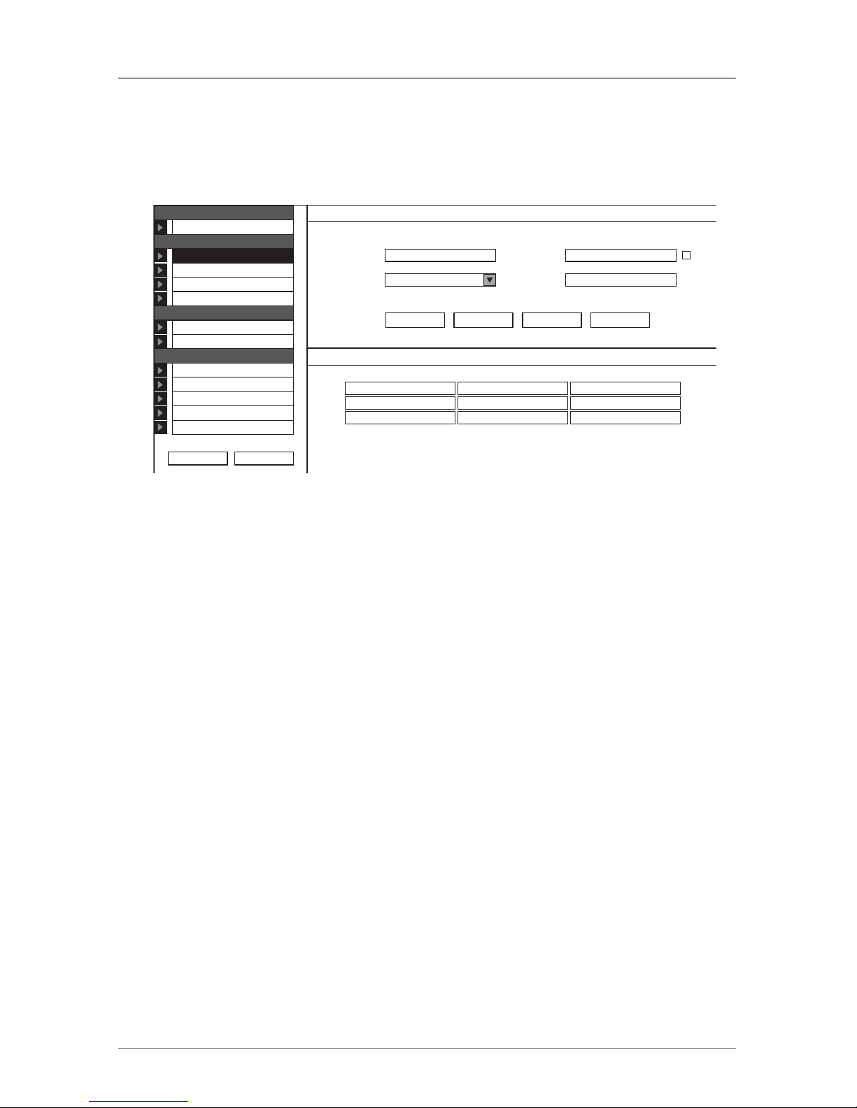
From the menu, click User Settings. The User settings screen appears as shown
in Figure 7-2.
User:
Permission:
1 Ephraim User not blocked
2 admin Administrator not blocked
3 Johnny User not blocked
Administrator
Password:
Block:
Confirm
Password:
New
Delete Apply Cancel
Administration > User SettingsNetwork
Configuration
Administration
User Settings
Switch Configuration
Power Management
User Ta rgets
Security
Settings
SSL Certificate
Maintenance
2x16 Switch Upgrade
SAMs Upgrade
Restore Factory Settings
Set Time & Date
Backup & Restore
Logout Restart
User Name Permission Status
Figure 7-2. User settings.
On this page an Administrator creates or deletes users.
There are 3 levels of user access:
• Administrator
• User
• View only
Administrator
An Administrator has unrestricted access to all windows and settings. An
Administrator can change the name and password and server access permissions
of all users.
User
A User can access/control permitted servers. A User has no access to the web
configuration interface.
View only
View only can view the screen of the currently accessed server without keyboard and mouse control.
Page 25

Page 23
724-746-5500 | blackbox.com
Chapter 7: Network Configuration
7.2.1 Adding a User
To add a user:
1. Click on the New button and type a name and a password. The password must
be at least 6 characters— letters or numbers—and must not include the user
name, even if other characters are added.
NOTE: The following “special” characters: &, <, >, ” cannot be used for either
the user name or password.
Depending on the security level chosen, the user name and password
parameters are different. See Chapter 9.
2. Select the permission type from the Permission box.
3. Click on the Apply button. The user appears in the list of users. The Permission
column shows the user level (Administrator, User, View Only). The Status
column shows whether the user is blocked or unblocked, explained in section
Section 7.2.3.
7.2.2 Deleting a User
To delete a user:
1. Select the user from the list.
2. Click on the Delete button.
3. Click on the Apply button, and the changes are saved.
7.2.3 Blocking a User
An alternative to deleting a user is blocking a user. This means that the user’s
name and password is stored, but the user can’t access the system. Check Block
to block a user. Uncheck Block to allow the user access.
Page 26
Page 24
724-746-5500 | blackbox.com
ServSwitch Multiuser
7.3 Administration > Switch Configuration
Assign unique names to the servers connected to the ServSwitch Multiuser, so
that users accessing the system can identify the servers easily.
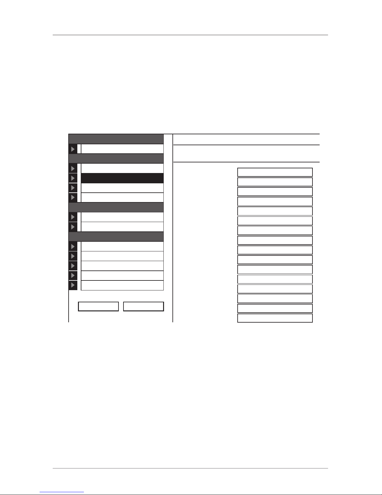
Follow the steps below:
1. From the menu, click Switch Configuration. The Switch Configuration window
appears, see Figure 7-3.
Server Name
1
2
3
4
5
6
7
8
9
10
11
12
13
14
15
16
Server 01
Server 02
Server 03
Server 04
Server 05
Server 06
Server 07
Server 08
Server 09
Server 10
Server 11
Server 12
Server 13
Server 14
Server 15
Server 16
Administration > Switch ConfigurationNetwork
Configuration
Administration
User Settings
Switch Configuration
Power Management
User Ta rgets
Security
Settings
SSL Certificate
Maintenance
2x16 Switch Upgrade
SAMs Upgrade
Restore Factory Settings
Set Time & Date
Backup & Restore
Logout Restart
Figure 7-3. Switch Configuration screen.
2. In the Server Name section, change the name of the connected servers by
selecting the server name and typing a new name. Click on the Apply button
to save changes.
Page 27
Page 25
724-746-5500 | blackbox.com
Chapter 7: Network Configuration
7.4 Administration > Power Management
Where you have a Serial Remote Power Switch (SRPS), connect it to the RPS
port of the ServSwitch Multiuser.
NOTE: The Serial Remote Power Switch (SRPS) port is not supported with the
currently released firmware at the time of this writing. This port is
reserved for future use.
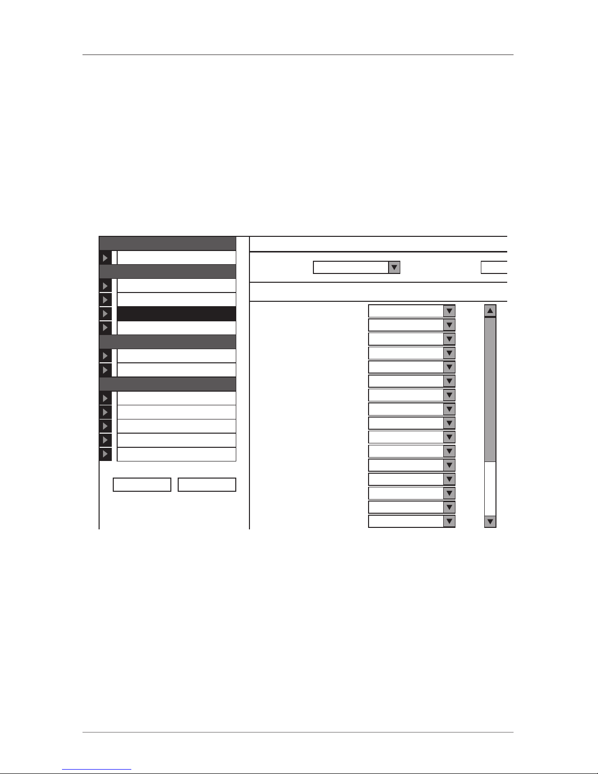
Configure the Power Management switch as follows:
1. From the menu, click Power Management. The Power Management window
appears, see Figure 7-4.
Server NameManaged by Sockets
1
2
3
4
5
6
7
8
9
10
11
12
13
14
15
16
None
None
None
None
None
None
None
None
None
None
None
None
None
None
None
None
Administration > Power ManagementNetwork
Configuration
Administration
User Settings
Switch Configuration
Power Management
User Ta rgets
Security
Settings
SSL Certificate
Maintenance
2x16 Switch Upgrade
SAMs Upgrade
Restore Factory Settings
Set Time & Date
Backup & Restore
Logout Restart
Number of
Sockets:
24
SeriaPDU Type:
Figure 7-4. Power Management screen.
2. Select the number of sockets on the power management switch in the Number
of Sockets drop-down menu (SRPS has 8).
3. Click on the Apply button. The appropriate number of Managed by Sockets and
Server Name drop-down menus appear.
4. Select the PDU type (default is SRPS).
5. Match the sockets to the servers. For each socket, select the server name
connected to it from the drop-down menu.
When there is a double or triple power supply, you need to assign multiple
sockets to the same KVM port.
Page 28
Page 26
724-746-5500 | blackbox.com
ServSwitch Multiuser
8. Administration > User Targets
Define the access rights of each user separately.
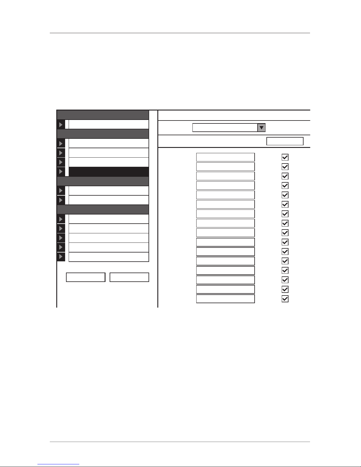
Follow these steps:
1. From the menu click User Targets. The User Targets Configuration window
appears (see Figure 8-1).
Server Name Control
1
2
3
4
5
6
7
8
9
10
11
12
13
14
15
16
File Server
KVManager
Windows 2003
ESX 3i 3.5
Windows XP
Server 06
Novell SuSE
Server 08
Server 09
Server 10
Server 11
Server 12
Server 13
Server 14
Server 15
Server 16
Administration > User Ta rgets ConfigurationNetwork
Configuration
Administration
User Settings
Switch Configuration
Power Management
User Ta rgets
Security
Settings
SSL Certificate
Maintenance
2x16 Switch Upgrade
SAMs Upgrade
Restore Factory Settings
Set Time & Date
Backup & Restore
Logout Restart
User: admin
Figure 8-1. User Targets Configuration.
2. Select a user from the User drop-down menu.
3. Check the servers the user can access (according to his access permissions). To
select all servers, press the Control button.
4. Click on the Apply button and the selection is saved.
5. Repeat the above steps for other users.
Page 29
Page 27
724-746-5500 | blackbox.com
Chapter 9: Security Settings
9. Security > Settings
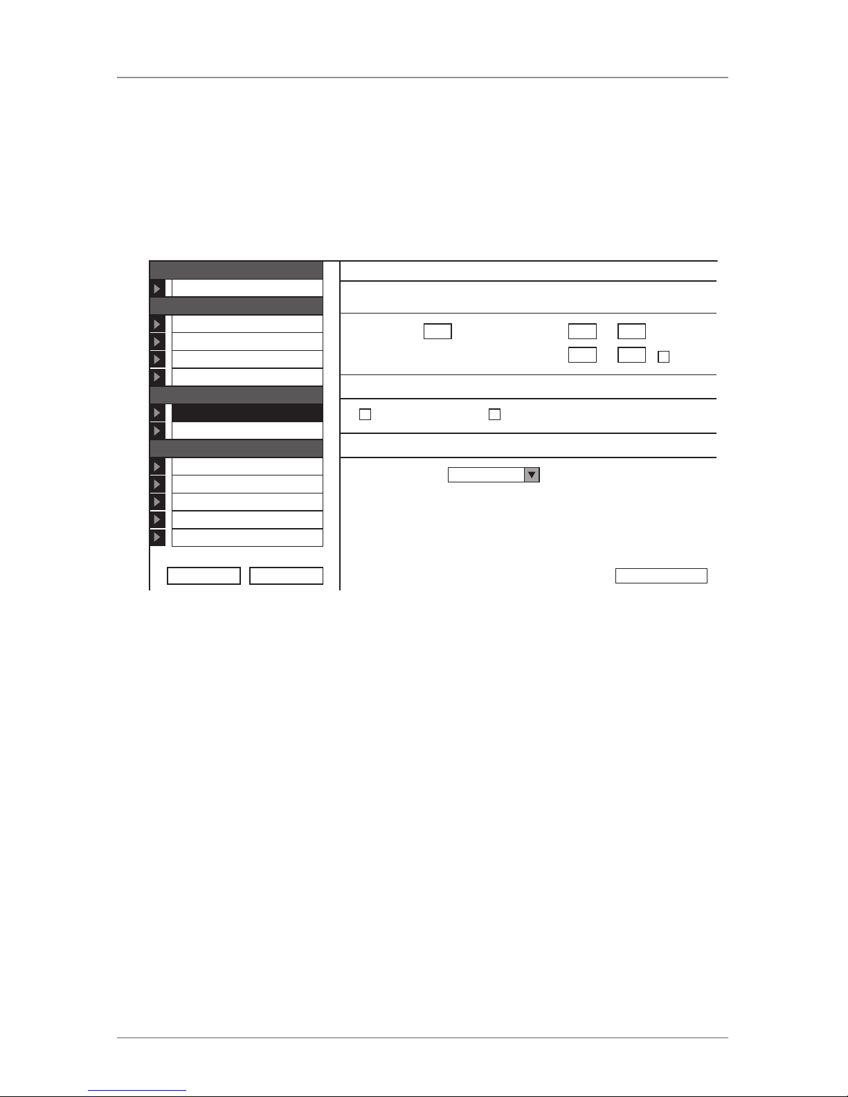
Configure the security features, such as Account Blocking, Password Policy, and
Idle Timeout, as explained below.
From the Security section, click on Settings. The Security Settings screen
appears (see Figure 9-1).
Security > Settings
Account Blocking
Network
Configuration
Administration
User Settings
Switch Configuration
Power Management
User Ta rgets
Security
Settings
SSL Certificate
Maintenance
2x16 Switch Upgrade
SAMs Upgrade
Restore Factory Settings
Set Time & Date
Backup & Restore
Password Policy
Idle Timeout
Logout Restart
5Block after
forever
10Disconnect aftermin. of inactivity
attempts within
High security policy OSD password enabled
Save & Restart
0H 3M
Block account for
0H 30M
Figure 9-1. Security Settings screen.
The Security Settings fields include the following:
Account Blocking—decide on the number of attempts to login with a wrong
username or password after which there is a time lock or a total block.
Password Policy—For OSD and Web configuration access you have the option
of a standard or high security password level. Table 9-1 shows the parameters for
the two options.
Page 30

Page 28
724-746-5500 | blackbox.com
ServSwitch Multiuser
Table 9-1. Standard vs. high security password level.
Standard security policy High security policy
6 characters or more 8 characters or more must include at
least 1 digit and 1 upper case letter
and 1 “special” character as follows
!@#$%^*()_-+=[]’:;?/{}
Must not include the user name Must not include the user name
Check the box to enable the high security password policy. Unchecked, the
standard security policy applies.
OSD password enabled—Access to the OSD can be password enabled or disabled (default), with the option of a standard or high security level of password as
explained above. Select the checkbox to enable password security. Note! All user
and server security settings depend on the OSD password being enabled.
Idle Timeout—Select the Timeout inactivity period after which the user is disconnected from the system. Choose No Timeout to disable Timeout.
Page 31
Page 29
724-746-5500 | blackbox.com
Chapter 10: Security SSL Settings
10. Security > SSL Certificate
You can install an SSL certificate.
To do so:
From the menu, select SSL Certificate. The install SSL Certificate page appears
(see Figure 10-1).
Certificate File:
Private Key File:
Key Password:
Install
Browse...
Browse...
Figure 10-1. Install SSL Certificate page.
Certificate File—Browse to locate the cer file (.ssl format).
Private Key File—Browse to locate the private key file (.pem format).
Key Password—Type the Key password.
Click on the Install button. The certificate installs. The device restarts automatically.
Page 32
Page 30
724-746-5500 | blackbox.com
ServSwitch Multiuser
11. Maintenance > Switch Upgrade
Upgrade the ServSwitch Multiuser firmware to take advantage of new features.
Download the firmware from the Support section of Black Box's Web site:
www.blackbox.com. Save the firmware file on the Client computer.
From the menu, select Switch Upgrade. The Upgrade window appears showing
the current firmware version (see Figure 11-1).
Switch Ver_1.0_B112_C1.0
Start
Browse...
Maintenance > Switch Upgrade
Figure 11-1. Firmware Upgrade.
1. Locate and upload the firmware file.
2. Click on the Start button. The upgrade starts. The unit reboots automatically.
After about 5 minutes the Login page appears.
Page 33
Page 31
724-746-5500 | blackbox.com
Chapter 12: Maintenance RICCs/SAMs Upgrade
12. Maintenance > SAMs Upgrade
Upgrade the SAM firmware to take advantage of new features. Download the
firmware from the Support section of Black Box's Web site—www.blackbox.com.
Save the firmware file on the Client computer.
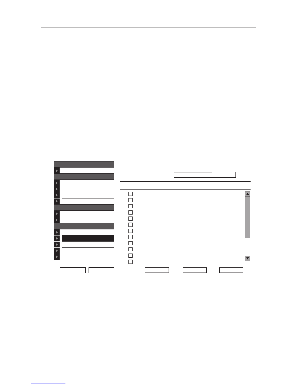
1. From the menu select SAMs Upgrade. The SAMs Upgrade window appears
showing the current firmware version see Figure 12-1.
2. Select the servers connected to the SAMs you wish to upgrade. Click on the All
button to select all.
3. Verify the current version of the firmware by pressing the Version button.
4. Locate and upload the firmware file.
5. Press the Start button and the firmware upgrades.
Device H/W Version F/W VersionSelect:
File Server
KVManager
Windows 2003
ESX 3i 3.5
Windows XP
Server 06
Novell SuSE
Server 08
Server 09
Server 10
Server 11
Server 12
Maintenance > SAMs UpgradeNetwork
Configuration
Administration
User Settings
Switch Configuration
Power Management
User Ta rgets
Security
Settings
SSL Certificate
Maintenance
2x16 Switch Upgrade
SAMs Upgrade
Restore Factory Settings
Set Time & Date
Backup & Restore
Logout Restart
All Version
Browse...
Start
Figure 12-1. SAMs Upgrade.
Page 34
Page 32
724-746-5500 | blackbox.com
ServSwitch Multiuser
13. Restore Factory Settings
You can restore the ServSwitch Multiuser unit to the factory settings. This
restores the original ServSwitch parameters, resetting all the information added by
the administrators, including network settings*, servers, users, and passwords.
* You have the option to preserve network settings—this is explained below.
WARNING: Once reset the data cannot be retrieved.
To restore factory settings:
1. From the menu select Restore Factory Settings. Restore Factory Settings appears.
See Figure 13-1.
Warning:
All device data will be lost!
Are you sure?
Restore
Preserve network settings
Figure 13-1. Restore factory settings.
2. Check the box if you want to preserve Network settings.
3. Click on the Restore button. The unit restarts.
Page 35
Page 33
724-746-5500 | blackbox.com
Chapter 14: Set Time and Date
14. Set Time & Date
The time and date set is used when recording log events (see Chapter 17).
To set the time and date:
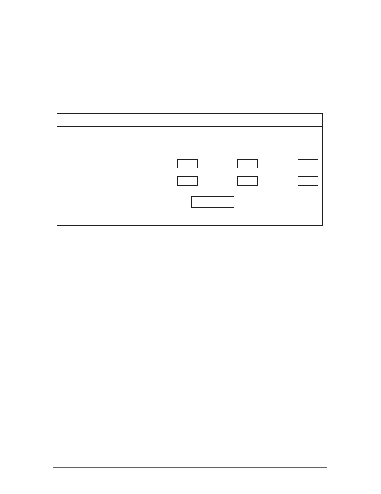
From the menu, select Time & Date. Figure 14-1 appears.
Maintenance > Set Time & Date
Apply
14Second:39Minute:16Hour:Time:
2009Year:5Month:26Day:Date:
Figure 14-1. Set Time & Date screen.
Type the appropriate parameters and double-click on the Apply button.
Page 36
Page 34
724-746-5500 | blackbox.com
ServSwitch Multiuser
15. Backup & Restore
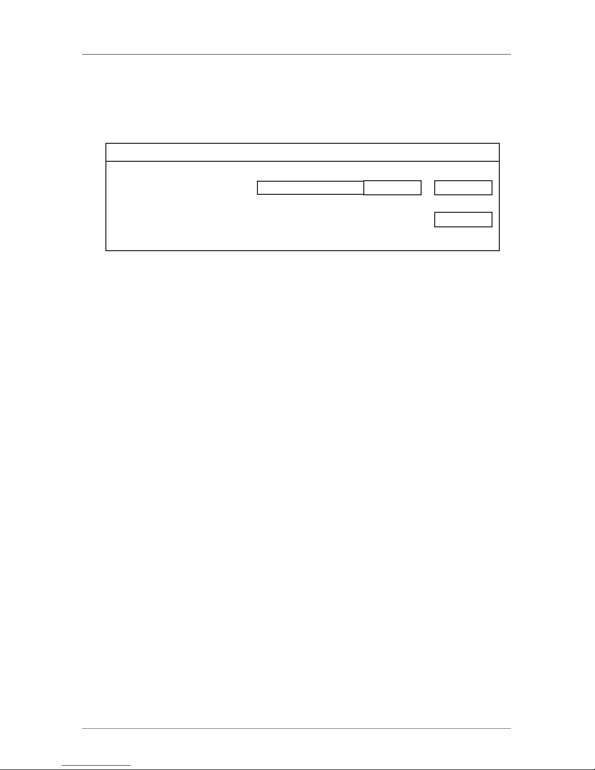
You can backup all configuration data and restore it at a later date. From the
menu select Backup & Restore. Figure 15-1 appears.
Restore Configuration data:
Backup Configuration data:
Save
Browse...
Apply
Maintenance > Backup
Figure 15-1. Backup & Restore.
To backup the configuration data, click on the Save button to save the file.
To restore the configuration data, browse to locate the file and click on the
Apply button. The device restarts.
Page 37

Page 35
724-746-5500 | blackbox.com
Chapter 16: Saving Changes and Logging Out
16. Saving Changes and Logging Out
To save any configuration changes, click on the relevant button on the current
page. This could be the Save & Restore button or just the Apply button.
To restart the ServSwitch press the Restart button.
To exit the Configuration menu and close the session, click on the Logout but-
ton.
Only one Administrator can log into the Configuration area at a time. After the
idle Timeout—see Chapter 9—the session terminates.
Page 38
Page 36
724-746-5500 | blackbox.com
ServSwitch Multiuser
17. Event Log
To see a log of all system events:
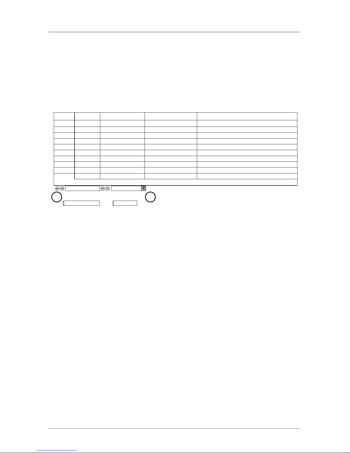
From the Targets page menu (see Figure 6-1), select Event Log. The following
screen appears.
User Severity EventTime Details
admin Info User login succeeded Wed 28 Jan 2004 16:31:52 Host:192.168.200.97,Peer:192.168.200.23,Level:Admin
admin Info Config logout Wed 28 Jan 2004 16:06:39 Peer:192.168.200.23
admin Info Logout Wed 28 Jan 2004 14:50:49 Host:192.168.200.97,Peer:192.168.200.23,Level:Admin
admin Info Config login succeeded Wed 28 Jan 2004 14:50:49 192.168.200.23
admin Info User login succeeded Wed 28 Jan 2004 14:50:34 Host:192.168.200.97,Peer:192.168.200.23,Level:Admin
admin Info Config logout Tue 27 Jan 2004 21:11 :51 Peer:192.168.200.79
admin Info Config login succeeded Tue 27 Jan 2004 21:09:51 192.168.200.79
admin Info Logout Tue 27 Jan 2004 21:09:51 Host:192.168.200.97,Peer:192.168.200.79,Level:Admin
admin Info User login succeeded Tue 27 Jan 2004 21:09:49 Host:192.168.200.97,Peer:192.168.200.79,Level:Admin
Info System boot Tue 27 Jan 2004 20:19:21 Ve rsion 1.0
Event Log
To tal Events: 10
Download as File Clear Log
201/1
A B
Figure 17-1. Events log screen.
Navigate through the events pages using the forward or backward arrows,
marked as (A) in Figure 17-1.
From the drop down menu, marked as (B) in Figure 17-1, choose the number of
events that will appear on each page—between 10 and 40.
17.1 Downloading the log
You can download and save the log.
To do so, click on the Download as File button and save as a .csv file. The file
can be viewed using Microsoft Excel or compatible software.
17.2 Clearing the Log
To clear the log, click on the Clear Log button. A prompt appears asking if you
first want to save the log.
Page 39
Page 37
724-746-5500 | blackbox.com
Chapter 18: Operating the System via the OSD
18. Operating the System via the OSD
To display the OSD:
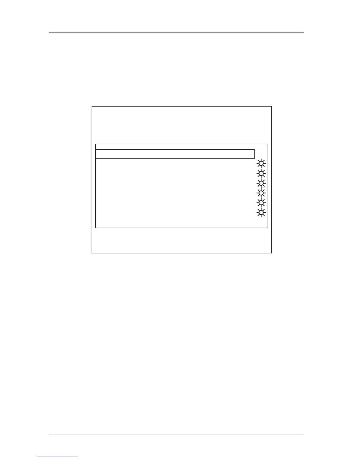
1. From the local keyboard, press the left Shift key twice. The OSD Main window
appears. See Figure 18-1.
Black Box ServSwitch Multiuser
MAIN
01 File Server
02 Mail Server
03 AD DC
04 ESX 3i 3.5
05 Windows 2008
06 Firewall
07 Novell SuSE
08 RedHat Ent
-- NAME USER PM
MOVE LABEL F1 ESC-LOGOUT
TUNING F5 F2-SETTING
Figure 18-1. OSD Main window.
18.1 Navigating the OSD Main Window
To navigate up and down use the Up and Down arrow keys.
To exit the OSD press Esc.
18.2 Selecting a Computer
To select a computer:
1. Navigate to the desired computer line.
Or, type the two-digit port number of the desired computer.
2. Press Enter. The selected computer is accessed. A confirmation label appears
showing which computer is accessed.
18.3 Power Management Hotkey – Left Shift, F12
To power manage a server connected to a power management switch:
1. Navigate to the computer line you desire to power manage.
Page 40
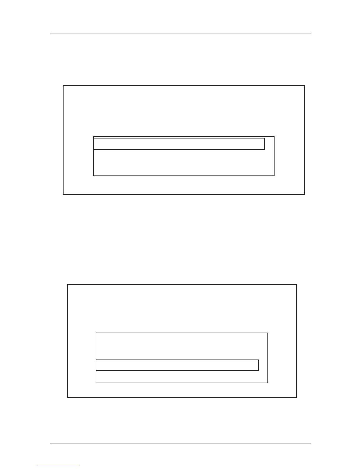
Page 38
724-746-5500 | blackbox.com
ServSwitch Multiuser
2. Press left Shift, F12. The Power Control dialog box appears, see Figure 18-2.
NOTE: If you change the OSD hotkey from Shift, Shift to Ctrl, Ctrl, then the power
management hotkey becomes left Ctrl, F12.
Black Box ServSwitch Multiuser
POWER CONTROL
POWER ON
POWER OFF
POWER CYCLE
Novell SuSE
ESC BACK ENTER SELECT
Figure 18-2. Power Control dialog box.
3. Use the arrow keys to navigate up and down and press Enter to select the
power option.
4. A prompt appears; see Figure 18-3. Select the desired option and press Enter.
The power command is sent.
Black Box ServSwitch Multiuser
POWER CONTROL
POWER ON Johnny
NO
YES
Johnny
ESC BACK
Figure 18-3. Power prompt.
Page 41
Page 39
724-746-5500 | blackbox.com
Chapter 18: Operating the System via the OSD
18.4 Moving the Confirmation Label – F1
The confirmation label appears for 30 seconds. It shows which computer is cur-
rently accessed and can be positioned anywhere on the screen.
To position the label from the Main window:
1. Navigate to a computer line using the Up and Down arrow keys.
2. Press F1. The selected screen image and Confirmation label appear.
3. Use the arrow keys to move the label to the desired position.
4. Press Esc to save and exit.
18.5 Tuning – F5
You can tune the image of any computer screen from the Main window.
To adjust the screen image:
1. Navigate to the computer line you wish to adjust.
2. Press F5. The screen image of the selected computer appears, together with
the Image Tuning label, see Figure 18-4.
Black Box ServSwitch Multiuser
TUNING
Equalize: 050
Figure 18-4. Image Tuning label.
3. Adjust the image by using the Right and Left Arrow keys.
4. When the image is satisfactory, press Esc.
NOTE: Picture quality is relative to distance. The further away a computer is
from the Multiuser, the lower the image quality, and the more tuning is
needed. So place the higher resolution computers closer to the Switch.
Page 42
Page 40
724-746-5500 | blackbox.com
ServSwitch Multiuser
18.6 The Settings Window - F2
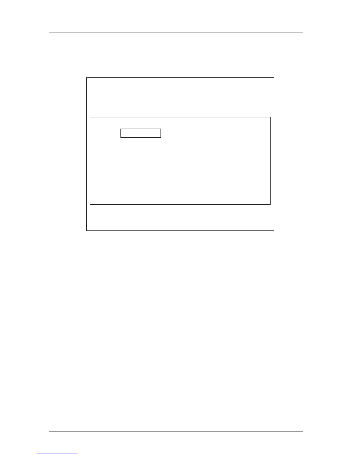
Press F2. The Settings window appears (see Figure 18-5).
Black Box ServSwitch Multiuser
SETTINGS
MAC ADD 00:50:C2:36:E4:07
DHCP ENABLED
IP ADDRESS 192.168.0 .254
SUBNET MASK 255.255.255.0
GATEWAY 192.168.0 .1
HOTKEY: Shift-Shift
KEYBOARD LANGUAGE: English
Save Parm-ESC DDC-F10
Figure 18-5. Settings window.
In the Settings window navigate downwards using the Tab key. At the bottom
of the window, press Tab to go to the top of the window. Change settings by
typing in the selected area or by pressing the spacebar—whichever is relevant.
Changing the network parameters from the OSD is explained with the initial
configuration in Section 5.2.
From the Settings window you can do the following:
HOTKEY – By pressing Shift, Shift the OSD appears. You can replace Shift, Shift
with any of the following:
• Ctrl, Ctrl
• Ctrl, F11
• Print Screen
Press the Spacebar to toggle between options.
To display the OSD press the new hotkey.
KEYBOARD LANGUAGE—Press the Spacebar to toggle between the language
options. It can be changed to French or German.
Page 43

Page 41
724-746-5500 | blackbox.com
Chapter 18: Operating the System via the OSD
18.7 DDC
Display Data Channel (DDC) is a VESA standard for communication between a
monitor and a video adapter.
From the Settings window, input the DDC information of the monitor connected to the switch into the memories of all connected SAMs when first installing the
system.
To input the DDC information:
Press F10. “Please wait” flashes a few times and disappears. The monitor’s DDC
information is sent to all SAMs and stored in their memory.
Updating the DDC information
Update the DDC information in any of the following circumstances:
• When replacing the monitor connected to the Multiuser
• When adding a new SAM to the system
• When reconnecting an existing SAM that was temporarily used in a different system
To update the DDC information, repeat the steps as described above.
18.8 Saving Changes to the Settings
To save changes to the settings and return to the Main window, press Esc.
Page 44

Page 42
724-746-5500 | blackbox.com
ServSwitch Multiuser
19. Troubleshooting
19.1 Calling Black Box
If you determine that your ServSwitch Multiuser is malfunctioning, do not
attempt to alter or repair the unit. It contains no user-serviceable parts. Contact
Black Box Technical Support at 724-746-5500.
Before you do, make a record of the history of the problem. We will be able to
provide more efficient and accurate assistance if you have a complete description,
including:
• the nature and duration of the problem.
• when the problem occurs.
• the components involved in the problem.
• any particular application that, when used, appears to create the problem or
make it worse.
19.2 Shipping and Packaging
If you need to transport or ship your ServSwitch Multiuser:
• Package it carefully. We recommend that you use the original container.
• If you are returning the unit, make sure you include everything you received
with it. Before you ship for return or repair, contact Black Box to get a Return
Authorization (RA) number.
Page 45

Page 43
724-746-5500 | blackbox.com
Appendix: RPS (Remote Power Switching)
Appendix. RPS (Remote Power Switching)
The remote power switch port pinning is shown in Table A-1. A RJ-12 to DB9
cable pinning is shown in Table A-2.
Table A-1. Remote power switch port pinning, RJ-45 connector.
3 (TX)
4 (RX)
6 (GND)
To interface the RPS port with a computer’s DB9 male serial port, you can use
the following pinning for an RJ-12 to DB9 cable.
Table A-2. RJ-12 to DB9 cable pinning.
RJ-11 male DB9 female
2 (TX) 2 (RX)
3 (RX) 3 (TX)
5 (GND) 5 (GND)
Page 46

Black Box Tech Support: FREE! Live. 24/7.
Tech support the
way it should be.
Great tech support is just 20 seconds away at
724-746-5500 or blackbox.com.
724-746-5500 | blackbox.com
About Black Box
Black Box Network Services is your source for more than 118,000 networking
and infrastructure products. You’ll find everything from cabinets and racks and
power and surge protection products to media converters and Ethernet switches
all supported by free, live 24/7 Tech support available in 20 seconds or less.
©
Copyright 2010. All rights reserved.
 Loading...