

Page 1

FEBRUARY 2001
KV780A
KV780AE
POWER
STATUS SEND
KEYBOARD / MONITOR / MOUSE COMPUTER
PROFESSOR
STUDENT MODULE
POWERSTATUS SEND
KEYBOARD / MONITOR / MOUSE COMPUTER
PROFESSOR
EDUCATIONAL/TRAINING SYSTEM
SYSTEM CONTROL
MODULE
PROFESSOR
FREE tech support 24 hours a day, 7 days a week: Call 724-746-5500 or fax 724-746-0746.
Mailing address: Black Box Corporation, 1000 Park Dr., Lawrence, PA 15055-1018
World-Wide Web: www.blackbox.com • E-mail: info@blackbox.com
© Copyright 2001. Black Box Corporation. All rights reserved.
Customer Support Information:
Page 2

1
THE SERVSWITCH™ FAMILY
Welcome to the ServSwitch
TM
Family!
Thank you for purchasing a BLACK BOX®ServSwitch™Brand KVM switch! We
appreciate your business, and we think you’ll appreciate the many ways that your
new ServSwitch keyboard/video/mouse switch will save you money, time, and
effort.
That’s because our ServSwitch family is all about breaking away from the
traditional, expensive model of computer management. You know, the one-sizefits-all-even-if-it-doesn’t model that says, “One computer gets one user station, no
more, no less.” Why not a single user station (monitor, keyboard, and mouse) for
multiple computers—even computers of different platforms? Why not a pair of
user stations, each of which can control multiple computers? Why not multiple
user stations for the same computer?
With our ServSwitch products, there’s no reason why not. We carry a broad line
of robust solutions for all these applications. Do you have just two PCs, and need
an economical alternative to keeping two monitors, keyboards, and mice on your
desk? Or do you need to share dozens of computers, including a mix of IBM
®
PC,
RS/6000
®
, Apple®Macintosh®, Sun Microsystems®, and SGI®compatibles among
multiple users with different access levels? Does your switch have to sit solidly on a
worktable and use regular everyday cables? Or does it have to be mounted in an
equipment rack and use convenient many-to-one cables? No matter how large or
small your setup is, no matter how simple or how complex, we’re confident we
have a ServSwitch system that’s just right for you.
The ServSwitch
™
family from Black Box—the one-stop answer for all your KVM-
switching needs!
*
This manual will tell you all about your new ServSwitch™ Professor, including
how to install, operate, and troubleshoot it. For an introduction to the ServSwitch
Professor, see Chapter 2. This manual is shipped with the ServSwitch Professor
Instructor Kit, whose product codes are:
KV780A
KV780AE
This manual also covers the ServSwitch Professor Student Kits, whose product
codes are:
KV781A
KV781AE
KV782A
KV782AE
Page 3

2
SERVSWITCH™ PROFESSOR
TRADEMARKS USED IN THIS MANUAL
BLACK BOX and the logo are registered trademarks, and ServSwitch and
ServSwitch Professor are trademarks, of Black Box Corporation.
Apple and Macintosh are registered trademarks of Apple Computer, Inc.
IBM, PC/AT, PS/2, and RS/6000 are registered trademarks, and PC/XT is a
trademark, of International Business Machines Corporation.
Microsoft, Windows, and IntelliMouse are registered trademarks or trademarks of
Microsoft Corporation in the United States and/or other countries.
Sun Microsystems is a registered trademark of Sun Microsystems, Inc. in the
United States and other countries.
Any other trademarks mentioned in this manual are acknowledged to be the property of the
trademark owners.
Page 4

3
FCC/IC STATEMENTS
FEDERAL COMMUNICATIONS COMMISSION AND INDUSTRY CANADA
RADIO-FREQUENCY INTERFERENCE STATEMENTS
This equipment generates, uses, and can radiate radio-frequency energy, and if not
installed and used properly, that is, in strict accordance with the manufacturer’s
instructions, may cause interference to radio communication. It has been tested
and found to comply with the limits for a Class A computing device in accordance
with the specifications in Subpart J of Part 15 of FCC rules, which are designed to
provide reasonable protection against such interference when the equipment is
operated in a commercial environment. Operation of this equipment in a
residential area is likely to cause interference, in which case the user at his own
expense will be required to take whatever measures may be necessary to correct the
interference.
Changes or modifications not expressly approved by the party responsible for
compliance could void the user’s authority to operate the equipment.
This digital apparatus does not exceed the Class A limits for radio noise emission from digital
apparatus set out in the Radio Interference Regulation of the Canadian Department of
Communications.
Le présent appareil numérique n’émet pas de bruits radioélectriques dépassant les limites
applicables aux appareils numériques de la classe A prescrites dans le Règlement sur le
brouillage radioélectrique publié par le ministère des Communications du Canada.
Page 5

4
SERVSWITCH™ PROFESSOR
EUROPEAN UNION DECLARATION OF CONFORMITY
This equipment complies with the requirements of the European EMC Directive
89/336/EEC.
Page 6

5
NOM STATEMENT
NORMAS OFICIALES MEXICANAS (NOM)
ELECTRICAL SAFETY STATEMENT
INSTRUCCIONES DE SEGURIDAD
1. Todas las instrucciones de seguridad y operación deberán ser leídas antes de
que el aparato eléctrico sea operado.
2. Las instrucciones de seguridad y operación deberán ser guardadas para
referencia futura.
3. Todas las advertencias en el aparato eléctrico y en sus instrucciones de
operación deben ser respetadas.
4. Todas las instrucciones de operación y uso deben ser seguidas.
5. El aparato eléctrico no deberá ser usado cerca del agua—por ejemplo, cerca
de la tina de baño, lavabo, sótano mojado o cerca de una alberca, etc..
6. El aparato eléctrico debe ser usado únicamente con carritos o pedestales que
sean recomendados por el fabricante.
7. El aparato eléctrico debe ser montado a la pared o al techo sólo como sea
recomendado por el fabricante.
8. Servicio—El usuario no debe intentar dar servicio al equipo eléctrico más allá
a lo descrito en las instrucciones de operación. Todo otro servicio deberá ser
referido a personal de servicio calificado.
9. El aparato eléctrico debe ser situado de tal manera que su posición no
interfiera su uso. La colocación del aparato eléctrico sobre una cama, sofá,
alfombra o superficie similar puede bloquea la ventilación, no se debe colocar
en libreros o gabinetes que impidan el flujo de aire por los orificios de
ventilación.
10. El equipo eléctrico deber ser situado fuera del alcance de fuentes de calor
como radiadores, registros de calor, estufas u otros aparatos (incluyendo
amplificadores) que producen calor.
11. El aparato eléctrico deberá ser connectado a una fuente de poder sólo del
tipo descrito en el instructivo de operación, o como se indique en el aparato.
Page 7

6
SERVSWITCH™ PROFESSOR
12. Precaución debe ser tomada de tal manera que la tierra fisica y la polarización
del equipo no sea eliminada.
13. Los cables de la fuente de poder deben ser guiados de tal manera que no
sean pisados ni pellizcados por objetos colocados sobre o contra ellos,
poniendo particular atención a los contactos y receptáculos donde salen del
aparato.
14. El equipo eléctrico debe ser limpiado únicamente de acuerdo a las
recomendaciones del fabricante.
15. En caso de existir, una antena externa deberá ser localizada lejos de las lineas
de energia.
16. El cable de corriente deberá ser desconectado del cuando el equipo no sea
usado por un largo periodo de tiempo.
17. Cuidado debe ser tomado de tal manera que objectos liquidos no sean
derramados sobre la cubierta u orificios de ventilación.
18. Servicio por personal calificado deberá ser provisto cuando:
A: El cable de poder o el contacto ha sido dañado; u
B: Objectos han caído o líquido ha sido derramado dentro del aparato; o
C: El aparato ha sido expuesto a la lluvia; o
D: El aparato parece no operar normalmente o muestra un cambio en su
desempeño; o
E: El aparato ha sido tirado o su cubierta ha sido dañada.
Page 8

7
TABLE OF CONTENTS
Contents
Chapter Page
1. Specifications ............................................................................................. 7
2. Introduction ............................................................................................... 9
2.1 The Complete Package ....................................................................... 9
2.2 Features ............................................................................................. 10
2.3 The ServSwitch Professor Illustrated ............................................... 12
2.3.1 The Front Panel .................................................................... 12
2.3.2 The Rear Panel ...................................................................... 13
2.3.3 The Bottom Panel ................................................................. 14
2.4 Cable Requirements ......................................................................... 15
3. Installation ................................................................................................ 16
3.1 Quick Setup Guide ........................................................................... 16
3.2 Placement .......................................................................................... 17
3.3 The Installation Procedure .............................................................. 17
3.3.1 Setting the Unit’s Bus Address ............................................. 17
3.3.2 Rackmounting (Optional) .................................................... 18
3.3.3 Connecting the Keyboard, Monitor, and Mouse ................ 19
3.3.4 Connecting the CPU ............................................................. 19
3.3.5 Connecting the Bus ............................................................... 20
3.3.6 Powering the Professor ......................................................... 21
3.3.7 Testing the Professor ............................................................ 22
4. Operation ............................................................................................... 23
4.1 Guidelines for Using the ServSwitch Professor with
Your Equipment .......................................................................... 23
4.1.1 CPUs ....................................................................................... 23
4.1.2 Mouse and Keyboard ............................................................ 23
4.1.3 Monitor .................................................................................. 25
4.2 Keyboard-Command Summary ........................................................ 27
4.3 The Commands in Detail ................................................................. 30
4.3.1 View Station ........................................................................... 30
4.3.2 Share Station ......................................................................... 31
4.3.3 Control Station ...................................................................... 31
4.3.4 Show to Station ...................................................................... 31
4.3.5 Enable Station ....................................................................... 32
4.3.6 Disable Station ....................................................................... 32
4.3.7 Freeze Station ........................................................................ 32
Page 9

8
SERVSWITCH™ PROFESSOR
Chapter Page
4. Operation: Hardware and Commands (continued)
4.3 The Commands in Detail (continued)
4.3.8 XView Station at Another Station ........................................ 33
4.3.9 XShare Station with Another Station .................................. 34
4.3.10 Select Station ......................................................................... 36
4.3.11 Switch to the Next or Previous Station in Numeric Order .. 36
4.3.12 Switch to the Previously Selected Station ............................ 37
4.3.13 Turn Scan Mode ON or OFF ............................................... 37
4.3.14 Keep Settings ......................................................................... 38
4.3.15 Set Scan-Delay Time .............................................................. 38
4.3.16 Set Minimum and Maximum Scan Stations ........................ 38
4.3.17 Set Screen-Saver Interval ...................................................... 39
4.3.18 Set Keyboard Timeout .......................................................... 39
4.3.19 Set Keyboard Mode .............................................................. 41
4.3.20 Set Keyboard Typematic ....................................................... 42
4.3.21 Set Mouse Translation .......................................................... 44
4.3.22 Set Power-On Station ............................................................ 44
4.3.23 Set Access Level ..................................................................... 45
4.3.24 Reset ....................................................................................... 46
4.3.25 Send Null Byte (PS/2 Type Mice Only) .............................. 47
4.3.26 Identify ROM ......................................................................... 47
5. Troubleshooting ...................................................................................... 48
5.1 Restoring Factory-Default Settings ................................................... 48
5.2 Common Problems ........................................................................... 49
5.3 Calling Black Box .............................................................................. 54
5.4 Shipping and Packaging .................................................................. 54
Appendix A: NVRAM Factory Defaults ......................................................... 55
Appendix B: Cable Product Codes ................................................................ 57
Appendix C: Rackmounting the ServSwitch Professor ................................. 59
Page 10

9
CHAPTER 1: Specifications
1. Specifications
Compliance — FCC Part 15 Subpart J Class A, IC Class/classe A;
230-VAC (“-AE” suffix) models: CE
Standards — With original Serv cabling: VGA (color or monochrome/
page white) video;
With original Serv cabling (minimal) or coaxial cabling
(recommended): SVGA video;
With coaxial cabling: XGA (color or monochrome) video
Interfaces — All COMPUTER, KEYBOARD/MONITOR/MOUSE, and
BUS ports:
Proprietary composite of IBM PS/2 or PC/AT
keyboard, PS/2 or RS-232 mouse, and VGA/SVGA/
XGA video;
RS-232 port: Proprietary variant of EIA/TIA RS-232 using
RJ-12 (“6-wire RJ-11”) connectors, DTE;
Resolution — With original Serv cabling: Up to 1024 x 768
noninterlaced;
With coaxial cabling: Up to 1280 x 1024 noninterlaced
Maximum
Distance — To local equipment (depends on the CPUs, monitors,
video resolutions, and the length of bus cable between
CPUs and user equipment—see Section 4.1.3):
5 ft. (1.5 m) of total original Serv cable or at least 20 ft.
(6.1 m) of coaxial cable—possibly as much as 100 ft.
(30.5 m), depending on the devices—from any
ServSwitch Professor to any device attached to it;
Between Professor units (depends on the video
resolution):
250 ft. (76.2 m) of total bus cable, end to end
User Controls — Keyboard commands;
Bottom-mounted 8-position unit-address DIP switch;
Rear-mounted power (ON/OFF) pushbutton
Indicators — All front-mounted LEDs:
(1) Power;
(1) Status;
(1) Send
Page 11

10
SERVSWITCH™ PROFESSOR
Connectors — Front-mounted:
(1) DB25 female for CPU;
(1) DB25 female for keyboard, monitor, and mouse;
Rear-mounted:
(2) 13W3 female: (1) bus in, (1) bus out;
(1) RJ-12 (“6-wire RJ-11”) female for RS-232;
(1) 5-pin DIN female for power
Maximum
Altitude — 10,000 ft. (3048 m)
Temperature
Tolerance — 32 to 131˚F (0 to 55˚C)
Humidity
Tolerance — 5 to 80% noncondensing
Enclosure — Fully shielded steel
Power — KV780A, KV781A, KV782A:
From wallmount power supply PS023:
Optimal input: 120 VAC, 60 Hz, 100 mA;
Output: 17 VAC CT, 700 mA;
Consumption: Up to 11.9 VA (11.9 watts);
KV780AE, KV781AE, KV782AE:
From desktop power supply PS023E:
Optimal input: 230 VAC, 50 Hz, 60 mA;
Output: 17 VAC CT, 700 mA;
Consumption: Up to 11.9 VA (11.9 watts)
Size — 2.3"H x 8.8"W x 4.9"D (5.8 x 22.4 x 12.5 cm)
Weight — 3 lb. (1.4 kg)
Page 12

11
CHAPTER 2: Introduction
2. Introduction
Thank you for choosing a ServSwitch™ Professor. Designed for plug-and-play
operation, your new Professor will simplify your job by helping you organize your
applications involving multiple IBM
®
PC compatible computers. In particular, the
ServSwitch Professor is especially designed for classroom applications so the
instructor can access students’ stations.
This chapter describes everything that comes with the ServSwitch Professor Kit,
the external and operating features of the Professor, and the cabling you’ll need
for the Professor.
2.1 The Complete Package
What you get in your ServSwitch Professor Kit depends on which type of Kit you
ordered. The Instructor Kit (product code KV780A or KV780AE) comes with:
• A ServSwitch Professor System Control Module (SCM).
• (1) 1-ft. (0.3-m) standard PS/2 type User Cable.
• (1) 1-ft. (0.3-m) standard PC/AT type User Cable.
• (1) 5-ft. (1.5-m) coaxial PS/2 type CPU Cable with PC/AT adapters.
• (2) Bus terminators.
• (1) Power supply.
• (1) Copy of this manual.
• (1) Keyboard template.
The Student Kit for PS/2 (product code KV781A or KV781AE) comes with:
• A ServSwitch Professor Student Module (STM).
• (1) 1-ft. (0.3-m) standard PS/2 type User Cable.
• (1) 5-ft. (1.5-m) coaxial PS/2 type CPU Cable.
• (1) 10-ft. (3-m) coaxial bus cable.
• (1) Power supply.
The Student Kit for PC/AT (product code KV782A or KV782AE) comes with:
• A ServSwitch Professor Student Module (STM).
• (1) 1-ft. (0.3-m) standard PC/AT type User Cable.
• (1) 5-ft. (1.5-m) coaxial PC/AT type CPU Cable.
• (1) 10-ft. (3-m) coaxial bus cable.
• (1) Power supply.
Page 13

12
SERVSWITCH™ PROFESSOR
2.2 Features
Some of the useful features of the ServSwitch Professor:
• The instructor can access any student’s computer in three modes:
View mode—see student’s station without disturbing student’s keyboard or
mouse;
Share mode—see student’s station with interactive keyboard and mouse
sharing;
Control mode—see student’s station with complete control over their keyboard
and mouse.
• The instructor can disable any student’s station in two modes:
Disable—Student’s screen is blanked and keyboard and mouse are locked
out;
Freeze—Student’s screen remains on, but all keyboard and mouse activity is
locked out.
• The instructor can let students interact with each other in two modes:
XView mode—students see another student’s station without disturbing their
keyboard or mouse;
XShare mode—students see another student’s station with interactive
keyboard and mouse sharing.
• “Show mode” allows instructors to send their screen to any or all students.
• “Scan mode” allows instructor to sequentially view each student’s computer.
• The instructor can even allow students to view or share control of each other’s
CPUs, or allow students to share control of the instructor’s own CPU.
• You can connect one instructor station and up to 254 student stations.
• Single cable connection between units simplifies installation.
• The bus cabling between units uses high-quality 13W3 video connectors for
crystal-clear video even at long distances.
• Data on the bus is packetized, as if it were network data, for fast and highly
reliable delivery of keyboard, mouse, and control information.
• Easily set each unit’s network address with the bottom-panel DIP switch.
• Keyboard-timeout feature allows sharing of CPUs.
Page 14

13
CHAPTER 2: Introduction
• Drives video, keyboard, and mouse up to 100 ft. (30.5 m) away.
• Supports up to 1280 x 1024 noninterlaced video resolution.
• LEDs show bus status and video-sending state.
• Screen-blanking function turns off video after 1 to 999 seconds of inactivity.
• Use the previous-channel command for easy back-and-forth access to two
CPUs.
• All settings can be saved in nonvolatile memory.
• Available in 117-VAC or 230-VAC models.
• 19," 23," and 24" rackmount kits are also available.
Page 15
14
SERVSWITCH™ PROFESSOR
2.3 The ServSwitch Professor Illustrated
2.3.1 THEF
RONTPANEL
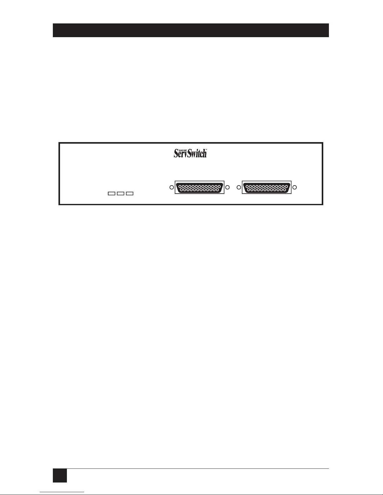
The ServSwitch Professor’s front panel features two local-equipment connectors
and three LED indicators. To familiarize yourself with these controls and
indicators, refer to Figure 2-1 and the descriptions that follow. (The figure shows a
System Control Module, but Student Modules will have the same components in
the same places.)
Figure 2-1. The front panel of a ServSwitch Professor.
Panel Label Description
POWER This LED lights to indicate that unit is powered ON.
STATUS This LED flashes once a second to show bus connection. Also
flashes in response to keyboard or mouse activity.
SEND This LED lights to show that the unit is sending video over the
coax bus (one or more monitors might be receiving the video).
KEYBOARD/ Attach the keyboard, mouse, and monitor of a user station to
MONITOR/ this DB25 female connector using a User Cable (“MKM Adapter
MOUSE Cable”). At the ServSwitch end, this cable has a DB25 male
connector; at the other ends, it has appropriate connectors to
plug into your monitor, keyboard, and mouse cables. Only one
User Cable is needed. See Section 2.4.
COMPUTER Attach the local CPU to this port with a “CPU Cable” (“CPU
Adapter Cable”). At the Professor end this cable has a DB25
male connector; at the other ends, it has appropriate connectors
to plug into your CPU’s video, keyboard, and mouse ports. This
cable takes the signals that would normally pass between the
CPU’s ports and the monitor, keyboard, and mouse, and carries
them between the CPU’s ports and the Professor station instead.
POWER STATUS SEND
KEYBOARD / MONITOR / MOUSE COMPUTER
PROFESSOR
EDUCATIONAL/TRAINING SYSTEM
SYSTEM CONTROL
MODULE
Page 16
15
CHAPTER 2: Introduction
2.3.2 THER
EARPANEL
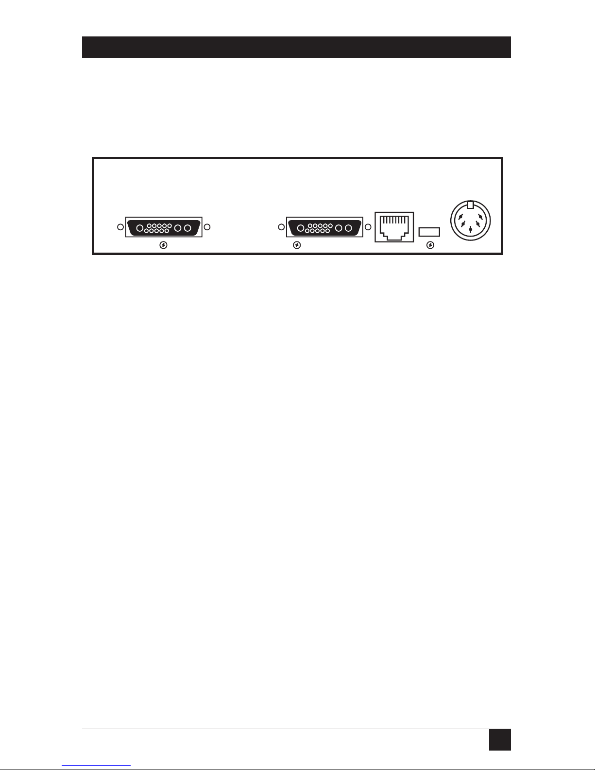
The ServSwitch Professor’s rear panel features two bus connectors, as well as an
RS-232 port, power inlet, and power switch, as illustrated in Figure 2-2 and
described below.
Figure 2-2. The rear panel of a ServSwitch Professor.
Panel Label Description
BUS IN, You’ll attach bus cable running to other ServSwitch Professors
BUS OUT to either or both of these 13W3 female ports. Remember that a
cable attached to one unit’s BUS IN port must be attached to
the BUS OUT port of the unit at the other end, and a cable
attached to one unit’s BUS OUT port must be attached to
another unit’s BUS IN port.
If a unit is the first station on the bus—that is, if there is
going to be (at least for now) a cable attached to the BUS OUT
port but not the BUS IN port—you’ll need to attach a
terminator to the BUS IN port. Similarly, if the unit is the last
station on the bus—if there is going to be a cable attached to the
BUS IN port but not the BUS OUT port—you’ll need to attach a
terminator to the BUS OUT port.
RS-232 RS-232 port reserved for factory diagnostics only. Do not attach
any of your equipment to this port.
POWER You’ll attach the output cord from the included power supply to
this 5-pin DIN female power inlet. This is not a keyboard input.
Input voltage is 17 VAC center-tapped.
[None] There is an unlabeled ON/OFF pushbutton just to the left of
the POWER inlet. Pressing it turns the Professor ON and OFF,
provided that the Professor’s power supply is properly attached to
the inlet.
BUS OUT BUS IN
POWER
17VAC CT
RS-232
Page 17
16
SERVSWITCH™ PROFESSOR
2.3.3 THEB
OTTOMPANEL
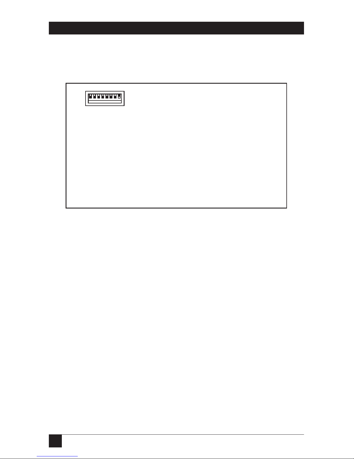
The ServSwitch Professor’s bottom panel features a configuration DIP switch, as
illustrated in Figure 2-3 and described below.
Figure 2-3. The bottom panel of a ServSwitch Professor.
Panel Label Description
[None] The setting of this 8-position configuration DIP switch
determines the bus address of the ServSwitch Professor
and the CPU attached to it. Each of the switch positions
corresponds to a binary multiple—from left to right,
position values are 128, 64, 32, 16, 8, 4, 2, and 1—so
addresses from 0 to 255 are available. Because address 0
is reserved for diagnostics and address 255 is reserved
for the instructor’s System Control Module and CPU,
Student Modules and CPUs can be set to any address
from 1 to 254.
Page 18

17
CHAPTER 2: Introduction
2.4 Cable Requirements
Many switches of this type have what seems like ten million connectors on their
rear panels: one for each CPU’s video cable, one for each keyboard cable, a third
for each mouse cable, and then there are the user-device cables—and don’t even
talk about the bus wiring running between the switches! Needless to say, the
potential for tangling or mismatching cables is high.
By contrast, you can connect the ServSwitch Professor to your CPUs with one
CPU Cable (also called a “CPU Adapter Cable”) for each CPU. This single cable
reaches the CPU’s video-output, keyboard, and mouse ports.
Likewise, you can connect the Professor to the shared monitor, keyboard and
mouse with a single User Cable (also called a “MKM Adapter Cable”).
Lastly, the communication between each pair of Professor units is carried on a
single high-quality bus cable. (You will also need to attach terminators to the first
and last devices on the bus.)
The exact variety or varieties of these cables that you’ll need will depend on the
equipment you are connecting for your application. Refer to Appendix B for the
available types of these cables and the corresponding product codes. Also refer to
Chapter 1 or the first Caution notice in Section 3.3.4 for information about
maximum cabling distances.
NOTES
SVGA (at higher resolutions) and XGA place special demands on
cabling that the regular CPU and User Cables typically cannot meet. For
these applications, you should use coaxial cables that can carry video
signals not only farther but also at
higher resolutions. See Appendix B
and the first Caution notice in Section 3.3.4.
Page 19

18
SERVSWITCH™ PROFESSOR
3. Installation
3.1 Quick Setup Guide
Figures 3-1 and 3-2 show a basic example of connecting a CPU, keyboard, monitor,
and mouse to the ServSwitch Professor, as well as interconnecting a set of
Professors with bus cables. Local-device connectors will vary depending on the
types of equipment you are installing.
Figure 3-1. Basic system setup (local-equipment side).
Figure 3-2. Basic system setup (bus side).
User
Cable
CPU
Cable
Bus Cable
Bus Cable
Bus Terminator
Bus Terminator
SERVSWITCH PROFESSOR (FRONT)
SERVSWITCH PROFESSORS (REAR)
Page 20
19
CHAPTER 3: Installation
3.2 Placement
It’s a good idea to put each ServSwitch Professor as close as possible to the CPU
and associated keyboard, monitor, and mouse that you want to attach to it. This is
because using short CPU and User Cables to run to your local devices is not only
neater and less expensive, but will also provide the best video quality to and from
those devices.
Typically you should leave the Professor’s front panel accessible in order to view
the STATUS and SEND LEDs, though once your whole system is installed you
probably won’t need to see these LEDs. As you place your units, also keep in mind
that the total length of bus cable in your system should not exceed 250 feet
(76.2 m), especially at high video resolutions.
3.3 The Installation Procedure
This section provides instructions for installing a single ServSwitch Professor
system; simply repeat these steps for each ServSwitch Professor, and your system
will be ready in no time. For an illustrated example of the elements of a basic
setup, see Figure 3-1 on the previous page.
3.3.1 S
ETTING THEUNIT’SBUSADDRESS
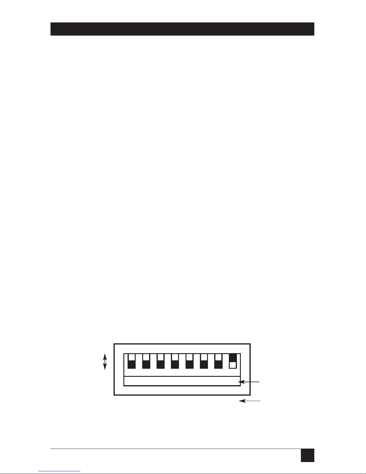
A ServSwitch Professor determines what its address is by reading the setting of its
bottom-mounted configuration DIP switch (show in Figure 3-3) at power-up. The
DIP switch represents a binary number: Each switch position corresponds to a
power of two that is added to the station’s address if the position is ON (UP) or not
added to the address if the position is OFF (DOWN). From left to right, the
positions correspond to 128, 64, 32, 16, 8, 4, 2, and 1. So, for example, if the
Professor station reads these positions as being set to UP DOWN DOWN UP UP
UP DOWN UP, it will add 128 + 16 + 8 + 4 + 1 and arrive at a total of 157, which it
will use as its address.
Figure 3-3. The configuration DIP switch.
1 23 45 678
128 64 32 14 8 4 2 1
ON
OFF
16
Switch position
Address = 1
Decimal value
Page 21

20
SERVSWITCH™ PROFESSOR
ServSwitch Professor System Control Modules (SCMs) should always be set to an
address of 255 (all DIP-switch positions up, the factory-default setting for SCMs),
and there should only be one SCM in a Professor system. Address 0 (zero, all
positions down) is reserved for diagnostic purposes. So Professor Student Modules
(STMs) should be set to addresses between 1 and 254. (The factory-default address
for STMs is “1.”) Here are the DIP-switch settings for the STM addresses up to 10:
• Address 1 = position 8 up;
• Address 2 = position 7 up;
• Address 3 = positions 7 and 8 up;
• Address 4 = position 6 up;
• Address 5 = positions 6 and 8 up;
• Address 6 = positions 6 and 7 up;
• Address 7 = positions 6, 7, and 8 up
• Address 8 = position 5 up;
• Address 9 = positions 5 and 8 up; and
• Address 10 = positions 5 and 7 up.
One note of caution: If you set two units to the same address, their LEDs will blink
rapidly when the system is powered up. But if you accidentally set the address of a
System Control Module to something other than 255 and set a Student Module to
address 255, the SCM will no longer recognize most commands, but the STM will.
So be very careful as you set this value.
3.3.2 R
ACKMOUNTING (OPTIONAL)
If you want to mount the ServSwitch Professor in a 19" rack, you will need a MiniSize Classic-Chassis ServSwitch Family Rackmount Kit (our product code SW727).
If you want to mount the ServSwitch Professor in a 23" or 24" rack, call Black Box
Technical Support for a quote on a special Kit. See Appendix C for more
information.
Page 22

21
CHAPTER 3: Installation
3.3.3 C
ONNECTING THEKEYBOARD
, M
ONITOR, ANDMOUSE
An included User Cable (also called a Monitor/Keyboard/Mouse [“MKM”] Adapter
Cable) connects your monitor, keyboard, and mouse to the ServSwitch Professor.
System Control Module Kits include one PS/2 style User Cable with 6-pin mini-DIN
keyboard and mouse connectors and one PC/AT style User Cable with a 5-pin DIN
mouse connector and a DB9 mouse connector; you can use the cable you need.
The Student Module Kits for PS/2 include just the PS/2 style cable. The Student
Module Kits for PC/AT include just the PC/AT style cable. If you lose this cable or
ever need another one or a longer one, it is also available separately; see Appendix B.
CAUTION!
Make very sure that the monitor, keyboard, and mouse you plan to use
can meet the demands of your application—see Section 4.1. Also, note
that the Professor doesn’t support most keyboard-line dongles.
If you order a longer replacement cable, be careful where and how you
run it; see the other Caution notice below.
Take these steps:
1. After you verify that the Professor is turned OFF, plug the DB25 male
connector of the User Cable into the DB25 female port labeled KEYBOARD/
MONITOR/MOUSE on the ServSwitch Professor’s front panel.
2. Plug the cables from your shared
monitor, keyboard, and mouse into the
corresponding connectors on the other
ends of the User Cable.
3.3.4 C
ONNECTING THE
CPU
An included CPU Cable runs from the ServSwitch Professor to the keyboard port,
mouse port, and video-output port of the CPU you want to directly attach to it.
System Control Module Kits include a PS/2 style CPU Cable with 6-pin mini-DIN
keyboard and mouse connectors, plus PC/AT keyboard (5-pin DIN) and mouse
(DB9) adapters. Student Module Kits for PS/2 include a PS/2 style CPU Cable but
not adapters. Student Module Kits for PC/AT include a dedicated PC/AT style
CPU Cable. If you lose this cable or an adapter, or ever need another one or a
longer one, they are also available separately; see Appendix B.
CAUTION!
Avoid routing longer replacement CPU or User Cables near fluorescent
lights, air-conditioning compressors, or machines that may create
electrical noise. Total length of original Serv cable (not including bus
cable) from any keyboard, monitor, and mouse to any given CPU should
not exceed 15 ft. (4.6 m). For typical equipment and
video resolutions,
length of coaxial cable should not exceed 20 ft. (6.1 m)
from a Professor
to any attached device (keyboard, monitor, mouse, or CPU). However,
we do provide coaxial cable in lengths up to 100 ft. (30.5 m), because
some CPUs can drive and receive keyboard and mouse signals at
greater distances than others. See Appendix B.
Page 23

22
SERVSWITCH™ PROFESSOR
Take these steps:
1. After you verify that the Professor is turned off and unplugged, plug the DB25
male connector of the CPU’s CPU Cable into the DB25 female COMPUTER
port on the Professor’s front panel.
2. Plug the CPU Cable’s video-, keyboard-, and mouse-port connectors into the
corresponding ports on the CPU. The CPU should be OFF when you do this;
the Switch will automatically adjust to the CPU’s keyboard mode when you
power up the CPU. Avoid plugging CPUs into the ServSwitch if they are
already ON; if you accidentally do so, see
Section 4.3.19 to make sure the
Professor is set for the proper keyboard mode.
CAUTION!
Do not attach docking stations for older models of the ThinkPad®or
other portable computers to the ServSwitch Professor. The Professor
currently supports only “stream mode” (continuous) mouse data, but
older ThinkPad models have to see “prompt mode” (burst-on-request)
mouse data. Some newer docking stations and some newer ThinkPad
models might work with the
Professor
, but determining whether a
particular unit will do so will probably require trial and error.
3.3.5 C
ONNECTING THEBUS
To interconnect ServSwitch Professors, you’ll use high-quality coaxial bus cables
with robust 13W3 male connectors. One such cable, 5 ft. (1.5 m) long, is included
with each Student Module Kit; if you ever need a replacement cable, or a longer
one, our product code is EHN275—specify your desired length. Also see
Appendix B.
You’ll also need two terminators, one for each of the unoccupied BUS ports that
mark the start and end of the bus. These terminators are included with your System
Control Module Kit; if you ever need a replacement, the product code is SW991.
How you hook up the bus to a given station depends on where along the bus the
station is:
• To connect the bus to the first station—most often the instructor’s System
Control Module, although that doesn’t have to be the case—attach a bus cable
to the first station’s BUS OUT port and run it to the second station’s BUS IN
port, then attach a bus terminator to the first station’s BUS IN port.
• To connect the bus to one of the middle stations, take the bus cable running
from the previous station’s BUS OUT port and attach it to this station’s BUS
IN port. Then run a cable from this station’s BUS OUT port to the next
station’s BUS IN port.
Page 24

23
CHAPTER 3: Installation
• To connect the bus to the last station, take the bus cable running from the
previous station’s BUS OUT port and attach it to this station’s BUS IN port,
then attach a bus terminator to the last station’s BUS OUT port.
Remember that cables must run from BUS OUT ports to BUS IN ports; never
connect cables from BUS IN to BUS IN or BUS OUT to BUS OUT. Also, do not
run bus cable in such a way that a ring is formed; your system will not work if you
do.
3.3.6 P
OWERING THEPROFESSOR
Once you’ve installed all of the equipment in your system, take these steps to
power up the system:
1. Making sure that all of the CPUs attached to the system are OFF (powered
down), take the output cord of each Professor’s power supply and plug its
5-pin DIN male connector into the 5-pin DIN female power inlet on the rear
panel of the Professor. Plug each power supply’s transformer (115 VAC) or
input cord (230 VAC) into a nearby AC-power outlet.
2. Push in the ON/OFF button on each Professor’s rear panel to power it up.
3. When you power up each Professor, its yellow status LED will light briefly and
go out. After a few seconds the status LED will flash irregularly as it talks to
the keyboard and mouse attached to the Professor. Then, if other ServSwitch
Professors are on the bus, the LED will flash at a steady one-second interval. If
it flashes at a faster rate, about three times per second, this indicates either a
hardware error or a duplicate address. See Chapter 5 for more information.
4. Power up the connected CPUs one by one, giving each one time to boot
completely before turning ON the next one. When the CPUs are powered up
after the Professors, the Professors will autodetect each CPU’s keyboard mode
and emulate all keyboard and mouse functions for automatic boot-up. (You
might want to issue a Keep Settings command after initial bootup, so that the
Professor saves the mode settings it has autodetected to nonvolatile memory.)
Page 25

24
SERVSWITCH™ PROFESSOR
3.3.7 T
ESTING THEPROFESSOR
Your ServSwitch Professor is now ready for operation using its default settings. To
take full advantage of the Professor’s features, refer to Chapter 4, which gives
detailed information about each of the Professor’s commands, describing its
application and giving the keyboard command sequence. For your convenience,
this information is summarized in Section 4.2. But here’s how to begin switching
immediately:
Find the keyboard template that you should have received with your unit, shown
in Figure 3-4. Put it over the upper function keys of your keyboard. The template
has commands listed at the top and station numbers at the bottom. Commands are
carried out by pressing and releasing the left [Ctrl] (control) key, pressing the
function key corresponding to the desired command, and pressing another
function key corresponding to the station(s) to which the command will apply. For
example:
• To view the screen of student #2: Press and release the left [Ctrl] key, then
press [F1] (view) and [F2] (CPU 2).
• To share the CPU of student #1: Press and release the left [Ctrl] key, then press
[F2] (share), and [F1] (CPU 1).
• To disable all students’ screens: Press and release the left [Ctrl] key, then press
[F6] (disable) and [F12] (all stations).
• To show the instructor’s screen to student #3: Press and release the left [Ctrl]
key, then press [F4] (show) and [F3] (station 3).
NOTES
The left [Ctrl] key starts all ServSwitch Professor commands—it cues
the Professor to look for commands from the keyboard. You then have
two seconds in which to start entering a valid command.
When you enter numeric commands, use only the numeral keys
located at the top of your alphanumeric keyboard. Numbers entered
from the numeric keypad to the right will not be recognized as valid
commands.
Figure 3-4. The Professor’s keyboard template.
F1 F2 F3 F4 F5 F6 F7 F8 F9 F10 F11 F12
View Share Control Show Enable Disable Freeze
Me All
1234 5678 910
XView XShare
Page 26

25
CHAPTER 4: Operation
4. Operation
The first part of this chapter, Section 4.1, gives you some guidelines that you
should follow to make sure your ServSwitch Professor works properly with your
equipment.
Section 4.2 summarizes the Professor’s keyboard commands, and Section 4.3
describes these commands in detail. Keep in mind that only the instructor’s System
Control Module (SCM, our product code KV780A) responds to commands;
Student Modules (STMs, our product codes KV781A and KV782A) ignore
commands.
NOTES
To start any ServSwitch Professor keyboard command, you must press
and release the left Control Key ([Ctrl]). Pressing and releasing [Ctrl]
cues the Professor to expect command characters from the keyboard.
You then have two seconds in which to start entering a valid command.
If no command is begun within two seconds or if an invalid command is
entered, the ServSwitch Professor aborts the command.
When entering commands that contain numbers or math symbols,
use only the numeral keys located at the top of your alphanumeric
keyboard. Numbers and symbols entered from the numeric keypad to
the right will not be recognized as valid.
Commands are not case-sensitive.
You must press the [Enter] key to complete any command that
requires a numeric operand.
4.1 Guidelines for Using the ServSwitch Professor with Your Equipment
4.1.1 CPU
S
Use only IBM PC/AT or PS/2 or 100% compatible machines. The ServSwitch
Professor does not support IBM PC/XT™ or compatible machines. It does not
support machines that output CGA or EGA video.
4.1.2 M
OUSE ANDKEYBOARD
When you power up your ServSwitch Professor system, make sure that your CPUs,
mice, and keyboards are properly cabled to each Professor. When you boot up
your CPUs, the Professors to which they are connected should already be ON. (You
should be able to freely disconnect and reconnect a mouse or keyboard from a
ServSwitch Professor while the Professor is ON, but if you experience problems
when you do this, issue the Reset command [CTRL] R—see Section 4.3.24).
Page 27

26
SERVSWITCH™ PROFESSOR
The ServSwitch Professor is designed to support IBM PC compatible 101-, 102-,
104-, or 105-key keyboards and IBM PC keyboard-scan modes 1, 2, and 3; it’s also
designed to work with PC-type CPUs/keyboards that use 5-pin DIN or 6-pin miniDIN keyboard connectors. Do not try to use the Professor with any keyboard that
uses nonstandard keys, connectors, or keyboard-scan modes.
Although the ServSwitch Professor resists minor transient surges that can be
caused by rapidly cycling power, certain keyboards are sensitive to such transients.
Because your shared keyboard’s power is provided by the Professor, wait at least
three seconds after powering down the Professor before powering it up again, or
the keyboard might not reset correctly.
The ServSwitch Professor supports several types of IBM PC type mice, including
PS/2 mice and RS-232 serial mice. The Professor does not support “wheel” mice
such as the Microsoft IntelliMouse
®
.
Because the ServSwitch Professor currently only supports “stream mode”
(continuous) mouse data but older IBM ThinkPad models have to handle mouse
data in “prompt mode” (burst-on-request), don’t try to attach any older ThinkPad
computers to the Professor, either directly or through docking stations. Some
newer models should work with the Professor, but there’s no good way to tell other
than by trial and error. (You can’t damage your equipment by trying—if you have
the wrong kind of ThinkPad, it just won’t work.)
Make sure that the CPUs attached to the system use only the generic Microsoft
mouse driver MOUSE.COM, version 4.0 at least and preferably version 9.01 or higher.
If you’re running Windows
®
3.x, this driver must be loaded in Windows as well as in
DOS. Do not, on any of your switched PC CPUs, run any programs or TSRs, or
enter any DOS commands, that change the settings of the mouse port after the
driver has been loaded.
When you first switch between CPUs, you might notice some variation in mouse
sensitivity (how far or fast the mouse moves) from CPU to CPU. This is normal. To
optimize mouse movement, adjust the sensitivity on each CPU according to your
individual preference. (This is usually handled through some kind of software
“control panel,” but the specifics vary depending on the operating system and on
the mouse driver.)
Page 28

27
CHAPTER 4: Operation
4.1.3 M
ONITOR
NOTE
At resolutions up to 1024 x 768, video quality will be excellent for most
Professor applications. At higher resolutions, however, it might not be
possible to avoid seeing some fuzziness on your monitors.
The ServSwitch Professor is designed to support standard VGA video, including VGA
monochrome (“page white”). It doesn’t support PCs that use CGA, EGA, or
proprietary VGA variants. If your PC’s manual doesn’t tell you whether or not the
PC uses standard VGA, consult with the PC’s or the video card’s manufacturer.
The
Professor
is also designed to support SVGA (Super VGA) video, although it
doesn’t handle higher resolutions very well without coaxial CPU and User Cables.
With coaxial cables, it will also support XGA.
Table 4-1 shows the marked decline in SVGA quality that can result if you try to use
original Serv type cables with higher resolutions or across longer distances. The
distances listed are total lengths of original Serv cable between a CPU and monitor;
they do not include any bus-cable length, because the bus cable can carry even
high-resolution video as far as 250 ft. (76.2 m) without significant degradation.
Table 4-1. Video quality vs. distance for original Serv cables.
Resolution
Distance
5' (1.5 m) 10' (3 m) 15' (4.6 m) 20' (6.1 m)
25' (7.6 m)
640 x 480 3333 3
800 x 600 noninterlaced 3332 2
1024 x 768 interlaced 3322 2
1024 x 768 noninterlaced 3222 2
1280 x 1024 interlaced 2111 1
1280 x 1024 noninterlaced 2111 1
Quality 3 = Near perfect; screen defects are not conspicuous
Quality 2 = Good to very good; images are clear; small reflections around text
lettering depending on the color; screen defects sometimes conspicuous
Quality 1 =
Fair to poor as distance increases; images run from slightly fuzzy to badly
smeared; text runs from fuzzy but readable to completely washed out
Page 29

28
SERVSWITCH™ PROFESSOR
By contrast, coaxial CPU and User Cables (required for XGA applications, and
recommended for most other applications) do much better at maintaining video
quality, as shown in Table 4-2. (For the meaning of quality numbers 3, 2, and 1, see
the bottom of the previous page.) The distances in the table are total lengths of
coaxial CPU and User Cable between the CPU and the monitor; as before, these
measurements do not include any bus-cable length.
Table 4-2. Video quality vs. distance for coaxial cables.
Resolution
Distance 10 ft. 20 ft. 30 ft. 50 ft. 75 ft. 100 ft. 150 ft. 200 ft.
(3 m) (6.1 m) (9.1 m) (15.2 m) (22.9 m) (30.5 m) (45.7 m) (61 m)
640 x 480 33 3 3 3 3 2 2
800 x 600 noninterl. 33 3 3 3 3 2 2
1024 x 768 interlaced 33 3 3 3 3 2 2
1024 x 768 noninterl. 33 3 3 2 2 2 1
1280 x 1024 interlaced 32 2 2 2 1 1 1
1280 x 1024 noninterl. 32 2 1 1 1 1 1
CAUTION!
Some CPUs can’t drive or receive keyboard and mouse signals across
longer runs of coaxial cable. Consult with the manufacturers of your
CPUs before installing this cable in lengths greater than 20 ft. (6.1 m).
For Professor-to-CPU or Professor-to-monitor runs over 100 feet (30.5 m), Station
Extenders or CAT5 KVM Extenders might be required. Call Black Box for
technical support to discuss this option.
Page 30

29
CHAPTER 4: Operation
4.2 Keyboard-Command Summary
Table 4-3 below and on the next three pages summarizes the commands that can be
sent to the ServSwitch Professor. To enter any command at the shared keyboard,
first press and release the left Control Key, represented by “[CTRL].” (This cues the
Professor to look for commands from that keyboard.) Then enter the command
followed by any arguments you wish to specify (the station number, for example).
Letter commands are not case-sensitive; they are all shown in uppercase for
clarity only.
When you enter numeric commands or arguments, use only the numbered keys
at the top of your alphanumeric keyboard. Numbers entered from the numeric
keypad to the right will not be recognized as valid commands.
All of these commands have a two-second timeout between characters. This
means that if you begin entering a command, but you stop for more than two
seconds at any time before you type the final character, the command is aborted
and the ServSwitch returns to normal operation. This keeps the Professor from
getting stuck waiting for you to finish the command.
The [CTRL] character is always passed through to the CPU, but cues the
Professor to accept commands. The command characters and operands, however,
are absorbed by the ServSwitch and are not sent to the CPU.
Many of these commands have factory-default values (see Appendix A) that can
be reloaded if your Professor becomes badly misconfigured; see Section 5.1.
Table 4-3. The ServSwitch’s keyboard commands.
*st = Station: Either any station number, [F1] through [F10] for student station 1 through 10,
[F11] for the instructor’s station, or [F12] for all students’ stations.
Disable keyboard and mouse at station.
[CTRL][F7]st*[ENTE
Freeze Station
Disable keyboard, mouse, and monitor at station.
[CTRL][F6]st*[ENTE
Disable Station
Enable keyboard, mouse, and monitor at station.
[CTRL][F5]st*[ENTE
Enable Station
Show instructor’s video to station.
[CTRL][F4]st*[ENTE
Show to Station
Take sole control of the CPU at station.
[CTRL][F3]st*[ENTE
Control Station
Share control of the CPU at station.
[CTRL][F2]st*[ENTE
Share Station
View CPU display and activity at station.
[CTRL][F1]st*[ENTE
View Station
DescriptionKeystroke Sequence
Command
Page 31

30
SERVSWITCH™ PROFESSOR
Table 4-3 (continued). The ServSwitch’s keyboard commands.
*st1, st2 = Stations 1 and 2: Either any station number, [F1] through [F10] for student
station 1 through 10, [F11] for the instructor’s station, or [F12] for all students’ stations.
Turns Scan mode OFF, giving the instructor viewonly access to the station being scanned at the
time the command is entered. Issuing the Keep
Settings command after you issue this command
will also turn power-on scanning OFF.
Note: Scan can also be stopped by entering a
station-selection command.
[CTRL] X
Scan OFF
Turns Scan mode ON, causing the ServSwitch to
start scanning sequentially from the current
station through the remaining stations until the
Maximum Scan Station is reached, and then
begin again at the Minimum Scan Station. If scan
is ON when you issue the Keep Settings
command, the unit will power up in scan mode.
[CTRL] S
Scan ON
Switches back to the station you were connected
to before you selected the current one (view-only
access). (Issuing this command repeatedly will
cause the Professor to switch back and forth
between two stations.)
[CTRL] [BACKSPACE]
Switch to the
Previously
Selected
Station
Switches to the previous station in sequence
(view-only access).
[CTRL] –
Switch to the
Previous
Station in
Numeric Order
Switches to the next station in sequence (viewonly access).
[CTRL] +
Switch to the
Next Station in
Numeric Order
View CPU display and activity at station xxx.
[CTRL] xxx [ENTER]
(xxx = a 1- to 3-digit
station number)
Select Station
Allow the student(s) at station1 to share control of
the CPU at station2.
[CTRL] [F10] st1*
[ENTER] st2*
XShare Station
with Station
Allow the student(s) at station1 to view the CPU
display and activity at station2.
[CTRL] [F9] st1*
[ENTER] st2*
XView Station
at Station
DescriptionKeystroke Sequence
Command
Page 32

31
CHAPTER 4: Operation
Table 4-3 (continued). The ServSwitch’s keyboard commands.
L4 gives a student station command-level
(instructor) access. L1 turns this off.
[CTRL] Lx [ENTER]
(x = 1 or 4)
Set Access
Level
Designates the current station as the one that
should be selected when the unit is powered up.
[CTRL] J
(with station selected)
Set Power-On
Station
Q1 turns on PS/2 to RS-232 mouse translation for
all user stations. Q2 turns on RS-232 to PS/2
translation for all stations. Q0 turns off mouse
translation for all stations (mouse type is
autodetected).
[CTRL] Qx [ENTER]
(x = 0, 1, or 2)
Set Mouse
Translation
Sets the keyboard typematic (automatic keyrepeat) function of the CPU attached to the
currently selected station.
[CTRL] Axxx [ENTER]
(xxx = a decimal value
from 0 to 127)
Set Keyboard
Typematic
Tells the Professor the keyboard mode expected
by the CPU attached to the selected station.
[CTRL] Mx [ENTER]
(x = 1, 2, or 3)
Set Keyboard
Mode
Sets the time of keyboard inactivity, in seconds,
that must elapse before another keyboard can
take control of the CPU attached to the selected
station. (Zero is an instant timeout; 255 disables
the timeout.)
[CTRL] Hxxx [ENTER]
(xxx = delay in seconds
from 0 to 255)
Set Keyboard
Timeout
Sets the time of inactivity, in seconds, after which
the Professor will blank the screen of the monitor
attached to the selected station. (The monitor is
reactivated when the mouse is moved or any key
on the shared keyboard is pressed.)
[CTRL] Vxxx [ENTER]
(xxx = delay in seconds
from 0 to 999)
Set Screen
Saver’s Delay
Time
Sets the highest-numbered station that will be
scanned and sequentially switched to.
[CTRL] >xxx [ENTER]
(xxx = station address)
Set Maximum
Scan Station
Sets the lowest-numbered station that will be
scanned and sequentially switched to.
[CTRL] <xxx [ENTER]
(xxx = station address)
Set Minimum
Scan Station
Sets the time, in seconds, that the ServSwitch will
pause at each station when scanning.
[CTRL] Txx [ENTER]
(xx = delay in seconds
from 1 to 15)
Set ScanDelay Time
Enter this command after you enter any of the
following ten commands (it saves new settings to
nonvolatile memory):
[CTRL] K
Keep Settings
DescriptionKeystroke Sequence
Command
Page 33

32
SERVSWITCH™ PROFESSOR
Table 4-3 (continued). The ServSwitch’s keyboard commands.
4.3 The Commands in Detail
IMPORTANT NOTE ABOUT ADDRESSES IN COMMANDS
Sections 4.3.1 through 4.3.9 discuss the commands that manipulate
station controls and displays. These commands share the
common
format, “[Ctrl] [function key] station_address [Enter] (station_address_2
[Enter]),”
where each “station_address” is the address of the station or
CPU for which the command is intended. The station address can be
designated with any of several different keystrokes or sets of
keystrokes:
• A one- to three-digit number (required for any station with an
address greater than 10)—as always, use the numeral keys from the
top of the keyboard, not from the numeric keypad;
• [F1] through [F10] for stations 1 through 10 respectively;
• [F11] for the instructor’s station (“Me”); or
• [F12] for all students’ stations (“All”).
4.3.1 V
IEWSTATION
The View Station command is used to observe a student’s screen. Issue the
command by pressing and releasing the left [Ctrl] key, pressing the [F1] key,
designating a station address (CPU number; see the Note above), and pressing
[Enter]. While you are in View mode, the System Control Module will discard all
non-command data coming from your keyboard and mouse.
Issuing the View Station command with a station address of All ([F12]) will turn
scan mode ON. Issuing the View Station command with a station address of Me
([F11]) will restore you (the instructor) to a normal connection with your own CPU.
Causes the ServSwitch to report the version of
ROM it is using. Issue this command if you are
asked to do so by a technical-support person.
[CTRL] I
Identify ROM
Causes the ServSwitch to send a null byte to the
CPU’s PS/2 mouse port. Issue this command to
correct the current CPU if it gets “out of sync” with
the PS/2 mouse (see Section 4.3.25).
[CTRL] N
Send Null Byte
Resets and enables the keyboard and mouse.
Issue this command to correct your keyboard or
mouse if one of them malfunctions or gets stuck.
[CTRL] R
Reset
DescriptionKeystroke Sequence
Command
Page 34

33
CHAPTER 4: Operation
4.3.2 S
HARESTATION
The Share Station command is used to interact with a student. Issue the command
by pressing and releasing the left [Ctrl] key, pressing the [F2] key, designating a
station address (CPU number; see the Note on the previous page), and pressing
[Enter]. All keyboard and mouse data is shared according to the keyboard-timeout
setting (see Section 4.3.18). If the student is using the keyboard and mouse when
you issue this command, the student will retain control until they stop using the
keyboard and mouse; once they do so, after the keyboard and mouse have
remained idle for the length of the student station’s keyboard timeout, you (the
instructor) can take control. You will retain control until you stop using the
keyboard and mouse for the duration of your station’s keyboard-timeout setting.
Issuing the Share Station command with a station address of All ([F12]) will turn
scan mode ON. Issuing the Share Station command with a station address of Me
([F11]) will restore you to a normal connection with your own CPU.
ServSwitch Professors that are sharing the same CPU will synchronize their
keyboard Lock states: Any of Num Lock, Caps Lock, or Scroll Lock that are ON at
the shared station’s keyboard when sharing begins will be turned ON at all sharing
keyboards; any that are OFF will be turned OFF. If anyone at any of the sharing
keyboards turns one of these Locks ON or OFF later, it will be turned ON or OFF
at all of the sharing keyboards.
4.3.3 C
ONTROLSTATION
The Control Station command is used to gain full control of a student’s computer.
Issue the command by pressing and releasing the left [Ctrl] key, pressing the [F3]
key, designating a station address (CPU number; see the Note on the previous
page), and pressing [Enter]. The student’s keyboard will be locked out and you
(the instructor) will have exclusive use of the student’s CPU.
Issuing the Control Station command with a station address of All ([F12]) will
turn scan mode ON. Issuing the Control Station command with a station address
of Me ([F11]) will restore you to a normal connection with your own CPU.
4.3.4 S
HOW TOSTATION
The Show to Station command is used to show the instructor’s screen to any or all
students. Issue the command by pressing and releasing the left [Ctrl] key, pressing
the [F4] key, designating a station address (CPU number; see the Note on the
previous page), and pressing [Enter]. You (the instructor) will retain control of
your own CPU; the student(s) will not be able to access it.
Issuing the Show to Station command with a station address of All ([F12]) will
send your screen to all students. Issuing the Show to Station command with a
station address of Me ([F11]) will stop sending your screen to other stations.
Page 35

34
SERVSWITCH™ PROFESSOR
4.3.5 E
NABLESTATION
The Enable Station command restores any or all students’ keyboards, mice, and
monitors to normal connections with their own CPUs after you (the instructor)
have restricted their access with the Disable Station or Freeze Station command
(see Section 4.3.6 or 4.3.7 respectively). Issue the command by pressing and
releasing the left [Ctrl] key, pressing the [F5] key, designating a station address
(CPU number; see the Note at the start of Section 4.3), and pressing [Enter].
Issuing the Enable Station command with a station address of All ([F12]) will
restore all students’ CPUs. Issuing the Enable Station command with a station
address of Me ([F11]) will restore you to a normal connection with your own CPU.
4.3.6 D
ISABLESTATION
The Disable Station command blanks any or all students’ screens and locks their
keyboards and mice. Issue the command by pressing and releasing the left [Ctrl]
key, pressing the [F6] key, designating a station address (CPU number; see the
Note at the start of Section 4.3), and pressing [Enter].
Issuing the Disable Station command with a station address of All ([F12]) will
disable all students’ CPUs. Issuing the Disable Station command with a station
address of Me ([F11]) will have no effect.
4.3.7 F
REEZESTATION
The Freeze Station command keeps any or all students’ screens active but locks
their keyboards and mice. Issue the command by pressing and releasing the left
[Ctrl] key, pressing the [F7] key, designating a station address (CPU number; see
the Note at the start of Section 4.3), and pressing [Enter].
Issuing the Freeze Station command with a station address of All ([F12]) will
freeze all students’ CPUs. Issuing the Freeze Station command with a station
address of Me ([F11]) will have no effect.
Page 36

35
CHAPTER 4: Operation
4.3.8 XV
IEWSTATION ATANOTHERSTATION
The XView Station at Another Station command is used to allow one or more
students to observe a fellow student’s screen. Issue the command by:
• pressing and releasing the left [Ctrl] key,
• pressing the [F9] key,
• designating the viewing station address (the address of the station[s] that will
be watching),
• pressing [Enter],
• designating the viewed address (the address of the station whose CPU activity
will be watched), and
• pressing [Enter] again.
Refer to the Note at the start of Section 4.3.
Issuing the XView Station at Another Station command with a viewing station
address of All ([F12]) will broadcast the viewed station’s screen to all students and
to you. Alternatively, you can issue several XView commands in succession to
designate only a subset of students to view the other student’s screen. For example,
[Ctrl][F9][F2][Enter][F3][Enter] followed by [Ctrl][F9][F4][Enter][F3][Enter]
shows station 3’s video to both station 2 and station 4. (However, the ServSwitch
Professor’s bus will only handle video data from a single source at any given time,
so although multiple students can view a single student’s video at the same time,
student A can’t view student B’s video while student C looks at student D’s video or
while you, the instructor, share control of student E’s CPU.)
While student stations are in XView mode, their Student Modules will discard all
of their keyboard and mouse data.
Issuing the XView Station at Another Station command with a viewing station
address of Me ([F11]) will cause the Professor system to behave just as if you had
entered the View Station command (see Section 4.3.1). Issuing the XView
command with a viewed station address of Me ([F11]) will cause the Professor
system to behave just as if you had entered the Show to Station command (see
Section 4.3.4). The Professor will ignore any XView command with a viewed station
address of All [F12].
To dissolve all XView relationships and return the Professor system to normal
operation (each student viewing and controlling his or her own CPU), send the
Enable All Stations ([Ctrl][F5][F12][Enter]) command (see Section 4.3.5).
Page 37

36
SERVSWITCH™ PROFESSOR
4.3.9 XS
HARESTATION WITHANOTHERSTATION
The XShare Station with Another Station command is used to allow one or more
students to share control of a CPU with one of their fellow students. Issue the
command by:
• pressing and releasing the left [Ctrl] key,
• pressing the [F10] key,
• designating the sharing station address (the address of the station[s] that will
be sharing a CPU that isn’t theirs),
• pressing [Enter],
• designating the shared address (the address of the station whose CPU will be
shared), and
• pressing [Enter] again.
Refer to the note at the start of Section 4.3.
When you issue the XShare command, the two or more stations involved share
keyboard and mouse control according to the keyboard-timeout setting (see
Section 4.3.18). (Note that the ServSwitch Professor system will not apply the
keyboard timeout of the shared station to all of the sharing students; rather, it will
use the different timeouts that you’ve individually set for each of those students’
stations.) If the student at the shared station is using the keyboard and mouse
when you issue this command, that student will retain control, but any of the other
sharing students can take control as soon as the student at the shared station stops
using the keyboard and mouse for the duration of their keyboard-timeout setting.
The student that then takes control will retain that control until they stop using the
keyboard and mouse for the duration of their keyboard-timeout setting.
Issuing the XShare Station with Another Station command with a viewing station
address of All ([F12]) will divide control of the shared station’s CPU among all
students and yourself. Alternatively, you can issue several XShare commands in
succession to designate only a subset of students to share control of the shared
station. For example, [Ctrl][F10][F6][Enter][F8][Enter] followed by [Ctrl][F9]
[F7][Enter][F8][Enter] will cause stations 6, 7, and 8 to share control of
student 8’s CPU. (However, the ServSwitch Professor’s bus will only handle video
data from a single source at any given time, so although multiple students can
share a single student’s CPU at the same time, student A can’t share student B’s
CPU while student C shares student D’s CPU or while you, the instructor, view
student E’s video.)
Page 38

37
CHAPTER 4: Operation
Issuing the XShare Station with Another Station command with a sharing station
address of Me ([F11]) will cause the Professor system to behave just as if you had
entered the Share Station command (see Section 4.3.2). Issuing the XShare
command with a shared station address of Me ([F11]) will actually allow students to
share control of your CPU. (Remember that even though students might be in
control of your CPU, your ServSwitch Professor System Control Module will always
respond instantly to your keyboard commands.)
The Professor will ignore any XShare command with a shared station address of
All ([F12]).
ServSwitch Professors that are sharing the same CPU will synchronize their
keyboard Lock states: Any of Num Lock, Caps Lock, or Scroll Lock that are ON at
the shared station’s keyboard when sharing begins will be turned ON at all sharing
keyboards; any that are OFF will be turned OFF. If anyone at any of the sharing
keyboards turns one of these Locks ON or OFF later, it will be turned ON or OFF
at all of the sharing keyboards.
To dissolve all XShare relationships and return the Professor system to normal
operation (each student viewing and controlling his or her own CPU), send the
Enable All Stations ([Ctrl][F5][F12][Enter]) command (see Section 4.3.5).
Page 39

38
SERVSWITCH™ PROFESSOR
4.3.10 S
ELECTSTATION
Instead of using the View, Share, or Control Station command to switch to a
student’s station, you can use this command to select any station directly. To do so,
press and release your keyboard’s left [Ctrl] key, type in the station address, and
press [Enter]. Do not try to use the function keys as a shortcut for stations 1
through 10—the Professor will interpret this as a different command instead. Also
remember to use the numbers located at the top of your keyboard; do not use the
numeric keypad.
This command will give you view-only access, as if you had entered a View Station
command (see Section 4.3.1). To gain shared or sole keyboard and mouse control,
you’ll need to issue a Share Station or Control Station command (see Section 4.3.2
or 4.3.3 respectively).
4.3.11 S
WITCH TO THENEXT ORPREVIOUSSTATION INNUMERICORDER
From the keyboard you can go forward or backward through the ServSwitch
Professor’s stations by selecting either the next or the previous station respectively.
To switch to the next station, press and release the left [Ctrl] key, then press the
plus key (the key at the top of the keyboard marked with [=] and [+]). To switch to
the previous station, press and release [Ctrl], then press the minus key (the key at
the top of the keyboard marked with [–] and [_]). The command is not casesensitive. Do not use the [+] and [–] keys on the keyboard’s numeric pad; the
Professor doesn’t recognize these.
These commands will give you view-only access, as if you had entered a View
Station command (see Section 4.3.1); to gain shared or sole keyboard and mouse
control, you’ll need to issue a Share Station or Control Station command (see
Section 4.3.2 or 4.3.3 respectively).
You can use these commands to switch only to those stations within the range
defined by the current Minimum Scan Station and Maximum Scan Station settings
(see Section 4.3.16.) If you issue a Next Numeric Station command when you’re
connected to the Maximum Scan Station (or to a higher-numbered station that
you’ve switched to by other means), the command will cause the Professor to “wrap
around” and switch to the Minimum Scan Station. Similarly, if you issue a Previous
Numeric Station command when you’re connected to the Minimum Scan Station
(or to a lower-numbered station that you’ve switched to by other means), the
command will cause the Professor to wrap in the opposite direction and switch to
the Maximum Scan Station. Lastly, the Professor will switch to the Minimum Scan
Station if you enter a Next Numeric Station command from any lower-numbered
station, and it will switch to the Maximum Scan Station if you enter a Previous
Numeric Station from any higher-numbered station.
Page 40

39
CHAPTER 4: Operation
4.3.12 S
WITCH TO THEPREVIOUSLYSELECTEDSTATION
You can use this command—which causes the Professor to switch back to the
station you had previously selected before selecting the station you’re currently
connected to—as a convenient method of switching back and forth between two
stations/CPUs. (This is especially useful when you have many CPUs, so that you
can avoid entering the multi-digit station numbers.) To switch to the previously
selected station, press and release the left [Ctrl] key, then press the [Backspace]
key. This will give you view-only access, as if you had entered a View Station
command (see Section 4.3.1); to gain shared or sole keyboard and mouse control,
you’ll need to issue a Share Station or Control Station command (see Section 4.3.2
or 4.3.3 respectively).
4.3.13 T
URNSCANMODE
ON OROFF
To start scanning (switching from station to station in a continuous rotation) from
the keyboard, press and release the left [Ctrl] key, then press [S]. The ServSwitch
Professor will begin scanning sequentially from your currently selected station. If
the currently selected station is within the range defined by the current Minimum
Scan Station and Maximum Scan Station settings (see Section 4.3.16.), the
Professor will scan through the higher-numbered stations until it reaches the
Maximum Scan Station, then begin again at the Minimum Scan Station. If the
currently selected station is outside that range, the Professor will switch to the
Minimum Scan Station first, then begin scanning.
As it scans, the Professor delays 1 to 15 seconds at each station. (This “Scan-Delay
Time” is user-selectable; see Section 4.3.15.) To stop scanning, press and release
[Ctrl], then press [X]; you can also stop a scan by entering a station-selection
command. (Remember that ServSwitch Professor letter commands are not casesensitive: You can enter upper- or lower-case letters.)
If you want the Professor to begin scanning immediately at power-up, issue the
Keep Settings ([Ctrl][K]) command (see the next section) while the unit is
scanning. In order to maintain this setting, however, you’ll need to be very careful,
because power-up scanning is just as easily turned off by ending a scan with
[Ctrl][X] and then issuing a Keep Settings command. This means that if you end a
scan with [Ctrl][X], then change a configuration setting and issue Keep Settings at
any time afterward before you scan again, power-on scanning will be turned off. To
maintain power-on-scanning as the ServSwitch Professor’s default state, you need
to do one of two things:
• Always end your scans by selecting a specific station with commands such as
View Station or Select Station.
• Never issue a Keep Settings command except while the Professor is scanning.
Page 41

40
SERVSWITCH™ PROFESSOR
4.3.14 K
EEPSETTINGS
The Keep Settings command causes all of the ServSwitch Professors in your system
to save their keyboard-selectable settings to their nonvolatile memory (NVRAM),
after which they become the new default (loaded at power-up) settings. To enter
the command, press and release the left [Ctrl] key, then type [K]. The ten
keyboard-selectable settings are described in the next nine sections.
4.3.15 SETS
CAN-DELAYTIME
Issue the Set Scan-Delay Time command to set the time, in seconds, that the
ServSwitch Professor will pause at each of the stations when it’s scanning them.
The factory-default setting is 5 seconds. To set a different delay time, press and
release the left [Ctrl] key, type [T] followed by the new delay time in seconds (1 to
15), and press [Enter]. Issue the Keep Settings command after you enter this
command.
4.3.16 SETM
INIMUM ANDMAXIMUMSCANSTATIONS
The Minimum and Maximum Scan Stations commands set the range of stations for
which scanning and numeric-order switching occurs. The default Minimum
Station is 1, the default Maximum Station is 16. To set the Minimum Station, press
and release the left [Ctrl] Key, type [<], enter the address of the new Minimum
Scan Station and press [Enter]. To set the Maximum Station, press and release the
left [Ctrl] Key, type [>], enter the address of the new Maximum Scan Station and
press [Enter]. Issue the Keep Settings command after you enter these commands
to save the settings.
Be careful not to accidentally set the Minimum Scan Station to an address higher
than the Maximum Scan Station; if you do, scanning will not work.
Page 42

41
CHAPTER 4: Operation
IMPORTANT NOTE FOR THE FOLLOWING SEVEN COMMANDS
Each of the seven commands described in the next seven sections
involves configuring stations. In order to configure any station, you
must first select that station with one of the station-selection commands
described in Sections 4.3.1 through 4.3.3 (View Station, Share Station, or
Control Station) or Sections 4.3.10 through 4.3.12 (Select Station, Switch
to Next Station, Switch to Previous Station, or Switch to Previously
Selected Station).
4.3.17 SETS
CREEN-SAVERINTERVAL
This feature reduces the wear on your monitor screens and provides security for
your system by blanking the screens when there has been no keyboard activity for a
specified length of time. (The ServSwitch Professor will also shut off all of its LEDs
when this “screen-saver mode” is active.) To set the screen-saver interval for a
station, first select that station (see the Note above), then press and release the left
[Ctrl] key, type [V] followed by the interval time in seconds (1 to 999, or 0 to
disable the screen saver), and press [Enter]. Issue the Keep Settings command
after you enter this command.
To reactivate the screen when it’s been blanked, press any key on the keyboard
or move the mouse. The default setting of this option is 0 (screen saver disabled).
4.3.18 SETK
EYBOARDTIMEOUT
This is a very powerful feature that controls access when two or more keyboards are
sharing a CPU. The setting of this time-interval value determines after what
amount of time a CPU becomes available for use by another keyboard.
Each ServSwitch Professor loads this timeout value (individually configurable for
each station) when it powers up, then reinitializes the value every time it detects
any activity on the keyboard or mouse that is currently controlling it. This process
is repeated any time you connect to a student’s CPU with the Share Station
command, or when you connect one or more students to your CPU or to another
student’s CPU with the XShare command: Your keyboard’s timeout or that of any
sharing student’s keyboard is loaded and is reinitialized every time any keyboard or
mouse activity occurs. If there is no keyboard or mouse activity for the length of
this time interval, the CPU becomes available for control by another station.
Each ServSwitch Professor can have a different timeout value set for its attached
keyboard, from 0 to 254 seconds (or 255 to disable the timeout—see the next
page). If a station’s CPU is being controlled by a user at another station, it is the
keyboard timeout of the user’s station that will be used to determine when the CPU
becomes available.
Page 43

42
SERVSWITCH™ PROFESSOR
If you set a station’s timeout for zero, the timeout becomes “instant”: The
keyboards of two stations each set for a zero timeout and connected to the same
CPU will appear to be sending data to the CPU simultaneously, because keystrokes
from either one will be accepted at any time. If you set a station’s timeout to 255,
the timeout becomes “infinite” (that is, the timeout is disabled): Any CPU
controlled by the keyboard on that station will not be released until either (a) the
user on that keyboard switches or is switched to another CPU, or (b) you change
the keyboard timeout of the user’s station.
The factory-default keyboard-timeout setting for each station is two seconds. To
set a different interval for a given station, first select that station (see the Note on
the previous page), then press and release the left Control Key, type [H], type in
the new keyboard-timeout interval in seconds, and press [Enter]. Then issue the
Keep Settings command to save the setting.
For example, to change the keyboard timeout on your instructor station (the
System Control Module) to 30 seconds, make sure you have your own station
selected, then type in [Ctrl][H][3][0][Enter], then type in [Ctrl][K][Enter]. Or,
to change the keyboard timeout on station 4 to 15 seconds, connect to station 4
with any of the station-selection commands—for example, View Station 4
([Ctrl][F1][F4])—then type in [Ctrl][H][1][5][Enter], then type in
[Ctrl][K][Enter].
Page 44

43
CHAPTER 4: Operation
4.3.19 SETK
EYBOARDMODE
Keyboard “modes” are electrical signaling protocols that determine how a powered
CPU and keyboard interact. A CPU and keyboard must use the same mode in
order to work with each other. Of the three standard keyboard modes currently in
use, mode number 2 is the one used by the vast majority of CPUs. It is also the
default state of all 101-key and PS/2 keyboards. Mode 1 is used primarily by certain
PS/2 CPUs. Mode 3 is used by RS/6000
®
CPUs, some other UNIX®based
computers, and certain specialized servers.
The ServSwitch Professor supports all three of these modes: As it receives signals
from any of the station keyboards, it sends them to the corresponding CPU by
emulating a keyboard of the appropriate mode for that CPU; as it receives signals
for one of the keyboards from the CPU, it sends them to that keyboard by
emulating a CPU of the appropriate mode.
Most CPUs that use keyboard mode 1 or 3 send a “mode command” to the
keyboard at power-up, to put the keyboard in the proper mode. If your CPU is a
mode 1 or mode 3 type, the Professor can use these commands to automatically
detect the CPU’s keyboard mode when you turn on the CPU after it has been
cabled to the Professor. However, the Professor doesn’t automatically save this
value; unless you send it a Keep Settings command, it will forget the mode it has
detected when it is turned off or loses power, then default to the most recently
saved setting when it’s powered up again. (For this reason, if you’re using mode 1
or mode 3 CPUs at any of your Professor stations, you will probably want to change
the default keyboard mode of those stations at installation time.)
The ServSwitch Professor’s factory-default keyboard-mode setting is mode 2.
Send the Set Keyboard Mode command to change the keyboard mode if:
• the CPU uses mode 2, but the Professor’s default keyboard-mode setting was
changed previously, or
• you don’t know which mode the CPU uses or the station is set for, but the
keyboard’s behavior makes you suspect that the station’s setting is wrong.
To set the keyboard mode at a particular station, first select that station (see the
Note above Section 4.3.17), then press and release the left [Ctrl] key, type [M],
and press the numeral key of the mode number ([1], [2], or [3]). After you enter
this command, enter the Keep Settings command to save the mode setting in
NVRAM, so that the new setting becomes the default value (preserved during
power-down and reloaded at power-up).
Page 45

44
SERVSWITCH™ PROFESSOR
4.3.20 SETK
EYBOARDTYPEMATIC
Most keyboards have an internal seven-bit “typematic” setting which governs the
way the keyboard responds when you hold a key down to force it to repeat. The five
“low” bits of this setting represent the rate at which the key repeats; the two “high”
bits represent the delay after you begin holding down the key before it begins to
repeat. Sometimes a keyboard’s typematic setting isn’t suitable for a given user or
for a given application.
To change the keyboard’s typematic setting at a particular station, first select that
station (see the Note above Section 4.3.17), then issue the Set Keyboard Typematic
command: Press and release the left Control key, type [A] followed by the desired
“typematic value,” and press [ENTER]. The “typematic value” is the decimal
equivalent of the binary seven-bit typematic setting: While the typematic setting =
delay bits + rate bits, the typematic value = decimal delay value + decimal rate value
(see Table 4-4 below and Table 4-5 on the next page). For example, to set the
shared keyboard to register a key 16 times per second after the key has been held
down for half a second (typematic value = 7 + 32 = 39), type in
[Ctrl][A][3][9][ENTER].
Issue the Keep Settings command after you enter this command.
Table 4-4. Typematic delay.
Decimal Binary Delay Before Key Repeats
Value Bit Values
0 00[xxxxx]
1
⁄4 second (250 ms)
32 01[xxxxx]
1
⁄2 second (500 ms)
64 10[xxxxx]
3
⁄4 second (750 ms)
96 11[xxxxx] 1 second (1000 ms)
Page 46

45
CHAPTER 4: Operation
Table 4-5. Typematic rate.
Decimal Binary Repeat Rate in
Value Bit Values Keys per Second
0[xx]00000 30
1[xx]00001 26.7
2[xx]00010 24
3[xx]00011 21.8
4[xx]00100 20
5[xx]00101 18.5
6[xx]00110 17.1
7[xx]00111 16
8[xx]01000 15
9[xx]01001 13.3
10 [xx]01010 12
11 [xx]01011 10.9
12 [xx]01100 10
13 [xx]01101 9.2
14 [xx]01110 8.6
15 [xx]01111 8
16 [xx]10000 7.5
17 [xx]10001 6.7
18 [xx]10010 6
19 [xx]10011 5.5
20 [xx]10100 5
21 [xx]10101 4.6
22 [xx]10110 4.3
23 [xx]10111 4
24 [xx]11000 3.7
25 [xx]11001 3.3
26 [xx]11010 3
27 [xx]11011 2.7
28 [xx]11100 2.5
29 [xx]11101 2.3
30 [xx]11110 2.1
31 [xx]11111 2
Page 47

46
SERVSWITCH™ PROFESSOR
4.3.21 SETM
OUSETRANSLATION
If the mice at all of your user stations are the same type (PS/2 or RS-232 serial) as
the mouse port of all of your CPUs, you can control the CPU from any station
without having to reconfigure the system at all. But if some of your mice are not
the same type as the CPU’s mouse port, you might need to turn mouse translation
on.
If your CPU is connected to the ServSwitch Professor through a serial mouse
port, but one or more of your stations have PS/2 mice, turn on PS/2 to RS-232
translation at those stations: First select one of the affected stations (see the Note
above Section 4.3.17), then press and release the left [Ctrl] key, type [Q][1], and
press [Enter].
If instead your CPU’s mouse port is PS/2 type but there are serial mice at any of
your stations, turn on RS-232 to PS/2 translation at those stations: First select one
of the affected stations (again, see the Note above Section 4.3.17), then press and
release the left [Ctrl] key, type [Q][2], and press [Enter].
To turn off mouse translation at a station, select that station (yet again, see the
Note above Section 4.3.17), press and release the left [Ctrl] key, type [Q][0], and
press [Enter]. (This is the default setting for mouse translation.)
After you change the mouse-translation setting, issue the Keep Settings
command.
4.3.22 SETP
OWER-ONSTATION
Sometimes you might want to set the ServSwitch Professor system to automatically
connect you to a station/CPU other than your own when the system is powered up.
If you do, you will be given view-only access to that station, as if you had entered
the View Station command.
To designate your Power-On Station, select that station (see the Note above
Section 4.3.17), press and release the left [Ctrl] key, then type [J]. Issue the Keep
Settings command after you enter this command.
Page 48

47
CHAPTER 4: Operation
4.3.23 SETA
CCESSLEVEL
We urge you to be very careful when using this command, because its main
purpose is to allow commands to be entered from a student station. Normally the
access level for student stations is “4” (commands ignored), while the access level
for the instructor station (the System Control Module) is “1” (commands
accepted). If a situation arises, however, in which you need the ServSwitch
Professor system to accept commands from a student station—for example, if you
need to go to a student station to troubleshoot a problem a student is having, or if
you have a responsible teaching assistant that you want to be able to issue
commands—use this command to change a student station’s access level to “1.”
To change a station’s access level to “1,” select that station (see the Note above
Section 4.3.17), press and release the left [Ctrl] key, then type [L][1][Enter]. To
change a station’s access level to “4,” select that station (see the Note above
Section 4.3.17), press and release the left [Ctrl] key, then type [L][4][Enter]. After
you change the access level, issue the Keep Settings command if you want this
setting to remain in effect until you change it.
Note that if you should accidentally set your instructor station to access level “4,”
you will not be able to enter commands from your station. This is easily solved,
however, even if you’ve since issued the Keep Settings command. Simply power
down your System Control Module, then power it back on; once it reads the “255”
address on its DIP switch, it will know it is an instructor station and will resume
accepting commands.
CAUTION!
Do not issue this command with any argument other than “1” or “4.”
This command’s other arguments are reserved for factory testing. If you
issue this command with some other argument, your ServSwitch
Professor system could—in fact, probably will—behave unpredictably.
Page 49

48
SERVSWITCH™ PROFESSOR
4.3.24 R
ESET
This command, along with the commands described in the next two sections, can
come in handy when certain problems arise. It will reboot your keyboard and
mouse without your having to power down the station or the system, and will also
re-enable PS/2 mouse communication if the selected CPU has previously disabled
it. (With current PCs and operating systems, this command shouldn’t be necessary,
but older CPUs running DOS or Windows might need it from time to time.) Issue
this command if (a) your keyboard gets stuck or begins behaving oddly, (b) you
need to send mouse data to the CPU, but it hasn’t enabled the mouse (this can
happen if you boot up the CPU while the ServSwitch Professor is off or
disconnected), or (c) while using a PS/2 type mouse, you unplug it, plug it back
in, then have problems. To issue the Reset command, press and release the left
[Ctrl] Key, then type [R].
If you’re using a PS/2 type mouse with a DOS or Windows 3.x CPU, don’t issue
this command if the CPU doesn’t have a mouse driver loaded—many such CPUs
will crash if you send them unexpected mouse data. (CPUs running UNIX or
Windows 95, 98, or NT don’t have this problem.) If your shared CPU is like this,
and you have chronic problems when you try to run applications that don’t use the
mouse but don’t disable the mouse either, take these precautions:
• If you never actually use the mouse with the CPU (as would probably be the
case if, for example, the CPU were a Novell
®
NetWare®file server), either don’t
plug the mouse strand of the CPU Cable into the CPU’s mouse port, or don’t
load a mouse driver at all. If you do use the mouse, are running Windows 3.x,
and sometimes exit to DOS, make sure you load a DOS mouse driver before
running WIndows.
• If you’ve loaded a DOS mouse driver and are going to use an application such
as NetWare that disables the PS/2 mouse, first REM out any statements in your
startup files (AUTOEXEC.BAT, etc.) that load the mouse driver, then reboot
the computer to remove the mouse driver from memory. (Having the mouse
driver unload itself doesn’t do the job.)
Page 50

49
CHAPTER 4: Operation
4.3.25 S
ENDNULLBYTE
(PS/2 T
YPEMICEONLY
)
Regular PS/2 type mice send control data to CPUs in three-byte increments.
Sometimes, because of electronic transients, unusual power-up effects, or plugging
and unplugging of cables from live equipment, an active CPU in a ServSwitch
Professor system can lose one or two bytes of this control information and get “out
of sync” with the mouse that’s controlling it. In this situation, the mouse might
seem to refuse to move the pointer or cursor, open windows for no reason, or
exhibit other strange behavior. To get the CPU back in sync, send this command
to tell the Professor to send a “null byte” to the CPU’s PS/2 mouse port (this has
no other effect than getting the CPU “caught up”). To issue the Send Null Byte
command, press and release the left [Ctrl] key, then type [N].
If the mouse still isn’t right after you issue this command, the CPU must have
been two bytes out of sync. Issuing the command again should do the trick.
The CPU will be thrown out of sync if it uses a PS/2 mouse and it’s in sync when
you issue this command. Issue this command two more times to get it back in sync
again. This command has no effect on serial mice, or on CPUs that are not
attached to your ServSwitch Professor system through a PS/2 mouse port.
If you have version 9.01 or higher of the Microsoft mouse driver, the CPU should
never get out of sync. Contact Microsoft if you are running DOS or any variety of
Windows and would like to upgrade your Microsoft mouse driver.
4.3.26 I
DENTIFY
ROM
Unfortunately, as with all complex equipment, problems might arise with your
ServSwitch Professor that require the assistance of technical-support personnel.
One of the things technicians might want to know when they attempt to diagnose
and correct your problem is the revision level of the ROM in each of your
ServSwitch Professors. This command causes the currently selected Professor
station to send the four-character “CVxy” ROM level—where “CV” is our factory
reference to the Professor, x is the major-revision number, and y is the minorrevision number—to the attached CPU as ASCII keyboard data; these characters
will be echoed back to the shared monitor if you are at some type of prompt. (You
must be at some kind of prompt or screen capable of displaying typed-in keyboard
characters, or you will not see the Professor’s response.) For example, if a station
responds with “CV35,” its ROM is programmed with version 3.5 of the ServSwitch
Professor firmware.
To issue the Identify ROM command, first select the station as described in the
Note above Section 4.3.17 (although with this command you’re getting
information about the unit rather than configuring it), then press and release the
left [Ctrl] key, then type [I].
Page 51

50
SERVSWITCH™ PROFESSOR
5. Troubleshooting
The first two sections of this chapter discuss things to try when problems arise in a
ServSwitch Professor system. If the trouble you’re having with the Professor is
something you haven’t seen before, or if the trouble seems minor, try the
procedures detailed in Section 5.1 before doing anything else. If the trouble is
chronic, see Section 5.2, which suggests possible causes and solutions to frequently
encountered problems. If those suggestions don’t help, Sections 5.3 and 5.4
discuss what’s involved in calling Black Box and shipping your Professor.
5.1 Restoring Factory-Default Settings
If you’re having difficulty with a ServSwitch Professor, something that sometimes
helps is resetting the Professor to its factory defaults. Follow these steps carefully:
1. Turn OFF (but do not unplug) the Professor and the CPU attached to it.
Disconnect that Professor from the bus cable and thus from the rest of your
ServSwitch Professor system.
2. Look at the configuration (address) DIP switch on the bottom of the
Professor. Set the Professor’s address to 0 (all DIP-switch positions DOWN).
3. Turn the Professor back ON. After it powers up, change its address to 1 (the
rightmost DIP-switch position UP, all other positions DOWN).
4. Wait two seconds, then turn the Professor back OFF again.
5. Set the Professor back to its normal address.
6. Reattach the bus cable and turn the Professor back ON. Turn the attached
CPU back on.
The unit should be restored to its factory-default settings. See Appendix A for a list
of these.
Now reconfigure the unit to your desired settings. If you’re still having difficulty,
refer to Section 5.2. If it doesn’t help you to solve your problem, call Black Box for
technical support.
Page 52

51
CHAPTER 5: Troubleshooting
5.2 Common Problems
A ServSwitch Professor’s STATUS LED continuously flashes three times per
second, and the Professor does not respond.
A. This Professor unit might be set to the same address as another unit in your
system. Check all of your units; if you find another one that also seems to be
disabled and whose STATUS LED is flashing the same way, change the address of
one of the units so that the addresses no longer match. See Section 3.3.1.
B. If this Professor unit is the only one in your system with this problem, the unit
has failed its self-test because one of its components is defective or has gone bad.
Call Black Box Technical Support to arrange to have it repaired (see Section 5.3).
A CPU connected to a ServSwitch Professor doesn’t boot, and you get a keyboard
or mouse error.
A. First make sure the ServSwitch Professor is plugged in and powered up.
B. If the Professor is ON, the keyboard and mouse settings for the attached CPU
might not be correct. Make sure which type of keyboard and mouse input the CPU
is expecting, then send an appropriate pair of Set Keyboard or Mouse commands
(see Section 4.3.19) to make sure those settings are correct.
C. If the configuration is OK but the problem persists, check your cables. Tighten
any loose connections. If the keyboard and mouse strands of either the CPU or
User Cable have been reversed, plug them into the proper ports.
D. If you don’t find a cable error, swap in different keyboards/mice one at a time.
If the problem goes away when you substitute a device, the old one might be bad.
E. If swapping input devices doesn’t help, swap your cables one at a time. If the
problem goes away when you substitute a cable, the old cable is probably defective.
F. If swapping cables doesn’t solve the problem, try connecting the CPU to either
(a) a known-good ServSwitch Professor or (b) a known-good keyboard and mouse.
If the CPU boots when it’s connected to a different unit, or directly to a keyboard
and mouse, the Professor it was connected to is probably defective.
G. If the CPU still doesn’t boot, the CPU’s keyboard or mouse port (or other
components) might be defective. (If the CPU’s Power LED doesn’t light, the fuse
on the CPU’s motherboard might be blown.) If you still have them, plug that CPU’s
original monitor, keyboard and mouse into it and try again. If the CPU doesn’t
boot with its original equipment, something in the CPU is defective; call the CPU’s
manufacturer. If the CPU does boot, there’s some unusual mismatch between that
CPU and the shared monitor, keyboard, or mouse; call Black Box Tech Support.
Page 53

52
SERVSWITCH™ PROFESSOR
You can’t select stations from the keyboard.
A. Can you do anything from the keyboard? If not, the keyboard segment of your
User Cable has probably come loose. Reconnect it.
B. The CPU on that station is probably busy (being used by someone else). Wait a
while and try again, or issue a Control Station command (see Section 4.3.3) to
attempt to take control of the CPU immediately.
C. The station you’re trying to switch to might be powered off, or the bus cable
might be disconnected at some point. Check the STATUS LED on your Professor
unit (the System Control Module): If it is not flashing at one-second intervals,
either there is something wrong with the bus cabling (disconnected, not
terminated properly, etc.) or there are currently no other powered units on the
bus.
D. The ServSwitch Professor might have lost power for less than three seconds.
(This can cause the keyboard to lock up.) Disconnect the keyboard and plug it
back in.
E. The keyboard mode that the currently selected station is set to output might not
match the mode that the CPU on that station expects. Issue the Set Keyboard
Mode command to change the station’s output keyboard mode (see
Section 4.3.19). Sometimes this situation can confuse the CPU or keyboard so
badly that it is necessary to reboot the CPU or to reset the keyboard by unplugging
it and plugging it back in.
F. For PS/2 type equipment, if the keyboard and mouse strands of either your User
Cable or the CPU Cable at the station you’re trying to switch to have been
reversed, plug them into the proper ports.
G. Check the station you’re trying to switch to and make sure that it is powered on
and that its CPU Cable is securely attached to it and to the computer.
H. You might be using the keyboard incorrectly. Make sure to use the left Control
key to start station-switching commands. Make sure to use the numeric keys at the
top of the keyboard rather than the numeric keypad when you type in station
numbers. Make sure to release the Control key before you start typing in a station
number. Make sure you don’t wait too long before you enter a station number.
Make sure you don’t accidentally hit keys such as [Shift], [Caps Lock], or [Alt].
Characters that you type come up wrong or missing.
The keyboard mode that the currently selected station is set for might not match
the mode that the CPU on that station expects. See item E under the “You can’t
select stations from the keyboard” problem above.
Page 54

53
CHAPTER 5: Troubleshooting
You can’t seem to scan or switch to certain stations at all.
Minimum Scan Station is set too high or Maximum Scan Station is set too low. Set
these parameters to exactly match the lowest- and highest-numbered stations,
respectively, that you want to be able to scan and switch to (see Section 4.3.16).
The Professor scans or switches to empty or nonexistent stations.
Minimum Scan Station is set too low or Maximum Scan Station is set too high. Set
these parameters to exactly match the lowest- and highest-numbered stations,
respectively, that you want to be able to scan and switch to (see Section 4.3.16).
Your mouse driver doesn’t load.
A. What type of mouse are you using? If it’s an RS-232 serial mouse, see steps B and
D. If it’s a PS/2 mouse, see steps C and D. If it’s a Microsoft BallPoint mouse, see
step D. The ServSwitch Professor does not support other types of mice.
B. RS-232 serial mouse: Make sure that you’re using the right COM port on the
computer, and that the mouse driver is looking for the correct port.
C. PS/2 mouse: To recognize the mouse, the CPU must be directly connected to it,
or indirectly connected to it through the ServSwitch Professor, at boot-up time.
Make sure that all cables are properly seated and that the Professor is ON, then
reboot the CPU.
D. Your mouse driver might be old or incompatible with your mouse. Try the latest
version of the Microsoft mouse driver.
You can’t access all the functions of your mouse.
A. What type of mouse is it? If it is any other type than those listed as being
supported in item A under the “Your mouse driver doesn’t load” problem, chances
are that the ServSwitch Professor doesn’t support it.
B. If your mouse is a Microsoft BallPoint, you need the latest version of the
Microsoft mouse driver.
C. If your mouse is a Logitech mouse, the Professor supports the two-button
models but not the three-button models. (The Professor does support most other
regular three-button PS/2 mice, not including “wheel” mice.)
Your PS/2 mouse gets out of sync.
Cabling might have been disturbed during mouse movement. Issue the Send Null
Byte command (see Section 4.3.25) once or twice to get the mouse back in sync.
You need the latest version of the Microsoft mouse driver to stop this from
happening.
Page 55

54
SERVSWITCH™ PROFESSOR
Your mouse doesn’t move the pointer/cursor.
A. What type of mouse is it? If it is any IBM PC type other than those listed as being
supported in item A under the “Your mouse driver doesn’t load” problem, chances
are that the ServSwitch Professor doesn’t support it.
B. The mouse might not be configured properly.
C. Your mouse must be connected to a powered ServSwitch Professor when the
attached CPU is booted and when applications that use the mouse are run. Try
exiting and re-entering your application; if this doesn’t work, issue the Reset
command (see Section 4.3.24).
Your monitor display is fuzzy.
A. Check the settings of your monitor, especially the sharpness control.
B. If you can’t solve the problem by changing the monitor settings, you might have
run cable too far. Total length of bus cable in your system should not be more than
250 ft. (76.2 m); total length of original CPU and User Cables between any station
and a CPU or monitor should not be more than 5 ft. (1.5 m); total length of
coaxial CPU and User Cables should not be more than 20 ft. (6.1 m) unless your
CPUs can drive keyboard and mouse signals strongly enough. If you are already
using coax CPU and User Cables, you might need to add Station Extenders or
CAT5 KVM Extenders; call Black Box for technical support. See Section 4.1.3 and
Appendix B.
Your video is not synchronized or is the wrong color.
A. Check the settings of your monitor, especially the sync or color controls.
B. Your monitor might not be capable of synching to the selected video resolution
or frequency (refresh rate). Try a lower resolution or frequency or a more
powerful monitor.
C. If the video problem is not centered on the monitor, check the video strands of
your cables. Tighten any loose connections.
D. If no cable connectors are loose, begin swapping your cables one at a time. If
the problem goes away when you substitute a cable, the old cable is probably
defective.
E. If swapping cables doesn’t solve the problem, try plugging the CPU into a
different ServSwitch Professor. If the problem goes away when the CPU is
connected to a different Professor, the unit you were using is probably defective.
Page 56

55
CHAPTER 5: Troubleshooting
Your video is OK in low-resolution mode, but you can’t get into high-resolution
mode.
A. If you’re using XGA, you must use coaxial cables (see Section 4.1.3 and
Appendix B).
B. Check your video driver or control panel. It might not be set up correctly for
your desired resolution.
One or more of your CPUs lock up when you load Windows 3.x.
The usual cause of this problem is that the affected CPUs are set to load a Logitech
or other type of mouse driver when Windows starts up. Set the CPU to load the
generic Microsoft mouse driver instead.
The ServSwitch Professor doesn’t work with your IBM ThinkPad.
The ServSwitch Professor supports only “stream mode” (continuous) mouse data.
It doesn’t support the “prompt mode” (burst-on-request) method for handling
mouse data that some older IBM ThinkPad models use, regardless of whether the
ThinkPad is connected to the Professor directly or through a docking station (and
see the next paragraph.
The ServSwitch Professor doesn’t work with your docking station.
The ServSwitch Professor does not support most docking stations for portable
computers.
The ServSwitch Professor doesn’t work with your dongle-protected software.
The ServSwitch Professor does not support most keyboard-line dongles (the
devices
required to be inserted into the keyboard line by some software for copy
protection).
Page 57

56
SERVSWITCH™ PROFESSOR
5.3 Calling Black Box
If you determine that your ServSwitch Professor is malfunctioning, do not attempt to
alter or repair the unit. It contains no user-serviceable parts. Contact Black Box
Technical Support at 724-746-5500.
Before you do, make a record of the history of the problem. We will be able to
provide more efficient and accurate assistance if you have a complete description,
including:
• the nature and duration of the problem.
• when the problem occurs.
• the components involved in the problem.
• any particular application that, when used, appears to create the problem or
make it worse.
• the results of any testing you’ve already done.
5.4 Shipping and Packaging
If you need to transport or ship your ServSwitch Professor:
• Package it carefully. We recommend that you use the original container.
• If you are shipping the Professor for repair, make sure you include its power
supply and the CPU and User Cables you’re using with it. If you are returning
the Professor, make sure you include everything you received with it. Before
you ship, contact Black Box to get a Return Authorization (RA) number.
Page 58

57
APPENDIX A: NVRAM Factory Defaults
Appendix A: NVRAM Factory Defaults
The table below and on the next page shows, for the ServSwitch Professor’s
saveable options, the default values stored in nonvolatile memory (NVRAM) when
the Professor is shipped from the factory. It also shows what commands or actions
can change these settings for the Professor’s current operating period, as well as
what commands or actions can save changed settings to NVRAM, so that they
become the new defaults.
[CTRL] K
Select station, then type
[CTRL] Hxxx [ENTER]
(xxx = any 1- to 3-digit number up
to 255; see Section 4.3.18)
2 seconds
Keyboard
Timeout
[CTRL] K
Select station, then type
[CTRL] Vxxx [ENTER]
(xxx = any 1- to 3-digit number;
see Section 4.3.17)
0 (screen saver disabled)
Screen Saver’s
Delay Time
[CTRL] K
Type [CTRL] >xxx [ENTER]
(xxx = any 1- to 3-digit number up
to 255; see Section 4.3.16)
Station 16Maximum
Scan Station
[CTRL] K
Type [CTRL] <xxx [ENTER]
(xxx = any 1- to 3-digit number up
to 255; see Section 4.3.16)
Station 1Minimum
Scan Station
[CTRL] K
Type [CTRL] Txx [ENTER]
(xx = any 1- or 2-digit number
from 1 to 15, time in seconds; see
Section 4.3.15)
5 secondsScan-Delay
Time
Changes
saved automatically
[CTRL] K while scanning to turn
on, [CTRL] K after ending scan
with [CTRL] X to turn OFF; see
Section 4.3.13
OFFPower-On
Scan
Can’t be
saved
Type [CTRL] S (to turn ON) or
[CTRL] X (to turn OFF); see
Section 4.3.13
OFFScan
Can’t be
saved
Select station, then press the
corresponding button on the
keyboard
Num Lock ON (fixed)Caps/Scroll/
Num Lock
To Save
Changes
To ChangeFactory-Default SettingOption
Page 59

58
SERVSWITCH™ PROFESSOR
[CTRL] K
Select station, then type
[CTRL] Lx [ENTER]
(x = 1 or 4; see Section 4.3.23)
1 for instructor (System
Control Module), 4 for
students (Student
Modules)
Access Level
[CTRL] K
Select station, then type [CTRL]
J
(see Section 4.3.22)
Each station connected
to its own CPU at powerup
Power-On
Station
[CTRL] K
Select station, then type
[CTRL] Qx [ENTER]
(x = 0, 1, or 2; see
Section 4.3.21)
OFF (mouse type
autodetected)
Mouse
Translation
[CTRL] K
Select station, then type
[CTRL] Axxx [ENTER]
(xxx = 0 to 127; see
Section 4.3.20)
43 (delay of 1⁄2 second,
rate of 10.9 characters
per second)
Keyboard
Typematic
[CTRL] K
Select station, then type
[CTRL] Mx [ENTER]
(x = 1, 2, or 3; see
Section 4.3.19)
Mode 2Keyboard
Mode
To Save
Changes
To ChangeFactory-Default SettingOption
Page 60

59
APPENDIX B: Cable Product Codes
Appendix B: Cable Product Codes
The table below and on the next page lists the product codes for all the types of
cables we currently offer for use with the ServSwitch Professor. The four digits that
follow the
dash in each product code indicate how long each cable is in feet
(one foot = 30.5 cm).
For most of these cables, xxx’s are shown in place of the last three digits of the
product code because the cables come in several stock lengths. For original
(standard) CPU and User Cables, these last three digits can be “001” (User Cables
only), “005,” “010,” or “020” for 1-foot (0.3-m), 5-foot (1.5-m), 10-foot (3-m) or
20-foot (6.1-m) cables respectively. For coaxial cables, these last three digits can be
“005,” “010,” “020,” “035,” “050,” “075,” or “100” for 5-foot (1.5-m), 10-foot (3-m),
20-foot (6.1-m), 35-foot (10.7-m), 50-foot (15.2-m), 75-foot (22.9-m), or 100-foot
(30.5-m) cables respectively.
The table also lists the product codes for the bus cables, Station Extenders, CAT5
KVM Extenders, etc.
Depending on your equipment and the video resolution
you’re
using, you might be able to use the Extenders to connect the Professor to a CPU or
user station as much as 1000 ft. (300 m) away.
If your ServSwitch Professor system has cabling requirements that can’t be met
by what you see here, call Black Box for a possible quote on custom cables or
adapters.
Standard User Cables:
Monitor Type Keyboard Type Mouse Type Product Code
(Connector on Cable) (Connector on Cable) (Connector on Cable)
VGA (HD15 female) IBM PC/AT (5-pin DIN female) Serial RS-232 (DB9 male) EHN052-0xxx
VGA (HD15 female) IBM PS/2 (6-pin mini-DIN female) PS/2 (6-pin mini-DIN female) EHN054-0xxx
Coaxial User Cables:
Monitor Type Keyboard Type Mouse Type Product Code
(Connector on Cable) (Connector on Cable) (Connector on Cable)
VGA (HD15 female) IBM PC/AT (5-pin DIN female) Serial RS-232 (DB9 male) EHN270-0xxx
VGA (HD15 female) IBM PS/2 (6-pin mini-DIN female) PS/2 (6-pin mini-DIN female) EHN283-0xxx
Page 61

60
SERVSWITCH™ PROFESSOR
Standard CPU Cables:
Video Type Keyboard Type Mouse Type Product Code
(Connector on Cable) (Connector on Cable) (Connector on Cable)
VGA (HD15 male) IBM PC/AT (5-pin DIN male) Serial RS-232 (DB9 female) EHN048-0xxx
VGA (HD15 male) IBM PS/2 (6-pin mini-DIN male) PS/2 (6-pin mini-DIN male) EHN051-0xxx
Coaxial CPU Cable:
Video Type Keyboard Type Mouse Type Product Code
(Connector on Cable) (Connector on Cable) (Connector on Cable)
VGA (HD15 male) IBM PS/2 and PC/AT PS/2 and serial RS-232 EHN282-0xxx
Coaxial Bus Cable: EHN275-0yyy, where “yyy” = 005, 025, 050, or 100
Station Extenders:
CPU to ServSwitch Professor (RS-232 Mouse): AC254A
ServSwitch Professor to Monitor, Keyboard, and Mouse (RS-232 Mouse): AC255A
CPU to ServSwitch Professor (PS/2 Style Mouse): AC258A
ServSwitch Professor to Monitor, Keyboard, and Mouse (PS/2 Style Mouse): AC259A
Station-Extender Cables: EHN250-0zzz, where “zzz” = 050, 100, 150, or 200
CAT5 KVM Extenders (Kits include local and remote Extender modules and extension cables to CPU):
Single-Access Kit (remote user station only): ACU1001A
Dual-Access Kit (local and remote user stations contend): ACU1009A
(Other CAT5 KVM Extender types are available. Call for more information.)
4-wire solid-core Category 5 UTP bulk cable, 1000-ft. (304.8-m) spool: EYN737A-1000
AT→→PS/2 Mouse Ghost (for PC/AT connections to the Extender): AC244A
Keyboard Adapter (for PC/AT connections to the Extender): FA212
Page 62

61
APPENDIX C: Rackmounting the ServSwitch Professor
Appendix C: Rackmounting the
ServSwitch Professor
If you’d like to mount any of your ServSwitch Professor units in a 19" rack, you’ll
need a 19" Rackmount Kit for Mini-Size Classic-Chassis ServSwitches (our product
code SW727). Each of these Kits consists of one rackmounting shelf and four
screws. To use one of these Kits to mount a ServSwitch Professor, take these steps,
referring to Figure C-1:
1. Remove the adhesive-backed rubber feet from the bottom of the Professor.
2. Place the Professor on the rackmount shelf.
3. The Professor and the shelf are pre-drilled for mounting. Using the
outermost pair of holes on either end of the shelf, screw the four selfthreading screws included with the Kit through the bottom of the shelf and
into the bottom of the Professor.
4. Mount the entire assembly in your rack using your own screws, bolts, or cage
nuts (not included).
If you need a Kit like this for a 23" or 24" rack, call Black Box Technical Support
for a special quote.
Figure C-1. Rackmounting the Professor.
Page 63

NOTES
Page 64

NOTES
Page 65

NOTES
 Loading...