

Page 1
KV7118SA
KV7148FA
FREE tech support 24 hours a day, 7 days a week: Call 724-746-5500 or fax 724-746-0746.
Mailing address: Black Box Corporation, 1000 Park Dr., Lawrence, PA 15055-1018
World-Wide Web: www.blackbox.com • E-mail: info@blackbox.com
© Copyright 2002. Black Box Corporation. All rights reserved.
Customer Support Information:
R
R
RR
AUGUST 1998
Page 2

1
THE SERVSWITCH™ FAMILY
Welcome to the ServSwitch
TM
Family!
Thank you for purchasing a BLACK BOX®ServSwitch™Brand KVM switch! We
appreciate your business, and we think you’ll appreciate the many ways that your
new ServSwitch keyboard/video/mouse switch will save you money, time, and
effort.
That’s because our ServSwitch family is all about breaking away from the
traditional, expensive model of computer management. You know, the one-sizefits-all-even-if-it-doesn’t model that says, “One computer gets one user station, no
more, no less.” Why not a single user station (monitor, keyboard, and mouse) for
multiple computers—even computers of different platforms? Why not a pair of
user stations, each of which can control multiple computers? Why not multiple
user stations for the same computer?
With our ServSwitch products, there’s no reason why not. We carry a broad line
of robust solutions for all these applications. Do you have just two PCs, and need
an economical alternative to keeping two monitors, keyboards, and mice on your
desk? Or do you need to share dozens of computers, including a mix of IBM
®
PC,
RS/6000
®
, Apple®Macintosh®, Sun Microsystems®, and SGI®compatibles among
multiple users with different access levels? Does your switch have to sit solidly on a
worktable and use regular everyday cables? Or does it have to be mounted in an
equipment rack and use convenient many-to-one cables? No matter how large or
small your setup is, no matter how simple or how complex, we’re confident we
have a ServSwitch system that’s just right for you.
The ServSwitch
™
family from Black Box—the one-stop answer for all your KVM-
switching needs!
*
This manual will tell you all about your new ServSwitch Elite™ unit, including
how to install, operate, and troubleshoot it. For an introduction to the ServSwitch
Elite, see Chapter 2. The ServSwitch Elite product codes covered in this manual
are:
KV7118SA
KV7148FA
This manual also includes information about the acessories with these product
codes (each comes with its own installation guide if ordered separately):
KV7150A RMK19E
KV7160A RMK19E4
KV7170A
Page 3

2
SERVSWITCH ELITE™
TRADEMARKS USED IN THIS MANUAL
Apple and Macintosh are registered trademarks of Apple Computer, Inc.
Compaq is a registered trademark of Compaq Computer Corporation.
Hewlett-Packard, HP, and HP9000 are registered trademarks of Hewlett-Packard.
IBM, PC/AT, PS/2, RISC System/6000, and RS/6000 are registered trademarks
of International Business Machines Corporation.
Logitech is a trademark of Logitech, Inc.
IntelliMouse and Microsoft are either registered tradmark or trademarks,
of Microsoft Corporation in the United States and/or other countries.
SGI is a registered trademark of Silicon Graphics, Inc.
Sun Microsystems is a registered trademark of Sun Microsystems, Inc.
Any other trademarks mentioned in this manual are acknowledged to be the property of the
trademark owners.
DISCLAIMER
The information in this manual is subject to change without notice. The
manufacturer shall not be liable for technical or editorial errors or omissions
contained herein; nor is it liable for incidental or consequential damages resulting
from the furnishing, performance, or use of this material.
Page 4

3
FCC/IC STATEMENTS
FEDERAL COMMUNICATIONS COMMISSION
AND
CANADIAN DEPARTMENT OF COMMUNICATIONS
RADIO FREQUENCY INTERFERENCE STATEMENTS
This equipment generates, uses, and can radiate radio frequency energy and if not
installed and used properly, that is, in strict accordance with the manufacturer’s
instructions, may cause interference to radio communication. It has been tested
and found to comply with the limits for a Class A computing device in accordance
with the specifications in Subpart B of Part 15 of FCC rules, which are designed to
provide reasonable protection against such interference when the equipment is
operated in a commercial environment. Operation of this equipment in a
residential area is likely to cause interference, in which case the user at his own
expense will be required to take whatever measures may be necessary to correct the
interference.
Changes or modifications not expressly approved by the party responsible for
compliance could void the user’s authority to operate the equipment.
Shielded cables must be used with this equipment to maintain compliance with
radio frequency energy emission regulations and ensure a suitably high level of
immunity to electromagnetic disturbances.
This digital apparatus does not exceed the Class A limits for radio noise emission from digital
apparatus set out in the Radio Interference Regulation of the Canadian Department of
Communications.
Le présent appareil numérique n’émet pas de bruits radioélectriques dépassant les limites
applicables aux appareils numériques de la classe A prescrites dans le Règlement sur le
brouillage radioélectrique publié par le ministère des Communications du Canada.
Page 5

4
SERVSWITCH ELITE™
BZT COMPLIANCE STATEMENT
BZT HINWEIS
Hiermit wird bescheinigt, daß dieses Gerät in Übereinstimmung mit den
Bestimmugen der BMPT-AmtsblVfg 243/1991 funk-enstört ist. Der
vorschriftsmäßige Betrieb mancher Gerät (z.B. Meßsender) kann allerdings
gewissen Einschränkungen unterliegen. Beachten Sie deshalb die Hinweise in der
Bedienungsanleitung.
Dem Bundesamt für Zulassungen in der Telekommunikation wurde das
Inverkehrbringen dieses Geräts angezeigt und die Berechtigung zur Überprüfung
der Serie auf die Einhaltung der Bestimmugen eingeräumt.
Page 6

5
NOM STATEMENT
NORMAS OFICIALES MEXICANAS (NOM)
ELECTRICAL SAFETY STATEMENT
INSTRUCCIONES DE SEGURIDAD
1. Todas las instrucciones de seguridad y operación deberán ser leídas antes de
que el aparato eléctrico sea operado.
2. Las instrucciones de seguridad y operación deberán ser guardadas para
referencia futura.
3. Todas las advertencias en el aparato eléctrico y en sus instrucciones de
operación deben ser respetadas.
4. Todas las instrucciones de operación y uso deben ser seguidas.
5. El aparato eléctrico no deberá ser usado cerca del agua—por ejemplo, cerca
de la tina de baño, lavabo, sótano mojado o cerca de una alberca, etc..
6. El aparato eléctrico debe ser usado únicamente con carritos o pedestales que
sean recomendados por el fabricante.
7. El aparato eléctrico debe ser montado a la pared o al techo sólo como sea
recomendado por el fabricante.
8. Servicio—El usuario no debe intentar dar servicio al equipo eléctrico más allá
a lo descrito en las instrucciones de operación. Todo otro servicio deberá ser
referido a personal de servicio calificado.
9. El aparato eléctrico debe ser situado de tal manera que su posición no
interfiera su uso. La colocación del aparato eléctrico sobre una cama, sofá,
alfombra o superficie similar puede bloquea la ventilación, no se debe colocar
en libreros o gabinetes que impidan el flujo de aire por los orificios de
ventilación.
10. El equipo eléctrico deber ser situado fuera del alcance de fuentes de calor
como radiadores, registros de calor, estufas u otros aparatos (incluyendo
amplificadores) que producen calor.
11. El aparato eléctrico deberá ser connectado a una fuente de poder sólo del
tipo descrito en el instructivo de operación, o como se indique en el aparato.
Page 7

6
SERVSWITCH ELITE™
12. Precaución debe ser tomada de tal manera que la tierra fisica y la polarización
del equipo no sea eliminada.
13. Los cables de la fuente de poder deben ser guiados de tal manera que no
sean pisados ni pellizcados por objetos colocados sobre o contra ellos,
poniendo particular atención a los contactos y receptáculos donde salen del
aparato.
14. El equipo eléctrico debe ser limpiado únicamente de acuerdo a las
recomendaciones del fabricante.
15. En caso de existir, una antena externa deberá ser localizada lejos de las lineas
de energia.
16. El cable de corriente deberá ser desconectado del cuando el equipo no sea
usado por un largo periodo de tiempo.
17. Cuidado debe ser tomado de tal manera que objectos liquidos no sean
derramados sobre la cubierta u orificios de ventilación.
18. Servicio por personal calificado deberá ser provisto cuando:
A: El cable de poder o el contacto ha sido dañado; u
B: Objectos han caído o líquido ha sido derramado dentro del aparato; o
C: El aparato ha sido expuesto a la lluvia; o
D: El aparato parece no operar normalmente o muestra un cambio en su
desempeño; o
E: El aparato ha sido tirado o su cubierta ha sido dañada.
Page 8

7
TABLE OF CONTENTS
Contents
Chapter Page
1. Specifications ............................................................................................. 9
2. Introduction ............................................................................................. 11
2.1 Overview ............................................................................................ 11
2.2 Key Features ...................................................................................... 12
2.2.1 Flexibility and Versatility ........................................................ 12
2.2.2 Improved Video Quality ......................................................... 12
2.2.3 Ease of Use and Maintenance ................................................ 12
2.3 Possible System Configurations ........................................................ 13
2.3.1 Single ServSwitch Elite Systems .............................................. 13
2.3.2 Multiple ServSwitch Elite Systems .......................................... 14
3. Installation ................................................................................................ 17
3.1 Unpacking the Switch/The Complete Package .............................. 17
3.2 Setting DIP Switch F (4x8 Model Only) .......................................... 17
3.3 Rackmounting Switches (Optional) ................................................ 18
3.4 The Installation Procedure .............................................................. 20
3.4.1 Placing the Unpowered Switches ........................................... 20
3.4.2 Cascading Switches (Optional) .............................................. 20
3.4.3 Connecting the Console Equipment ..................................... 23
3.4.4 Connecting the Computers .................................................... 26
3.4.5 Connecting the Power ............................................................ 27
3.5 Initial Power-Up: Turning On the System ....................................... 28
4. Operation and Configuration ................................................................. 30
4.1 Basic Operation ................................................................................. 31
4.1.1 Switching Between Computers ............................................... 31
4.1.2 Checking Port/Computer Status ........................................... 35
4.2 Higher-Level Operation and Configuration:
The FUNCTIONS Menu ............................................................. 36
4.2.1 Scanning Computers in the System ....................................... 37
4.2.2 Displaying Version Information and Device Settings ........... 38
4.2.3 Saving the Hardware Configuration ...................................... 39
4.2.4 Resetting the Mouse and Keyboard Ports .............................. 39
4.2.5 Using Broadcast Mode (Single-User Model Only) ............... 40
4.2.6 Setting a Scan Pattern ............................................................. 43
Page 9

8
SERVSWITCH ELITE™
Contents (continued)
Chapter Page
4. Operation and Configuration (continued)
4.2 Higher-Level Operation and Configuration:
The FUNCTIONS Menu (continued)
4.2.7 Assigning Unique Names to the Computers and
Slaves in the System ......................................................... 45
4.2.8 Changing the Menu Attributes ............................................ 47
4.2.9 Changing the Attributes of the Ststus Flag .......................... 50
4.2.10 Assigning Specific Device Types .......................................... 52
4.2.11 Setting Security Options ....................................................... 53
4.3 Resetting the ServSwitch Elite .......................................................... 56
4.4 Making Connections Under Power ................................................. 56
4.5 Power-Outage Recovery .................................................................... 56
5. Troubleshooting ...................................................................................... 57
6.1 Common Problems ........................................................................... 57
6.2 Calling Black Box .............................................................................. 59
6.3 Shipping and Packaging ................................................................... 59
Appendix A: Keyboard Commands for the On-Screen Display ................... 60
Appendix B: Upgrading the Firmware .......................................................... 61
Appendix C: RS/6000 Handling ................................................................... 63
Appendix D: Interface Pinouts ...................................................................... 64
D.1 IBM PC/AT Compatible Keyboard .................................................. 64
D.2 IBM PC/AT Compatible Serial Mouse ............................................ 64
D.3 IBM PS/2 Compatible Keyboard and Mouse .................................. 65
D.4 IBM Video Graphics Array (VGA),
Super Video Graphics Array (SVGA) ......................................... 66
Page 10

9
CHAPTER 1: Specifications
1. Specifications
Compliance — EMI/RFI: CE; CISPER-A; FCC Part 15 Subpart B Class A,
DOC Class/MDC classe A;
Electrical Safety: UL®1950, cUL, TUV/GS, EN 60950
Standards — VGA, SVGA, and XGA video
Compatibility — Video: VGA, SVGA, XGA, GTX, or GTX1XX; also
IBM RS/6000 and HP9000, although RS/6000 requires
special cabling and RS/6000 and HP9000 sync-ongreen applications require video adapters;
Keyboard: IBM PC/AT or PS/2 compatible (connecting
a PC/AT keyboard requires an adapter such as our
product code FA211);
Mouse: IBM PS/2 compatible two-button, Microsoft
IntelliMouse, or Logitech™ PS/2 compatible 2- or
3-button
Interfaces — Video: VGA;
Keyboard and mouse: IBM PS/2 compatible
Resolution — Up to 1024 x 768 noninterlaced
Maximum
Distance — 12 ft. (3.6 m) of extension cabling to any attached
keyboard, monitor, and mouse;
50 ft. (15.2 m) of extension cabling to any attached CPU
or cascaded ServSwitch Elite unit
User Controls — Keyboard/on-screen-menu commands;
(1) Rear-mounted rocker switch for power;
(1) Rear-mounted reset pushbutton;
KV7148FA only: (1) Internal DIP switch for port-
contention handling
Indicators — On-screen windows and on-screen status-flag box
Page 11

10
SERVSWITCH ELITE™
Connectors — All rear-mounted:
(1) RJ-45 female AUX connector;
(1) IEC 320 male power inlet;
(8) sets of:
(1) HD15 female to CPU’s video port;
(2) 6-pin mini-DIN female:
(1) to CPU’s keyboard port,
(1) to CPU’s mouse port;
For each computer port:
(1) HD15 female to monitor;
(2) 6-pin mini-DIN female:
(1) to keyboard, (1) to mouse;
KV7118SA: (1) set;
KV7148FA: (4) sets
MTBF — 100,000 hours (calculated)
Temperature
Tolerance — 50 to 104˚F (10 to 40˚C)
Humidity
Tolerance — 5 to 90% noncondensing
Enclosure — Cold-rolled steel
Power — Input: 100 to 120 VAC or 200 to 240 VAC at 50 to 60 Hz
from utility-power outlet, through detachable power
cord and IEC 320 male inlet;
Consumption: 30 watts maximum
Size — KV7118SA:
1.8"H (1U) x 17"W x 10.8"D (4.4 x 43.2 x 27.4 cm);
KV7148FA:
3.5"H (2U) x 17"W x 10.8"D (8.9 x 43.2 x 27.4 cm)
Weight — KV7118SA: 9.1 lb. (4.1 kg);
KV7148FA: 10.3 lb. (4.6 kg)
Page 12

11
CHAPTER 2: Introductiom
2. Introduction
2.1 Overview
The ServSwitch Elite is another great space- and effort-saving solution in the
ServSwitch™ family of KVM switches from Black Box. It is 100% pin-for-pin
compatible with the current generation of KVM switches by Compaq
®
and Hewlett-
Packard
®
, so it’s just right for adding to your existing Compaq or HP®environment.
It’s also “modular” in that it can be configured and installed in different
quantities and locations to suit the switching needs of a particular system. You can
use multiple Switches to expand the system and connect user consoles to any of up
to 64 computers.
With one single-user (our product code KV7118SA) ServSwitch Elite, users at a
single user console (monitor, keyboard, and mouse station) can access any of as
many as eight IBM
®
PC, IBM RISC System/6000®(RS/6000®), or HP9000
®
compatible computers. With one 4x8 (KV7148FA) model, users at up to four user
consoles can access any of up to eight such computers. Both versions are enclosed
in space-efficient cases to save space on your desktop or in your rack: 1U (1.8",
4.4 cm) high for the single-user model, 2U (3.5", 8.9 cm) high for the 4x8 model.
And you can attach as many as eight “slave” units of either version to a “master”
unit of either version to create a cascaded system with a capacity for 64 computers.
Switching between (also called “selecting”) computers is accomplished by typing
a command at the keyboard. The selected computer receives characters typed at
the keyboard and displays its video output on your monitor. You can use the mouse
(which is optional) to interact with the graphic interface that the selected
computer displays on the monitor. The ServSwitch Elite works independently of
the attached computers’ operating systems, so it doesn’t matter if the computers
are running different operating systems.
Page 13

12
SERVSWITCH ELITE™
2.2 Key Features
2.2.1 F
LEXIBILITY AND
V
ERSATILITY
The ServSwitch Elite is compatible with several types of keyboards and mice,
including:
• Industry-standard IBM PS/2
®
compatible keyboards and mice, including
Logitech™ 2- and 3-button types;
• RS/6000 and HP9000 keyboards and mice;
• Microsoft
®
IntelliMouse®compatible mice;
• With the proper interface adapters, IBM PC/AT
®
compatible keyboards and
serial mice (serial mice must be clearly identified as “mouse-port compatible”).
The Switch is also compatible with computers that have any of several major types
of peripheral-I/O ports, including:
• PS/2 compatible (including RS/6000 and HP9000) keyboard and mouse
ports, or,
• Through our PC/AT Serial Mouse Converter Kit (KV7150A), PC/AT keyboard
ports and RS-232 serial mouse ports.
2.2.2 I
MPROVEDVIDEOQUALITY
The ServSwitch Elite supports standard display adapters and high-resolution video.
Specifically, they support analog VGA, SVGA, and XGA video, as well as—with the
RS/6000 (KV7160A) or HP9000 (KV7170A) Converter Kit respectively—RS/6000
or HP9000 video. The Switch can drive video at a maximum resolution of 1024 by
768 pixels across a 50-foot (15.2-m) video cable.
2.2.3 E
ASE OFUSE ANDMAINTENANCE
• On-Screen Display
The Switch’s on-screen menus display a variety of system-related information
on any console monitor, including power-up test data and configuration
menus.
• Programmable Scanning
Scanning lets you observe system performance by sequentially displaying the
video from any or all of the computers in the system on your monitor.
Programable scanning allows you to select which computers to include and to
specify the duration of the connection.
Page 14

13
CHAPTER 2: Introductiom
• Configuration NVRAM.
The ServSwitch Elite uses nonvolatile RAM (NVRAM), which makes it easy to
configure the Switch using commands entered from your keyboard. The
NVRAM stores the resulting configuration until you decide to change the
configuration settings again, even if the Switch is turned off or unplugged.
• External Reset Switch
If keyboard or mouse communication is disrupted, you can push this button to
reinitialize the keyboard and mouse without turning the Switch off.
• Password Protection
Protects network resources by locking the keyboard and monitor.
• Broadcasting
Sends keyboard and/or mouse input to multiple computers simultaneously,
• Remote Keypad (optional, special quote)
A remote keypad for the ServSwitch Elite, consisting of a handheld controller
attached to a 2-ft. (0.6-m) cable terminated with an RJ-45 plug, is available on a
special-quote basis. When you connect it to the Switch’s rear-panel AUX
connector, it can take the place of the keyboard for the purpose of selecting
computers on the Switch. Contact Black Box Technical Support for more
information.
2.3 Possible System Configurations
ServSwitch Elites can be used in various system configurations to meet the needs of
organizations operating computer networks of various sizes:
• Single Servswitch Elites can be used to connect up to eight computers
• Multiple Switches can be cascaded to connect up to 64 computers
2.3.1 S
INGLESERVSWITCHELITESYSTEMS
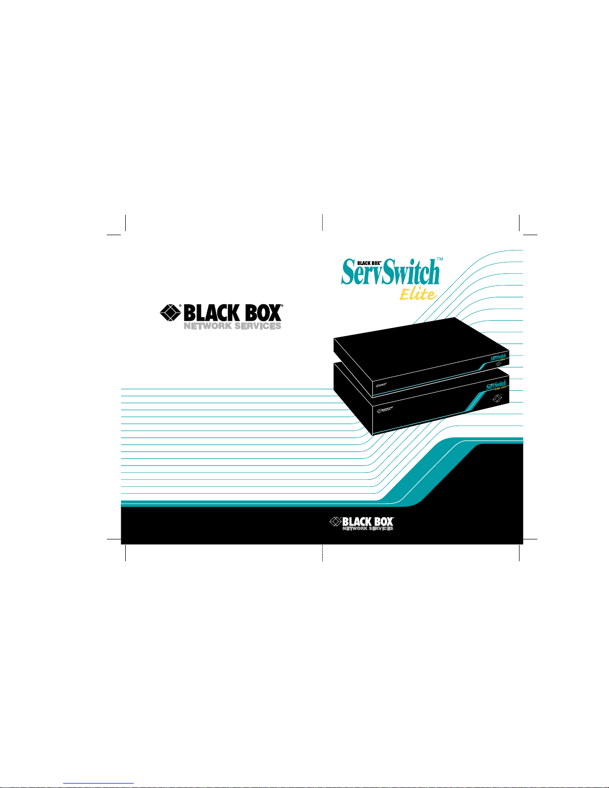
In systems involving only one ServSwitch Elite, the keyboard, monitor, and mouse
cables of each user console are connected directly to the Switch by their respective
cables, as shown in Figure 2-1 (for the single-user model) and Figure 2-2 (for the
4x8 model) on the next page. The Switch then connects to the computers (as
many as eight of them) through multiple sets of keyboard-, mouse-, and videoextension cables.
Page 15
14
SERVSWITCH ELITE™
Figure 2-1. A system with one single-user Switch.
Figure 2-2. A single-4x8-Switch system.
Monitor
Monitor
Console 1 . . . . . . . . . . . . . . . . . . . . . Console 4
Keyboard
Keyboard
Mouse
Mouse
Keyboard-, Mouse-,
and Video-
Extension Cables
CPUs
4x8 SERVSWITCH ELITE (KV7148FA)
Monitor
SINGLE-USER SERVSWITCH ELITE (KV7118SA)
Keyboard
Mouse
CPUs
Keyboard-,
Mouse-, and
Video-
Extension
Cables
Page 16

15
CHAPTER 2: Introductiom
2.3.2 M
ULTIPLE
S
ERVSWITCHELITESYSTEMS
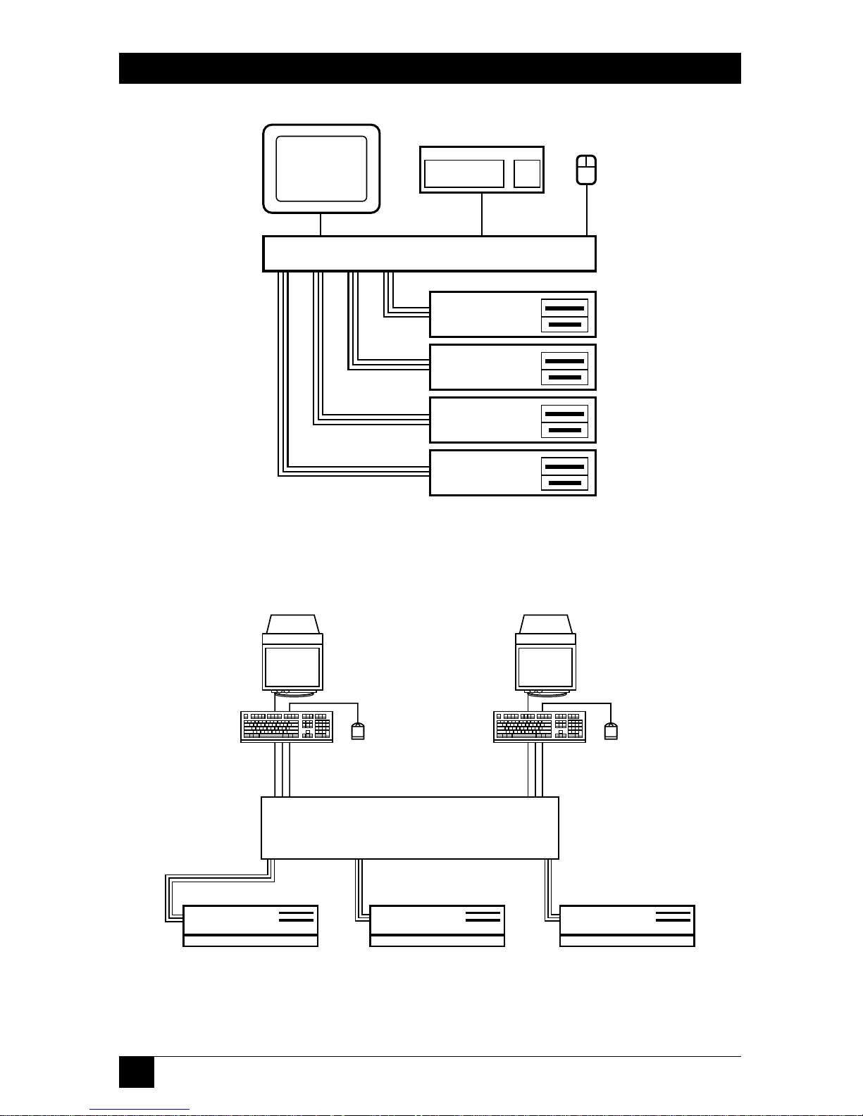
For systems with a large number of computers, ServSwitch Elites can be cascaded in
a master/slave configuration to connect up to 64 computers. You can cascade
Switches by connecting a “slave” (subsidiary) unit’s console port to one of the
computer ports on the “master” (primary) unit, as shown in Figure 2-3 on the next
page (for the single-user model) or Figure 2-4 on page 16 (for the 4x8 model).
Multiple slave Switches can be cascaded from the master in this manner. For more
information on cascaded systems, see Section 3.4.2.
Figure 2-3. A cascaded “single-user”-Switch system.
Monitor
MASTER SINGLE-USER SERVSWITCH ELITE
SLAVE SINGLE-USER SERVSWITCH ELITE
Keyboard
Mouse
CPUs
CPUs
Keyboard-,
Mouse-, and
Video-
Extension
Cables
Keyboard-,
Mouse-, and
Video-
Extension
Cables
Page 17
16
SERVSWITCH ELITE™
Figure 2-4. A cascaded system with a 4x8 Switch master.
Monitor
Monitor
Console 1 . . . . . . . . . . . . Console 4
Keyboard
Keyboard
Mouse
Mouse
Keyboard-, Mouse-,
and Video-
Extension Cables
CPUs
MASTER 4x8 SWITCH
SLAVE SINGLE-USER SWITCH
Page 18

17
CHAPTER 3: Installatiom
3. Installation
3.1 Unpacking the Switch/The Complete Package
We ship the ServSwitch Elite in packaging designed to protect the system during
shipping and handling. We recommend that you save the carton and packing
materials in case you need to transport the Switch later.
The complete ServSwitch Elite system you should have received includes:
• The ServSwitch Elite main unit.
• Its power cord.
• This manual.
Please contact Black Box right away if anything is missing or arrived damaged.
3.2 Setting DIP Switch F (4x8 Model Only)
In its factory-default “cooperative” state, the ServSwitch Elite 4x8 (KV7148FA)
always resolves port/slave contention in favor of existing connections: Even if a
console is idle, no matter how long it has been in control of a computer port, no
other console can connect either to that port (if the port’s on a single or master
Switch) or to any port on that unit (if the port’s on a cascaded slave Switch). If
another console tries to do so, the attempt is denied and the other console
becomes “deselected” (not connected to any port). For example, suppose the user
at Console A has selected computer port 3 and the user at Console B has selected
port 6. If Console A’s user tries to select port 6, the request will be ignored and
Console A will lose its connection to port 3, becoming disonnected from all of the
computer ports until its user selects another.
If this is OK with you, go on to Section 3.3. But if you would like your 4x8 Switch
to always resolve port/slave contention in favor of new connections instead—so
that, in the above example, Console A would get port 6 and Console B would be
displaced (not connected to any computer port, with its monitor blanked)—you
need to move its DIP switch F to the “preemptive” setting. Following the first part
of the procedure for upgrading the Switch’s firmware (see Appendix B), open the
little panel on the bottom of the unit, exposing an area of the circuit board that
contains a block of four DIP switches. Move the switch marked “1-1” on the left end
of the block to the “ON” position and close the panel back up again. Your Switch is
now set to “preemptive” mode, and will allow any console to select any computer
port at any time, even if doing so disrupts previously established console-tocomputer-port connections.
Page 19

18
SERVSWITCH ELITE™
3.3 Rackmounting Switches (Optional)
Rackmount kits are available if you want to mount either model of the ServSwitch
Elite in an EIA-standard 19" equipment rack. (This is especially useful if you want
to attach the Switch to computers that are already mounted in the same or
adjoining racks.) Figure 3-1 on the next page shows how to attach the mounting
brackets from the RMK19E kit to the single-user Switch; Figure 3-2 on the next
page shows how to attach the brackets from the RMK19E4 kit to the 4x8 Switch.
Follow safety measures when you install this equipment:
• Before you mount a Switch, make sure it is turned off and unplugged.
• Before you mount a Switch or other components in a rack cabinet, stabilize
the cabinet in a permanent location. Start rackmounting your equipment at
the bottom of the cabinet, then work your way to the top. Avoid uneven
loading or overloading of cabinets.
CAUTION!
Do not exceed your cabinets’ load rates. Overloading or uneven loading
of a cabinet might result in shelf or cabinet failure, causing equipment
damage and possibly personal injury.
When you do connect the ServSwitch Elite to a power source,
connect it only to the type of power supply specified on the unit’s
housing. Do not exceed the current or voltage capacity of the Switch or
of your site’s circuits. Overloaded power sources, extension cords, etc.,
pose fire and shock hazards.
Take these steps to rackmount your Switch:
1. Line up the holes in the “long side” of the Kit’s side brackets with the
screwholes in the sides of the ServSwitch Elite.
2. With an Allen wrench, fasten the mounting brackets to the Switch using two of
the included 8-32 x
3
⁄
8" button-head socket-cap screws per side.
3. Attach the included rack nut/holders to the mounting rail of the rack so that
they are positioned on the inside of the cabinet.
4. Mount the Switch assembly to the cabinet by matching the holes or grooves on
the “short side” of each bracket to an appropriate set of matching holes on
your equipment rack, then inserting the included 10-32 x
1
⁄2" Phillips truss-head
screws through the holes or grooves in the bracket and the holes in the
mounting rail, into the rack nut/holders, then tightening the screws to secure
the assembly in place.
Page 20

19
CHAPTER 3: Installatiom
Figure 3-1. Rackmounting the single-user Switch with the RMK19E kit.
Figure 3-2. Rackmounting the 4x8 Switch with the RMK19E4 kit.
Page 21

20
SERVSWITCH ELITE™
3.4 The Installation Procedure
Use the procedures described in the following subsections to install your
ServSwitch Elite system. Refer to Figure 3-6 (for the single-user model) and
Figure 3-7 (for the 4x8 model) on page 24 for general guidelines about where
Switch components are and what they’re for.
3.4.1 P
LACING THEUNPOWEREDSWITCHES
Before you do anything else, take these steps:
1. Make sure that each ServSwitch Elite you plan to install is turned off and
unplugged.
2. Place any Switches that you haven’t already rackmounted (see Section 3.3) in
your desired location(s).
3.4.2 C
ASCADINGSWITCHES(OPTIONAL
)
A cascaded ServSwitch Elite system configuration allows the greatest flexibility and
capacity. A cascaded configuration can include up to nine Switches and as many as
64 computers: In a cascaded system, the Switch connected to the main console(s)
becomes the master or primary Switch; a layer of slave or secondary Switches are
connected to the master Switch’s computer ports. One master can accommodate
eight slaves; thus, on a system with eight computers connected to each of the eight
slaves, the users on the master Switch’s console(s) can access 64 computers.
One thing you have to remember in a cascaded system is how the ports are
numbered. The ServSwitch Elite system treats slaves’ computer ports much like
ports on a master or single Switch, but in the Switch’s on-screen menus, the
numbers of ports on a slave Switch are designated as “digit1-dash-digit2,” where
“digit1” is the slave’s port on the master and “digit2” is the computer port on the
slave. For example, a computer connected to Port 2 on a slave Switch which is
connected to Port 1 on a master Switch would be numbered “1-2.”
When you’re finished installing your system, you might find it helpful to assign a
name to each slave Switch (see Sections 4.2.7 and 4.2.10).
Page 22

21
CHAPTER 3: Installatiom
To connect a cascaded ServSwitch Elite system, take these steps, referring to
Figures 3-4 and 3-5 on the next page:
1. Plug keyboard-, mouse-, and video-extension cables into a set of console
connectors on the rear panel of the slave Switch. If your slave is a single-user
unit, the keyboard, mouse, and monitor connectors will be the only console
connectors you have to choose from. If your slave is a 4x8 unit, we
recommend that you use the “Console A” connectors.
NOTE
You can have “local” consoles connected to the other console
connectors on a slave 4x8 Switch. These consoles will contend with the
master’s console(s) for access to the CPU ports on that slave, but they
will not be able to access CPU ports on the master or on any other
slaves.
2. Plug the other ends of your keyboard- and mouse-extension cables into the
6-pin mini-DIN sockets marked “K” and “M,” respectively, below one of the
numbered port labels on the rear panel of the master Switch. Plug the other
end of the video-extension cable into the associated HD15 female VGA
connector. (You might want to bundle and label these cables for easy
identification.)
For your cascade connections, we suggest that you start with CPU port
“One” on the master Switch and use progressively higher-numbered ports as
necessary.
NOTE
Later, once you’ve finished installing your ServSwitch Elite system and
it’s operational, you’ll be able to connect a slave Switch to your master
Switch while the system is running, if necessary. (This can be useful
when you’re trying to isolate problems with minimum disruption to the
system.) Because the master Switch interprets the keyboard connection
as the slave Switch powering up, you must first connect the slave’s
mouse- and video-extension cables, then the keyboard-extension cable.
This completes the physical installation of your cascade. Later, however, after the
fully installed system has been powered up, you must tell the master Switch which
of its CPU ports are hosting slave Switches instead of computers, or the system
won’t work. To do so, follow the directions in Section 4.2.10. Also, you must
configure your ServSwitch Elite system through the master Switch; see the note on
page 30.
Page 23

22
SERVSWITCH ELITE™
Figure 3-4. Cascaded ServSwitch Elite system with a
single-user master Switch.
Figure 3-5. Cascaded ServSwitch Elite system with a 4x8 master Switch.
Master Switch—CPU ports remain
logically numbered 1 through 8
Slave Switch—CPU ports become
logically numbered 1-1 through 1-8
Keyboard-,
Mouse-,
and Video-
Extension
Cables
CPU
Port 1
Console
Port
Master Switch—CPU ports remain
logically numbered 1 through 8
Slave Switch—CPU ports become
logically numbered 1-1 through 1-8
Keyboard-, Mouse-, and
Video-Extension Cables
CPU
Port 1
Console
Port
Page 24

23
CHAPTER 3: Installatiom
3.4.3 C
ONNECTING THE
C
ONSOLEEQUIPMENT
Each ServSwitch Elite console consists of a keyboard, a mouse or trackball, and a
monitor. Note that the keyboard and mouse ports on the rear panel of the Switch
are PS/2 style 6-pin mini-DIN connectors, and each monitor port is a VGA/SVGA
style HD15 connector. This means that to attach a standard console, all you need
to do is plug the monitor, keyboard, and mouse directly into the Switch. On a
single-user Switch, attach them to the monitor, keyboard, and mouse (console)
connectors on the left end of the rear panel (see Figure 3-4 on the previous page);
on a 4x8 Switch, attach them to the monitor, keyboard, and mouse connectors of
“Console A,” “Console B,” “Console C,” or “Console D” on the top half of the rear
panel (see Figure 3-5 on the previous page).
If you need to run farther to your console equipment than its native cables will
reach, you can use our special three-in-one User-Extension Cables (not included,
our product code EHN409) or regular male-to-female keyboard-, mouse-, and
video-extension cables (not included) to connect a standard monitor, keyboard,
and mouse to a console port on the Switch. (The design of the User-Extension
Cable is shown in Figure 3-8 on page 25; it is available in a 10-foot [3-m] and
30-foot [9-m] lengths, but we don’t recommend trying to run console-side
extension cabling farther than 12 ft. [3.6 m] in ServSwitch Elite applications,
because 18 ft. [5.5 m] is all the farther some keyboards and mice can be from the
Switch and still operate.)
If any of your keyboard, mouse, or monitor cables have different connectors,
some adapters and special cables are available from us as stock items and some are
available on a special-quote basis (call Black Box Technical Support); some others
you might have to get from the manufacturer of the peripheral you want to
connect. For more information about keyboard-, mouse-, and video-connector
pinouts, see Appendix D.
NOTES
Later, once you’ve finished installing your ServSwitch Elite system and
it’s operational, you’ll be able to connect a mouse and/or keyboard to
the Switch while the system is on. When you connect a new device, the
Switch will recognize the device and configure it to match the settings
of the currently selected computer. This will allow you to replace failed
devices without having to restart the system.
Whenever you make these kinds of changes to the system, you
should save its hardware-configuration settings. If you do not save the
settings, they will be lost when the Switch loses power or is turned off.
For more information, see Section 4.2.3.
Page 25

24
SERVSWITCH ELITE™
Figure 3-6. Rear panel of the single-user ServSwitch Elite.
Figure 3-7. Rear panel of the ServSwitch Elite 4x8.
To Monitor
To Monitor
From CPU 3’s
Video Port
From CPU 2’s
Video Port
Power
Inlet
Power
Inlet
Power
Switch
Power
Switch
To CPU 3’s
Keyboard Port
To CPU 2’s
Keyboard Port
To CPU 3’s
Mouse Port
To CPU 2’s
Mouse Port
From
Keyboard
From Keyboard
From
Mouse
From Mouse
Auxiliary
Auxiliary
Page 26

25
CHAPTER 3: Installatiom
Figure 3-8. The User-Extension and CPU-Extension Cables.
HD15
Central
video
strand
Keyboard and mouse
strands molded to sides
Cross-section:
9"
(22.9
cm)
10"
(25.4
cm)
6-Pin
mini-DIN
6-Pin
mini-DIN
Page 27

26
SERVSWITCH ELITE™
3.4.4 C
ONNECTING THE
C
OMPUTERS
Computer CPUs can be attached to the ServSwitch Elite through the CPU ports on
its rear panel. Because the keyboard and mouse connectors on both the Switch
and standard PCs are 6-pin mini-DIN female, and the video connectors on both
the Switch and standard PCs are HD15 female, you can use our special three-inone CPU-Extension Cables (not included, our product code EHN408) or regular
male-to-male keyboard-, mouse-, and video-extension cables (not included) to
connect your standard computer CPUs to the Switch. (The design of the CPUExtension Cable is shown in Figure 3-8 on the previous page; it is available in 5-foot
[1.5-m], 10-foot [3-m], 30-foot [10-m], and 50-ft. [15-m] lengths.) Take these steps:
1. Make sure all of the CPUs are turned OFF and unplugged.
2. Run the keyboard- and mouse-extension cables from the CPU’s keyboard and
mouse ports to the keyboard and mouse connectors (marked “K” and “M”
respectively) of one of the Switch’s CPU ports.
3. Run the video-extension cable from the CPU’s video port to the video
connector of the same CPU port on the Switch.
When you’re finished, you might want to bundle and label these cables for easy
identification.
If your computer has different keyboard-, mouse-, or video-port connectors, or if
it uses sync-on-green video, some adapters and special cables are available from us
as stock items and some are available on a special-quote basis (call Black Box
Technical Support); some others you might have to get from the manufacturer of
the computer you want to connect.
For example, if you want to connect a computer with a serial mouse port, you’ll
need to use the mouse adapter included with the KV7150A PC/AT Serial Mouse
Converter Kit (KV7150A) to translate the PS/2 mouse protocol into RS-232 serialmouse signals.
Or, if you want to connect an IBM RS/6000
\
with a 13W3 female video port,
you’ll need our EHN6000-ELITE cable set. It consists of a 12-ft. (3.7-m) videoextension cable with an HD15 male connector on the Switch end and a 13W3 male
connector on the RS/6000 end, plus a pair of standard 6-pin mini-DIN male-tomale PS/2 style extension cables for the keyboard and mouse connections.
Page 28

27
CHAPTER 3: Installatiom
Thirdly, if you want to connect an RS/6000 workstation with a 3C3 female video
port or an HP9000 workstation, both of which use the “composite sync on green”
video format, you’ll need to use the video adapter included with the RS/6000
Converter Kit (KV7160A) or HP9000 Converter Kit (KV7170A) respectively. This
adapter breaks the composite sync signal out onto separate horizontal and vertical
sync lines, as is standard in regular PC video, and also improves the color balance.
You’ll have to attach one of these adapters to the keyboard and video cables
between the Switch and the workstation’s CPU.
For more information about how the Switch handles RS/6000 computers, see
Appendix C. For more information about keyboard-, mouse-, and video-connector
pinouts, see Appendix D.
NOTES
Later, once you’ve finished installing your ServSwitch Elite system and
it’s operational, you’ll be able to connect additional computers to the
Switch while the system is on. When you power up a newly connected
CPU, the Switch will recognize it, and you should be able to select it
right away.
Whenever you make these kinds of changes to the system, you
should save its hardware-configuration settings. If you do not save the
settings, they will be lost when the Switch loses power or is turned off.
For more information, see Section 4.2.3.
3.4.5 C
ONNECTING THEPOWER
To connect your ServSwitch Elite to AC power, first plug the IEC 320 outlet of the
Switch’s power cord into the IEC 320 power inlet on the back of the Switch. Plug
the other end—which should have a plug appropriate for your country or region
on it—into an AC outlet on a UPS (uninterruptible power supply), which we
highly recommend, or directly into a utility (mains) outlet if you don”t have a UPS.
Your Switch system should now be ready for operation. Go on to Section 3.5.
Page 29

28
SERVSWITCH ELITE™
3.5 Initial Power-Up: Turning On the System
The first time you power up your ServSwitch Elite system, do it this way:
1. If you haven’t already done so, attach its power cord to the Switch and plug
the cord into a utility (mains) outlet.
2. Turn on your shared monitor(s).
3. Turn on the ServSwitch Elite by moving the power switch on its rear panel
from the O position to the | position. This switch is on the far right end of the
Switch’s rear panel, as shown in Figures 3-6 and 3-7 on page 24.
4. Power up all of the attached CPUs (if you’re not sure how, see the computers’
manuals).
The Switch has to be turned on before the computers because the computers’
keyboard, mouse, and video drivers send device-configuration requests/commands
out of the corresponding ports. If the Switch is already ON, it can generate
standard responses to these transmissions so that the PCs can boot normally even
though they aren’t physically connected to a keyboard, monitor, or mouse. If the
Switch is OFF, however, the PCs will probably either hang, crash, or boot into an
abnormal state.
NOTE
Later, once your ServSwitch Elite system is fully installed and
operational, the Switch will help your computers recover from power
outages. All of the computers attached to a Switch that are designed to
reboot themselves automatically (without user intervention) will do so
when power returns. The Switch generates responses to ensure that the
reboot is successful and that the Switch is ready to switch between
computers when regular operation resumes.
The Switch also does a few other things while it helps the PCs to boot:
1. It detects the device settings requested by the PC drivers. (You will probably
want to save these settings to the Switch’s NVRAM, so that it loads them
automatically each time it powers up—see Section 4.2.3. You can manually
change these NVRAM device settings later.)
2. It identifies the type of keyboard and mouse that are actually attached to each
of its consoles and puts them in their default states.
3. It displays revision information about its hardware and firmware on the
monitor screen.
Page 30

29
CHAPTER 3: Installatiom
4. The single-user ServSwitch Elite model automatically makes the startup-port
selection: By default, the single-user model will switch its console to
CPU port 1. The consoles’s monitor should display the number of the CPU
port it’s connected to in a “status flag” box that looks something like this:
If the monitor doesn’t display rev-level info or a status flag, check to make
sure that it’s plugged in, turned on, and connected to the Switch.
The 4x8 model will not make any automatic port selections; consoles A, B,
C, and D will be deselected (not connected to any CPU port) at startup.
Page 31

30
SERVSWITCH ELITE™
4. Operation and Configuration
Basic operation of the ServSwitch Elite is performed through the keyboard and a
series of windows and menus that appear on the console display. Through these
menus, you can perform functions such as switching between computers and
checking port/computer status. You can get into these menus by pressing the
[Print Screen] key; once you do, you can communicate directly with the Switch
using your keyboard and monitor.
Table 4-1 on the next page shows how the ServSwitch Elite uses or affects certain
keys on the shared keyboard, especially in regards to the on-screen menu. For
more information on navigating the Switch’s on-screen display, refer to
Appendix A.
NOTE
In ServSwitch Elite systems, a single press of the [Print Screen] key—
which on some computers (in ordinary conditions) causes the computer
to capture or print out the current screen—is used to initiate the
Switch’s on-screen menus and port-switching process instead. To print
a screen displayed by a computer attached to the system, you’ll have to
press [Print Screen] twice if the computer is attached to a single or
master Switch or four times if the computer is attached to a slave
Switch.
In cascaded systems, this [Print Screen] keypress activates the
menus and port-switching functions at the master Switch, which
controls switching, scanning, and configuration for the whole system.
Even though in a cascaded system you can press [Print Screen] a
second time to access these functions on the currently selected slave
unit, we do not recommend doing this except for very limited slavespecific switching, status-checking, or scanning purposes. Do not
change the factory-default configuration values on a slave; setting a
master and slave to conflicting configuration values will cause the
system to behave unpredictably.
See Table 4-2 on the next page for a list of the effects of repeatedly
pressing [Print Screen] in ServSwitch Elite systems.
Page 32

31
CHAPTER 4: Operation and Configuration
Table 4-1. Keyboard Commands/Effects of the ServSwitch Elite’s
On-Screen Display
Key(s) Perform This Action or Are Affected This Way
[Print Screen] If pressed once, opens the single or master Switch’s on-screen display to
the main SERVSWITCH ELITE menu. For effects if pressed more than
once, see Table 3-2 below.
[F1] If pressed at the SERVSWITCH ELITE menu, opens the HELP screen.
[F2]
If pressed at the SERVSWITCH ELITE menu, opens the FUNCTIONS
menu.
Arrows If pressed at a menu, move the highlight bar through available selections.
([↑] [↓] [←] [→]) one at a time.
[PgUp], [PgDn] If pressed at the SERVSWITCH ELITE menu, move the highlight bar
(page up, page down) through available selections eight at a time.
[+] or [–] If pressed while a value is highlighted, changes that value.
[Enter] If pressed while at a menu, saves current or changed settings, returns to
next-higher-level menu.
[Esc] (escape) If pressed while typing in a new value, or at a subsidiary menu, aborts any
changes in progress and returns to next-higher-level menu. If pressed at
a high-level menu, exits the on-screen display.
Numeric keypad Always in the numeric state, even if the Num Lock LED on the keyboard
indicates otherwise.
[Caps Lock] Disabled—use the [Shift] key to change case.
Table 4-2. Effects of the [Print Screen] Key
In this kind of system... ...here’s what [Print Screen] does if you press it:
Single ServSwitch Elite Once: Opens on-screen display.
Twice: Clears the screen, then (if this function is enabled on the
currently selected computer) captures or prints the screen.
Cascaded ServSwitch Elites Once: Opens on-screen display on master Switch.
Twice: Opens on-screen display on currently selected slave.
Three times: Opens on-screen display on both master and slave.
Four times: Clears the screen, then (if this function is enabled on
the currently selected computer) captures or prints the screen.
Page 33

32
SERVSWITCH ELITE™
4.1 Basic Operation
You can do basic things with the ServSwitch Elite, like switching between its
computer ports or checking computer/port status, from the main window of the
Switch’s on-screen display. Pressing [Print Screen] brings this SERVSWITCH
ELITE window up on screen; it lists all of the ports in the system, any associated
computer names, and the status of each port. It can be organized by either port
number or by name (see Section 4.2.8); You can scroll through the list with the up-
and down-arrow ([↑] and [↓]) keys and, on large systems, the [Page Up] and
[Page Down] keys. From this window, you can press [F2] to reach the FUNCTIONS
menu or [F1] to see a very basic help screen. You can press [Esc] (escape) to exit
the on-screen display, make the window disappear, and return to normal
operation.
Figure 4-1 on page 34 shows you what this window would look like in a sample
ServSwitch Elite 4x8 system. The actual appearance of this window in your system
will depend on how you configure the window and how you name your computers.
In its factory-default state, this window is ordered by port number and the
computers are named “COMPUTER1,” “COMPUTER2,” and so on.
4.1.1 S
WITCHINGBETWEEN
C
OMPUTERS
Switching computer ports electrically disconnects your console’s keyboard, mouse,
and monitor from the currently connected computer and connects them to the
newly selected computer. In the ServSwitch Elite 4x8’s factory-default “cooperative”
state, if another console is already connected to the selected computer, or to any
computer on the same slave Switch as your selected computer, you will not be
connected to that computer; you will also become disconnected from your
previously selected computer. (If you want new connections to displace existing
connections instead, you can set the 4x8 model’s internal DIP switch F to
“preemptive”—see Section 3.2.) If you want to determine if a listed computer is up
and running, or if some other console is already connected to any computer in the
system, refer to Section 4.1.2.
You can switch from one computer port to another by typing commands at your
keyboard:
1. Press and release the [Print Screen] key. The SERVSWITCH ELITE window
will appear on screen in one of the two formats shown in the sample in
Figure 4-1 on page 34. (Whether the computers are listed by port number or
name is determined by the current setting of that particular menu attribute;
see Section 4.2.8.)
Page 34

33
CHAPTER 4: Operation and Configuration
2. Move the highlight bar to the computer you want to switch to in one of three
ways:
• Use the up-arrow and down-arrow keys ([↑] and [↓]).
• If the computers/slaves are listed in the SERVSWITCH ELITE window by their
port numbers: Press the number key(s) corresponding to the computer’s port
number. To enter port numbers for slave ports in cascaded systems (see
Section 3.3.2), press the number key for the slave’s master port, then the
minus/dash ([–]) key, then the number key for the computer’s slave port; if
there isn’t actually a slave unit on the master port you type in, the command
will be immediately aborted.
• If you have assigned a name to the computer or slave, and the computers/slaves are
listed in the SERVSWITCH ELITE window by their assigned names (they will be
shown in alphabetical order): Type in the computer’s/slave’s name (or the first
portion of its name) on the keyboard.
3. Press [Enter] to make your selection.
For example, to select the computer connected to Port 2 when the menu is
ordered by port number, you would press and release [Print Screen], then [2],
then [Enter].
Each time you switch computer ports, the Switch first reconfigures your
keyboard and mouse to the operating state it has stored in its memory for the
selected computer. For example, if that computer has [Caps Lock] on, the Switch
will put the keyboard in [Caps Lock] mode. Only after it finishes making these
configuration adjustments will the Switch pass the computer’s video output
through to your monitor.
When you are finished switching, the SERVSWITCH ELITE window
automatically disappears from the display. As long as the status flag is enabled (see
Section 4.2.9), the flag returns to the display to indicate the currently connected
computer.
Page 35

34
SERVSWITCH ELITE™
Figure 4-1. The main SERVSWITCH ELITE menu for a hypothetical
ServSwitch Elite 4x8 system with seven computers, order ed by
port number (left) and name (right).
SERVSWITCH ELITE
NAME PORT
CENTRALOFC 2 + B
DOWNTOWN 6
FOREIGN 7 +
MAGIC 1 +
SALES-A 5 +
SALES-B 4
SALES-C 3 + D
8
F1 HELP F2 FUNCTIONS
SERVSWITCH ELITE
PORT NAME
1 MAGIC +
2 CENTRALOFC + B
3 SALES-C + D
4 SALES-B
5 SALES-A +
6 DOWNTOWN +
7 FOREIGN +
8
F1 HELP F2 FUNCTIONS
Page 36

35
CHAPTER 4: Operation and Configuration
4.1.2 C
HECKING
P
ORT/COMPUTERSTATUS
The SERVSWITCH ELITE window shows port/computer status, so you can
determine:
• Which ports are currently active and whether they have a computer or a slave
ServSwitch Elite connected, and
• Which ports are currently selected by different consoles in the system.
To check port/computer status:
1. Press [Print Screen]. The SERVSWITCH ELITE window appears on the
display as shown in Figure 4-1 on the previous page. It lists the names,
numbers, and statuses of all of the CPU ports in the system. The order in
which the computers are listed, by port number or by name, is determined as
described in Section 4.2.8.
The status is indicated by the characters in the two right-hand columns.
The third column will contain one of these characters:
• Null (blank): Either the device attached to this port is turned off or
unplugged, or there simply isn’t any device attached.
• Plus (“+”): There is a powered computer attached to this port.
• The letter “X”: There is a powered slave Switch attached to this port.
Only the 4x8 units will have a fourth column in this window; if there is a
character in this column, it will identify the console that has selected the
computer (“A” for console A, “B” for console B, etc.).
2. Press [Esc] (escape) to exit the on-screen display and make it disappear.
Page 37

36
SERVSWITCH ELITE™
4.2 Higher-Level Operation and Configuration: The FUNCTIONS Menu
The ServSwitch Elite can perform other functions that involve displaying system
information, configuring the system, and troubleshooting the system. These
functions, accessible through the on-screen FUNCTIONS menu, include:
Operating functions (the COMMANDS submenu):
• Scanning the computers in the system (see Section 4.2.1).
• Displaying ServSwitch Elite firmware version and settings (see Section 4.2.2).
• Saving system settings (see Section 4.2.3).
• Resetting the selected CPU’s mouse and keyboard ports (see Section 4.2.4).
• Single-user (KV7118SA) model only: Broadcasting to multiple computers in the
system (see Section 4.2.5).
Configuration functions (the SETUP submenu):
• Setting up a special scan pattern (see Section 4.2.6).
• Assigning unique names to the computers in the system (see Section 4.2.7).
• Listing computers by name or port number in the on-screen windows (see
Section 4.2.8).
• Changing the position and color of the operation menus and windows (see
Section 4.2.8).
• Changing the attributes of the status flag (see Section 4.2.9).
• Assigning a specific monitor type to a certain port (computer) (see
Section 4.2.10).
• Setting security options for each Switch (see Section 4.2.11).
For information on how to make entries and selections in the menus, refer to
Appendix A.
Page 38

37
CHAPTER 4: Operation and Configuration
4.2.1 S
CANNING THE
C
OMPUTERS IN THESYSTEM
When you place it in “scan mode,” the ServSwitch Elite automatically switches the
video connection sequentially from port to port (computer to computer), so you
can observe the state of any or all of the computers in the system.
Instead of sequential uniform scanning, you can set up a scan mode that
includes specific computers in, or excludes them from, the scan. For this custom
scan mode, you can specify that the computers be scanned in a given sequence,
and for variable durations. Refer to Section 4.2.6.
To place the Switch in the scan mode, take these steps:
1. Press [Print Screen]. The SERVSWITCH ELITE window appears.
2. Press [F2] and the FUNCTIONS window appears. The Commands menu will be
displayed and its first entry (SCAN) will be highlighted.
3. Press [Enter]. At this point, the Switch enters scan mode and the display
returns to the status flag. You can press [Esc] (escape) at any time prior to
pressing [Enter] to cancel the operation.
To get out of scan mode, press any key on the keyboard or move the mouse. The
scan stops at the currently connected computer.
On the ServSwitch Elite 4x8 (KV7148FA), each of the four consoles can scan the
system independently. You can scan computer ports controlled by other consoles if
those ports are on a master or single Switch; however, if you try to scan any port on
the same slave Switch as a port controlled by another console, or if you try to stop
the scan at a port controlled by another console, the Switch will react in one of two
ways depending on the setting of DIP switch F (see Section 3.2):
• In the factory-default “cooperative” setting, the Switch will not let you stop
your scan on any computer port controlled by another console. You will
instead be “deselected”—not connected to any port, with video blanked—until
you select a different port. If you try to scan any port on the same slave Switch
as a port controlled by another console, you will not see anything (the video
will be blank).
• In the “preemptive” setting, if you stop your scan on a port controlled by
another console—or even if you scan any port on the same slave Switch as a
port controlled by another console—the Switch will connect you to that port
and will deselect the console that was in control of that port, or the other port
on that slave—instead.
Page 39

38
SERVSWITCH ELITE™
4.2.2 D
ISPLAYING
V
ERSIONINFORMATION ANDDEVICESETTINGS
To make troubleshooting and supporting the system easier, the ServSwitch Elite's
firmware-version number can be displayed along with specific keyboard and mouse
information for the currently selected computer. To display this information, take
these steps:
1. Press [Print Screen]. The SERVSWITCH ELITE window appears.
2. Press [F2] and the FUNCTIONS window appears. The Commands menu will be
displayed.
3. Using the up and down arrow ([↑] and [↓]) keys, move the highlight bar to
VERSION and press [Enter]; the VERSION window will appear:
Figure 4-2. The VERSION window.
In this window, the keyboard information includes enabled/disabled,
typematic rate, LED settings, scan mode, and keyboard type. The mouse
information includes enabled/disabled, sample rate, resolution, and mouse
type. Note that the entry for DIP SWITCH F will appear on both single-user
and 4x8 units, but only 4x8 units will show a value for the switch’s setting
(COOPERATIVE or PREEMPTIVE) because the setting is irrelevant on singleuser units.
4. Press [Esc] (escape) to exit the Version window.
VERSION
FIRMWARE X.X.X BB
HARDWARE X.X 8PORT
DIP SWITCH F COOPERATIVE
PORT 1 MAGIC
KEYBOARD MOUSE
ENABLED ENABLED
RATE 2C RATE 100
LEDS 2 RES 2
MODE 2
TYPE 101 TYPE GEN
Page 40

39
CHAPTER 4: Operation and Configuration
4.2.3 S
AVING THE
H
ARDWARECONFIGURATION
Whenever computers are added to or removed from the system, or whenever there
is a change in any keyboard or mouse, the hardware-configuration settings should
be saved to the ServSwitch Elite’s nonvolatile memory. If the settings are not saved,
they will be lost whenever Switch power is lost or turned off.
CAUTION!
If settings are not saved and Switch power is lost, it might be necessary
to reboot each computer in the system to reestablish keyboard and
mouse communication.
To save the Switch’s configuration settings to NVRAM, take these steps:
1. Press [Print Screen]. The SERVSWITCH ELITE window appears on the
display.
2. Press [F2] and the FUNCTIONS window appears. The Commands menu will
be displayed.
3. Using the up- and down-arrow ([↑] and [↓]) keys, move the highlight bar to
SNAPSHOT.
4. Press [Enter]. The hardware settings are now saved to memory.
4.2.4 R
ESETTING THEMOUSE ANDKEYBOARDPORTS
If you want to try to restore the correct keyboard and mouse settings for the
selected computer, you can reset the CPU’s mouse and keyboard ports by taking
these steps:
1. Press [Print Screen]. The SERVSWITCH ELITE window appears on the
display.
2. Press [F2] and the FUNCTIONS window appears. The Commands menu will
be displayed.
3. Using the up- and down-arrow ([↑] and [↓]) keys, move the highlight bar to
RESET.
4. Press [Enter]. The default settings of the mouse and keyboard ports have now
been restored.
Page 41

40
SERVSWITCH ELITE™
4.2.5 U
SING
B
ROADCASTMODE(SINGLE-USERMODELONLY
)
With the single-user (KV7118SA) ServSwitch Elite’s “broadcasting” feature, you can
simultaneously control more than one computer in a system. (At least the Switch
attempts to send keystrokes and mouse commands to the selected computers
simultaneously; however, some computers might inhibit and thus delay the
transmission.) This feature is useful when you want to make sure that all selected
computers receive identical input. For each computer receiving the broadcast, you
can choose to broadcast keystrokes, mouse movements, or both.
NOTES
For all computers receiving a broadcast to interpret commands
identically, the keyboard and mouse states for the computers must be
identical. Specifically, the [Caps Lock] and [Num Lock] modes should be
the same on all keyboards. For the mouse to work accurately, all
systems must have identical mouse drivers, identical desktops, and
identical video resolutions. In addition, the mouse must be in exactly the
same place on all screens. Because these conditions are extremely
difficult to achieve, broadcasting mouse movement to multiple systems
might have unpredictable results.
While broadcast mode is on, the status flag will indicate it with a “broadcast
symbol” to the right of the port number or name:
You will use either of two procedures to select a group of ports and broadcast to it,
depending on whether you want to include any slave ports. If you want to
broadcast to ports on a single or master Switch only, take these steps:
1. Press [Print Screen]. The SERVSWITCH ELITE window appears.
2. Press [F2] and the FUNCTIONS window appears. The Commands menu will
be displayed. Press the right arrow ([→]) key to move the highlight bar so
that the Setup menu is displayed.
3. Using the down-arrow ([↓]) key, move the highlight bar to BROADCAST in
the Setup menu.
Page 42

41
CHAPTER 4: Operation and Configuration
4. Press [Enter]. The BROADCAST SETTINGS window appears:
Figure 4-3. The BROADCAST SETTINGS window.
5. For each port listed, select whether or not you want the computer to receive
broadcast keyboard or mouse data. Use the up- and down-arrow ([↑] and
[↓]) keys to move up and down the port list, the right- and left-arrow ([←]
and [→]) keys to move back and forth between the columns, and the [+] or
[–] key to toggle between “YES” and “NO.”
6. Prcss [Enter] to save the settings. You will be returned to the FUNCTIONS
window.
7. Press the left-arrow ([←]) key to move the highlight bar so that the
Commands menu is displayed. Using the down-arrow ([↓]) key, move the
highlight bar to BROADCAST in the Commands menu.
8. Press [Enter] to activate broadcast mode. The on-screen display will
disappear. Type in the keyboard data and/or make the mouse movements
you want to broadcast. When you’re finished, press [Print Screen], then [F2],
then scroll down to BROADCAST in the Commands menu and press [Enter]
to turn broadcast mode off.
If you want to broadcast to a set of ports that includes slave ports, you have to set up
individual broadcast groups on each Switch. Take these steps:
1. Follow steps 1 through 6 of the “single or master Switch only” procedure to
select all of the ports on the master Switch that are occupied by computers
you want to broadcast to.
2. Press [Print Screen]. The master Switch’s SERVSWITCH ELITE window
appears.
BROADCAST SETTINGS
PORT KEYBOARD MOUSE
1 YES YES
2 NO NO
3 YES NO
4 YES YES
5 NO NO
6 NO YES
7 YES YES
8 YES YES
Page 43

42
SERVSWITCH ELITE™
3. Using the up- and down-arrow ([↑] and [↓]) keys, move the highlight bar to
the number of the master port (shown here as “1-1,” “2-1,” and so on) that
hosts a slave with a port you want to broadcast to.
4. Press [Enter] to select that slave. The master Switch’s SERVSWITCH ELITE
window disappears.
5. Press [Print Screen] twice. The slave Switch’s SERVSWITCH ELITE window
appears.
6. Press [F2] and the FUNCTIONS window appears. The Commands menu will
be displayed. Press the right arrow ([→]) key to move the highlight bar so
that the Setup menu is displayed.
7. Using the down-arrow ([↓]) key, move the highlight bar to BROADCAST in
the slave Switch’s Setup menu.
8. Press [Enter]. The BROADCAST SETTINGS window appears, like the one
shown in Figure 4-3 on the previous page.
9. For each port listed, select whether or not you want the computer to receive
broadcast keyboard or mouse data. Use the up- and down-arrow ([↑] and
[↓]) keys to move up and down the port list, the right- and left-arrow ([←]
and [→]) keys to move back and forth between the columns, and the [+] or
[–] key to toggle between “YES” and “NO.”
10. Press [Enter] to save the settings.
11. Repeat steps 2 through 10 for every other slave Switch with a port you want in
the broadcast group.
12. Press [Print Screen]. The master Switch’s SERVSWITCH ELITE window
appears again.
13. Press [F2] and the FUNCTIONS window appears. Using the down-arrow ([↓])
key, move the highlight bar to BROADCAST in the master Switch’s Commands
menu.
14. Press [Enter] to activate broadcast mode. The on-screen display will
disappear. Type in the keyboard data and/or make the mouse movements
you want to broadcast. When you’re finished, press [Print Screen], then [F2],
then scroll down to BROADCAST in the master Switch’s Commands menu and
press [Enter] to turn broadcast mode off.
Page 44

43
CHAPTER 4: Operation and Configuration
4.2.6 S
ETTING A
S
CANPATTERN
While the ServSwitch Elite is equipped with a standard scan routine for
sequentially connecting each computer to the monitor, keyboard, and mouse
(refer to Section 4.2.1), you can configure a “custom scan” of any or all of the
computers that follows a particular pattern or sequence. To create a custom scan
pattern (which, on a 4x8 Switch, you can do independently for each console), take
these steps:
1. Press [Print Screen]. The SERVSWITCH ELITE window appears on the
display.
2. Press [F2] and the FUNCTIONS window appears. The Commands menu will
be displayed. Press the right arrow ([→]) key to move the highlight bar so
that the Setup menu is displayed and its first entry (SCAN) is highlighted.
3. Press [Enter]. The SCAN PATTERN SETUP window appears with the first
port position (or computer name) highlighted. In the sample window shown
in Figure 4-4 below, the Switch’s ports are ordered by port number; if you
have the ports ordered by name instead (see Section 4.2.8), the PORT and
NAME columns will be reversed in position.
Figure 4-4. The SCAN PATTERN SETUP window.
4. Using the keyboard keys, type in the port number, or the first few letters of
the name, of the first computer to be included in the scan. (See Section 4.2.7
for more information about assigning names to computer ports.) This
computer/port will appear on this line.
SCAN PATTERN SETUP
PORT SEC NAME
6 20 DOWNTOWN
5 20 SALES-A
4 10 SALES-B
1 10 MAGIC
F2 FOR DEFAULTS
Page 45

44
SERVSWITCH ELITE™
5. Press the [Tab] or right-arrow ([→]) key to move the highlight bar to the
SEC column and use the keyboard keys to enter a time value in seconds (up
to 255) that you want this computer to be connected to the console (viewable
on the monitor) before the Switch switches to the next computer in the scan.
To delete a single port from the list, enter “0” (zero) seconds here. To
delete a whole set of unwanted ports at the end of the scan list, which is where
most of them end up after you’ve brought together your list of desired ports
anyway, place the highlight bar on the topmost port to be removed and press
the [Delete] key (not the [Del] key on the numeric keypad). The highlighted
port and all ports below it will be removed from the list.
6. Press the down-arrow ([↓]) key to move the highlight bar to the next line.
7. Repeat steps 5 through 7 as necessary for your remaining computers.
8. When you’ve finished setting the scan pattern, press [Enter]. The new scan
pattern supersedes the standard scan or any previous custom scan. You can
press [Esc] (escape) at any time prior to pressing [Enter] to retain the
previous scan pattern. Pressing the [F2] key will return all PORT and SEC
values to their factory defaults.
To exit the on-screen menus in order to test your new scan pattern, press [Esc].
Page 46

45
CHAPTER 4: Operation and Configuration
4.2.7 A
SSIGNING
U
NIQUENAMES TO THECOMPUTERS ANDSLAVES IN THESYSTEM
It might be helpful to assign unique names to each computer and slave in your
ServSwitch Elite system as a means of easy identification. For example, in a network
environment, the names can be the same as those assigned in the network for each
computer. Assign names as follows:
1. Press [Print Screen]. The SERVSWITCH ELITE window appears on the
display.
2. Press [F2] and the FUNCTIONS window appears. The Commands menu will
be displayed. Press the right arrow ([→]) key to move the highlight bar so
that the Setup menu is displayed.
3. Using the up- and down-arrow ([↑] and [↓]) keys, move the highlight bar to
NAMES.
4. Press [Enter]. The PORT NAMING window appears:
Figure 4-5. The PORT NAMING window .
PORT NAMING
PORT NAME
1 MAGIC
2 CENTRALOFC
3 SALES-C
4 SALES-B
5 SALES-A
6 DOWNTOWN
7 FOREIGN
8
Page 47

46
SERVSWITCH ELITE™
5. Using the up- and down-arrow ([↑] and [↓]) keys, move the highlight bar to
the PORT entry that you want to give a name or change the name of. Type in a
name up to 12 alphanumeric characters long; valid characters are the
uppercase letters “A” through “Z”—you can type lowercase letters, but they’ll
automatically be converted to uppercase—the digits “0” through “9,” and the
“–” (dash, hyphen, minus) character. Press [Backspace] to delete an incorrect
entry or an entry for a device that has been removed from the system. Repeat
this step as necessary.
NOTE
Before you can name computers attached to a slave Switch, you have to
tell the master Switch that the slave is, in fact, a slave; see
Section 4.2.10.
6. Press [Enter] to save the computer name(s) in NVRAM. You can press [Esc]
(escape) at any time prior to pressing [Enter] to cancel the operation.
Page 48

47
CHAPTER 4: Operation and Configuration
4.2.8 C
HANGING THE
M
ENUATTRIBUTES
The menus and windows displayed on the monitor can be altered in visual
appearance to suit the particular use of the system (and on a 4x8 Switch, you can
do so independently for each console). Certain adjustments can be made to the
menus so that:
• The menu is positioned in a convenient location on the display.
• The computers are listed by port or by name, whichever is desired, in the
appropriate menus.
• The character height is suitable for display.
• The colors are suitable.
• The SERVSWITCH ELITE window appears on the display for a certain
period of time.
To change attributes of the on-screen menus, take these steps:
NOTE
It is possible, when you change the menu attributes, to distort the
appearance of the menus/windows so that they are hard or impossible
to read, which obviously makes it difficult to correct the problem. If this
occurs, you can reset the ServSwitch Elite to its factory-default values
for all options accessible through the on-screen display by pressing and
releasing [Esc] (escape) twice, then [Print Screen], then [F10], then the
letter [Y], then [Enter].
1. Press [Print Screen]. The SERVSWITCH ELITE window appears on the
display.
2. Press [F2] and the FUNCTIONS window appears. The Commands menu will
be displayed. Press the right arrow ([→]) key to move the highlight bar so
that the Setup menu is displayed.
3. Using the up- and down-arrow ([↑] and [↓]) keys, move the highlight bar to
ATTRIBUTES.
Page 49

48
SERVSWITCH ELITE™
4. Press [Enter]. The PHYSICAL ATTRIBUTES window appears:
Figure 4-6. The PHYSICAL ATTRIBUTES window.
5. Highlight any setting you want to change and use the [+] and [–] keys to cycle
to the desired value. As you select different values, the effect of the changes is
reflected immediately on the display. Repeat this step as necessary.
The attributes whose values you can change include:
Attribute Effect on Menu/Window Appearance
Resolution Affects the size of the menus and windows as they appear on
the display. Choose from values of 320, 480, and 640; the lower
the value, the larger the size. The factory-default value is 640.
Height Affects the size of the text in the menus and windows. The
larger the value, the larger the text. Possible settings are 1
(1 pixel) to 63 (63 pixels). The factory-default value is 16.
Horizontal Affects the left-to-right positioning of the menus and windows
on the display. Possible settings are 1 (1 pixel from the far left)
to 127 (127 pixels from the far left, which is as far right as it will
go). The factory-default value is 5.
Vertical Affects the top-to-bottom positioning of the menus and
windows on the display. Possible settings are 1 (1 pixel from
the top) to 255 (255 pixels from the top, which is as far down
as it will go). The factory-default value is 11.
PHYSICAL ATTRIBUTES
RESOLUTION 640
HEIGHT 16
HORIZONTAL 12
VERTICAL 7
BACKGROUND 1
HIGHLIGHT 4
TEXT 7
DELAY TIME 0
ORDER PORT
Page 50

49
CHAPTER 4: Operation and Configuration
Background Determines the background color of the menus and windows.
Possible choices are 0 (black), 1 (blue), 2 (light green), 3
(cyan), 4 (red), 5 (magenta), 6 (yellow), and 7 (white). The
factory-default value is 1 (blue).
Highlight Determines the color of the highlight bar appearing in the
menus and windows. Possible choices are 0 through 7 as listed
above. The factory-default value is 4 (red).
Text Determines the color of the text appearing in the menus and
windows. Possible choices are 0 through 7 as listed above. The
factory-default value is 6 (yellow).
Delay Time The time in seconds that elapses after you press [Print Screen]
before the SERVSWITCH ELITE window appears on screen.
The factory-default value is 0 (zero, no delay). You can increase
this delay if you find the window becoming a distraction when
you perform simple computer-switching operations at the
keyboard.
Order Determines the order in which the computers are listed in the
menus and windows: numerically by port number (the factorydefault value), or alphabetically by assigned name.
NOTE
Before you take a formerly autonomous single
Switch and attach it as a slave to a master Switch, it
is very important that you set Order to “PORT” on
that slave Switch; the system could malfunction if
you don’t. In general, we recommend that you reset
any formerly autonomous Switch to its factory
defaults (see the note on page 47) before installing it
as a slave.
6. When you’ve completed all your desired adjustments, press [Enter] to save
the changes to NVRAM. You can press [Esc] (escape) at any time prior to
pressing [Enter] to cancel the operation and retain the previous settings.
Page 51

50
SERVSWITCH ELITE™
4.2.9 C
HANGING THE
A
TTRIBUTES OF THESTATUSFLAG
The small on-screen box called the “status flag” indicates the currently connected
computer and can be set to appear on the screen whenever the system is operating.
You can alter how and where the flag appears on the screen (on a 4x8 Switch, you
can do so independently for each console) by changing one or more of the
following attributes:
• Its appearance on the screen (none, timed, or constant);
• Its position on the screen; or
• Its color and opaqueness.
To change the flag’s attributes, take these steps:
1. Press [Print Screen]. The SERVSWITCH ELITE window appears on the
display.
2. Press [F2] and the FUNCTIONS window appears. The Commands menu will
be displayed. Press the right arrow ([→]) key to move the highlight bar so
that the Setup menu is displayed.
3. Using the up- and down-arrow ([↑] and [↓]) keys, move the highlight bar to
FLAG.
4. Press [Enter]. The FLAG CONFIGURATION window appears:
Figure 4-7. The FLAG CONFIGURATION window.
FLAG CONFIGURATION
ENABLED NAMES ON
ROW 14
COLUMN 1
COLOR 2
TEXT 0
MODE TRANSPARENT
Page 52

51
CHAPTER 4: Operation and Configuration
5. Highlight the setting(s) you want to change and use the [+] and [–] keys to
cycle to the desired value. Repeat this step as necessary.
The flag attributes whose values you can change include:
Attribute Effect on Status-Flag Appearance
Enabled FLAG OFF = Flag does not appear
PORTS ON = Flag indicates the number of the connected port
(the factory-default value)
NAMES ON = Flag indicates the connected device by name
PORTS TIMED = Port number is displayed for 5 seconds after
connection
NAMES TIMED = Name is displayed for 5 seconds after
connection
Row Determines the flag’s vertical position on the screen. This will
always depend on the vertical position set for the menu
windows (see Section 4.2.8): The status flag will be displayed
where one of the rows of text in the windows would be. Valid
values range from 0 (top row) to 14 (bottom row). The factorydefault value is 0.
Column Determines the flag’s horizontal position on the screen. This
will always depend on the horizontal position set for the menu
windows (see Section 4.2.8): The status flag will be displayed
where one of the text columns in the windows would be. Valid
values range from 1 (far-left column) to 25 (far-right column).
The factory-default value is 1.
Color Determines the flag’s background color. Possible choices are
0 (black), 1 (blue), 2 (light green), 3 (cyan), 4 (red),
5 (magenta), 6 (yellow), and 7 (white). The factory-default
value is 2 (light green).
Text Determines the flag’s text color. Possible choices are 0 through
7 as listed above. The factory-default value is 0 (black).
Mode Determines whether the background can be seen through the
flag (“TRANSPARENT”) or not (“OPAQUE,” the default
setting).
6. When you’ve completed making all your desired adjustments, press [Enter] to
save the changes to NVRAM. You can press [Esc] (escape) at any time prior to
pressing [Enter] to cancel the operation and retain the previous settings.
To exit the on-screen menus in order to test your new status-flag attributes, press
[Esc].
Page 53

52
SERVSWITCH ELITE™
4.2.10 A
SSIGNING
S
PECIFICDEVICETYPES
In situations where one or more of the computers attached to the ServSwitch Elite
need a special type of monitor or device, it may be necessary to assign that device
type to the port number associated with that computer. Also, when you cascade
you must make the master Switch aware of the slaves through this assignment.
Assign a device type this way:
1. Press [Print Screen]. The SERVSWITCH ELITE window appears on the
display.
2. Press [F2] and the FUNCTIONS window appears. The Commands menu will
be displayed. Press the right arrow ([→]) key to move the highlight bar so
that the Setup menu is displayed.
3. Using the up- and down-arrow ([↑] and [↓]) keys, move the highlight bar to
DEVICES.
4. Press [Enter]. The MONITOR SETTINGS window appears:
Figure 4-8. The MONITOR SETTINGS window.
MONITOR SETTINGS
PORT MONITOR
1 SVGA
2 SVGA
3 8515
4 SVGA
5 DEFAULT
6 DEFAULT
7 DEFAULT
8 8PORT
Page 54

53
CHAPTER 4: Operation and Configuration
5. To assign to a monitor or device type, highlight the port you want and use the
[+] and [–] keys to cycle to the value that corresponds to the particular
monitor or slave type.
NOTE
The proper setting for a slave ServSwitch Elite is “8PORT.” It is also
possible to choose “4PORT” because some compatible Compaq and HP
KVM-switch models have four computer ports. If you install one of these
other units as a slave, choose “4PORT” for the corresponding port in
this menu.
There is also a reserved “10PORT” setting, designed with future
ServSwitch Elite system capabilities in mind. Do not select “10PORT.”
6. When you’ve completed making all your desired adjustments, press [Enter] to
save the changes to NVRAM. You can press [Esc] (escape) at any time prior to
pressing [Enter] to cancel the operation and retain the previous settings.
4.2.11 S
ETTINGSECURITYOPTIONS
Advanced server applications should usually be protected against unauthorized
use. By engaging the ServSwitch Elite’s security features, you can “lock” the
keyboard, mouse, and monitor (independently for each console on the 4x8
model), requiring users who want to use the console to type a password before the
console will resume operating normally. You can lock the console manually, or you
can set the Switch to lock the console after a time delay (inactivity timeout)
expires. You can also set the unit’s security parameters without locking the console,
and you can even set the unit to blank the monitor without password protection. To
do any of these things, take these steps:
1. Press [Print Screen]. The SERVSWITCH ELITE window appears on the
display.
2. Press [F2] and the FUNCTIONS window appears. The Commands menu will
be displayed. Press the right arrow ([→]) key to move the highlight bar so
that the Setup menu is displayed.
3. Using the up- and down-arrow ([↑] and [↓]) keys, move the highlight bar to
SECURITY.
4. Press [Enter]. The SECURITY CONFIGURATION window appears (see
Figure 4-9 below). At first, the only field you can highlight or access is
PASSWORD; you must always type in the current password in order to access
the other fields.
Page 55

54
SERVSWITCH ELITE™
5. Type in the password and press [Enter]. (The factory-default password is
“ELITE”; because [Caps Lock] is disabled while the Switch’s display is on
screen, you’ll have to hold down [Shift] while you type this in.) The rest of
the window components become accessible:
Figure 4-9. The SECURITY CONFIGURATION window.
6. Use the up- and down-arrow ([↑] and [↓]) keys to move the highlight bar to
any security feature you want to set differently:
• To set a new password for the Switch, highlight NEW PASSWORD, type in a
new password, and press [Enter]. (Passwords can be up to 8 characters long,
can include any printable character, and are case-sensitive.) The highlight
bar will move to REPEAT NEW and you will have to type the password in
again to confirm your choice.
CAUTION!
Be very careful to memorize your new password or record it in a
safe place. If you forget or lose your password, you will have to
call Black Box Technical Support for instructions on how to
recover your system.
If you aren’t all that concerned about security, but would like to blank the
monitor when it isn’t in use, you can press just [Enter] twice with the NEW
PASSWORD and REPEAT NEW fields empty. This “nullifies” the password,
so to speak; until you set a password with at least one character in it,
pressing any keyboard key will unlock the console. The screen-saver and
other console-locking functions will be active, but the system will not be
secure.
SECURITY CONFIGURATION
PASSWORD
NEW PASSWORD
REPEAT NEW
TIME DELAY OFF
MODE SCREEN
TEST
Page 56

55
CHAPTER 4: Operation and Configuration
• To set a delay period that the Switch will wait before locking your console
after detecting that its keyboard and mouse have become idle, highlight
TIME DELAY, then choose either “OFF” (automatic lockout disabled, the
factory-default setting) or a numeric value in seconds from “1” (the Switch
locks out the console when its keyboard and mouse become idle for one
second) to “99” (the Switch waits for 1 minute and 39 seconds to lock the
console after the keyboard and mouse become idle). You can do this either
by typing in the number of seconds (or the letter “O” or the digit zero for
OFF) or by using the [+] and [–] keys to increment or decrement the value
until you reach your desired setting (from “1,” press [–] to reach OFF this
way).
• To choose how the Switch goes about blanking the monitor screen when
the console is locked, highlight MODE, use the [+] and [–] keys to select
either ENERGY or SCREEN. Use ENERGY mode with EnergyStar™ compliant
monitors that go into “sleep mode” (power-saver state) after a period of
inactivity elapses; in this mode, the Switch blanks the monitor by causing it
to go into sleep mode. Use SCREEN mode with monitors that aren’t
EnergyStar compliant; in this mode, the Switch sends the monitor a Black
Box screen saver image instead of the video signal from the selected
computer.
CAUTION!
Do not use ENERGY mode if your monitor is not EnergyStar
compliant. You could damage your monitor.
6. If you’re ready to lock the console right now, use the down-arrow ([↓]) key to
move the highlight bar to TEST and press [Enter]. The Switch will
immediately lock the console in the chosen MODE.
If you just want to exit this screen and save the security settings you’ve just
chosen to NVRAM, press [Enter] with the highlight bar on anything other
than TEST.
Page 57

56
SERVSWITCH ELITE™
4.3 Resetting the ServSwitch Elite
If your keyboard or mouse locks up, and resetting the CPU’s keyboard and mouse
ports doesn’t help (see Section 4.2.4), you can trying pushing the Reset button on
the ServSwitch Elite’s rear panel in order to reset the Switch. Doing so might allow
you to recover the device settings without rebooting your computers.
4.4 Making Connections Under Power
You can connect additional computers or slave Switches to the ServSwitch Elite
while it is running. Attach computers as normal; when you attach a slave, make
sure to connect the keyboard-extension cable last, because the master Switch
interprets the keyboard connection as the slave Switch powering up.
When you power up the newly connected computers, the Switch recognizes
them, and you can select them without taking any additional steps. After you power
up the newly connected slaves, you have to tell the master Switch what they are (see
Section 4.2.10), but once you do so the slaves are also ready for operation.
You can also disconnect and reconnect the mouse or keyboard to the Switch
while the system is powered up. When you connect a new device, the Switch
recognizes it, and configures it to the settings required by the currently selected
computer. This feature makes it possible for you to replace failed devices without
having to restart the system.
Whenever you attach new computers or slaves, or whenever you swap out the
mouse or keyboard, you should save the Switch’s hardware-configuration settings.
If you do not save the settings, they will be lost when the Switch loses power or is
turned off. For more information, see Section 4.2.3.
4.5 Power-Outage Recovery
Using intelligent keyboard and mouse emulation in ways similar to those it
employs for enabling connections under power (see Section 4.4), the ServSwitch
Elite will help your computers recover from power outages, if—and this is very
important—the Switch is plugged into a UPS (uninterruptible power supply). (If
the Switch has lost power along with the computers, it will have to get itself back up
when power is restored and might not be able to help your computers.) If a Switch
is operating when power returns to the attached computers, all of the computers
that are designed to reboot themselves automatically (without user intervention)
will do so. The Switch generates responses to ensure that the reboot is successful
and that the Switch is ready to switch between computers when regular operation
resumes.
Page 58

57
CHAPTER 5: Troubleshooting
5. Troubleshooting
5.1 Common Problems
Here are some difficulties that people sometimes have with the ServSwitch Elite,
along with possible causes and solutions. If you don’t see your problem here, or if
the suggestions here don’t help you, call Black Box Technical Support (see
Section 5.2).
No on-screen display or video on any computer.
1. No power to ServSwitch Elite or monitor? Check the power switches;
reconnect the power cables; make sure the AC outlet is actually providing
power.
2. Loose monitor connection? Reconnect monitor.
3. Current colors or setup of on-screen display make the display unviewable?
Reset the display to its factory defaults (see the note on page 47).
No video on one particular computer.
1. Computer off or unplugged? Power up the computer connected to that port.
2. Loose video connection? Reconnect video cable.
3. Defective video cable? Replace video cable.
Can’t select computers.
1. Computer off or unplugged? Power up the computer connected to that port.
2. Keyboard did not initialize? Reset keyboard (and mouse) with ServSwitch
Elite’s rear-panel reset switch.
3. Keyboard incompatible? Replace keyboard.
Boot-time keyboard errors for all computers.
1. Loose keyboard connection? Check that all cables are well seated.
2. Incompatible or defective keyboard? Replace keyboard.
Boot-time keyboard error for one particular computer.
1. Loose keyboard connection? Check that all cables are well seated; make sure
that mouse and keyboard cables are not swapped.
2. Defective keyboard-extension cable? Replace cable.
Page 59

58
SERVSWITCH ELITE™
Keyboard strokes shifted (swaps upper case for lower case).
Computer left keyboard in shifted state when last connected. Press both [Shift]
keys.
Boot-time mouse errors for all computers.
1. Loose mouse connection? Check that all cables are well seated; make sure
that mouse and keyboard cables are not swapped.
2. Incompatible or defective mouse? Replace mouse with PS/2 style mouse or
mouse compatible with CPU mouse port.
Boot-time mouse error for one particular computer.
1. Loose mouse connection? Check that all cables are well seated; make sure
that mouse and keyboard cables are not swapped.
2. Defective mouse-extension cable? Replace cable.
3. Using serial port on computer? Either install serial-mouse adapter kit
(KV7150) or replace mouse with PS/2 style mouse or mouse compatible with
CPU mouse port.
Mouse behaves erratically.
Computer left mouse in indeterminate state. Reset CPU mouse port (see
Section 4.2.4) or reset ServSwitch Elite (see Section 4.3).
Mouse pointer frozen on display.
Mouse not initialized. Reset CPU mouse port (see Section 4.2.4) or reset
ServSwitch Elite (see Section 4.3).
Keyboard or mouse input appears on more than one computer simultaneously.
ServSwitch Elite is in broadcast mode. Go into on-screen display and turn
broadcast mode off (see Section 4.2.5).
ServSwitch Elite switches from one computer to the next at will.
ServSwitch Elite is in scan mode. Halt scanning by pressing any key or moving
mouse.
Page 60

59
CHAPTER 5: Troubleshooting
5.2 Calling Black Box
If you determine that your ServSwitch Elite is malfunctioning, do not attempt to alter
or repair the unit. It contains no user-serviceable parts. Contact Black Box Technical
Support at 724-746-5500.
Before you do, make a record of the history of the problem. We will be able to
provide more efficient and accurate assistance if you have a complete description,
including:
• all information displayed in the VERSION window (see Section 4.2.2).
• the nature and duration of the problem.
• when the problem occurs.
• the components involved in the problem—that is, what type of computers,
what type of keyboard, brand of mouse, make and model of monitor, etc.
• any particular application that, when used, appears to create the problem or
make it worse.
• the results of any testing you’ve already done.
5.3 Shipping and Packaging
If you need to transport or ship your ServSwitch Elite:
• Package it carefully. We recommend that you use the original container.
• Before you ship the unit back to Black Box for repair or return, contact us to
get a Return Authorization (RA) number.
Page 61

60
SERVSWITCH ELITE™
Appendix A: Keyboard Commands
for the On-Screen Display
You can use these keys and key sequences to navigate the ServSwitch Elite’s onscreen menus and to select on-screen options:
[Print Screen] Pressing once activates on-screen display on single or master
Switch; for multiple keypresses, see Table 4-2 on page 31.
[Esc] (escape) Aborts any changes without executing them; also escapes from
current menu.
[Enter] Executes the current selection or command or saves changes
that have been made.
[≠] (up-arrow) Moves up one field or row in the current menu.
[Ø] (down-arrow) Moves down one field or row in the current menu.
[Æ] (right-arrow) or [Tab]
Moves one field or column to the right (wrapping downward at right edge), or
highlights adjacent menu
[¨] (left-arrow) or [Shift] + [Tab]
Moves one field or column to the left (wrapping upward at left edge), or highlights
adjacent menu
[+] (plus)
Increases or cycles forward the value in the currently highlighted field.
[–] (minus, dash, hyphen)
Decreases or cycles backward the value in the currently highlighted field.
[Page Up] Displays the previous screen of a multiscreen display.
[Page Down] Displays the next screen of a multiscreen display.
[Home] Displays the first screen of a multiscreen display.
[End] Displays the last screen of a multiscreen display.
Page 62

61
APPENDIX B: Upgrading the Firmware
Appendix B:
Upgrading the Firmware
The ServSwitch Elite’s processor firmware is stored in an EPROM chip mounted
on the Switch’s motherboard. If you ever need to upgrade the Switch’s firmware,
you will have to replace this chip. To do so, take these steps:
CAUTION!
The EPROM chip and other components inside the ServSwitch Elite can
be damaged by static electricty, so take every reasonable precaution
against it. At the very least, discharge yourself on a metallic surface
before opening the Switch’s access panel; if possible, stand on an antistatic mat and wear a grounding strap or anti-static gloves.
We recommend that you perform this procedure when you do
scheduled server maintenance, or when you power down the attached
computers for whatever other reason. This is because many computers
can’t handle the loss of keyboard and mouse signals that occurs when
the Switch is turned off, and will malfunction otherwise.
1. Get the tools you will need, a small Phillips screwdriver and a chip puller. (If
you don’t have a chip puller, you can use a small flat-blade screwdriver.)
2. Save the current hardware settings of the ServSwitch Elite system (see
Section 4.2.3).
3. Very important: Turn the Switch off, unplug its power cord from the AC
outlet, and then detach the cord from the Switch.
4. Look at the bottom of the unit; you will see an access panel in one corner.
Use the Phillips screwdriver to unscrew the two screws that hold the panel on,
then remove the panel. You should now be able to see the EPROM and
NVRAM chips and the unit’s main DIP switch, as shown in Figure A-1 on the
next page.
5. If you have a chip puller, use it to carefully remove the EPROM from its socket.
To remove the chip with a flat-blade screwdriver, gently and carefully pry the
chip upward first at one end, then at the other, alternating until the chip
comes off. Use extreme caution to avoid damaging the chip, its IC socket, or the
circuit board.
Page 63

62
SERVSWITCH ELITE™
Figure A-1. The location of the EPROM.
6. Carefully insert the new firmware EPROM into the socket, making sure that
the orientation notch on the EPROM chip matches the outline of the socket
and drawing on the circuit board (refer to Figure A-1 on the previous page).
Press firmly to make sure that the chip is seated properly in the IC socket,
then do one last visual inspection to make sure that all of the pins on the new
chip go straight into the socket.
7. Replace the access panel, screw the screws back in, and return the ServSwitch
Elite to service. If it does not appear to work properly when you hook it back
into the system, call Black Box for technical support.
EPROM
NVRAM
Page 64

63
APPENDIX C: RS/6000 Handling
Appendix C: RS/6000 Handling
The IBM RISC System/6000, better known by its shorter name “RS/6000,” differs
significantly from standard PC-type computers, but the ServSwitch Elite is designed
to support most RS/6000 systems.
The RS/6000 utilizes a slightly different power-up sequence on the keyboard to
allow identification of the RS/6000 series of keyboards. The ServSwitch Elite
recognizes this fact and responds accordingly.
RS/6000 video is even more varied than video is in the PC world, at least in
terms of the electrical and physical interfaces that have been built into different
models. The RS/6000 can adapt to most PC-style video standards (VGA, SVGA,
etc.), and also uses a few video-transmission schemes that PCs usually don’t. In
particular, the RS/6000 models with 3C3 video ports use a video format called
“sync on green.” In this format, the composite sync signal and its ground are
carried on the same wire(s) as the green color signal and its ground. Any graphics
system that uses sync on green will require an adapter in order to be attached to
the ServSwitch Elite. In the case of the RS/6000, the RS/6000 Converter Kit
(KV7160A) is designed for this purpose.
Another consideration is the physical video connector. Most contemporary PCs
have HD15 connectors, but many RS/6000 models have the 13W3 connectors that
are also found on Sun Microsystems
®
and SGI®machines. Even though these
RS/6000 models use the same type of video format as regular PCs—so you won’t
need the KV7160A Converter—you will still need the special HD15-to-13W3 cable
in the EHN6000-ELITE cable kit to attach an RS/6000 with a 13W3 connector to
the Switch.
Page 65

64
SERVSWITCH ELITE™
Appendix D: Interface Pinouts
D.1 IBM PC/AT Compatible Keyboard
Pinout on 5-pin DIN connectors:
Pin Signal/Circuit Signal Signal
Name Function Source
1 Keyboard Clock Timing Computer
2 Keyboard Data Data Keyboard
3 Keyboard Reset
1
Control Computer
4 Ground Ground n/a
5 +5 VDC Voltage Computer
1
This line/signal was used by XT and very early AT computers to reset the keyboard.
Contemporary AT compatible computers either do not use it or do not connect it.
D.2 IBM PC/AT Compatible Serial Mouse
TIA-574 pinout of EIA/TIA RS-232-C/D on DB9 (DE9) connectors:
Pin Signal/Circuit Signal Signal
Name Function Source
1 Received Data Data Mouse
3 Transmitted Data Data Computer
4 Data Terminal Ready Control Computer
5 Signal Ground Ground n/a
7 Request to Send Control Computer
(All other pins are not connected or not used.)
1
2
2
33
4
4
5
5
Female
Male
1
1
Male
Female
5
69
51
96
Page 66

65
APPENDIX D: Interface Pinouts
D.3 IBM PS/2 Compatible Keyboard and Mouse
Standard pinout on 6-pin mini-DIN connectors:
Pin Signal/Circuit Signal Signal
Name Function Source
1 Keyboard or Mouse Data Keyboard or Mouse
Data
2 Reserved
1
n/a n/a
3 Ground Ground n/a
4 +5 VDC Voltage Computer
5 Keyboard or Mouse Timing Computer
Clock
6 Reserved
1
n/a n/a
1
These pins are normally not used or not connected, but some KVM switches (not including the
ServSwitch Elite) use them to carry the RS-232 serial transmit data signal and signal ground
respectively, in order to be more easily adaptable for use with serial mice and serial mouse
ports.
12
2
3
4
4
3
5665
Female
Male
1
Page 67

66
SERVSWITCH ELITE™
D.4 IBM Video Graphics Array (VGA), Super Video Graphics Array (SVGA)
Original standard pinout on HD15 (DA15) connectors:
Pin Signal/Circuit Signal Signal
Name Function Source
1 Red Data Computer
2 Green Data Computer
3 Blue Data Computer
4 ID 2
1
Control Monitor
5 No Connection
2
6 Red Return Ground n/a
7 Green Return Ground n/a
8 Blue Return Ground n/a
9 Key (No Pin)
3
10 Ground
4
Ground n/a
11 ID 0 (Ground)
5
Control Monitor
12 ID 1 (N/C)
5
Control Monitor
13 Horizontal Sync Timing Computer
14 Vertical Sync Timing Computer
15 ID 3
6
Control Monitor
1
This pin is sometimes not used or not connected.
2
This pin is sometimes used as a ground.
3
In standard implementations, this pin is not only not connected, the space where it would be in
the connectors is simply left blank.
4
This is the ground for all of the non-video signals.
5
In the original VGA standard, if the computer senses that Pin 11 is a ground and Pin 12 is not
connected, it assumes a color monitor and outputs color VGA. If it senses that Pin 11 is not
connected and Pin 12 is a ground, it assumes a monochrome monitor and outputs “VGA
monochrome.” (Often computers check only Pin 11.)
6
This pin is very rarely used and is most often not connected at all.
1
6
10
10
6
Male Female
5
11
15
5
1
15 11
Page 68

67
CHAPTER
Page 69

68
SERVSWITCH ELITE™ NOTES
Page 70

69
CHAPTERNOTES
Page 71

70
SERVSWITCH ELITE™ NOTES
Page 72

71
CHAPTERNOTES
 Loading...