

Page 1
QUICK START GUIDE/USER MANUAL
KV6224D PH
DUAL-MONITOR
HDMI/DP USB 3
KVM SWITCH
24/7 TECHNICAL SUPPORT AT 1.877.877.2269 OR VISIT BLACKBOX.COM
24/7 TECHNICAL SUPPORT AT 1.877.877.2269 OR VISIT BLACKBOX.CO M
Page 2

NEED HELP?
LEAV E TH E TEC H TO US
LIVE 24/7
TABLE OF CONTENTS
TECHNICAL
SUPPORT
1. 8 7 7. 8 7 7. 2 2 6 9
CONTENTS
WHAT’S INCLUDED .......................................................................................................................................................................................... 3
INSTALLATION STEPS .................................................................................................................................................................................... 3
OPERATION COMMANDS QUICK REFERENCE CHART ............................................................................................................................. 3
1. SPECIFICATIONS ......................................................................................................................................................................................... 5
2. OVERVIE W ..................................................................................................................................................................................................... 6
2.1 INTRODUCTION .......................................................................................................................................................................................... 6
2.2 FEATURES ................................................................................................................................................................................................... 6
2.3 WHAT’S INCLUDED .................................................................................................................................................................................... 6
2.4 HARDWARE DESCRIPTION ...................................................................................................................................................................... 7
KV6224DPH ....................................................................................................................................................................................................................7
3. INSTALLATION ............................................................................................................................................................................................. 9
4. OPERATION................................................................................................................................................................................................. 10
A.1 FCC STATEMENT ...................................................................................................................................................................... 12
A.2 CE STATE M ENT ........................................................................................................................................................................ 12
A.3 ROHS .......................................................................................................................................................................................... 12
A.4 NOM STATEMENT..................................................................................................................................................................... 13
B.1 DISCLAIMER .............................................................................................................................................................................. 14
B.2 TRADEMARKS USED IN THIS MANUAL.................................................................................................................................. 14
2
1. 8 7 7. 8 7 7. 2 2 6 9 BLACK BOX .COM
Page 3
NEED HELP?
LEAV E TH E TEC H TO US
LIVE 24/7
QUICK START GUIDE
WHAT’S INCLUDED
Your package should include the following items. If anything is missing or damaged, contact Black Box Technical Support
at 877-877-2269 or info@blackbox.com
(1) KV6224DPH unit
(1) 12-VDC power adapter
INS TA L L AT I O N STE PS
1. Power up your KVM Switch by connecting the external power adapter to it.
2. Connect the shared USB keyboard, mouse, two monitors, speaker/headphone and microphone to corresponding ports on console
section of the KVM Switch.
NOTE: The two left-side white USB ports are for keyboard and mouse and two blue USB 3.0 ports are for other USB devices.
TECHNICAL
SUPPORT
1. 8 7 7. 8 7 7. 2 2 6 9
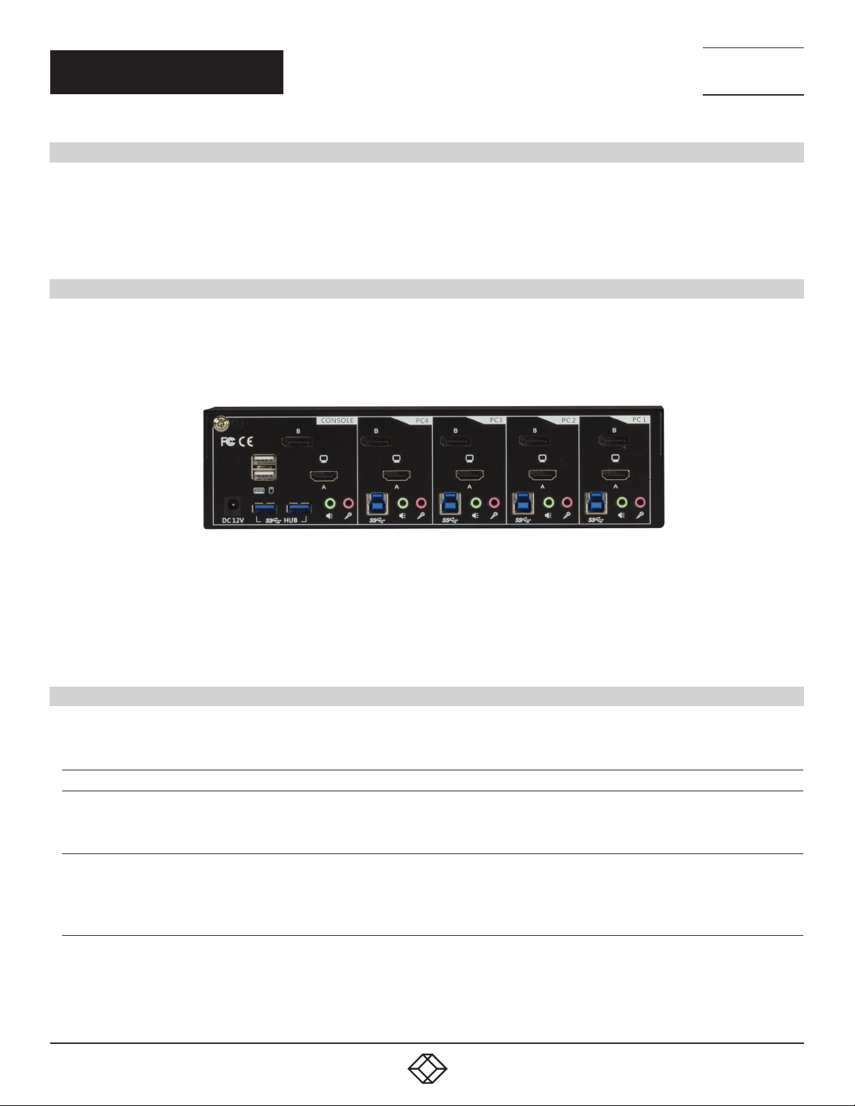
FIGURE 3-1. KV6224DPH – REAR VIEW
3. Connect each KVM PC port to a computer, using one HDMI 2.0 video cable (male-to-male) and one DP 1.2 video cable (male-to-male),
one USB cable (type A to type B), and one audio and mic combo cable (male-to-male).
4. Connect each of your USB devices to the USB hub ports (on the left).
You can now begin to use the KVM switch.
OPERATION COMMANDS QUICK REFERENCE CHART
OPERATION COMMANDS FOR HOTKEYS/FRONT-PANEL BUTTONS
COMMAND HOTKEYS
Select PC Port2 (Jointly
select PC port/ hub port
control/ audio and mic, if
binding is enabled)
Select Hub Port Control2
(Jointly select PC and hub
port control, if binding is
enabled)
Scr-Lock, Scr-Lock + “X”
X = 1–4 PC port Number
Scr-Lock, Scr-Lock +“Fx”
Fx = F1–F4 ( Fx is a Function Key)
x = 1–4 for Hub port number
1
FRONT-PANEL BUTTON DESCRIPTION
Press the corresponding button to
select the active PC port.
Press the button to toggle the
specific PC + USB hub port control.
(It works only if PC port/ hub port
control binding is enabled.)
Select the active PC port (Jointly
select PC port/ hub port control/
audio and mic, if binding is enabled)
Select the PC port that control all USB
hub ports
(Jointly select PC and hub port
control, if PC/hub port control binding
is enabled)
1. 8 7 7. 8 7 7. 2 2 6 9 BLACK BOX .COM
3
Page 4

QUICK START GUIDE
OPERATION COMMANDS FOR HOTKEYS/FRONT-PANEL BUTTONS (CONTINUED)
NEED HELP?
LEAV E TH E TEC H TO US
LIVE 24/7
TECHNICAL
SUPPORT
1. 8 7 7. 8 7 7. 2 2 6 9
COMMAND HOTKEYS
Scr-Lock, Scr-Lock +”Fy”
Select Audio and Mic Port
(Jointly select PC port and
audio and mic, if binding is
enabled)
Bind PC and Hub Port
Control Switching2 [Default]
Unbind PC and Hub Port
Control Switching2 [Default]
Bind PC and Audio and Mic
Switching
Unbind PC and Audio and
Mic Switching3 [Default]
Previous PC port2 (Jointly
select PC/ hub port control,
if binding is enabled)
Next PC port
Previous PC port Scr-Lock, Scr-Lock + ” ” (Backspace) —
Beep Sound On/Off Scr-Lock, Scr-Lock + “B” — Toggle on/off the beep sound
Define Hotkey Preceding
Autoscan Scr-Lock, Scr-Lock + “S” —
Autoscan with
Programmable Delay
Stop Auto Scan Press any key on keyboard Press any button Terminate Autoscan activity
DisplayPort Link Training Scr-Lock, Scr-Lock+”P” —
3
[Default]
2
3
Fy =F5–F6 (for 2-port) or F5–F8
(for 4-port) (Fy is a Function Key)
y = 5–6 (for 2-port) or 5–8 (for 4-port)
for Audio and Mic number
Scr-Lock, Scr-Lock + “Z” —
Scr-Lock, Scr-Lock + “X” —
Scr-Lock, Scr-Lock + “Q” —
Scr-Lock, Scr-Lock + “W” —
Scr-Lock, Scr-Lock + “” (Arrow Up) —
Scr-Lock, Scr-Lock + “” (Arrow Down) —
Scr-Lock, Scr-Lock + “H” + “y”
y=Scroll Lock, Caps Lock, ESC, F12,
Num Lock
Scr-Lock, Scr-Lock + “H” + “z”
z = 1>10’, 2>20’,3>30’, 4>40’, 5>50’,
6>60’, 7>70’, 8>80’, 9>90’, 0>100’
1
FRONT-PANEL BUTTON DESCRIPTION
Select the active audio and mic port
—
Press and hold down last button
(Button 2) till two beeps, release
the button, then press (y)
—
(Jointly select PC and audio and mic
port, if binding is enabled)
Enable the binding of PC port and
hub port control (Once this feature
is enabled, any pc and/or hub port
control switching is bound together)
(factory default)
Disable the binding of PC port and hub
port control switching
Enable the binding of PC port and
audio and mic switching. (Once this
feature is enabled, any PC and/or
audio and mic switching is bound
together) (factory default)
Disable the binding of PC port and
audio and mic
Select the previous connected PC port
(Jointly select PC/ hub port control, if
binding is enabled)
Select the next connected PC port
(Jointly select PC/ hub port control, if
binding is enabled)
Toggle between the previous port and
current port
Select the hotkey preceding sequence
among 5 alternative keys
Autoscan through every connected
port for quick screen browsing of each
port (scan delay = 5 sec.)
Autoscan with a user-defined delay
time within a range of 10 to 100
seconds
Toggles DisplayPort Link Training
ON/OFF
NOTES:
1. The USB keyboard hotkeys allow you a faster and broader control for your KVM switching operation in addition to the front-panel button.
If you have configured a hotkey preceding sequence other than two consecutive scroll locks, here you should change your hotkey
sequence accordingly. (For preceding sequence key configuration, please refer to ”Define Hotkey Preceding Sequence” in above table.)
2. When the binding of PC and USB hub port control switching is enabled by the hotkey sequence: ScrLk + ScrLk + Z, any PC and hub port
control switching are bound together. To remove this binding, use the hotkey sequence: ScrLk + ScrLk + X.
3. When the binding of PC and audio and mic switching is enabled by the hotkey sequence: ScrLk + ScrLk + Q, any PC and audio and mic
switching are bound together. To remove this binding, use the hotkey sequence: ScrLk + ScrLk + W.
4
1. 8 7 7. 8 7 7. 2 2 6 9 BLACK BOX .COM
Page 5

CHAPTER 1: SPECIFICATIONS
1. SPECIFICATIONS
TABLE 1-1. SPECIFICATIONS
SPECIFICATION KV6224DPH
Number of Ports (4)
Number of Consoles (2)
PC Keyboard/Mouse Connectors (4) USB Type B female
PC Video Connectors (4) HDMI 2.0 female, (4) DisplayPort 1.2 female
PC Audio/Mic (8) 3.5-mm audio/mic Jack female
Console Keyboard Connector (1) USB Type A female
Console Mouse Connector (1) USB Type A female
Console Monitor Connector (1) HDMI 2.0 female, (1) DisplayPort 1.2 female
USB Hub Ports (2) USB 3.0 Type A female (5 Gbps data transfer rates)
PC Selection Pushbuttons/Hotkeys
Beeper Yes
PC Port LEDs 4 (Green)
Hub Port LEDs 4 (Red)
Digital Display Resolution 3840 x 2180 @ 60 Hz
Keyboard and Mouse Emulation Yes (TTU)
Autoscan Delay Time 10 to 60 sec.
Power Adapter 12 VDC, 3 A
Weight 2.6 lb. (1.2 kg)
Dimensions 2.6" H x 3.9" W x 9.9" D (6.6 x 10.0 x 25.3 cm)
Safety/Emissions FCC, CE
NEED HELP?
LEAV E TH E TEC H TO US
LIVE 24/7
TECHNICAL
SUPPORT
1. 8 7 7. 8 7 7. 2 2 6 9
1. 8 7 7. 8 7 7. 2 2 6 9 BLACK BOX .COM
5
Page 6

NEED HELP?
LEAV E TH E TEC H TO US
LIVE 24/7
CHAPTER 2: OVERVIEW
2. OV ERVIE W
2.1 INTRODUCTION
The KV6224DPH 4-Port Dual-Monitor HDMI 2.0/DisplayPort 1.2 USB 3.0 (5 Gbps data transfer rates), Audio KVM Switch is designed
specifically for sharing two 4K monitors between four multimedia computers with dual-monitor HDMI/DP display. It is the perfect
solution for computers using mixed DisplayPort/HDMI graphics cards.
With KV6224DPH, you can fully control four dual-monitor PCs using only one keyboard, mouse and two 4K monitors; essential for saving
valuable desktop space.
This dual-monitor HDMI/DisplayPort KVM switch supports two monitors at 3840 x 2160/4K 60 Hz resolution for maximum convenience
in adapting to your display requirements.
True Transparent USB Emulation Technology allows complete versatility in dealing with the advanced functional requirements of today’s
keyboards and mice. From gaming mice/keyboards to advanced business mice/keyboards, users will appreciate what this technology
can do for them.
Share all your USB peripheral devices with ease using the separate built-in 2-port USB 3.0 hub (5Gbps data transfer rates) between each
connected computer. The USB hub automatically switches the connected USB peripheral to the selected computer saving you the cost
of adding additional peripherals.
Independent audio switching lets users freeze audio while simultaneously working on a different system. With 3.5 mm stereo audio input
for each channel, two-way audio support for speakers and microphone is available; perfect for sound design or editing applications.
TECHNICAL
SUPPORT
1. 8 7 7. 8 7 7. 2 2 6 9
2.2 FEATURES
Mixed input/output; ideal for mixed video graphics cards
4-port dual monitor HDMI 2.0/DisplayPort 1.2 USB 3.0 KVM switch with audio and microphone switching
(2) additional USB 3.0 hub ports (5 Gbps data transfer rates) for sharing high-speed USB devices
True transparent USB (TTU) emulation technology full driver supports advanced USB keyboards and mice
USB 3.0/USB 2.0/USB 1.1 specification compliant (up to 5 Gbps data transfer rates)
Supports digital video resolution up to 3840 x 2160 at 60 Hz (dual monitors)
Independent/simultaneous PC/hub/aduio and mic port selection
Multi-platform support for Windows
®
XP/7/8/10, Linux®, and Mac® OS
Switching by front-panel pushbuttons and keyboard hotkeys
Two-channel stereo audio
Low power consumption
Firmware upgradable via USB port
TAA compliant
2.3 WHAT’S INCLUDED
Your package should include the following items. If anything is missing or damaged, contact Black Box Technical Support
at 877-877-2269 or info@blackbox.com
(1) KV6224DPH unit
(1) 12-VDC power adapter
6
1. 8 7 7. 8 7 7. 2 2 6 9 BLACK BOX .COM
Page 7

CHAPTER 2: OVERVIEW
2.4 HARDWARE DESCRIPTION
KV6224DPH
9 8 9 8 9 8 9 8
NEED HELP?
LEAV E TH E TEC H TO US
LIVE 24/7
TECHNICAL
SUPPORT
1. 8 7 7. 8 7 7. 2 2 6 9
10 10 10 10
FIGURE 2-1. FRONT PANEL OF THE KV6224DPH
4, 5 6B 6A 2B 2A 2B 2A 2B 2A 2B 2A
11 7 7 3 3 1 3 3 1 3 3 1 3 3 1 3 3
FIGURE 2-2. BACK PANEL OF THE K V6224DPH
1. 8 7 7. 8 7 7. 2 2 6 9 BLACK BOX .COM
7
Page 8

CHAPTER 2: OVERVIEW
TABLE 2-1. KV6224DPH COMPONENTS
NUMBER IN FIGURE 2-1 OR 2-2 COMPONENT DESCRIPTION
1 PC Keyboard/Mouse Connectors (4) USB Type B female
2A PC Video Connectors (2) HDMI female
2B PC Video Connectors (2) DisplayPort female
3
4 Console Keyboard Connector (1) USB Type A female
5
6
7
8 PC Selection Pushbuttons/Hotkeys
9 PC Port LEDs 4 (Green)
10 Hub Port LEDs 4 (Red)
PC Audio/Mic (8) 3.5-mm audio/mic jack female
Console Mouse Connector (1) USB Type A female
Console Monitor Connector (2) HDMI female, (2) DisplayPort female
USB Hub Ports (2) USB 3.0 Type A female
NEED HELP?
LEAV E TH E TEC H TO US
LIVE 24/7
TECHNICAL
SUPPORT
1. 8 7 7. 8 7 7. 2 2 6 9
8
1. 8 7 7. 8 7 7. 2 2 6 9 BLACK BOX .COM
Page 9

NEED HELP?
LEAV E TH E TEC H TO US
LIVE 24/7
CHAPTER 3: INSTALLATION
TECHNICAL
SUPPORT
1. 8 7 7. 8 7 7. 2 2 6 9
3. I N S TA LL AT ION
1. Power up your KVM Switch by connecting the external power adapter to it.
2. Connect the shared USB keyboard, mouse, two monitors, speaker/headphone and microphone to corresponding ports on console
section of the KVM Switch.
NOTE: The two left-side white USB ports are for keyboard and mouse and two blue USB 3.0 ports are for other USB devices.
FIGURE 3-1. KV6224DPH – REAR VIEW
3. Connect each KVM PC port to a computer, using one HDMI 2.0 video cable (male-to-male) and one DP 1.2 video cable (male-to-male),
one USB cable (type A to type B), and one audio and mic combo cable (male-to-male).
4. Connect each of your USB devices to the USB hub ports (on the left).
You can now begin to use the KVM switch.
FIGURE 3-2. CONNECTION ILLUSTRATION
1. 8 7 7. 8 7 7. 2 2 6 9 BLACK BOX .COM
9
Page 10

NEED HELP?
LEAV E TH E TEC H TO US
LIVE 24/7
CHAPTER 4: OPERATION
4. OPERATION
A keyboard hotkey sequence consists of at least three specific keystrokes:
Hotkey sequence = [ScrLk]* + [ScrLk] * + Command key(s)
* User-definable = SCROLL LOCK, CAPS, ESC, F12 or NUM LOCK
Hotkey preceding sequence configuration: For users who want to use a preceding sequence other than two consecutive Scroll Locks,
there is also one convenient way to configure it.
1. Press ScrollLock + ScrollLock + H, then two beeps will signal readiness for new preceding sequence selection (or Press and hold down
the last front-panel button [Button 2 or Button 4] until you hear two beeps, then release the button.)
2. Select and press the key you would like to use as your preceding sequence (SCROLL LOCK, CAPS, ESC, F12 or NUM LOCK keys
are available for selection) and you’ll hear a beep for selection confirmation. Now you can use the new preceding sequence to execute
your hotkey commands.
NOTE: Press each keystroke within a hotkey sequence within 2 seconds. Otherwise, the hotkey sequence will not be validated.
NOTE: Hotkey sequence = [ScrLk]* + [ScrLk] * + Command key(s)
* User-definable Preceding sequence = SCROLL LOCK, CAPS, ESC, F12, or NUM LOCK
TECHNICAL
SUPPORT
1. 8 7 7. 8 7 7. 2 2 6 9
TABLE 4-1. OPERATION COMMANDS FOR HOTKEYS/FRONT-PANEL BUTTONS
COMMAND HOTKEYS
Select PC Port
select PC port/ hub port
control/ audio and mic, if
binding is enabled)
Select Hub Port Control
(Jointly select PC and hub
port control, if binding is
enabled)
Select Audio and Mic Port
(Jointly select PC port and
audio and mic, if binding is
enabled)
Bind PC and Hub Port
Control Switching2 [Default]
2
(Jointly
Scr-Lock, Scr-Lock + “X”
X = 1–4 PC port Number
2
Scr-Lock, Scr-Lock +“Fx”
Fx = F1–F4 ( Fx is a Function Key)
x = 1–4 for Hub port number
Scr-Lock, Scr-Lock +”Fy”
3
Fy =F5–F6 (for 2-port) or F5–F8
(for 4-port) (Fy is a Function Key)
y = 5–6 (for 2-port) or 5–8 (for 4-port)
for Audio and Mic number
Scr-Lock, Scr-Lock + “Z” —
NOTES:
1. The USB keyboard hotkeys allow you a faster and broader control for your KVM switching operation in addition to the front-panel
button. If you have configured a hotkey preceding sequence other than two consecutive scroll locks, here you should change
your hotkey sequence accordingly. (For preceding sequence key configuration, please refer to ”Define Hotkey Preceding Sequence”
in above table.)
2. When the binding of PC and USB hub port control switching is enabled by the hotkey sequence: ScrLk + ScrLk + Z, any PC
and hub port control switching are bound together. To remove this binding, use the hotkey sequence: ScrLk + ScrLk + X.
3. When the binding of PC and audio and mic switching is enabled by the hotkey sequence: ScrLk + ScrLk + Q, any PC and audio and mic
switching are bound together. To remove this binding, use the hotkey sequence: ScrLk + ScrLk + W.
1
FRONT-PANEL BUTTON DESCRIPTION
Press the corresponding button to
select the active PC port.
Press the button to toggle the
specific PC + USB hub port control.
(It works only if PC port/ hub port
control binding is enabled.)
—
Select the active PC port (Jointly
select PC port/ hub port control/
audio and mic, if binding is enabled)
Select the PC port that control all USB
hub ports
(Jointly select PC and hub port
control, if PC/hub port control binding
is enabled)
Select the active audio and mic port
(Jointly select PC and audio and mic
port, if binding is enabled)
Enable the binding of PC port and
hub port control (Once this feature
is enabled, any pc and/or hub port
control switching is bound together)
(factory default)
10
1. 8 7 7. 8 7 7. 2 2 6 9 BLACK BOX .COM
Page 11

CHAPTER 4: OPERATION
TABLE 4-1 (CONTINUED). OPERATION COMMANDS FOR HOTKEYS/FRONT-PANEL BUTTONS
NEED HELP?
LEAV E TH E TEC H TO US
LIVE 24/7
TECHNICAL
SUPPORT
1. 8 7 7. 8 7 7. 2 2 6 9
COMMAND HOTKEYS
Unbind PC and Hub Port
Control Switching2 [Default]
Bind PC and Audio and Mic
Switching3 [Default]
Unbind PC and Audio and
Mic Switching3 [Default]
Previous PC port2 (Jointly
select PC/ hub port control,
if binding is enabled)
Next PC port
Previous PC port Scr-Lock, Scr-Lock + ” ” (Backspace) —
Beep Sound On/Off Scr-Lock, Scr-Lock + “B” — Toggle on/off the beep sound
Define Hotkey Preceding
Autoscan Scr-Lock, Scr-Lock + “S” —
Autoscan with
Programmable Delay
Stop Auto Scan Press any key on keyboard Press any button Terminate Autoscan activity
DisplayPort Link Training Scr-Lock, Scr-Lock+”P” —
2
Scr-Lock, Scr-Lock + “X” —
Scr-Lock, Scr-Lock + “Q” —
Scr-Lock, Scr-Lock + “W” —
Scr-Lock, Scr-Lock + “” (Arrow Up) —
Scr-Lock, Scr-Lock + “” (Arrow Down) —
Scr-Lock, Scr-Lock + “H” + “y”
y=Scroll Lock, Caps Lock, ESC, F12,
Num Lock
Scr-Lock, Scr-Lock + “H” + “z”
z = 1>10’, 2>20’,3>30’, 4>40’, 5>50’,
6>60’, 7>70’, 8>80’, 9>90’, 0>100’
1
FRONT-PANEL BUTTON DESCRIPTION
Disable the binding of PC port and hub
port control switching
Enable the binding of PC port and
audio and mic switching. (Once this
feature is enabled, any PC and/or
audio and mic switching is bound
together) (factory default)
Disable the binding of PC port and
audio and mic
Select the previous connected PC port
(Jointly select PC/ hub port control, if
binding is enabled)
Select the next connected PC port
(Jointly select PC/ hub port control, if
binding is enabled)
Toggle between the previous port and
current port
Press and hold down last button
(Button 2) till two beeps, release
the button, then press (y)
—
Select the hotkey preceding sequence
among 5 alternative keys
Autoscan through every connected
port for quick screen browsing of each
port (scan delay = 5 sec.)
Autoscan with a user-defined delay
time within a range of 10 to 100
seconds
Toggles DisplayPort Link Training
ON/OFF
NOTES:
1. The USB keyboard hotkeys allow you a faster and broader control for your KVM switching operation in addition to the front-panel
button. If you have configured a hotkey preceding sequence other than two consecutive scroll locks, here you should change your
hotkey sequence accordingly. (For preceding sequence key configuration, please refer to ”Define Hotkey Preceding Sequence” in
above table.)
2. When the binding of PC and USB hub port control switching is enabled by the hotkey sequence: ScrLk + ScrLk + Z, any PC and hub port
control switching are bound together. To remove this binding, use the hotkey sequence: ScrLk + ScrLk + X.
3. When the binding of PC and audio and mic switching is enabled by the hotkey sequence: ScrLk + ScrLk + Q, any PC and audio and mic
switching are bound together. To remove this binding, use the hotkey sequence: ScrLk + ScrLk + W.
1. 8 7 7. 8 7 7. 2 2 6 9 BLACK BOX .COM
11
Page 12

NEED HELP?
LEAV E TH E TEC H TO US
LIVE 24/7
APPENDIX A: REGULATORY INFORMATION
A.1 FCC STATEMENT
This equipment has been tested and found to comply with the regulations for a Class B digital device, pursuant to Part 15 of
the FCC Rules. These limits are designed to provide reasonable protection against harmful interference when the equipment
is operated in a commercial environment. This equipment generates, uses, and can radiate radio frequency energy and, if not
installed and used in accordance with this Quick Installation Guide, may cause harmful interference to radio communications.
Operation of this equipment in a residential area is likely to cause harmful interference in which case, the user will be required to
correct the interference at his/her own expense.
A.2 CE STATEMENT
This is a Class B product in a domestic environment, this product may cause radio interference, in which case the user may be
required to take adequate measures.
A.3 ROHS
This product is RoHS compliant.
TECHNICAL
SUPPORT
1. 8 7 7. 8 7 7. 2 2 6 9
12
1. 8 7 7. 8 7 7. 2 2 6 9 BLACK BOX .COM
Page 13

NEED HELP?
LEAV E TH E TEC H TO US
LIVE 24/7
APPENDIX A: REGULATORY INFORMATION
A.4 NOM STATEMENT
1. Todas las instrucciones de seguridad y operación deberán ser leídas antes de que el aparato eléctrico sea operado.
2. Las instrucciones de seguridad y operación deberán ser guardadas para referencia futura.
3. Todas las advertencias en el aparato eléctrico y en sus instrucciones de operación deben ser respetadas.
4. Todas las instrucciones de operación y uso deben ser seguidas.
5. El aparato eléctrico no deberá ser usado cerca del agua—por ejemplo, cerca de la tina de baño, lavabo, sótano mojado o cerca de
una alberca, etc.
6. El aparato eléctrico debe ser usado únicamente con carritos o pedestales que sean recomendados por el fabricante.
7. El aparato eléctrico debe ser montado a la pared o al techo sólo como sea recomendado por el fabricante.
8. Servicio—El usuario no debe intentar dar servicio al equipo eléctrico más allá a lo descrito en las instrucciones de operación.
Todo otro servicio deberá ser referido a personal de servicio calificado.
9. El aparato eléctrico debe ser situado de tal manera que su posición no interfiera su uso. La colocación del aparato eléctrico
sobre una cama, sofá, alfombra o superficie similar puede bloquea la ventilación, no se debe colocar en libreros o gabinetes que
impidan el flujo de aire por los orificios de ventilación.
10. El equipo eléctrico deber ser situado fuera del alcance de fuentes de calor como radiadores, registros de calor, estufas u otros
aparatos (incluyendo amplificadores) que producen calor.
11. El aparato eléctrico deberá ser connectado a una fuente de poder sólo del tipo descrito en el instructivo de operación, o como
se indique en el aparato.
12. Precaución debe ser tomada de tal manera que la tierra fisica y la polarización del equipo no sea eliminada.
13. Los cables de la fuente de poder deben ser guiados de tal manera que no sean pisados ni pellizcados por objetos colocados
sobre o contra ellos, poniendo particular atención a los contactos y receptáculos donde salen del aparato.
14. El equipo eléctrico debe ser limpiado únicamente de acuerdo a las recomendaciones del fabricante.
15. En caso de existir, una antena externa deberá ser localizada lejos de las lineas de energia.
16. El cable de corriente deberá ser desconectado del cuando el equipo no sea usado por un largo periodo de tiempo.
17. Cuidado debe ser tomado de tal manera que objectos liquidos no sean derramados sobre la cubierta u orificios de ventilación.
18. Servicio por personal calificado deberá ser provisto cuando:
A: El cable de poder o el contacto ha sido dañado; u
B: Objectos han caído o líquido ha sido derramado dentro del aparato;o
C: El aparato ha sido expuesto a la lluvia; o
D: El aparato parece no operar normalmente o muestra un cambio en su desempeño; o
E: El aparato ha sido tirado o su cubierta ha sido dañada.
TECHNICAL
SUPPORT
1. 8 7 7. 8 7 7. 2 2 6 9
1. 8 7 7. 8 7 7. 2 2 6 9 BLACK BOX .COM
13
Page 14

NEED HELP?
LEAV E TH E TEC H TO US
LIVE 24/7
APPENDIX B: DISCLAIMER/TRADEMARKS
TECHNICAL
SUPPORT
1. 8 7 7. 8 7 7. 2 2 6 9
B.1 DISCLAIMER
Black Box Corporation shall not be liable for damages of any kind, including, but not limited to, punitive, consequential or cost of cover
damages, resulting from any errors in the product information or specifications set forth in this document and Black Box Corporation
may revise this document at any time without notice.
B.2 TRADEMARKS USED IN THIS MANUAL
Black Box and the Black Box logo type and mark are registered trademarks of Black Box Corporation.
Any other trademarks mentioned in this manual are acknowledged to be the property of the trademark owners.
14
1. 8 7 7. 8 7 7. 2 2 6 9 BLACK BOX .COM
Page 15

NOTES
NEED HELP?
LEAV E TH E TEC H TO US
LIVE 24/7
TECHNICAL
SUPPORT
1. 8 7 7. 8 7 7. 2 2 6 9
1. 8 7 7. 8 7 7. 2 2 6 9 BLACK BOX .COM
15
Page 16

NOTES
NEED HELP?
LEAV E TH E TEC H TO US
LIVE 24/7
TECHNICAL
SUPPORT
1. 8 7 7. 8 7 7. 2 2 6 9
16
1. 8 7 7. 8 7 7. 2 2 6 9 BLACK BOX .COM
Page 17

NOTES
NEED HELP?
LEAV E TH E TEC H TO US
LIVE 24/7
TECHNICAL
SUPPORT
1. 8 7 7. 8 7 7. 2 2 6 9
1. 8 7 7. 8 7 7. 2 2 6 9 BLACK BOX .COM
17
Page 18

NEED HELP?
LEAVE THE TECH TO US
LIVE 24/7
TECHNICAL
SUPPORT
1.877.8 7 7. 2 2 6 9
© COPYRIGHT 2021. BLACK BOX CORPORATION. ALL RIGHTS RESERVED.
KV6224DPH_QSG_USER_REV1.PDF
 Loading...