

Page 1

Page 2

THE SERVSWITCH™ FAMILY
1
Welcome to the ServSwitch™ Family!
Thank you for purchasing a BLACK BOX® ServSwitch™ Brand KVM switch! We
appreciate your business, and we think you’ll appreciate the many ways that
your new ServSwitch keyboard/video/mouse switch will save you money, time,
and effort.
That’s because our ServSwitch family is all about breaking away from the
traditional, expensive model of computer management. You know, the one-sizefits-all-even-if-it-doesn’t model that says, “One computer gets one user station,
no more, no less.” Why not a single user station (monitor, keyboard, and mouse)
for multiple computers—even computers of different platforms? Why not a pair
of user stations, each of which can control multiple computers? Why not multiple
user stations for the same computer?
With our ServSwitch products, there’s no reason why not. We carry a broad line
of robust solutions for all these applications. Do you have just two PCs, and
need an economical alternative to keeping two monitors, keyboards, and mice
on your desk? Or do you need to share dozens of computers, including a mix of
IBM® PC, RS/6000®, Apple® Macintosh®, Sun Microsystems®, and SGI®
compatibles among multiple users with different access levels? Does your
switch have to sit solidly on a worktable and use regular everyday cables? Or
does it have to be mounted in an equipment rack and use convenient many-toone cables? No matter how large or small your setup is, no matter how simple
or how complex, we’re confident we have a ServSwitch system that’s just right
for you.
The ServSwitch ™ family from Black Box—the one-stop answer for all your
KVM-switching needs!
This manual will tell you all about your new ServSwitch™, including how to
install, operate, and troubleshoot it.
The ServSwitch product codes covered in this manual are:
KV3104MN-R4
KV5004MN-R2
Page 3

SERVSWITCH™
2
TRADEMARKS USED IN THIS MANUAL
BLACK BOX and the logo are registered trademarks, and ServSwitch, and
ServSwitch Console plus are trademarks, of Black Box Corporation.
Apple, Mac, and Macintosh are registered trademarks of Apple Computer, Inc.
Compaq and Alpha are registered trademarks, and DEC is a trademark, of Compaq
Computer Corporation.
HP is a registered trademark of Hewlett-Packard.
IBM, PC/AT, PS/2, RS/6000, and ThinkPad are registered trademarks, and PC/XT is a
trademark, of International Business Machines Corporation.
Microsoft, HyperTerminal, IntelliMouse, Windows, and Windows NT are registered
trademarks or trademarks of Microsoft Corporation in the United States and/or
other countries.
Sun and Sun Microsystems are registered trademarks of Sun Microsystems, Inc. in the
United States and other countries.
Any other trademarks mentioned in this manual are acknowledged to be the property of
the trademark owners.
Page 4

FCC/IC STATEMENTS, EU DECLARATION OF CONFORMITY
3
FEDERAL COMMUNICATIONS COMMISSION AND INDUSTRY
CANADA
RADIO-FREQUENCY INTERFERENCE STATEMENTS
This equipment generates, uses, and can radiate radio frequency energy and if
not installed and used properly, that is, in strict accordance with the
manufacturer’s instructions, may cause interference to radio communication. It
has been tested and found to comply with the limits for a Class A digital device
in accordance with the specifications of Part 15 of FCC rules, which are
designed to provide reasonable protection against such interference when the
equipment is operated in a commercial environment. Operation of this
equipment in a residential area is likely to cause interference, in which case the
user at his own expense will be required to take whatever measures may be
necessary to correct the interference.
Changes or modifications not expressly approved by the party responsible for
compliance could void the user’s authority to operate the equipment. This digital
apparatus does not exceed the Class A limits for radio noise regulation of
industry Canada.
Le présent appareil numérique n’émet pas de bruits radioélectriques dépassant
les limites applicables aux appareils numériques de la classe A prescrites dans
le Règlement sur le brouillage radioélectrique publié par Industrie Canada.
EUROPEAN UNION DECLARATION OF CONFORMITY
ACCORDING TO COUNCIL DIRECTIVE 89/336EEC
This equipment is in conformity with the
requirements of the European EMC directive
89/336/EEC
72/21/EEC
EN55022: (Class A, 1998)
EN55024 (1998)
CISPR22 (1995)
Page 5

SERVSWITCH™
4
OM STATEMENT
NORMAS OFICIALES MEXICANAS (NOM)
ELECTRICAL SAFETY STATEMENT
INSTRUCCIONES DE SEGURIDAD
1. Todas las instrucciones de seguridad y operación deberán ser leídas antes de
que el aparato eléctrico sea operado.
2. Las instrucciones de seguridad y operación deberán ser guardadas para
referencia future.
3. Todas las advertencias en el aparato eléctrico y en sus instrucciones de
operación deben ser respetadas
4. Todas las instrucciones de operación y uso deben ser seguidas
5. El aparato eléctrico no deberá ser usado cerca del agua—por ejemplo, cerca
de la tina de baño, lavabo, sótano mojado o cerca de una alberca, etc.
6. El aparato eléctrico debe ser usado únicamente con carritos o pedestales que
sean recomendados por el fabricante.
7. El aparato eléctrico debe ser montado a la pared o al techo sólo como sea
recomendado por el fabricante
8. Servicio—El usuario no debe intentar dar servicio al equipo eléctrico más allá
a lo descrito en las instrucciones de operación. Todo otro servicio deberá ser referido
a personal de servicio calificado.
9. El aparato eléctrico debe ser situado de tal manera que su posición no
interfiera su uso. La colocación del aparato eléctrico sobre una cama, sofá,
alfombra o superficie similar puede bloquea la ventilación, no se debe colocar
en libreros o gabinetes que impidan el flujo de aire por los orificios de
ventilación
10. El equipo eléctrico deber ser situado fuera del alcance de fuentes de calor
como radiadores, registros de calor, estufas u otros aparatos (incluyendo
amplificadores) que producen calor.
11. El aparato eléctrico deberá ser connectado a una fuente de poder sólo del
tipo descrito en el instructivo de operación, o como se indique en el aparato
Page 6

NOM STATEMENT .
5
12. Precaución debe ser tomada de tal manera que la tierra fisica y la polarización del
equipo no sea eliminada.
13. Los cables de la fuente de poder deben ser guiados de tal manera que no
sean pisados ni pellizcados por objetos colocados sobre o contra ellos,
poniendo particular atención a los contactos y receptáculos donde salen del
aparato.
14. El equipo eléctrico debe ser limpiado únicamente de acuerdo a las
recomendaciones del fabricante.
15. En caso de existir, una antena externa deberá ser localizada lejos de las
lineas de energia.
16. El cable de corriente deberá ser desconectado del cuando el equipo no sea
usado por un largo periodo de tiempo.
17. Cuidado debe ser tomado de tal manera que objectos liquidos no sean
derramados sobre la cubierta u orificios de ventilación.
18. Servicio por personal calificado deberá ser provisto cuando:
A: El cable de poder o el contacto ha sido dañado; u
B: Objectos han caído o líquido ha sido derramado dentro del aparato; o
C: El aparato ha sido expuesto a la lluvia; o
D: El aparato parece no operar normalmente o muestra un cambio en su
desempeño; o
E: El aparato ha sido tirado o su cubierta ha sido dañada.
Page 7

SERVSWITCH™
6
Contents
Disclaimer.........................................................................................................................7
Introduction.......................................................................................................................7
Features.......................................................................................................................8
Compatibility.................................................................................................................8
Package contents.........................................................................................................9
System overview...............................................................................................................9
KVM station..................................................................................................................9
CPU connection............................................................................................................9
Audio features ..............................................................................................................9
ServSwitch model...........................................................................................................10
ServSwitch model (rear)..................................................................................................11
Cables ............................................................................................................................12
ServSwitch to KVM station cables...............................................................................12
ServSwitch to CPU cables..........................................................................................12
ServSwitch Master to Slave unit cables ......................................................................12
Keyboard command usage.........................................................................................15
Organizing the system.....................................................................................................16
Installation – Single unit ..................................................................................................16
Connecting the KVM station........................................................................................16
Apply power................................................................................................................16
Connecting the computers..........................................................................................17
Installation – Cascading units..........................................................................................19
Connecting “Slave” units.............................................................................................20
Connecting the computers..........................................................................................20
Selecting a computer from the front panel...................................................................22
Selecting a computer using keyboard commands.......................................................22
Selecting a computer through the RS232 port.............................................................22
Reset to factory defaults.............................................................................................22
Rack mounting............................................................................................................22
Firmware update.........................................................................................................23
Safety and EMC Regulatory Statements.....................................................................28
Figures
Figure 1. ServSwitch model...............................................................................10
Figure 2. Rear panel..........................................................................................11
Figure 3. Single Unit installation ........................................................................18
Figure 4. Cascading units..................................................................................21
Tables
Figure 1. ServSwitch model...............................................................................10
Figure 2. Rear panel..........................................................................................11
Figure 3. Single Unit installation ........................................................................18
Figure 4. Cascading units..................................................................................21
Appendices
Appendix A. Initial factory settings...................................................................................30
Appendix B. Parts and cables .........................................................................................31
Appendix C. General Specifications ................................................................................32
Appendix D. Rack mount instructions..............................................................................33
Appendix E. Rack mount illustration................................................................................33
Appendix F. Keyboard mapping......................................................................................34
Appendix G. Video distance capability.............................................................................35
Page 8
INTRODUCTION
7
Disclaimer
While every precaution has been taken in the preparation of this manual, the
manufacturer assumes no responsibility for errors or omissions. Neither does
the manufacturer assume any liability for damages resulting from the use of
information contained herein. The manufacturer reserves the right to change
the specifications, functions, or circuitry of the product without notice.
The manufacturer cannot accept liability for damages due to misuse of the
product or other circumstances outside the manufacturer’s control. The
manufacturer will not be responsible for any loss, damage, or injury arising
directly or indirectly from the use of this product.
Introduction
Thank your for choosing the Black Box ® ServSwitch™ professional KVM
switch. The ServSwitch represents the latest technology in single user,
keyboard-monitor-mouse switching. The ServSwitch has proven to be a
valuable and dependable investment for users that have the need to access
multiple computer systems from a single KVM station.
The ServSwitch supports either PC/Unix systems, the ServSwitch Ultra (multiplatform) supports PC, Apple, Sun, USB, and Unix) systems. Switching to a
connected computer can be done by simple keyboard commands, selecting the
computer from the front panel, or through the RS/232 port.
All ServSwitch models can easily be expanded by chaining the units together
and configuring the system. The 4 port unit can be expanded to 16 computers.
Before performing any installation or configuration, please refer to the safety
section of this manual.
About this manual
This manual covers the installation and operation of the ServSwitch and
the ServSwitch Ultra. The ServSwitch models support PC and Unix, The
ServSwitch Ultra is a multi-platform model that supports PCs, Unix, Sun, IBM
RS/6000, DEC, HP, SGI, Apple, and audio.
A Keyboard, Video monitor, and Mouse are referred to
throughout this manual as a KVM station.
Page 9
SERVSWITCH™
8
Features
n Access up to 4 computers (16 computers in an expanded topology) from
one KVM station
n Available in PC/Unix or Multi-Platform models.
n Cable lengths up to 100 feet using coax cabling
n Video resolution up to 1600 x 1280
n Switch to a computer from the keyboard, the front panel switches, or the
RS/232 port
n Multi-platform models convert PC, Unix, Apple, or Sun keyboard and mouse
data to any platform
n Pre-configuration feature allows for the installation of a computer or server
without removing power
n Full keyboard and mouse emulation for automatic and simultaneous booting
n Flash memory with free base firmware upgrades available from our web site
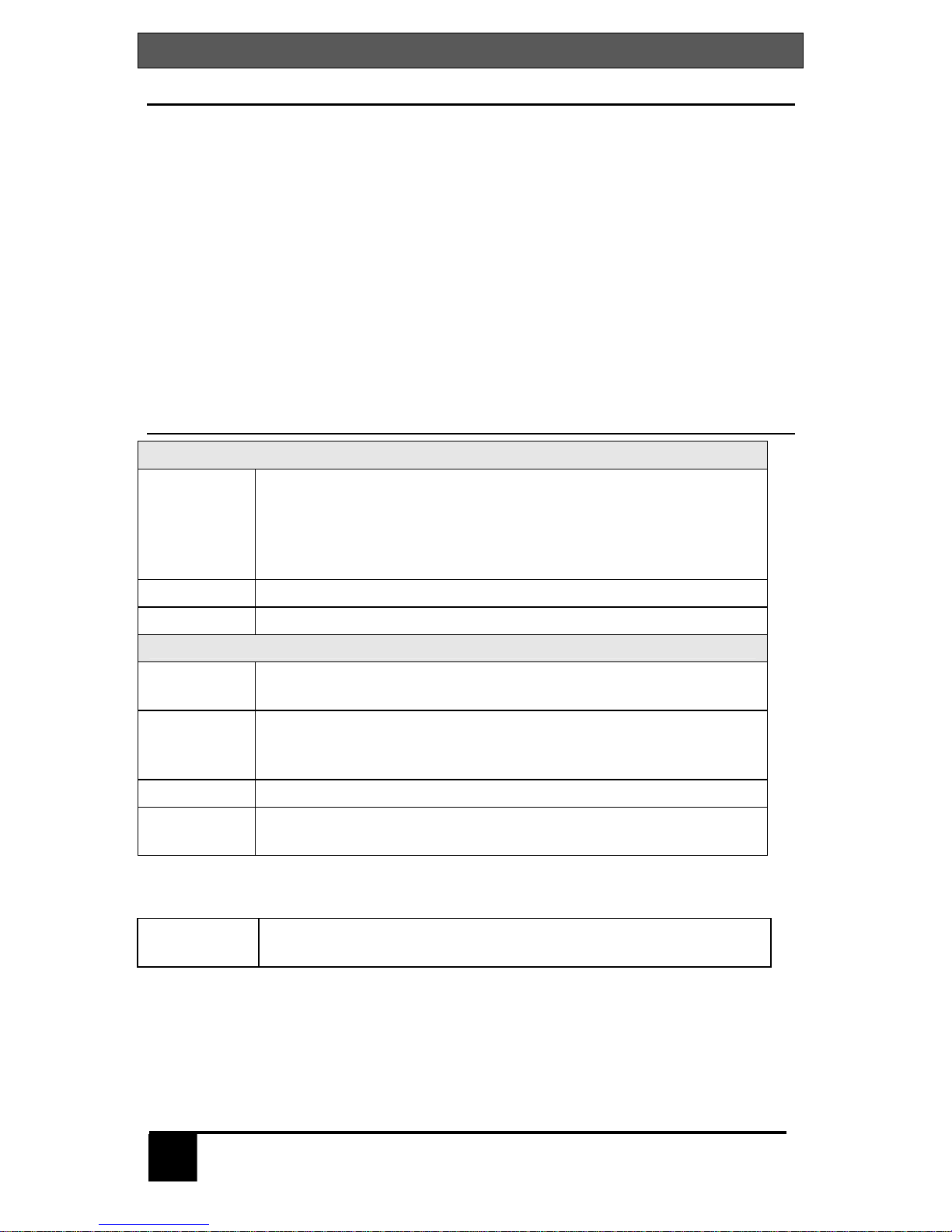
Compatibility
KVM compatibility
Keyboards PC, Unix, and most US and foreign QWERTY keyboards,
Japanese and Korean keyboards with or without Windows
keys, 101, 102, 104, 105, 106, 109, Sun. Some older XT/AT
auto-sensing or single mode keyboards may not be
compatible
Monitors VGA, SVGA, XGA, Composite
Mice Standard PS/2, PS/2 wheel, Sun
CPU compatibility
Computers Industry standard PCs, Unix systems, Sun, IBM RS/6000,
DEC, HP, SGI, Apple, and others
Keyboards Standard PC mode 1, 2, or 3 in PS/2 or AT, USB, Sun, Apple
ADB*. Some older XT/AT auto-sensing or single mode
keyboards may not be compatible
Monitors VGA, SVGA, XGA, Composite, Sync-of-green
Mice Standard PS/2, PS/2 wheel, Serial (2 or 3 button), USB, Sun,
Apple ADB*
* * Requires use of translator: KV99MCON – MAC
KV99SCON – SUN
Audio
Devices***
Audio speakers
Microphone
*** Available on ServSwitch Ultra model only
Page 10

INTRODUCTION
9
Package contents
The package contents consists of the following:
n The ServSwitch unit
n Power adapter
n DB9F to RJ12 adapter and cable
n Installation and operations manual
CPU, KVM, and expansion cables are usually ordered separately. If the
package contents are not correct, contact Black Box so the problem can be
quickly resolved.
Black Box web site
Visit out web site at www.blackbox.com for additional information on the
ServSwitch and other products offered by Black Box that are designed for data
center applications, classroom environments, and many other switching
applications.
System overview
The ServSwitch and ServSwitch Ultra are designed to provide seamless,
trouble-free switching from a single KVM station to any connected computer or
server. You can switch to any of the connected computers by simple keyboard
commands, the front panel – or + buttons, or from a computer terminal or
standalone PC connected to the RS/232 serial port (not connected to a CPU
port).
If your system demands are greater than a single unit can provide, the
ServSwitch can be easily expanded to connect up to 16 computers by chaining
units together with expansion cables.
KVM station
A KVM station consisting of a keyboard, monitor, and mouse connects to the
DB25F connector labeled MONITOR/KEYBORD/MOUSE.
CPU connection
All CPU connectors are DB25F. The CPUs are connected using a CPU cable
designed to interface with the CPU keyboard, monitor, and mouse ports. A CPU
cable is needed for each connected computer.
Audio features
The ServSwitch Ultra supports full stereo audio using a special CPU cable that
has a 3.5mm stereo connector for connection directly to a CPUs sound card and
a special KVM cable that connects to a pair of computer speakers or
headphones.
Page 11
SERVSWITCH™
10
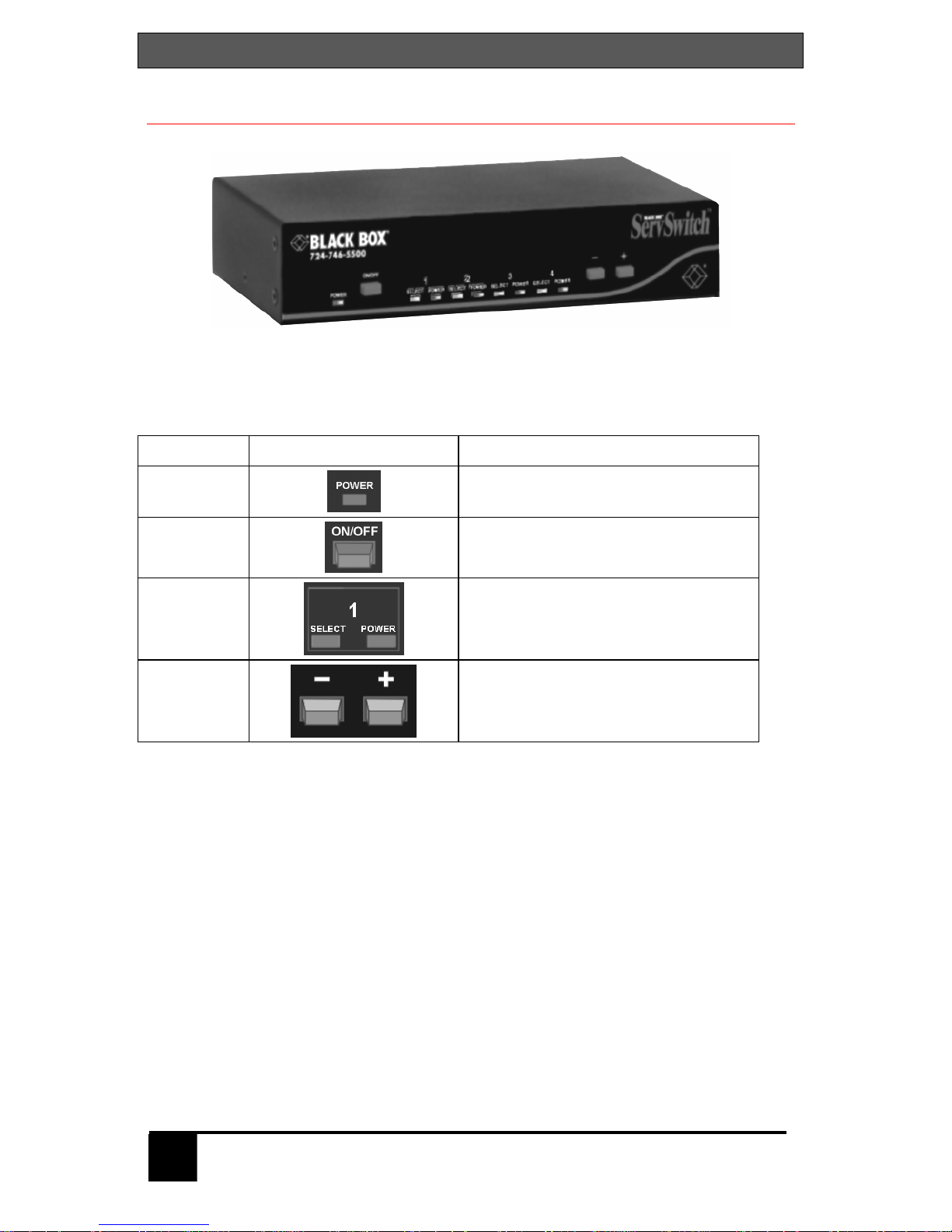
ServSwitch model
Figure 1. ServSwitch model
Label Description
Power
Power LED - Green when unit is
on
ON/OFF
“M” chassis only – In = ON
Out = OFF
LEDs
Indicator LEDs; Numbered pairs of
LEDs shows status and power of
connected computers
- and +
Switches*
- Connects to the previous CPU
+ Connects to the next CPU
* The - and + switches are used when:
n upgrading the firmware
n resetting the unit to factory defaults
n running diagnostics.
Table 1. Front panel
Page 12
MODELS
11
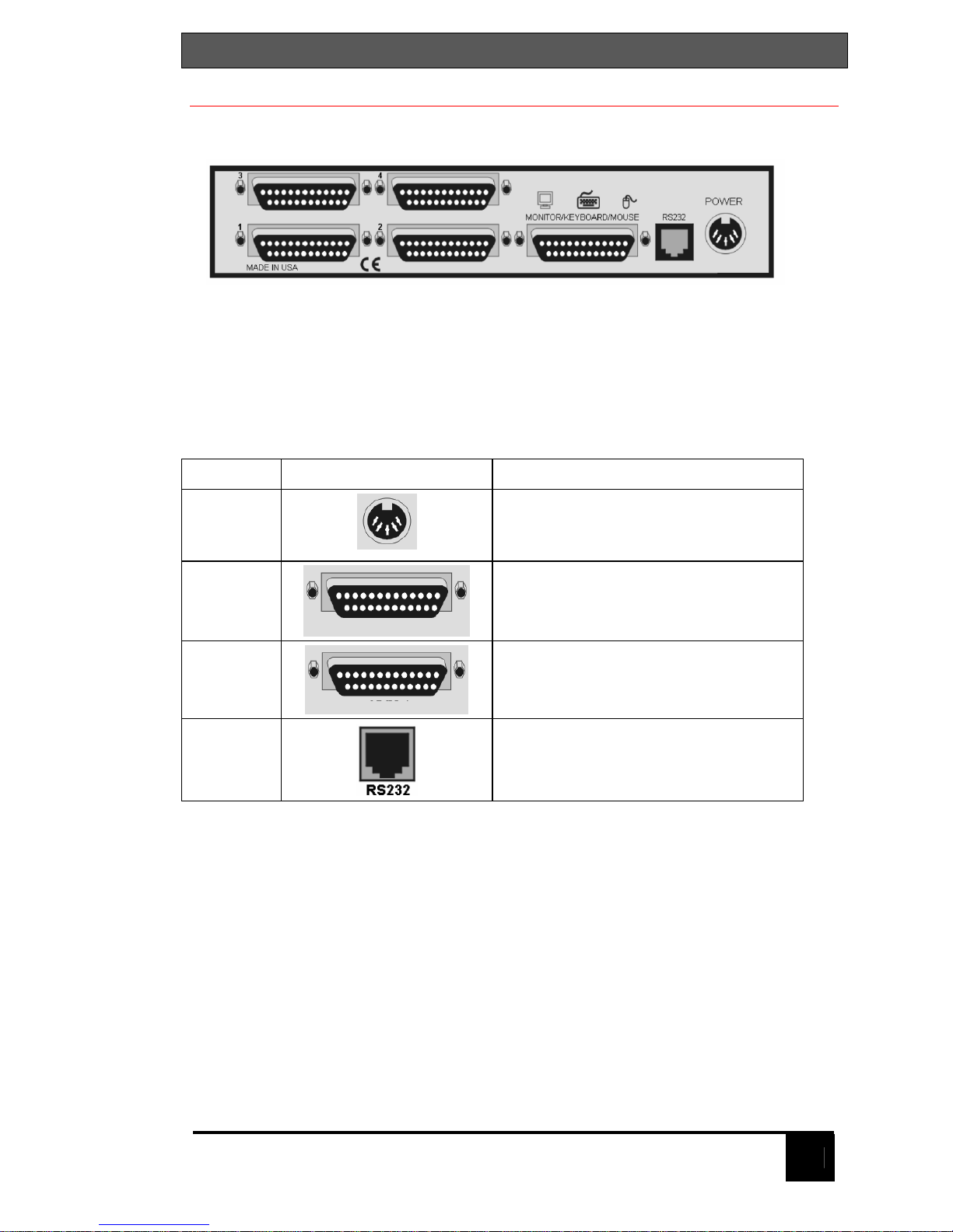
ServSwitch model (rear)
Figure 2. Rear panel
Label Connector Description
Power
“M” Chassis only
DIN 5F
Power adapter connector
1, 2, 3, 4
DB25F
CPU adapter cable connectors
KVM-1
DB25F
KVM cable connector.
RS232
RJ12
6-conductor jack
Table 2. Rear panel connectors
Page 13

SERVSWITCH™
12
Cables
(See Appendix B and B1 for cable part numbers)
ServSwitch to KVM station cables
The KVM cable connects a keyboard, video monitor, and mouse to the
ServSwitch. The KVM cable is configured with a DB25M connector on one end
and a connector for the keyboard, video, and mouse cables on the other end.
These KVM cable connectors should be compatible with the types of connectors
that are on your KVM stations keyboard, monitor, and mouse cables.
ServSwitch to CPU cables
A CPU cable is used to connect each computer to the ServSwitch. The CPU
cable connects from the DB25F CPU ports on the ServSwitch to the keyboard,
video, and mouse ports on each CPU. This cable is configured with a DB25M
connector on one end and a connector for the keyboard, video, and mouse on
the other end. These CPU cable connectors should be compatible with each
CPUs keyboard, video, and mouse port.
ServSwitch Master to Slave unit cables
In systems needing access to additional CPUs, the ServSwitch can be
cascaded to other ServSwitch units. To cascade a ServSwitch to other “Slave”
units, you will need one DB25M to DB25M, switch-to-switch cable for each
expansion unit.
Page 14

KEYBOARD COMMANDS
13
Table 3 shows a list of the keyboard commands that are available. To issue a
keyboard command, first press and release the left control [Ctrl] key, then, within
2 seconds, issue the command. <Ctrl> in the key sequence column is a press
and release of the left control key.
Command Key sequence Description
Select
computer
<Ctrl> nnn where nnn =
computer number
Connects the KVM station to
the selected computer
Next computer <Ctrl> + Selects next sequential CPU
Previous
computer
<Ctrl> - Selects previous sequential
CPU
Scan ON <Ctrl> S Turns scan mode on
Scan OFF <Ctrl> X Turns scan mode off
Scan rate <Ctrl> Tnnn
where nnn=1 – 999
Sets pause time, in seconds,
before switching to next CPU
port in scan mode
Set mode <Ctrl> Mnn <Enter>
where nn = mode value
from Table 4
Alternate way to configure
keyboard and mouse
Null mouse
command
<Ctrl> N Used to re-sync a PS/2 mouse
Reset mouse <Ctrl> O (alpha O) Resets computer’s mouse
(Win NT / 2000 only)
Reset
command
<Ctrl> R Resets and enables mouse
and keyboard on currently
selected computer
Max computers <Ctrl> Pnnn Total ports used (all units)
Units <Ctrl> Unn Number of Slave units
Width <Ctrl> Wnn Number of ports on Slave units
Set typematic
rate value
<Ctrl> Ann <Enter>
where nn=value from
Table 5
Sets keyboard typematic rate
and delay. Default = 20
Identify Rom
Rev
<Ctrl> I Identify Rom revision-Issue
from command prompt or editor
Screen
blanking
<Ctrl> Vnnn <Enter>
where nnn=0-999
Blanks screen after no
keyboard or mouse activity
0-disables blanking
MAC Opt swap <Ctrl> B <Enter> Swaps Mac Opt and Alt keys
Keep <Ctrl> K Saves to flash memory
Table 3. Keyboard commands
Page 15

SERVSWITCH™
14
Table 4 shows the available mode values for the keyboards and mice that are
supported. To change the default keyboard or mouse types from a PC mode 2
keyboard and PS/2 mouse, first connect to the CPU port that the computer
keyboard or mouse needs changing, ([Ctrl],CPU port #,[Enter]) then issue the
mode command [Ctrl],Mnn,[Enter], where nn is the mode value from Table 4.
Mode value Description
1 CPU keyboard = PC mode 1 (Some IBMs & PS/1’s)
2 CPU keyboard = PC mode 2 (Most PCs)
3 CPU keyboard = PC mode 3 most (RISC) Unix w/stations
4 CPU keyboard/mouse = Apple ADB
5 CPU keyboard/mouse = Sun
6 CPU mouse = PS/2 mouse – any brand
7 CPU mouse = 2-button serial (Microsoft - 7 bit)
8 CPU mouse (Reserved for future use)
9 CPU mouse/= 3- button serial (Mouse systems)
10 CPU mouse = PS/2 wheel
11 CPU Keyboard/mouse = USB-PC/MAC
12 CPU Keyboard/mouse = USB-Sun
20 Keyboard = PC – 101/102- PC
21 Keyboard = PC – 104/105-PC Win95
30 Mouse = PS/2 or PS/2 wheel
31 Mouse= Serial 2-button (7 bit-Microsoft)
32 Mouse = Serial 3-button (8-bit – not used)
33 Mouse = Serial 3-button (Mouse systems)
40 Keyboard & mouse - Set all ports to Apple ADB
50 Keyboard & mouse - Set all ports to Sun
60 Keyboard & mouse - Set all ports to PC2 kbd/PS/2 mouse
Table 4. Mode commands
Rate
Keys/
Sec.
Rate
Value
Rate
Keys/
Sec.
Rate
Value
Rate
Keys/
Sec.
Rate
Value
Rate
Keys/
Sec
Rate
Value
30.0 31 15.0 23 7.5 15 3.7 7
26.7 30 13.3 22 6.7 14 3.3 6
24.0 29 12.0 21 6.0 13 3.0 5
21.8 28 10.9 20 5.5 12 2.7 4
20.0 27 10.0 19 5.0 11 2.5 3
18.5 26 9.2 18 4.6 10 2.3 2
17.1 25 8.6 17 4.3 9 2.1 1
16.0 24 8.0 16 4.0 8 2.0 0
Table 5. Typematic value
Page 16

KEYBOARD COMMANDS
15
Keyboard command usage
When using keyboard commands to enter information to the ServSwitch, please
observe the following guidelines to avoid entering incorrect values or no values.
1. All commands start with a press and release of the left control key.
2. Commands following the press and release of the left control key must be
entered within 2 seconds or the command is aborted and the additional
keystrokes will be sent to the selected computer and not the ServSwitch.
3. Use only the numeric keys above the keyboard and not the numeric keypad.
4. Letter commands such as <Ctrl> M are not case sensitive and are only
shown in uppercase for clarity. Do not use the shift key to enter letter
commands.
5. To connect to the previous or next computer, the keyboard command is
<Ctrl> - or <Ctrl> +. The plus and minus keys on the keypad will connect to
the next or previous computer. The - and + keys on the keyboard, next to
the backspace key vary from country to country as to their usage. These
keys can still be used to connect to the next or previous computer.
Page 17

SERVSWITCH™
16
Organizing the system
It is recommended that before any ServSwitch configuration or cable
connections be made, plan how the system will be laid out, the placement of the
CPUs and the placement of the ServSwitch. Take into consideration the cable
lengths needed to connect to the KVM station and each CPU. Identify which
computer will be connected to each CPU connector and if that computer uses a
PC mode 2 keyboard and PS/2 mouse. If not, the CPU port should be preconfigured to change the default keyboard and mouse types to the correct
settings.
If you are adding Slave units to expand your system, it is important that you
understand the width command, especially if your system consists of different
models (4-CPU ports, 8-CPU ports, and 16-CPU ports). For example, if your
system consists of an 8-port master, two 8-port Slave units and one 4-port Slave
unit, and you program the expansion width to 8, there will be 4 blind ports on the
4-port unit. In other words, the 4-port unit will appear to the system as having 8
CPU ports. CPU ports 5-8 are blind ports. If you program the expansion width
to 4, then only CPU ports 1-4 on the 8-port Slave units can be accessed. In
systems that have a mixture of models, it is recommended that the width value
be set to the number of CPU ports on the Slave unit with the most CPU ports.
Installation – Single unit
This section explains how to connect and initially configure the ServSwitch. If
you are cascading two or more ServSwitch units together, please refer to the
Cascade installation section.
Connecting the KVM station
Connect the KVM station’s keyboard, video monitor, and mouse cables to the
corresponding connectors on a KVM cable as shown in Figure 3. The KVM
cable should have the correct connector types for the equipment used. Connect
the DB25M connector into the connector labeled “Monitor/Keyboard/Mouse”.
Apply power
Connect the power transformer to a 110/220-volt source and to the DIN 5F
power adapter connector on the rear panel. Press the ON/OFF button in the
front panel once to turn on the unit.
The green POWER LED will turn on and the power-on diagnostic will run. Wait
until the SELECT 1 LED on the front panel lights before entering any
configuration or switching commands. This assures that the internal diagnostics
have completed. If, for any reason, you need to cycle power on a unit, turn the
power off and wait 10 seconds before re-applying power.
On initial power-up, computer 1 is automatically connected. The SELECT 1
LED on the front panel will light indicating that the KVM station is connected to
the CPU-1 port.
Page 18

INSTALLATION
17
Connecting the computers
Each computer that is connected to the ServSwitch is connected using a CPU
cable. This cable connects from the DB25M CPU port on the rear panel to the
keyboard, monitor, and mouse ports on a CPU (See Figure 3). The keyboard,
monitor, and mouse connectors on the CPU cable should be compatible with the
corresponding ports on the computer being connected. For ease of installation
and configuration, it is recommended that the computers’ power be off at this
time. When a computer is booted, the ServSwitch can automatically determine
the keyboard and mouse types of the connected CPUs.
If removing power to a computer is not feasible, the ServSwitch should be preconfigured, if needed, before the CPU is connected. The default keyboard and
mouse types set for each CPU port is a PC mode 2 keyboard and a PS/2
mouse. If the computer being connected does not use a PC mode 2 type
keyboard and a PS/2 mouse, pre-configure the CPU port for the correct
keyboard and mouse type. Once the CPU port has been configured, the
computer can be connected to the ServSwitch. This procedure should only be
done if the computer’s keyboard and mouse can be disconnected and reconnected with power applied to the computer without affecting the interface.
To pre-configure a CPU port, perform the following:
(Note: the computer should not be connected to the CPU port at this time.)
1. Apply power to the ServSwitch and the KVM station monitor.
2. Switch to the CPU port to pre-configure by pressing and releasing the left
control [Ctrl] key, type in the CPU port number, and press [Enter].
3. Select the correct keyboard type from Table 4.
4. Issue the “Set mode” command. (Ctrl,Mnn,[Enter])
Example : If the keyboard is a PC mode 3 keyboard, the command would
be Ctrl,M3,[Enter]
5. Select the correct mouse type from Table 4.
6. Issue the “Set mode” command (Ctrl,Mnn,[Enter])
Example: if the mouse type is a serial 2 button mouse, the
command would be Ctrl,M7,[Enter]
7. Issue the “Keep” command to save the new values
(Ctrl,K,[Enter])
8. Perform steps 2 through 7 for each CPU port that needs the default
keyboard and mouse changed to a different type.
When all needed CPU ports have been pre-configured, the computers can be
connected. Perform the following for each computer to be connected:
(Refer to the Troubleshooting section if needed and Figure 3 for a example of a
single unit installation)
Steps
1. Turn on the KVM stations monitor and apply power to the ServSwitch.
2. Wait until the “SELECT 1” LED on the front panel lights.
Page 19

SERVSWITCH™
18
3. Switch the ServSwitch to CPU port x. (Ctrl,port #,[Enter])
(Starting with x = 1)
4. Connect the computer that has been pre-determined to be connected to the
CPU port being configured using the appropriate CPU cable.
5. Boot the computer, if needed. You should see the boot-up sequence on the
KVM monitor. If the computer was connected to a pre-configured CPU port
with power applied, you should see that computers video.
6. Switch to the next CPU port to connect a computer to as defined in step 3
and perform steps 4 and 5 for this computer and for then for the remaining
CPU ports.
4 CPUs connect to the ServSwitch
Figure 3. Single Unit installation
If you are using the audio features of the ServSwitch Ultra, connect the audio
cable on the CPU cable to the audio out of the CPU sound card. Connect the
audio cable on the KVM cable to a pair of speakers or headphones.
KVM Station
ServSwitch
CPU cable KVM cable
Page 20

INSTALLATION
19
Installation – Cascading units
The ServSwitch units can be cascaded together to expand the number of
computers that can be accessed from the KVM station.
When cascading units, one unit becomes the “Master” unit and all others are
“Slave” units. Each computer port on the master unit can be connected to a
Slave units’ KVM connector. Figure 4 illustrates the addition of four 4-port Slave
units.
The ServSwitch “Master” must be configured to properly manage the cascaded
units. The maximum number of computers, the number of Slave units
connected, and the number of ports (width) on the Slave units must be entered
and saved. In the example in Figure 4, the maximum computer entry would be
16, the number of Slave units is 4, and the number of ports, or width, on each
Slave unit would be 4. It is recommended that all Slave units have the same
number of computer ports.
The “Maximum computers” value is figured as follows:
If all Units in the system have the same number of CPU ports, (no mixed
models) then you can count the CPU ports used to connect to the computers.
The ports on the master unit used for expansion should not be counted.
In the example in Figure 4, the width value is 4, the number of Slave units is 4,
and the CPU ports on the master unit that are not used for expansion is 0. The
Maximum computers value would be 4 x 4 + 0 or 16.
To configure the “Maximum computer”, “Units”, and “Width” values, connect a
KVM station to the Master unit. Power on the KVM monitor and the Master unit.
Wait until the SELECT 1 LED lights.
To enter the “Maximum computer” value, press and release the left control [Ctrl]
key,P,nnn,[Enter], nnn=Maximum computers value.
The “Units” value is the total number of Slave units in the system. To enter the
“Units” value press and release the left control [Ctrl] key,U,nn,[Enter],
nn=number of Slave units. Valid entries are 1-16.
The “Width” value is the number of CPU ports on a single Slave unit. To enter
the “Width” value press and release the left control [Ctrl] key,W,nn,[Enter],
nn=number of ports on an Slave unit.
Refer to “Organizing the system” for further information.
Save changes by pressing and releasing the left control [Ctrl] key, K, [Enter]
Page 21

SERVSWITCH™
20
Connecting “Slave” units
To properly install the Slave units, follow the below steps.
Step: (Refer to Figure 4)
1. Connect the KVM stations keyboard, monitor, and mouse to the master units
KVM connector using the appropriate KVM cable.
2. Connect CPU port #1 on the master unit to the KVM connector on Slave unit
#1 using a DB25 to DB25 expansion cable.
3. Connect the next sequential CPU port on the master unit to the KVM
connector on the next sequential Slave unit.
4. Connect the remaining Slave units to the master unit.
Connecting the computers
When all “Slave” units have been connected, the computers can be connected.
The following installation steps use the example in Figure 4.
It is recommended that the computers being connected be powered off. If
removing power is not feasible, perform the pre-configuration procedure, if
needed, before connecting a computer with power applied.
Steps:
1. Apply power to all ServSwitch units and the KVM monitor.
2. Switch to the CPU port the computer is being connected to by pressing and
releasing the left control [Ctrl] key, type in the CPU port number (starting
with port #1), and press [Enter].
3. Connect the computer to the CPU port using the appropriate CPU cable. If
the computer being connected does not use a PC mode 2 keyboard and a
PS/2 mouse, or is being connected with power applied, pre-configure the
CPU port, if needed, before connecting the computer. Change the default
keyboard and mouse from a PC mode 2 keyboard and a PS/2 mouse to the
correct ones the computer uses. If the computer being connected uses a
PC mode 2 keyboard and a PS/2 mouse, skip the pre-configuration
procedure and connect the computer to the assigned CPU port.
NOTE: Connecting a computer’s keyboard and mouse to the ServSwitch with
power applied to the computer should only be done if the keyboard and mouse
can be disconnected and re-connected without affecting the interface.
Pre-configuration procedure
Issue the mode command to change the keyboard and issue the command
again to change the mouse type or issue a global mode command to change all.
Make sure the ServSwitch is connected to the correct CPU port before entering
the mode command.
a. Select the correct keyboard type, if needed, from Table 4.
b. Issue the “Set mode” command. (Ctrl,Mnn,[Enter])
Example : If the keyboard is a PC mode 3 keyboard, the command
would be Ctrl,M3,[Enter]
c. Select the correct mouse type, if needed, from Table 4.
Page 22

INSTALLATION
21
d. Issue the “Set mode” command (Ctrl,Mnn,[Enter])
Example: if the mouse type is a serial 2 button mouse, the
command would be Ctrl,M31,[Enter]
e. Issue the “Keep” command to save the new values
(Ctrl,K,[Enter])
f. Perform steps a through e for each CPU port that needs the
default keyboard and mouse changed to a different type.
4. Boot the computer if power was not applied. You should see the boot-up
sequence on the KVM monitor. If the computer was connected with power
applied, you should see that computer’s video.
5. Verify that the keyboard, video, and mouse function properly before
proceeding.
6. Switch to the next sequential CPU port as explained in step 2 and perform
steps 3-5 for this computer and for the remaining computers.
Figure 4. Cascading units
CPUs 1-4 CPUs 5-8
CPUs 9-12 CPUs 13-16
Page 23

SERVSWITCH™
22
Selecting a computer
To connect to a computer, you can select it from the ServSwitch front panel,
select it by keyboard commands, or select it through the RS232 serial port.
Selecting a computer from the front panel
Using the - and + buttons on the front panel will switch to the previous (-)
computer port or advance (+) to the next computer.
Selecting a computer using keyboard commands
Press and release the left control <Ctrl> key, then enter the computer port
number. Pressing and releasing the left control <Ctrl> key then the + or - key
will advance forward or backwards one sequential port.
Selecting a computer through the RS232 port
For your convenience, a computer or terminal can be connected to the RS232
serial port on the unit's rear panel. This allows you to send switching commands
from your computer's serial port or to load new flash firmware. You will need
serial cabling with 4-pin or 6-pin RJ jacks, and the appropriate adapter (either
DB-25 female to RJ11/12 female or DB-9 female to RJ11/12 female, depending
upon your equipment). This adapter may have been supplied with your package.
1. Insert the RJ cable between the RS232 serial port on UltraView Pro's rear
panel, and the RJ female connector of the appropriate adapter.
2. Connect the adapter to one of the computer's (or terminal's) COM ports.
3. Set your computer at 9600 baud, no parity, 8 bits, 1 stop-bit.
4. To switch ports, enter the 1-3 digit port number followed by enter: xxx
<Enter>.
Reset to factory defaults
To reset the ServSwitch to the original factory default settings, first, power down
the unit, press and hold the – (minus) switch in and turn the unit’s power on.
Keep the – (minus) switch held in until the unit switches to the last port on the
unit (port 4, 8, or 16). If you release the – (minus) switch before the last port is
switched to, the defaults will not be restored.
Rack mounting
The ServSwitch can be rack mounted using a Rackmount kit. See Appendix D
and E for instructions and Appendix B for part numbers.
Page 24

SERIAL PORT
23
Serial Port (RS232)
The RS232 serial port on the ServSwitch rear panel can also be used for
sending switching commands from a stand-alone computer or terminal or to load
flash firmware upgrades to the unit. A serial cable and an RJ to DB9 adapter
are included with the unit. Perform steps 1-3 below to use the serial port.
1. Connect the serial cable to the RS232 serial port on the rear panel of the
ServSwitch and to the RJ12 connector on the adapter.
2. Connect the DB9 connector on the adapter to the stand-alone computer or
terminals DB9 COM port.
3. Set the computers communication program for:
a. 9600 baud
b. no parity
c. 8 bits
d. 1 stop-bit
Firmware update
The ServSwitch’s flash memory can be updated with the latest firmware using
the RS232 serial port. Updates can be obtained from Black Box. Verify the
unit’s program and kernel versions against the current versions on our web site.
To verify the program version, start a text editor application like notepad, press
and release the left control (Ctrl) key, then press the “I” key and the program
version will display.
To update the firmware, first obtain the latest revision from Black Box and save
it to a stand-alone computer that is not connected to the ServSwitch. Connect
the serial cable from the ServSwitch to the serial port of the stand-alone
computer as described in steps 1-3. There are two methods of loading the
downloaded programs to flash memory.
Method 1 – Using a communication program
1. Press both the - and + switches on the front panel and power on the
ServSwitch. LED 1 will light indicating the unit is ready to accept the
upgrade file at 9600 baud. To use 57600 baud rate, press the + switch and
LED 1 will turn off and LED 4 will light.
2. Run your communication program. Set the baud rate to the correct rate and
put the program in direct connect mode. When the - or + switch is pressed,
you should see the message:
”Waiting for file at 9600 or 57600 baud.”
3. Send the file to the unit using a simple ASCII text file protocol. While the
file is being sent, periods are sent to indicate the file copy progress. Once
the file has been sent, you should see the following message:
”Receive successful”
”Hit space to program”
4. Hit the space bar to start programming the flash memory. The
programming and verifying progress is indicated by sending periods. You
Page 25

SERVSWITCH™
24
should see the following message:
”Programming flash”
…………………
”Verifying flash”
…………………
”Verify successful”
”Hit enter to boot”
5. Hit enter and the ServSwitch will re-start with the new firmware.
6. Hit the enter key to continue. The ServSwitch is now operational with the
new firmware update.
If the upgrade is not successful, you will see one of the following error
messages:
¾ Checksum error or Record error or Data error
¾ Receive failed
Try again Y/N?
If any of these errors occur, check the RS232 cable, the connectors, and the
adapter. Make sure they are in good working order. Verify the communication
program is configured correctly. Enter “Y” to try upgrading the flash again. If
programming is unsuccessful, the unit should be serviced.
Method 2 – Using the front panel switches with a file copy.
1. Press both the - and + switches on the front panel and power up the
ServSwitch. The ServSwitch is ready to accept the upgrade file. LED 1 will
light indicating the unit is set at 9600 baud. To use 57600 baud, press the
+ switch, LED 4 will light. Copy the file to the unit. While the file is being
copied, LED 1 or 4 will flash. Once the file is copied, LED 2 will light.
2. Press and release the + switch, LED 2 flashes off for a brief instant. The
flash is now being programmed and verified. LED 3 now lights.
3. Press and release the + switch, LED 3 flashes off for a brief instant. LED 4
now lights.
4. Press and release the + switch. LED 1 now lights. The box is now
operational and port 1 is selected. The flash loading procedure is complete.
Page 26

TROUBLESHOOTING
25
TROUBLESHOOTING
Computer does not boot, keyboard or mouse error received.
¾ Cable is loose, reseat cable and on PC hit F1 to continue or reboot
computer.
¾ Wrong cable or keyboard and mouse cables reversed.
¾ Cable is defective; try using cable from another computer.
¾ Port on the ServSwitch is defective; try using another port on ServSwitch. If
the problem goes away port is defective.
¾ Port on computer is defective, try plugging in keyboard or mouse directly if
problem remains computer port is defective. If power status LED not lit, fuse
on motherboard may be blown.
¾ Computer keyboard and mouse not configured.
Mouse driver does not load.
¾ If PS/2 type mouse, computer must be connected to ServSwitch at boot-up
time in order for the mouse to be recognized by the computer. Reboot
computer with ServSwitch powered on and cable attached.
¾ Computer keyboard and mouse not configured.
Can’t switch computers from keyboard
¾ Power to the ServSwitch was removed for less than three seconds possibly
causing keyboard to lock up. Disconnect and re-connect the keyboard.
¾ If PS/2 type keyboard and mouse, cables may be reversed.
¾ Not using left control key. Using numeric keypad instead of keys on top row.
Not releasing control key before typing in number. Waiting more than 2
seconds to enter computer number. Using caps lock or shift key.
Wrong or missing characters from those typed
¾ For PCs, the mode of the keyboard does not match that of the computer.
Issue the mode command, usually 1 for IBM PS/2s, 3 for Unix computers,
and 2 for all others. The default setting is mode 2. Sometimes an incorrect
mode will confuse the computer or keyboard and require re-booting the
computer or resetting the keyboard by unplugging and plugging it back in.
Switch to Switch failure
n Verify the firmware in all like switches is the same revision.
Mouse does not move
¾ Mouse not configured.
¾ ServSwitch turned off after or not connected when computer
booted or application using mouse run. Exit and re-enter application using
mouse or issue reset command.
¾ PS/2 mouse was not connected when ServSwitch powered up or
disconnected and reconnected. Issue the reset command or reconfigure the
mouse.
Page 27

SERVSWITCH™
26
PS/2 mouse gets out of sync
¾ Cabling was disturbed during mouse movement. Issue the null command
once or twice to re-sync the mouse. Update mouse driver. Try using ctrl O
command to recover if O/S is NT.
¾ Sun keyboard needs to be reset, with unit power on, disconnect and re-
connect the sun keyboard.
Video fuzzy
¾ Cable too long or wrong type. Verify that resolution and distance match.
See Appendix G. Upgrade cable if necessary.
Video not synchronized or wrong color
¾ Cable is loose, reseat cable.
¾ Monitor not capable of syncing to video selected, upgrade monitor.
¾ Cable is defective; try using cable from another computer if problem goes
away cable is defective.
¾ Port on ServSwitch is defective; try using another port on ServSwitch. If
problem goes away port is defective.
Lower resolution OK, but can’t enter high resolution mode
¾ Video driver has not been setup for this resolution. Configure the driver.
Slave unit does not switch
¾ Maximum ports command not issued.
¾ Width or units command not configured properly. Reconfigure them to
match number of computers and how they are connected.
Page 28

SAFETY
27
Safety
This ServSwitch KVM switch has been tested for conformance to safety
regulations and requirements, and has been certified for international use. Like
all electronic equipment, the ServSwitch should be used with care. To protect
yourself from possible injury and to minimize the risk of damage to this Unit,
read and follow these safety instructions.
n Follow all instructions and warnings marked on this Unit.
n Except where explained in this manual, do not attempt to service this Unit
yourself.
n Do not use this Unit near water.
n Assure that the placement of this Unit is on a stable surface or rack
mounted.
n Provide proper ventilation and air circulation.
n Keep power cord and connection cables clear of obstructions that might
cause damage to them.
n Use only power cords, power transformer and connection cables designed
for this Unit.
n Use only a grounded (three-wire) electrical outlet.
n Keep objects that might damage this Unit and liquids that may spill, clear
from this Unit. Liquids and foreign objects might come in contact with
voltage points that could create a risk of fire or electrical shock.
n Operate this unit only when the cover is in place.
n Do not use liquid or aerosol cleaners to clean this Unit. Always unplug this
Unit from its electrical outlet before cleaning.
n Unplug this Unit from the electrical outlet and refer servicing to a qualified
service center if any of the following conditions occur:
§ The power cord or connection cables is damaged or frayed.
§ The Unit has been exposed to any liquids.
§ The Unit does not operate normally when all operating
instructions have been followed.
§ The Unit has been dropped or the case has been damaged.
§ The Unit exhibits a distinct change in performance, indicating a
need for service.
Page 29

SERVSWITCH™
28
Safety and EMC Regulatory Statements
Safety Information
Documentation reference symbol. If the product is marked
with this symbol, refer to the product documentation to get
more information about the product.
WARNING A WARNING in the manual denotes a
hazard that can cause injury or death.
CAUTION A CAUTION in the manual denotes a hazard that
can damage equipment.
Do not proceed beyond a WARNING or CAUTION notice until you have
understood the hazardous conditions and have taken appropriate steps.
Grounding
These are Safety Class I products and have protective earthing terminals. There
must be an un-interruptible safety earth ground from the main power source to
the product’s input wiring terminals, power cord, or supplied power cord set.
Whenever it is likely that the protection has been impaired, disconnect the
power cord until the ground has been restored.
Servicing
There are no user-serviceable parts inside these products. Only service-trained
personnel must perform any servicing, maintenance, or repair.
Only items mentioned in this manual may be adjusted by the user.
Page 30

SAFETY
29
Informations concernant la sécurité
Symbole de référence à la documentation. Si le produit est
marqué de ce symbole, reportez-vous à la documentation du
produit afin d’obtenir des informations plus détaillées.
WARNING Dans la documentation, un WARNING indique un danger
susceptible
d’entraîner des dommages corporels ou la mort.
CAUTION Un texte de mise en garde intitulé indique un danger suscep-
tible de causer des dommages à ‘équipement.
Ne continuez pas au-delà d’une rubrique WARNING ou CAUTION avant d’avoir
bien compris les conditions présentant un danger et pris les mesures
appropriées.
`Cet appareil est un produit de classe I et possède une borne de mise à la terre.
La source d’alimentation principale doit être munie d’une prise de terre de
sécurité installée aux bornes du câblage d’entrée, sur le cordon d’alimentation
ou le cordon de raccordementfourni avec le produit. Lorsque cette protection
semble avoir été endommagée, débrancher le cordon d’alimentation jusqu’à ce
que la mise à la terre ait été réparée.
Aucune pièce contenue à l’intérieur de ce produit ne peut être réparée par
l’utilisateur.
Tout dépannage, réglage, entretien ou réparation devra être confié
exclusivement à unpersonnel qualifié.
Page 31

SERVSWITCH™
30
Appendix A. Initial factory settings
Setting Default value
KVM keyboard/mouse type PC mode 2 – PS/2
CPU keyboard/mouse type PC mode 2 – PS/2
Scan time interval 5 seconds
Power on scan Off
Maximum ports Same as physical number of ports
Expansion width 16
Slave units 0
Caps/Numlock/Scroll Numlock On
Page 32

APPENDICES
31
Appendix B. Parts and cables
Note: + Audio = 2-3.5mm stereo audio jacks
* Cable lengths in 1, 5, 10, 20 /(Hi Res.) 35, 50, 75, 100 feet
** Cable lengths in 5, 10, 20, /(Hi Res.) 35, 50, 75, 100 feet
Part number Description (Multi-Platform models)
EHN225-nnnn* Coax VGA-Sun Kbd-Sun mouse
EHN540-nnnn* Coax Apple video-Kbd-mouse to DB25M
EHN515-nnnn* SUN w/ VGA (HD15) Video, SUN Kbd & mouse
EHN560-nnnn* Coax Apple video-Kbd-mouse to DB25M
EHN215-nnnn* Apple CPU video-Kbd-mouse to DB25M
EHN206-nnnn* Coax Sun CPU video-Kbd-mouse to DB25M
EHN500-nnnn* SGI-KVM 13W3 / PS2
EHN501-nnnn* SGI-CPU 13W3 / PS2
EHN520-nnnn* RS6000 CPU 13W3 / PS2
EHN521-nnnn* RS6000 KVM 13W3 / PS2
Part number Description (PC Models)
EHN151-nnnn** CPU – DB25M to HD15F / PS2 Kbd / PS2 mouse
EHN151A-nnnn** CPU - DB25M to HD15F / PS2 Kbd / PS2 mouse + Audio
EHN154A-nnnn* KVM - DB25M to HD15F / PS2 Kbd / PS2 mouse + Audio
EHN270-nnnn* KVM - DB25M to HD15F / DIN5 / DB9 - Coax (AT-style)
EHN052-nnnn* KVM - DB25M to HD15F / DIN5 / DB9 (AT-style)
EHN283-nnnn* KVM - DB25M to HD15F/ PS2 Kbd / PS2 mouse - Coax
EHN282-nnnn** CPU - DB25M to HD15F / DIN5 / DB9 – Coax (AT style)
EHN485-nnnn** CPU - DB25M to HD15F / USB Type A
EHN485A-nnnn** CPU - DB25M to HD15F / USB Type A + Audio
EHN382-nnnn** CPU - DB25M to HD15F / PS2 Kbd / PS2 mouse
EHN382A-nnnn** CPU - DB25M to HD15F / PS2 Kbd / PS2 mouse + Audio
EHN383-nnnn* KVM - DB25M to HD15F / PS2 Kbd / PS2 mouse
EHN383A-nnnn* KVM - DB25M to HD15F / PS2 Kbd / PS2 mouse + Audio
EHN154-nnnn* KVM - DB25M to HD15F / PS2 Kbd / PS2 mouse
EHN154A-nnnn* KVM - DB25M to HD15F / PS2 Kbd / PS2 mouse + Audio
EHN284-nnnn* Cascading Cable DB25M to DB25M
PS024 110/220 VAC - Power transformer
RMKxxM Rackmount Kit (xx = 19, 23, or 24 in.)
Page 33

SERVSWITCH™
32
Appendix C. General Specifications
The ServSwitch part numbers are: KV3104MN-R4 (PC/Unix)
KV5004MN-R2 (Multi-Platform)
Dimensions 8.8 x 4.85 x 1.75 in
22.3 x 12.3 x 4.4 cm
Weight 4lb / 1.8kg
Environment 0 – 55° C / 32 – 131° F, 5%-80% non-cond. RH
Power Auto-switching 90 – 240 VAC, 60 watts
Connectors Power – IEC 320 standard receptacle
CPU/KVM connector – DB25F
RS232 connector – RJ12, 6 conductor
Video bandwidth 250 Mhz
Video sync HV, composite, and sync-on-green
Chassis Electro galvanized steel, black powder coated
Controls Power switch, - / + switch
Indicators 1 Power LED
4 Select LEDs
4 Computer power LEDs
Approvals Mini chassis TUV, CE, VCCI-A, CB
Page 34

APPENDICES
33
Appendix D. Rack mount instructions
The ServSwitch can be mounted in a rack using the Rackmount kits.
The optional rack mount kit includes the following items:
¾ Two black anodized mounting brackets.
¾ Four 6-32 x 3/8” flat head mounting screws.
To rack mount your ServSwitch, attach the two rack mounting brackets to your
unit with the short flange against the unit using the four screws provided.
Secure the mounting brackets to the rack using the appropriate size bolts, nuts
and lock washers. Using hardware other than that provided could cause
damage to the electronics and/or result in loss of mounting integrity. Do not
over tighten the screws used to mount the unit to the mounting brackets.
The following general guidelines should be observed when installing your unit
into a rack.
1. The ServSwitch is designed to work in an ambient temperature of 0
ο
C to
45
ο
C (32
ο
F – 113ο F).
2. Do not block power supply vents or otherwise restrict airflow when rackmounting this unit.
3. Mechanical loading of the rack should be considered to prevent instability
and possible tipping over.
4. Tighten all connectors securely and provide adequate strain relief for all
cables.
5. Provide a grounded power source to all units. Pay special attention to
overall branch circuit load ratings before connecting equipment to this
source. Overloaded circuits are potential fire hazards and can cause
equipment failures or poor performance.
Appendix E. Rack mount illustration
Page 35

SERVSWITCH™
34
Appendix F. Keyboard mapping
KEYBOARD MAPPING FROM PC TO APPLE AND SUN
COMPUTERS
PC 101/102
APPLE SUN
Left Control Left Control Left Control
Left Alt Left Cloverleaf Left Diamond
Right Alt/Alt Graph Right Option Alt Graph
Right Control Power Key Power Key
Left Control, then
Pause, then A
Left Control, then
Pause, hen A
Stop + A
PC 104/105
(WIN95)
APPLE SUN
Left Control Left Control Left Control
Left Win95 (Start) Left Cloverleaf Left Diamond
Left Alt Left Option Left Alt
Right Alt/Alt Graph Right Option Alt Graph
Right Win95 (Start) Right Cloverleaf Right Diamond
Right Win95 (App) Power Key Power Key Right
Right Control Right Control Compose
Left Control, then
Pause, then A
Left Control, then
Pause, then A
Stop + A
Pause or Keypad / Stop
Keypad * Again
Keypad 8 Props
Keypad 9 Undo
Keypad 5 Front
Keypad 6 Copy
Keypad 2 Open
Keypad 3 Paste
Keypad 0 Find
Keypad. Cut
Home Help
End Mute
Page Up Volume Up
Page Down Volume Down
Delete Power
Page 36

APPENDICES
35
Appendix G. Video distance capability
The table below shows the distances, resolution, and quality of video that can
be expected with normal or coax cabling. This table applies to the MASTER unit
only. There will be some degradation when units are chained together.
Resolution Video distance capability
@ 75Hz 5’ 10’ 20’ 35’ 50’ 75’ 100’
640x480
C4 Z4
C4
Z4
C4
Z3
C4 C4 C4 C4
800X600
Z4
C4
Z4
C4
Z4
C4
Z3
C4 C4 C4 C4
1024x768
Z4
C4
Z4
C4
Z4
C4
Z3
C4 C4 C4 C3
1280x1024
Z4
C4
Z3
C4
Z3
C4
Z3
C3 C3 C3 C2
1600x1200
Z3
C4
Z3
C3
Z2
C3 C3
C3 C2 C2
Legend
Z – Normal cabling
C – Coax cabling
4- Perfect or near-perfect video; Unable to
easily detect defects.
3- Very acceptable; Images clear, small reflections
around colored letters
2- Acceptable: Slightly fuzzy images, readable
text, acceptable usage for short periods of time,
can cause eye fatigue.
1- Unusable; images smeared, text not easily
readable.
Page 37

NOTES
 Loading...