

Page 1

JANUARY 2006
KV21008A
KV22008A
KV22016A
KV21008E
KV22008E
KV22016E
Page 2

Page 3

SERVSELECT
TM
III INSTALLER/USER GUIDE
Welcome to the ServSwitch™ Family!
Thank you fo r purc hasi ng a B LAC K BOX® ServSelect™ III! We appreciate your business,
and we think you’ll appreciate th e ma ny ways tha t yo ur n ew ServSelect III will save you
money, time, and effort.
That’s because the ServSwitch family is all about breaking awa y from the trad ition al,
expensive model of computer management. Yo u kn ow, th e one -size-fits-all-even-if-itdoesn’t model tha t sa ys , “ O ne co mp ute r ge ts o ne use r sta tion , no more, no less.” Why not a
single user station (monitor, keyb oard, and mouse) for mu ltiple computers—even comp uters
of different platforms? Why not a pair of user stations, e ach of wh ich can control m ultiple
computers? Why not multiple user stations for the same computer?
With our Ser vSwitch products , th ere’s no reason why n ot. We carry a broad line of r ob u st
solutions for all these applications. Do you have just two PCs, and need an economical
alternative to keeping two mon itors, keyb oard s, and mic e on your de sk? Or do you nee d to
share dozens of c omputers, including a mix of IBM® PC, RS/6000®, Apple®
Macintosh®, Sun Microsystem s ® , and SGI™ compatibles among mult iple users with
different access levels? Do es your switch have to sit solidly on a work table and use
regular everyday cabl es? Or does it have to be mounted in an equipment rack and use
convenient many-to-one cables? No matter how large or small your setup is, no matter
how simple or how complex, we’re confident we have a ServSwitch system that’s just
right for you.
The ServSwitch
switching needs!
™ family from BLACK BOX—the one-stop answer for all your KVM
*
This manual will tell you all about your new ServSelect III, including how to install,
operate, and troubleshoot it. For an introduction to the ServSelect III, see Chapter 2. The
ServSelect III product codes covered in this manual are:
KV21008A KV21008E
KV22008A KV22008E
KV22016A KV22016E
This manual also includes information about the ServSelct III cables and Server Access
Modules (SAMs), which have their own manuals or installation guid es.
ServSelect III cables SAMs
EHN21000PS2-0007 KV123A
EHN21000PS2-0010 KV125A
EHN21000PS2-0015 KV126A
EHN21000USB-0007 KV127A
EHN21000USB-0010
EHN21000USB-0015
1
Page 4

SERVSELECT
TM
III INSTALLER/USER GUIDE
FEDERAL COMMUNICATIONS COMMISSION
AND INDUSTRY CANADA
RADIO-FREQUENCY INTERFERENCE ST ATEMENTS
This equipment generates, uses, and can radiate radio-frequency energy and if not
installed and used properly, that is, in strict accordance with the manufa ct urer’s
instructions, may cause interference to radio communication. It has been tested and found
to comply with the limits for a Class A computing device in accordance with the
specifications in Subpart B of Part 15 of FCC rules, which are designed to provide
reasonable protection against such interference when the equipment is operated in a
commercial enviro nme nt. Opera tio n of this equi pm e nt in a residential area is likely to
cause interference, in which case the user at his own exp ense will be required to take
whatever measures may be nece ssary to correct the interference.
Changes or modifications not expressly approved by the party responsible for compliance
could void the user’s authority to operate the equipment.
This digital apparatu s does not exceed the Class A lim its for radio noise emission from
digital apparatus set out in the Radio Interference Re gulation of Industry Canada.
Le présent appar eil numérique n’ émet pas de bruit s radioélectriques dépassant les limites
applicables aux appareils numériques de la classe A prescrites dans le Règlement sur le
brouillage radioélectrique publié par Industrie Canada.
EUROPEAN UNION DECLARATION OF CONFORMITY
This equipment has been tested and found to comply with the limits for a Class A
computing device i n accordance with the specifications in the Eu ropean standard
EN55022. These limits are designed to provide reasonable protection against harmful
interference. This equi pment generates, uses and can radiate radio-frequency energy, and
if not installed and used in accordance with the instructions, might cause harmful
interference to radio or television reception.
However, there is no guarantee that harmful interference will not occur in a particular
installation. If this equipment does cause interference to radio or television reception,
which can be determined by turning the equipment on an d off, you can correct the
interference with one or more of the following measures:
a. Reorient or relocate the receiving antenna.
b. Increase the separation bet ween the equipment and the receiver.
c. Connect the equipment to an outlet on a circuit different from that to which the receiver
is connected.
d. Consult the supplier or an experienced radio/TV technician for help.
2
Page 5

COMPLIANCE STATEMENTS
Shielded cables must be used with this equipment to maintain compliance with radio
frequency energy emission regulations and ensure a suitably high level of immunity to
electromagnetic disturbances. This equipment has also been found t o comply with
European stand a rds EN50082 and E N 60950.
Japanese Compliance Statement
Other Agency Approvals
USA (UL, FCC)
Canada (cUL, ICES-003)
European Union (CE)
Germany (GS)
TRADEMARKS USED IN THIS MANUAL
BLACK BOX® and the logo are registered tradema r ks, and ServSwitch, ServSelect, an d
ServSelect IP are trademarks of BLACK BOX Corporat ion.
Apple, Mac, and Macintosh are registered trade marks of Apple Computer, Inc.
IBM, PS/2, and RS/6000 are registered trademarks of Internatio nal Business
Machines Corporation.
Microsoft, HyperTerminal, Windows, Windows NT, and Windows XP are trademarks or
registered trademarks of Microsoft Corporation in the United States and/or other countries.
Sun and Sun Microsystems are registered trademarks of Sun Microsyst ems, Inc. in the
United States and oth er countries.
UL is a registered trademark of Underwriters Laboratories Inc.
Any other trademarks mentioned in this manual are ackno wledged to be the property of
the trademark owners.
3
Page 6

SERVSELECT
TM
III INSTALLER/USER GUIDE
Normas Oficiales Mexicanas (NOM)
Electrical Safety Statement
INSTRUCCIONES DE SEGURIDAD
1. Todas las instrucciones de seguridad y operació n deberán ser leídas antes de que el
aparato eléctrico sea operado.
2. Las instrucciones de seguridad y operación debe rán ser guardadas para
referencia futura.
3. Todas las advertencias en el aparato eléctrico y en sus instrucciones de operación
deben ser res p e tadas.
4. Todas las instrucciones de oper ación y uso deben ser seguidas.
5. El aparato eléctrico no deberá ser usado cerca del agua—por ejemplo, cerca de la tina
de baño, lavab o, só ta n o mo ja do o cerc a de un a a lbe r c a , etc .
6. El aparato eléct rico debe ser us ado únicamente con carritos o pe destales que sean
recomendados por el fabricante.
7. El aparato eléctrico debe ser montado a la pared o al techo sólo como sea
recomendado por el fabrican t e.
8. Servicio—El usuario no debe intentar dar servicio al equipo eléctrico más allá a lo
descrito en las instrucciones de operación. Todo otro servicio deberá ser referido a
personal de servicio calificado.
9. El aparato eléc trico debe ser si tuado de tal manera que su posición no inte rfiera su
uso. La colocación del aparato eléctrico sobre una ca ma, sofá, alfombra o superficie
similar puede bloquea la ventilación, no se debe colocar en libreros o gabinetes que
impidan el fl ujo de aire por los orificios de ventilación .
10. El equipo eléctrico debe r ser situado fuera del alcance de fuentes de calor como
radiadores, r egistros de cal or, estufas u otros aparatos (incluyendo amp li ficadores)
que producen calor.
11. El aparato eléctrico de berá ser co nnectado a u na fuente de poder sólo de l tipo d escrito
en el instructivo de operación, o como se indique en el aparato.
12. Precaución de b e ser tomada de tal manera que la tierra fisica y la pola riza ción del
equipo no sea eliminada.
13. Los cables de la fuente de poder deben ser guiados de tal manera que no sean pisados
ni pellizcados por objetos colocados sobre o contra ellos, poniendo particular
atención a los conta ctos y receptáculos donde salen del aparato.
14. El equipo eléctrico debe ser limpiado únicamente de acuerdo a las recomen daci ones
del fabricante.
15. En caso de existir, una antena extern a deberá ser localizada le jos de las lineas
de energia.
16. El cable de corr iente deberá ser desconectado del cuando el equipo no sea usado por
un largo periodo de tiempo .
17. Cuidado debe ser tomado de tal manera que objectos liquidos no sean derramados
sobre la cubierta u orificios de ventilación.
18. Servicio por per s onal calificado deberá ser provisto cuando:
A: El cable de poder o el contacto ha sido dañado; u
B: Objectos han caído o líquido ha sido derr amado dentro del aparato; o
4
Page 7

NOM STATEMENT
C: El aparato ha sido expuesto a la lluvia; o
D: El aparato parece no operar normalmente o muestra un cambi o en su
desempe ñ o; o
E: El aparato ha sido tirado o su cubierta h a sido dañada.
5
Page 8

SERVSELECT III INSTALLER/USER GUIDE
Table of Conte nts
1. Specifications...................................................................................................7
2. Product Overview.............................................................................................9
2.1 Features and Benefits.....................................................................................................9
2.2 Safety Precautions........................................................................................................11
3. Installation......................................................................................................13
3.1 Getting Started.............................................................................................................13
3.2 Rack Mounting Your ServSelect III Switch................................................................13
3.3 Installing the ServSelect III Switch .............................................................................14
3.4 Connecting Users.........................................................................................................16
3.5 Cascading ServSelect III Switches..............................................................................16
3.6 Adding Legacy Switches.............................................................................................17
3.7 Setting Up Your ServSelect III Switching System......................................................19
4. Basic Operations............................................................................................21
4.1 Controlling Your System at the Analog Ports.............................................................21
4.2 Viewing and Selecting Ports and Servers....................................................................21
4.3 Navigating the OSD Interface......................................................................................23
4.4 Configuring OSD Interface Menus..............................................................................25
4.5 Displaying Version Information..................................................................................34
4.6 Scanning Your System.................................................................................................35
4.7 Running System Diagnostics.......................................................................................37
4.8 Broadcasting to Servers...............................................................................................39
4.9 Changing Your Switch Mode......................................................................................41
5. Advanced Operations....................................................................................43
5.1 Using Administrator Privileges ...................................................................................43
Appendix A: Flash Upgrades............................................................................47
6
Page 9

CHAPTER 1: SPECIFICATIONS
1. Specifications
During the cour se of this product’s lifetime, modifications might be made to its hardw are
or firmware that could cause these specifications to change without notice.
ServSelect III Product Specifications
Agency Approvals
UL, FCC Class A, cUL, ICES Class A, CE, GS,
VCCI Class A
Mechanical
Height x Width x Depth:
Weight: 8 lbs (3.6 kg) without cables
Environmental/Power
Power consumption: 12.5 W
AC- input power: max 40 W
Heat dissipation: 92 BTU/Hr
Humidity:
Operating temperature: 50°F to 122°F; 10°C to 50°C
Storage temperature: -4°F to 140 F; -20°C to 60°C
AC-input voltage rating: 100-240 VAC Autosensing
AC-input current rating: 0.5 A
AC-input cable:
1.75 x 17.00 x 11.00 in 1U form factor
(4.45 x 43.18 x 27.94 cm )
20-80% non-condensing operating
5-95% non-condensing nonoperating
18 AWG three-wire cable, with a three-lead IEC320 receptacle on the power supply end and a
country or region dependent plug on the power
resource end
AC frequency: 50/60 HZ
Airflow: 8 cfm
Server ports
Number 8 or 16
Types
PS/2, Sun, USB and serial SAMs or PS/2 and
USB ServSelect III cables
7
Page 10

SERVSELECT IIITM INSTALLER/USER GUIDE
ServSelect III Product Specifications
Connectors RJ-45
Sync Types Separate horizontal and vertical
Plug and Play DDC2B
Video Resolution Analog Port Maximum 1280 x 1024 @ 75 Hz
Update Port
Number 1
Type Serial RS-232
Connector DB9 Male
Analog Port Sets
Number 1 or 2
T ype PS/2, VGA and ACI
Connectors PS/2 miniDIN, 15 pin D, RJ-45
8
Page 11

CHAPTER 2: PRODUCT OVERVIEW
2. Product Overview
2.1 Features and Benefits
The ServSelect® III family of switches integrate field-proven analog keyboard, video and
mouse (KVM) switching technology with advanced cable management, flexible access for
two simultaneous users and a patented, easy-to-use interface. This ServSelect III family of
KVM switches conveniently supports all major server platforms, and features powerful
on-screen management for ea sy system configuration and server selection.
Server Access Module
A benefit of the ServSelect III switches are the Server Access Modules (SAM). The SAM
with CAT 5 design dramatically reduces cable clutter, while providing opti mal resolution
and video settings. The b uilt-in memory of the SAM sim plifies config uration by a ssigning
and retaining unique server names and Electronic ID (EID) numbers for each attached
server. The SAM is powered directly from the server and provides Keep Alive
functionality even if the ServSelect III is not powered.
Each ServSelect III has either eight or 16 server ports for connecting SAMs. Utilizing a
SAM, you can attach additional switches to expand your ServSelect III switching system.
This flexibility allows you to add capacity as your data center grows. Reduced cost
ServSelect III cables are also available.
Multiplatform support
The SAMs are available with the ServSelect III support PS/2, Sun™, USB and serial
server environments. Using the On Screen Display (OSD) in conjunction wit h these
modules allows you to swi tch easily across platforms.
Two-User Share Mode
The
ServSelect III switches feature a Share Mode function that allows two users to
gain access to a primary server. The user configurable time-out feature allows
you to determine the amount of time (up to 600 seconds) for the target to remain
idle before the other user can take control of the target.
On Screen Display
ServSelect III uses an OSD, which features intuitive menus to configure your switching
system and select computers. Computers can be identified by unique name, EID or port
number, allowing you to assign unique server names .
Security
The OSD allows you to protect your system with a screen saver password. After a userdefined time, the screen saver mode engages and access is prohibited until the appropriate
password is entered to reactivate the system.
Operation modes
The OSD provides convenient operati on modes for easy system ad ministration of t he
ServSelect III family of switches. These modes (broadcast, scan, switch and share) allow
you to manage your switching activities. Chapter 3 explains these modes in detail.
9
Page 12

SERVSELECT III INSTALLER/USER GUIDE
Video
The ServSelect III provides optimal resolution for analog VGA, SVGA and XGA video.
Achieve resolutions of up to 1280 x 1024 with a 10 foot cable and up to 800 x 600 with a
50 foot cable. Resolutions will vary depending upon the len gth of cable separ ating your
switch and servers.
Plug and Play
The ServSelect III also supports Display Data Channel (DDC) Plug and Play, which
automates configu ration of th e monitor and is complia nt with the VESA DDC2B standa rd.
Flash upgradable
Upgrade your firmware at any time through a simple upda te utilit y to ensure that your
ServSelect III switching system is always running the most current version available. Both
the ServSelect III and the SAMs are Flash upgradable. See Appendix A for more
information.
NOTE:
ServSelect III cables are not firmware upgradable.
Cascading expansion
The ServSelect III provides support for up to 16 directly attached servers and can
conveniently scale to support more. You can expand your system usin g cascadable
BLACK BOX products such as other ServS el ect switches. This extra “cascade” of units
allows you to attach up to 256 servers in one system. See Chapter 3 for more information.
NOTE:
KV21008A and KV22008A only support eight directly attached servers.
ServSelect III cables
The ServSelect III also features ServSelect III cables designed to provide the same ease of
use as the SAM. Available in three different lengths, ServSelect III cables are RJ45 style
cables that provide a reduced cost alternative to SAMs. ServSelect III cables support PS/2
and USB connectivity. ServSelect III cables are not upgradeable.
10
Page 13
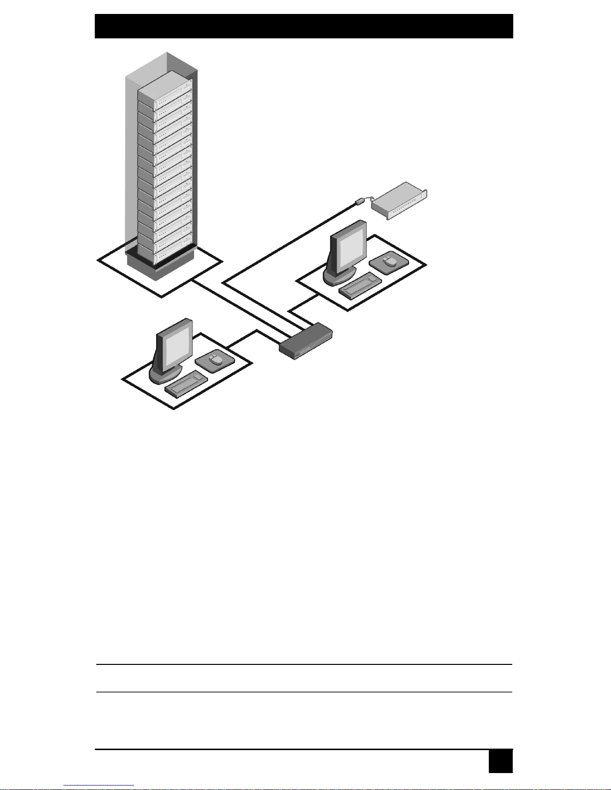
Rack of Servers
SAMs
or ServSelect III
cables
CHAPTER 2: PRODUCT OVERVIEW
Critical server
Analog
Connection
ServSelect III
(KV22016A Shown)
Analog
Connection
Figure 2-1. Example of a ServSelect III Configuration
2.2 Safety Precautions
To avoid potent ial video and/ or keyboard problems when usin g BLACK BOX product s :
• Ιf the building has 3-phase AC power, ensure that the computers and monitors are on
the same phase. For best results, they should be on the same circuit.
• Use only BLACK BOX-supplied cable to connect computers and KVM switches.
To avoid potentially fatal shock hazard and possible damage to equipment, please observe
the following precautions:
• Do not use a 2-wire extension cord in any BLACK BOX product configuration.
• Test AC outlets at the computer and monitor for proper polarity
and grounding.
• Use only with grounded outlets at both the computer and monitor. When using a
backup Uninterruptible Power Supply (UPS), power the computer, the monitor and
the ServSelect III off the supply.
NOTE:
The AC inlet is the main disconnect.
11
Page 14

SERVSELECT III INSTALLER/USER GUIDE
Rackmount safety considerat ions
• Elevated Ambient Temperature: If installed in a closed rack as sembly, the operation
temperature of the rack environment may be greater than room ambient. Use care not
to exceed the rated maximum ambient tempe r ature of the unit.
• Reduced Air Flow: Install at ion of the equipment in a rack should be such that the
amount of airflow required for safe operation of the equipment is not compromised.
• Mechanical Loading: Mounting of the equipment in the rac k should be su ch that a
hazardous condition is not achieve d due to une ven mechanic al loading.
• Circuit Overloading: Consideration should be given to the connection of the
equipment to the sup ply ci rcu it and the effect that overloading o f circu its migh t ha v e
on overcurrent protection and supply wiring. Consider equipment nameplate ratings
for maximum current.
• Reliable Eart hing: Reliable ear thing of rackmounted equipment should be
maintained. Pay particular attention to supply connections other than direct
connections to the branch circuit (for example, use of power strips).
12
Page 15
CHAPTER 3: INSTALLATION
3. Installatio n
3.1 Getting Started
Before installing your ServSelect III switch, refer to the following list to ensure you have
all items that shipped with the appliance as well as other items necessary for proper
installation.
Supplied with the ServSelect III switch
• Power cord
• One null modem serial cab le
• Rackmounting kit
• ServSelect III Installer/User Guide
• ServSelect III Quick Installation Guide
• ServSelect III Cable Quick Installation Guide
Additional items needed
One ServSelect III cable or SAM and UTP cabling per attached server or switch
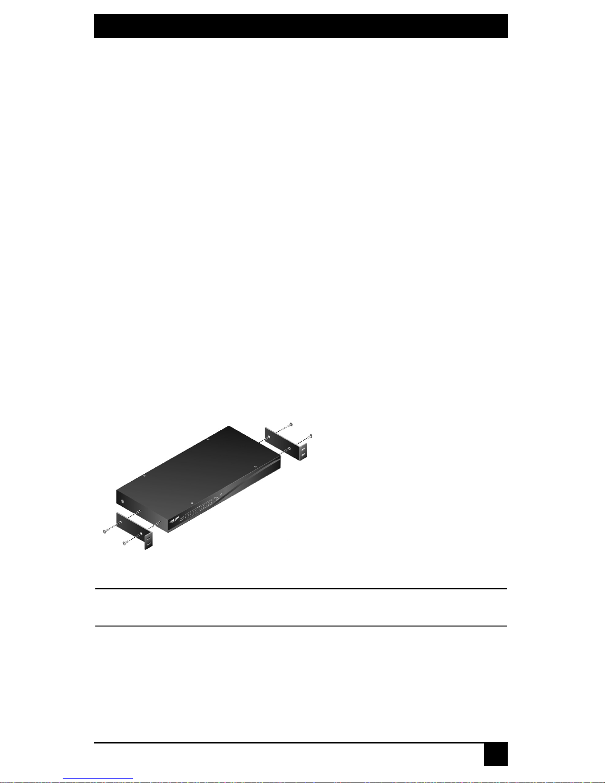
3.2 Rack Mounting Your ServSelect III Switch
Your ServSelect III switch may be rackmounted using the brackets supplied in your
rackmounting kit. Before installing the switch and oth er components in the rack cabinet (if
not already installed), stabilize the rack in a permanent location. Insta ll yo ur eq uipment
starting at the bottom of the rack cabinet, then work to the top.
Figure 3-1. ServSelect III Switch Horizontal Installation
CAUTION:
Rack Loading - Overloading or uneven loading of racks may result in shelf or rack failure, causing
damage to equipment and possible personal injury. Do not exceed your rack load rating.
To install the 1U switch mounting bracket:
1. Remove the first two screws on each side of the switch.
2. Line up the holes in the “long side” of the kit’s side brackets wit h the screw holes in
the switch.
3. With a Phillips screwdriver, fasten the mounting brackets to the switch using two
screws on each side.
13
Page 16

SERVSELECT III INSTALLER/USER GUIDE
4. Attach four cage nuts or clip nuts to the rackmounting flange of the rack cabinet so
that the nut is positioned on the inside of the rack.
NOTE:
Nuts are not included with the rackmount kit.
5. Mount the switch assembly to the r ack cabinet by matching the holes in the “short
side” of each bracket to an appropriate set of matchi ng holes on your rack cabin et.
6. Next, insert the c o mbin ation h ex he a d screws through the slots in the bracket and the
holes in the mounting rail, then into the cage nuts or clip nuts.
3.3 Installing the ServSelect III Switch
Plug the supplied power cord into the back of the appliance and then into an appropriate
power source. Figure 2.1 illustrates one possible configuration for your ServSelect III switch.
CAUTION:
To reduce the risk of electric shock or damage to your equipment -
- Do not disable the power cord grounding plug. The grounding plug is an important safety feature.
- Plug the power cord into a grounded (earthed) outlet that is easily accessible at all times.
- Disconnect the power from the unit by unplugging the power cord from either the electrical outlet or the unit.
14
Page 17
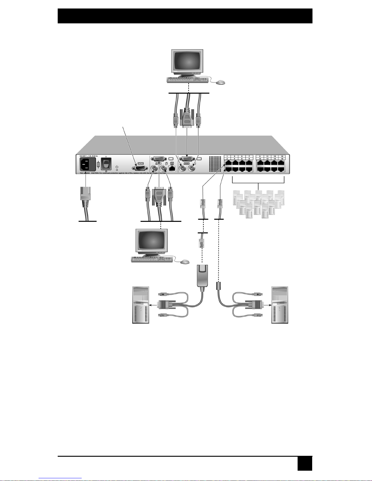
CHAPTER 3: INSTALLATION
Analog User B
Configuration Port
(for updating firmware)
Analog User A
SAM
ServSelect III Switch
(KV22016A Shown)
Servers 3-16
ServSelect III cable
Figure 3-2. Basic ServSelect III Switch Configuration
To connect a server using a SAM:
1. Locate the SAMs for your ServSelect III switch.
2. Attach the appropriately color-coded cable en ds to the keyboard , monitor and mouse ports
on the first server you wi ll be connec ting to the ap pliance.
3. Attach one end of a CAT 5 cable to the RJ45 connector on the SAM.
4. Connect the other end of the CAT 5 cable to the desired port on the back of your
ServSelect III switch.
5. Repeat steps 2 through 4 for each serv er you wish to attach.
Server 1
Server 2
15
Page 18

SERVSELECT III INSTALLER/USER GUIDE
NOTE:
When connecting a Sun SAM, you must use a multi-sync monitor to accommodate Sun computers
that support both VGA and sync-on-green or compos ite sync.
To connect a server using a ServSelect III cable:
1. Locate a ServSelect III cable for the server you wish to connect.
2. Attach the appropriately color-coded cable ends of the ServSelect III cable to the keyboard, monitor and mouse ports on the s erver you will be conne cting to the switch.
3. Attach the other end of the ServSelect III cable to the desired port on the back of your
ServSelect III switch.
4. Repeat steps 1 through 3 for each serv er you wish to attach.
3.4 Connecting Users
To connect local peripherals:
1. Select the keyboard, monitor and mouse to be connected to local an alog user A.
2. Locate the port set labeled A on the back of the appliance. Connect these peripherals
to their respective ports.
3. Bundle and label the cables for easy identification.
4. Repeat these steps for user B, if desired.
3.5 Cascading ServSelect III Switches
You can cascade multiple ServSelect III switches to enable one or two users to connect to
as many as 256 servers. In a cascaded system, each user port on the main ServSelect III
switch will connect to the server port on each cascaded ServSelect III switch. Each
cascaded switch can then be connected to a server with an SAM or ServSelect III cable.
The example shown in Figure 2.3 shows one ServSelect III switch cascaded under the
main switch, enabling the connection of up to 15 primary servers and 16 secondary
servers. Using this configuration, you could cascade 16 ServSelect III switches under the
main switch, enabling the connection of up to 256 servers. Only one level of tiering is
supported in this t ype of configuratio n, which means you can not cascade any additional
legacy switches or another ServSelect III switch.
In this configuration, the l ocal port OSD interface is disabled in switches cascaded below
the main ServSelect III switch.
To cascade multiple ServSelect III switches:
1. Connect the cascaded ServSelect III switch to each server as described in the previous Installing the ServSelect III Switch section.
2. Connect the local peripherals to analog user A and/or B of the main switch as
described in To connect local peripherals.
3. Attach one end of the CAT 5 cabling that will run between your main and cascaded
ServSelect III switch to the RJ45 server port on the cascaded ServSelect III switch.
4. Attach the other end of the CAT 5 cable to one of the RJ45 user ports on the main
ServSelect III switch.
16
Page 19

CHAPTER 3: INSTALLATION
NOTE:
The system will a utomatically “merge” t h e two switches toge ther as one . All servers c onnected to the
cascaded S ervSe lect III s witch wil l displa y o n the m ai n Se rvSele ct I II s witch s erve r list in th e OSD inte rfa ce.
5. Repeat steps 3 and 4 for all additional (secondary ) c ascaded ServSelect III switches
you wish to attach.
Analog User A
Analog User B
ServSelect III Switch
User Ports
15 Primary
Servers
ServSelect III Switch (cascaded)
Figure 3-3. ServSelect III Switch Configuration with a Cascaded Switch
3.6 Adding Legacy Switches
You can add legacy switches to the ServSelect III switching system for easy integration
into your existing confi guration. In a cascaded system, each user port will accommodate
up to 24 servers.
16 Secondary
Servers
17
Page 20

SERVSELECT III INSTALLER/USER GUIDE
SAM
PS/2, USB, Sun and serial
cables are available
ServSele c t II I
SAM
ServSelect II
Server 1
Figure 3-4. ServSelect III Switch Configuration with Legacy KVM Switches
ServSelect IP
Server 2
To add a legacy KVM switch:
1. Mount the primary KVM switch into yo ur rack cabine t.
2. Connect one end of a CA T 5 cable to an available port on the back of your ServSelect
III switch.
3. Attach the keyboard, monitor and mouse connectors of the SAM to a user port on
your cascaded switch.
4. Attach the ot her end of the CAT 5 cabling to the RJ45 connector on the SAM.
5. Connect the servers to your cascaded switch according to the inst ructions included
with the switch.
6. Power cycle the cascaded switch to enable its local user port to recognize the SAM.
7. Repeat steps 2 to 6 for all cascaded switches you wish to attach to your system.
A ServSelect III can also be used as a secondary switch in the configuration shown in Figure 3-4.
To connect local peripherals:
1. Select the keyboard, monitor and mouse to be connected to local us er A.
18
NOTE:
Page 21

CHAPTER 3: INSTALLATION
2. Locate the port set labeled A on the back of the switch. Connect these peripherals to
their respective ports.
3. For the multiuser , 16-port ServSe lect III switch, rep eat steps 1 and 2 for the local a nalog port set labeled B.
4. Bundle and label the cables for easy identification.
3.7 Setting Up Your ServSelect III Switching System
The ServSelect III switching system enables you to auto detect and configure each port on
your appliance. Chapter 4 provides detailed instructions on name customizat ion and OSD
setup and configuration.
19
Page 22

SERVSELECT III INSTALLER/USER GUIDE
20
Page 23

CHAPTER 4: BASIC OPERATIONS
4. Basic Operations
4.1 Controlling Your System at the Analog Ports
The ServSelect III switch features one or two analog port sets on the back of the switch
that allow you to connect a monitor and a PS/2 keyboard and mouse for direct ana log
access. The ServSelect III switch uses the OSD interface, featuring intuitive menus to
configure your system and select servers.
4.2 Viewing and Selecting Ports and Servers
Use the OSD interface Main dialog box to vi ew, configure and control servers in the
ServSelect III switching system. View your servers by name, port or by the unique
Electronic ID number (EID) embedded in each SAM and ServSelect III cable. You will
see an OSD interface-generated port list by default when you first launch the OSD.
The Port column indicates t he user port to which a server is connect ed. If you connect a
legacy KVM switch to the main ServSelect III switch or a cascaded ServSelect III switch,
the port numbering displays the user port first, then the switch port to which the server is
connected. For example, in Figure 3.1, servers 04-03 and 01-02 are connected to switches,
then to servers on ports 03 and 02 respectively.
To access the Main dialog box:
Press Print Screen to launch the OSD interface. The Main dialog bo x disp lays.
Figure 4-1. Example of Configured Main Dialog Box
NOTE:
You can also press the
launch t h e OS D i nterf ace. See Changing Display Behavior later in this chapter for further details. You
can use this key sequen ce in any pl ace you see
Control key twice, th e
Alt
key twice or the
Print Screen
Shift
key twice wit hi n one second to
throughout this insta ller/user guide.
21
Page 24

CHAPTER 4: BASIC OPERATIONS
Viewing the status of your switch
The status of the servers in your system is indicated in the right columns of the
Main dialog box. The following table describes the status symbols.
OSD Interface Status Symbols
Symbol Description
SAMs and ServSelect III cables are online (green circle).
SAMs and ServSelect III cables are offline or are not operating
properly.
Server is cascaded through a cascade legacy switch. The switch is
online and has power.
Server is cascaded through a cascade legacy switch. The switch is
offline or has no power.
SAM is being upgraded (yellow circle).
SAMs and ServSelect III cables are being accessed by the indicated
user channel (green channel letter).
SAMs and ServSelect III cables are blocked by the in dicated user
channel ( bl ac k ch annel letter )
.
Selecting servers
Use the Main dialog box to select servers. When you select a server, the switch
reconfigures the keyboard and mouse to the proper settings for that server.
To select servers:
Double-click the server name, EID or port number.
-or-
If the display order of your server list is by port (Port button is depressed) , type the port
number and press Enter.
-or-
If the display or der of your server list is by na me or EID number ( Name or EID button is
depressed), type the first few characters of the name of the server or the EID number to
establish it as unique and press Enter.
To select the previous server:
Press Print Screen and then Backspace. This key combination toggles you between
the previous and current connections.
22
Page 25

CHAPTER 4: BASIC OPERATIONS
To disconnect the user from a server:
Press Print Screen and then Alt+0. This leaves the user in a free state, with no server
selected. The status f lag on your desktop displays Free.
Soft switching
Soft switching is the ability to switch servers using a hotkey sequence. You can soft switch to a
server by pressing Print Screen and then typing the first few characters of its name or
number.
If you have set a Screen Delay Time and you pr ess the key seq uences before that time has
elapsed, the OSD interface will not display.
To configure servers for soft switching:
1. Press Print Screen to launch the OSD interface. The Main dialog box displays.
2. Click Setup - Menu. The Menu dialog box disp la ys .
3. For Screen Delay Time, type the number of seconds of delay desired before the Main
dialog box is displayed after Print Screen is pressed.
4. Click OK.
To soft switch to a server:
1. To select a server, press Print Screen. If the display order of your ser ver list is by port
(Port button is depressed), type the port number and press Enter.
-orIf the display or der of your server list is by name or EID number (Name or EID but-
ton is depresse d), type the first few characters of the name of the server or the EID
number to est a blish it as unique and press Enter.
2. To switch back to the previous server, press Print Screen then Backspace.
4.3 Navigating the OSD Interface
This table describes how t o navigate the OSD interface u s in g the keyboard and mou se.
OSD Interface Navigation Basics
This Keystroke Does This
Activates the OSCAR interface. See Changing
Print Screen,Ctrl-Ctrl Shift-Shift,
and/or Alt-Alt
Print Screen-Print Screen
the display behavior later in this chapter for
further details.
Press Print Screen twice to send the Print
Screen keystroke to the currently selected
device.
Escape
Closes the current dialog box without saving
changes and returns to the previous one. In the
Main dialog box, it closes the OSD interface
and returns to the flag. In a message box, it
closes the pop-up box and returns to the current
dialog box
23
Page 26

CHAPTER 4: BASIC OPERATIONS
OSD Interface Navigation Basics (Continued)
This Keystroke Does This
F1 Opens the Help screen for the dialog box.
Opens dialog boxes, selects or checks options
Alt+Hotkey
and executes actions when used with underlined
or other designated letters.
Alt+X
Alt+O
Single-click, Enter
Enter
Print Screen, Backspace Toggles back to previous selection.
Print Scree n , Alt+0
(zero)
Print Scree n, Pause
Closes the current dialog box and returns to the
previous one.
Selects the OK button, then returns to the
previous dialog box.
In a text box, selects the text for editing and
enables the Left and Right Arrow keys to move
the cursor. Press Enter again to quit the edit
mode.
Completes a switch in the Main dialog box and
exits the OSD interface.
Immediately disengages a user from a server; no
server is selected. Status flag displays Free.
(This only applies to the 0 on the keyboard and
not the keypad.)
Immediately turns on screen saver mode and
prevents access to that specific console, if it is
password protected.
Up/Down Arrows Moves the cursor from line to line.
Moves the cursor between columns. When
Right/Left Arrows
Page Up/Page Down
Home/End Moves the cursor to the top or bottom of a list.
Delete Deletes characters in a text box.
Page Up/Page Down
Numbers Type from the keyboard or keypad.
Print Screen, Ctrl+ F4
editing a text box, these keys move the cursor
within the column.
Pages up and down through Name and Port lists
and Help pages.
Pages up and down through Name and Port lists
and Help pages.
Logs the current user out of the switch (only
available when Enable Local User Accounts is
checked on the Security screen).
24
Page 27

CHAPTER 4: BASIC OPERATIONS
4.4 Configuring OSD Interface Menus
You can configure your ServSelect III switch from the Setup menu within the OSD
interface. Select the Names bu tton when initially sett ing up your switch to iden tify server s
by unique names. Select the other setup features to manage routine tasks for your servers
from the OSD interface menu.
Setup Features to Manage Routine Tasks for Your Servers
Feature Purpose
Change the server listing between numerically
by port or EID number and alphabetically by
Menu
name. Change the Screen Delay Time before the
OSD interface displays after pressing Print
Screen.
Flag
Broadcast
Scan
Security
Devices
Names Identify servers by unique names.
Switch
Keyboard
User
Change display, timing, color or location of the
status flag.
Set up to simultaneously control multiple servers
through keyboard and
mouse actions.
Set up a custom scan pattern for up to 16
servers.
Set passwords to restrict server access. Enable
the screen saver.
Identify the appropriate number of ports on an
attached cascaded switch.
Choose the switch mode and the share mode
time-out.
Choose the keyboard country code that is sent
to the SAM or ServSelect III cables.
Allows the administrator to set up the Local User
Accounts (only visible when Enable Local User
Accounts is checked on the Security screen).
Only the Menu, Flag and Security screens are available to the users without administrator privileges. All
other screens, except the Us er screen, are available to the administrator when Enab le Local Us er Account s
To access the Setup menu:
1. Press Print Screen to launch the OSD interface. The Main dialog box displays.
NOTE:
is disabled in the Security screen.
25
Page 28

CHAPTER 4: BASIC OPERATIONS
2. Click Setup. The Setup dialog box displays.
Figure 4-2. Setup Dialog Box
Assigning server names
Use the Names dialog box to identify individual servers by name rather than by port
number. The Names list is always sorted by port order. Names are st ored in the SAM or
ServSelect III cable, so even if you move the module/cable to another user port, the name
and configura ti on will be recogni zed by the switch.
NOTE:
If a server is turned off, its respective SAM or ServSelect III cable will not appear in the Names list.
To access the Names dialog box:
1. Press Print Screen to launch the OSD interface. The Main dialog box will appear.
2. Click Setup - Names. The Names dialog box displays.
Figure 4-3. Names Dialog Box
If the server list changes, the mouse cursor will turn into an hourglass as the list is automatically updated. No mouse
or keyboard input will be accepted until the list update is complete.
NOTE:
26
Page 29

CHAPTER 4: BASIC OPERATIONS
To assign names to servers:
1. In the Names dialog box, select a server name or port number and click Modify. The
Name Modify dialog box displays.
Figure 4-4. Name Modify Dialog Box
2. T ype a name in the New Na me box . Names of server s may be up to 15 char acter s long.
Supported char a c ter s inc l ud e: A to Z, a to z, 0 to 9, space a nd hyphen.
3. Click OK to transfer the new name to the Names dialog box. Your selection is not
saved until you click OK in the Names dialog box.
4. Repeat steps 1 to 3 for each server in the system.
5. Click OK in the Names dialog box to save your changes.
-orClick X or press Escape to exit the dialog box with out saving chan ges.
NOTE:
If a SAM has not been assigned a name, the EID is used as the default name.
Assigning device types
The ServSelect III switch automatically discovers cascaded KVM switches, but you will
need to specify the number of ports on the casca ded switch throu gh the Device s dialo g b ox.
You will see an Sw-8 or Sw-24 display in the Ty pe cate gory for the cascad ed switch. Se le ct
the switch from the list and the Modify butto n d isplay s, allo wing y ou to a ssign it the
appropriate number of ports.
NOTE:
The Modify button will only be available if a configurable switch is selected.
To acce ss the Devi ces d ialog box:
1. Press
Print Screen to launch the OSD interface. The Main dialog box will
appear.
2. Click Setup - Devices. The Devices di alog box di splays .
27
Page 30

CHAPTER 4: BASIC OPERATIONS
Figure 4-5. Devices Dialog Box
When the ServSelect III switch discovers a cascaded switch, you will notice the port
numbering change t o accommodate each serve r u nder that switch. For example, if t he
switch is connected to user port 6, the switch port would be l isted as 06 and each ser ver
under it would be numbered sequent ially 06-01, 06 -02 and so on.
To assign a device type:
1. In the Devices dialog box, select the desired port number.
2. Click Modify. The Device Modify dialog box displ a ys.
Figure 4-6. Device Modify Dialog Box
3. Choose the number of ports supported by your cascaded switch and click OK.
4. Repeat steps 1 to 3 for each port requiring a devi ce type to be assigned.
5. Click OK in the Devices dialog box to save settings.
Changes made in the Device Modify dialog box are not saved until you click OK in the Devices
NOTE:
dialog box.
28
Page 31

CHAPTER 4: BASIC OPERATIONS
Changing the display behavior
Use the Menu dialog bo x to chang e the dis play orde r of serv ers , change the key s equen ce
to launch the OSD interface
display order setting alters how servers will display in seve ral screens includ ing the Main,
Devices and Broadcast dialog boxes.
To access the Menu dialog box:
1. Press Print Screen to launch the OSD interface. The Main dialog box displays.
2. Click Setup - Menu in the Main dialog box. The Menu dialog box displays.
and set a Screen Delay Time for the OSD interface. The
Figure 4-7. Menu Dialog Bo x
To choose the default display order of servers:
1. Select Name to display servers alphab et ically by name.
-orSelect EID to di splay servers numerically by EID number.
-orSelect Port to display servers numerically by port number.
2. Click OK.
To set up key sequences to launch the OSD interface:
1. Click the box next to the key sequence you want to start the OSD interface.
Unchecking all boxes will leave
2. Click OK.
To set a Screen Delay Time for the OSD interface:
1. Type in the number of seconds (0 to 9) to delay the OSD interface display after you press
Print Screen. Entering 0 will instantly launch the OSD interface with no delay.
2. Click OK.
Setting a Screen Delay Time allows you to complete a soft switch without the OSD
interface displaying. To perform a soft switch, see Soft switching in this chapter.
Print Screen as the default.
29
Page 32

CHAPTER 4: BASIC OPERATIONS
Controlling the status flag
The status flag displays on your desktop and shows the name or EID number of the
selected server or the status o f th e sel ected port. Use the Flag dialog box to configure the
flag to display by server name or EID number, or to change the flag color, opacity, display
time and location on the desktop.
OSD Interface Status Flags
Flag Description
Flag type by name
Flag type by EID number
Flag indicating that the user has been
disconnected from all systems
Flag indicating that broadcast mode is
enabled
To access the Flag dialog box:
1. Press Print Screen. The Main dialog box will appear.
2. Click Setup - Flag. The Flag dialog box displays.
Figure 4-8. Flag Dialog Box
To determine how the status flag is displayed:
1. Select Name or EID to determine what information will be displayed.
2. Select Displayed to show the flag all the time or select Timed to display the flag for
only five seconds after switching.
3. Select a flag color in Display Color.
30
Page 33

CHAPTER 4: BASIC OPERATIONS
4. In Display Mode, select Opaque for a solid color flag or select Transparent to see the
desktop thr o ugh the flag.
5. To position the status flag on the desktop:
a. Click Set Position to gain access to the Set Position Flag screen.
b. Left-click on the title bar and drag to the desired location.
c. Right-click to return to the Flag dialog box.
Figure 4-9. Set Position Flag
NOTE:
Changes made to the flag position are not saved until you click OK in the Flag dialog box.
6. Click OK to save settings.
-orClick X to exit without saving changes.
Setting console security
The OSD interface enables you to set security on your analog port console. You can
establish a screen saver mode that engages after your console remains unused for a
specified Inactivity Time. Once engaged , your console will remain locked until you press
any key or move the mouse. You will then need to type in your password to continue.
Use the Security dialog box to lock your cons ole with password protection, set or change
your password and enable the screen saver.
NOTE:
If a password has been previously set, you will have to enter the password before you can acce ss the
Security dialog box. If you should lose or forget your password, please contact BLACK BOX Technical
Support about returning your switch for service.
To access the Security dialog box:
1. Press Print Screen to launch the OSD interface. The Main dialog box will appe a r.
2. Click Setup - Security. The Security dialog box displays.
31
Page 34

CHAPTER 4: BASIC OPERATIONS
Figure 4-10. Security Dialog Box
NOTE:
Figure 4-10 is the Security screen for the administrator and local user when the Enable User Account s
feature is turned off. The restricted user can only access the Change Pa ssword function of this screen.
To set or change th e password:
1. Single -c lic k and press Enter or double-click in the New text box.
2. Type the new password in the New text box and press Enter.
Passwords must contain both alpha and num e ric characters, ar e case sensitiv e and may
be up to 12 characters long. Supported characters are: A to Z, a to z, 0 to 9 , space and
hyphen.
3. In the Repeat box, type the password again and press Enter.
4. Click OK to change only your password, and then close the dialog box.
To password protect your console:
1. Set your password as described in the previous pr ocedure.
2. Select Enable Screen Saver.
3. Type the number of minutes for Inactivity Time (from 1 to 99) to delay activation of
password protection an d t he screen saver feature.
4. For Mode, select Energy if your monitor is E
NERGY STAR
®
compliant; otherwise
select Screen.
CAUTION:
Monitor damage can result from the use of Energy mode with monitors not compliant with
ENERGY STAR.
5. (Optional) Click Test to activate the screen saver test which lasts 10 seconds then
returns you to the Security dialog box.
6. Click OK.
To log in to your console:
1. Press an y key or move the mous e .
2. The Password dialog box displays. Type your password, then click OK.
3. The Main dialog box displays if th e password was entered properly.
32
Page 35

CHAPTER 4: BASIC OPERATIONS
To remove password protection from your console:
1. From the Main di alog box, cli ck Setup - Security; the Password dialog box displ ays.
Type your password, then click OK.
2. In the Security dialog box, single- c lic k an d pre s s Enter or double-c lick in the New
box. Leave the box blank. Press Enter.
3. Single- click a nd p ress Enter or double-click in the Repeat box. Leave the box blank.
Press Enter.
4. Click OK to eliminate your passwor d.
To en able lo cal user acc ounts:
1. Click the Enable Local User Accounts checkbox.
2. Click OK.
To disable local user accounts (admin user only):
1. Click Enable Local User Accounts to uncheck the box and disable this
option.
2. Click OK.
To enable the screen saver mode with no password protection:
1. If your console does not require a password to gain access to the Security dialog box,
proceed to step 2.
-orIf your console is password pr otected, see the previous procedure, then go to step 2.
2. Select Enable Screen Saver.
3. Type the number of minutes for Inactivity Time (from 1 to 99) to delay activation of
the
screen saver.
4. Choose Energy if your monitor is E
CAUTION: Monitor damage can result from the use of Energy mode with monitors not compliant with
NERGY STAR compliant; otherwise select Screen.
ENERGY STAR.
5. (Optional) Click Test to activate the screen saver test which lasts 10 seconds then
returns you to the Security dialog box.
6. Click OK.
NOTE:
Activation of the screen saver mode disconnects the user from a server; no server is selected. The status
flag displays Free.
To exit the screen saver mode:
Press an y ke y or m ove you r m ouse . The Main di alog box disp lays an d an y pre viou s s erve r
connection will be restored.
To turn off the screen saver:
1. In the Security dialog box, clear Enable Screen Saver.
2. Click OK.
33
Page 36

CHAPTER 4: BASIC OPERATIONS
To immediately t urn on the screen saver:
Press Print Screen, then press Pause.
4.5 Displaying Version Information
The OSD interface enables you to display the versions of the ServSelect III switch, as
well as the SAM and ServSelect III cable firmware. For optimum performance, keep
your firmware current. For more information, see Appendix A.
To display version information:
1. Press Print Screen. The Main dialog box will appea r.
2. Click Commands - Display Versions. The Version dialog box displays. The top half of
the box lists the subsystem versions in the app liance.
Figure 4-11. Version Dialog Box
3. Click the Target button to view individual SAM and ServSelect III cable version
information. The Target Selection dialog box displays.
Figure 4-12. Target Selection Dialog Box
4. Select an SAM or ServSelect III cable to view and click the Version button. The
Target Version dialog box displays. For more information on loading firmwar e , see
Appendix A.
34
Page 37

CHAPTER 4: BASIC OPERATIONS
Figure 4-13. Target Version Dialog Box
5. Click X to close the Target Version dialog box.
NOTE:
Load Firmware button will only display for a SAM; ServSelect III cables are not upgradable.
administrator and the user (when local user accounts are disabled) can upgrade the firmware on a SAM.
Only the
4.6 Scanning Your System
In scan mode, the appli ance automatically scans from port to port (server to server). You
can scan up to 16 servers, specifying which servers to scan and the number of seconds that
each server will display. The scanning order is determined by placement of the server in
the list. The list is always shown in scanning order. You can, however, choose to display
the server’s name or EID number by pressin g the appropriate button.
To add servers to the scan list:
1. If the OSD interfa ce is not open, pre ss Print Screen. The Main dialog box will
appear .
2. Click Setup - Scan. The Scan dialog box displays.
Figure 4-14. Scan Dialog Box
3. The dialog box co nta ins a listing of all servers a ttac he d to yo ur ap plia nc e. Cli ck the
checkbox next to the s erv ers you wish to scan.
35
Page 38

CHAPTER 4: BASIC OPERATIONS
-orDouble-click on a serve r’s name or port.
-orPress Alt and the nu mber o f the ser ver yo u wish to sc an. You can selec t up to 1 6 server s
from the entire list.
4. In the Scan Time box, type the number of seconds (from 3 to 99) of desired time
before the scan moves to the next server in the sequence.
5. Click OK.
To remove a server from the scan list:
1. In the Scan dialog box, deselect the checkbox next to the server to be removed.
-orDouble-click on the server’s name or po rt.
-orClick the Clear button to remove all servers from the scan list.
2. Click OK.
To start the scan mode:
1. If the OSD interfa ce is not open, pre ss Print Screen. The Main dialog box will
appear.
2. Click Commands. The Commands dialog bo x disp la ys .
Figure 4-15. Commands Dialog Box
Figure 4-15 shows the Commands screen for the administrator and local user when the Enable User
Accounts feature is turned off. The restricted user will only have access to t he Display Versions, Device
3. Select Scan Enable in the Comman ds dialog box.
4. Click X to close the Commands dialog box.
Scanning will begin when the Main dialog box or flag is displayed. Scanning is inhibited in any other OSD
NOTE:
Reset and Log Out buttons.
NOTE:
interface dialog box.
36
Page 39

CHAPTER 4: BASIC OPERATIONS
To cancel scan mod e:
1. Select a server if the OSD interface i s open.
-orMove the mouse or press any key on the keyboard if the OSD interface is not open.
Scanning will stop at the currently selected server.
2. Press Print Screen. The Main dialog box will appea r.
3. Click Commands. The Commands dialog bo x disp la ys .
4. Clear Scan Enable.
4.7 Running System Diagnostics
You can validate the integr ity of y our system throu gh the Run Dia gno stics comma nd. This
command checks the main bo ard func tion al sub- system s (memory, communications, switch
control and the video channels) for each system controller. When you select the Run
Diagnostics option, you will receive a warning indic ating th at all use rs (remo te and loc al)
will be disconnected. Click OK to c onfirm and begin the test.
The Diagnost ic s dialog box displays. The top section of the dialog box disp la ys t he
hardware tests. The bottom portion divides the tested SAM and ServSelect III cables into
three categories: On-line, Offline or Suspect.
SAM or ServSelect III cables may appear to be of fline while being upgraded.
Figure 4-16. Diagnostics Dialog Box
NOTE:
37
Page 40

CHAPTER 4: BASIC OPERATIONS
Next to each item to be tested, you will see a pass (green circle) or fail (red x) symbol
display to the left of each item as that test finishes. The following table details each of the
tests.
Diagnostic Test Details
Test Description
Memory Test s
Firmware CRCs
Comm Interfaces
Switch Controller test
Local Video
On-line Targets
Offline Targets
Suspect Targets
Reports on the condition of the main
board RAM
Reports on the condition of the main
board RAM
Validates the current firmware images
stored in the system’s Flash
Verifies the switch matrix controller is
accessible and functional
Indicates the condition of the local
video monitor
Indicates the total number of currently
connected and powered targets
Indicates the number of targets that
have been connected successfully in
the past and are powered down
Indicates the number of targets that
have been detected, but are either
unavailable for connection or have
dropped packets during the ping tests
To run diagnostic tests:
1. If the OSD interfa ce is not open, pre ss Print Screen. The Main dialog box will
appear.
2. Click Commands - Run Diagnostics. A warning message displays indicating that all
users will be disconnected.
38
Page 41

CHAPTER 4: BASIC OPERATIONS
Figure 4-17. Diagnostics Warning Dialog Box
3. Click OK t o begin diagnost ics.
-orClick X or press Escape to exit the dialog box without running a diagnostic test.
4. All users are disconnec ted and the Diagnostics dialog box displays .
5. As each test is finished, a pass (green circle) or fail (red x) symbol disp lays. The test
is complete when the last test’s symbol displays.
4.8 Broadcasting to Servers
The analog user can simultaneously control more th an one server in a system to ensure
that all selected servers receive identical input. You can choose to broadcast keystrokes
and/or mouse movements independently.
NOTE:
You can broadcast to up to 16 servers at a time, one server pe r user port.
To access the Broadcast dialog box:
1. Press Print Screen. The Main dialog box will appea r.
2. Click Setup - Broadcast. The Broadcast dialog box displays.
Figure 4-18. Broadcast Dialog Box
39
Page 42

CHAPTER 4: BASIC OPERATIONS
NOTE:
Broadcasting Keystrokes -
interpret keystrokes identically. S pecifically, the
keyboards. While the appliance attempt s to send ke ystrokes to the selected servers simu ltaneousl y, some
Broadcasting Mouse Movement s -
mouse drivers, desktops (such as identically placed icons) and video resolutions. In addition, the mouse
must be in exactly the same place on all screens. Because these conditions are extremely difficult to
achieve, broadcasting mouse movem ent s to multiple systems may have unpredictable results.
The keyboard state mus t be identical for all se rvers rece iving a broadcas t to
Caps Lock
servers may inhibit and thereby delay the transmission.
NOTE:
For the mouse to work accurately, all systems must have identical
and
Num Lock
modes must be the same on all
To broadcast to selected servers:
1. From the Broadcast dialog box, select the mouse and/or keyboard checkboxes for the
servers that are to receive the broadcast commands.
-orPress the Up or Down Arrow keys to move the cursor to the target server. Then
press Alt+K to select the keyboard chec kbox and/or Alt+M to select the mouse
checkbox. Repeat for additional servers.
2. Click OK to save the settings and return to the Setup dialog box. Click X or press
Escape to return to the Main dialog box.
3. Click Commands. The Commands dialog bo x disp la ys .
4. Click the Broadcast Enable checkbox to activate broadcasting. The Broadcast Enable
Confirm/ D en y dia lo g bo x dis plays.
Figure 4-19. Broadcast Enable Confirm/Deny Dialog Box
5. Click OK to enable the broadcast. Click X or press Escape to cancel and return to
the Commands dia log box.
6. If broadcasting is enabled, type the information and/ or perform the mouse movements you want to broadcast from the switch. Only servers in the list are accessible.
The other user is disabled when broadcast mode is enabled.
To turn broadcasting off:
From the Commands dialog box, clear the Broadcast Enable checkbox.
NOTE:
40
Page 43

CHAPTER 4: BASIC OPERATIONS
4.9 Changing Your Switch Mode
Your ServSelect III switch allows you to connect to attached servers using two methods:
Preemptive and Cooperative.
Select Preemptive (default setting) to allow any user to select any server at any tim e; a
request from an othe r us e r disco nnects the current u se r w itho ut w arn ing.
-or-
Select Cooperative to maintain the current user connection; the current user will not be
disconnected if another user requests connecti on.
To access the Switch dialog box:
1. Press Print Screen. The Main dialog box will display.
2. Click Setup - Switch. The Switch dialog box displays.
Figure 4-20. Switch Dialog Box
3. Select either Preemptive or Cooperative as your switch mode.
4. Click OK to sav e changes. Click X or press Escape to cancel.
Setting the Share Mode feature
The Share Mode feature of the ServSelect III switches allows two users to gain
access to a primary server.
To en able Sh ar e Mode :
1. Press
Print Screen. The Main dialog box will display.
2. Click Setup - Switch. The Switch dialog box displays.
3. Select Share Enable from the Switch dialog box.
4. Choose the amount of inactivity time for the target (up to 600 seconds)
before another user can take control of the target.
5. Click OK to save changes. Click X or press Escape to cancel.
41
Page 44

CHAPTER 4: BASIC OPERATIONS
42
Page 45

SERVSELECT III INSTALLER/USER GUIDE
5. Advanced Operations
5.1 Using Administrator Privileges
The ServSelect III switches allow up to four users and one administrator to log into a
switch, with the administrator having the ability to restric t users from accessing the targets
via the Security menu. The administrator can edit, access and/or delete us er accounts.
Figure 5-1. Security Menu
To access the User Setup screen (administrator only):
1. Click the Enable User Account checkbox in the Securit y me nu . Th e Setup m en u will
appear.
2. Click the OK button.
3. Click the User button on the Setup screen to enter the User Setup screen.
NOTE:
Clicking the User button on the Setup screen will automatically log out any currently logged in user.
Other users will remain logged out until your changes are complete.
Figure 5-2. Setup Menu (Administrator Only)
43
Page 46

CHAPTER 5: ADVANCED OPERATIONS
Figure 5-3. User Setup Menu (Administrator Only)
User Setup menu functions (administrator only)
The User Setup menu allows the administrator to edit, access and/or delete a user account.
The menu is only accessi ble if the Enable User Acco unt checkbox is enab led in the
Security menu. The ServSelect III switches will have four standa rd user accounts, with the
default names of User1, User2, User3 an d User4.
To edit a user:
1. Click the username of the user to be modified .
2. Click Edit to change the username and / or pa s s w ord of the selected user.
3. Click Access to restrict port access for the selected user.
4. Click Delete to restor e th e sel ected user to the default state (default name, no password, no port access).
5. Click OK on the User Setup screen to save changes, or click the Exit button to escape
without saving any changes.
User Edit menu (administrator only)
The Edit men u a llo ws th e ad mi nis tr a to r to se t or c h an ge us e r na m e s an d p ass w o rds f or a ll
users.
Figure 5- 4. User Edit M e n u (Admin is trator O nl y )
44
Page 47

SERVSELECT III INSTALLER/USER GUIDE
The Username fie ld dis p la ys def a ult na m es tha t ca n be edite d by the administrator.
Usernames must be between 1 to 15 ch aracters. Administrators can also set user
passwor ds in t he Use r Ed it men u. Pas swo rds must be be twee n 5 to 12 char ac ters and m ust
contain at least one number and one alpha charact er. Administrators must veri fy new
passwords by retyping the passwor d in the Repeat Password field.
NOTE:
Changes are not saved until the administrator clicks OK in the User Setup menu.
User Access menu (administrator only)
The Access menu displays ea ch user name, port number and whether the user has access
to the listed KVM ports. The admi ni strator controls which ports are accessible to which
user by clicking in the ap propriate checkbox.
Figure 5-5. User Access Menu (Administrator Only)
The Clear All button allows the administrator to cle ar access to all ports for a given user
instead of deleting the account. The Check All button allows the administrator to assign
all available KVM ports to any user.
NOTE:
Changes are not saved to memory until the administrator clicks OK on the User Setup screen.
User Setup menu - Delete (administrator only)
The Delete button in the User Access menu allows an administrator to delete user
accounts. Simply select an account from the menu and click the Delete button. The deleted
user account will immediately return to default settings.
45
Page 48

CHAPTER 5: ADVANCED OPERATIONS
46
Page 49

SERVSELECT III INSTALLER/USER GUIDE
Appendix A: Flash Upgrade s
Upgrading the ServSelect III
You can upgrade the firmware of your ServSelect III by using a special update utility
provided by BLACK BOX. Th is utilit y autom atically configu res th e port c ommunica tions
settings to allow direct downloading from the connected server.
Items needed for the upgrade
• Server running Windows NT®, Windows® 95, Windows 98 or Windows 2000
• Available serial port (COM port) on the server
• Null modem serial cable that connects the switch and the server
• Firmware update
To upgrade firmware:
1. Connect the null modem serial cable to a COM port on the server and to the serial
connector on the back panel of the switch. Make a note of which COM port you have
chosen, then turn on the switch.
2. Go to www.blackbox.com to access the firmware upgrade file. Once the download is
complete, navigate to the drive where you have saved the firmware update and unzip
the file.
3. Double-click to run the file ApplianceUpdate.exe.
4. Click the Next button to display the main dialog box.
5. In the dialog box that dis pla ys , se le ct the desired languag e fro m the selected
Language drop-down list a nd the appr opri ate COM Port fro m the COM Port
menu.
6. Click Update.
7. Once the firmware is updated, an Update Complete message displays. Click
the Close button
to exit the dialog box.
8. The switch automatically reboots after the upgrade is completed.
Possible error conditions
If the download does not execute properly, verify the following:
• Verify that the COM port is correct.
• Verify that no other program is currently using the COM port, or that no previous
DOS window/shel l is open that had used the desi red COM port.
• Verify that no other copies of the Appliance Update utility are currently running.
• Verify that a null modem serial cable is used.
• In the selected COM port Advanced Port settings, verify that the FIFO buff-
ers are selected and that the receive buffer is set to High.
While upgrading, do not use your computer for anything else or switch between windows. Close all other
windows if necessary. If the upgrade was unsuccessful (such as during a power outage), repeat
47
CAUTION:
the procedure.
Page 50

APPENDICES
Upgrading the SAM firmware
The SAMs can be upgraded individually or simultaneously.
NOTE:
ServSelect III cables are not upgrada ble.
To simultaneously upgrade multiple SAMs:
1. Press Print Screen. The Main dialog box will appea r.
2. Click Commands - SAM Status. The SAM Status dialog box displays.
Figure 1-1. SAM Status Dialog Box
3. Click one or more types of mod ules to upgrade. Click Upgrade.
4. The SAM Upgrade dialog box displays. Click OK to initiate the upgrade and retu rn to
the SAM Status dialog box.
Figure 1-2. SAM Upgrade Dialog Box
To upgrade SAM firmware individually:
1. Press Print Screen. The Main dialog box will ap pe ar.
2. Click Commands - Display Versions . The Version dialog box displays.
48
Page 51

SERVSELECT III INSTALLER/USER GUIDE
Figure 1-3. Version Dialog Box
3. Click Target to view individual SAM information. The Target Selection dialog
box displays.
Figure 1-4. Target Selection Dialog Box
4. Select an SA M to upgrade and click the Version button. The Target Version dialog
box displays.
Figure 1-5. Target Version Dialog Box
49
Page 52

APPENDICES
5. Click the Load Firmware button. The SAM Load dialog box displays.
NOTE:
The Load Firmware button displays for SAMs only; ServSelect III cables are not upgradable.
Figure 1-6. SAM Load Dialog Box
6. Click OK to initiate the upgrade and return to the Status dialog box.
NOTE:
During an upgrade, the SAM status indicator in the Main dialog box will be yellow. The SAM is unavailable
while an upgrade is in progress. When an upgrade is initiated, any current connection to the server via the
SAM will be terminated.
50
Page 53

NOTES
51
Page 54

NOTES
52
Page 55

Page 56

For FREE Technical Support 24 hours a day, 7 days a week, call 724-746-5500 or fax 724-746-0746
Mailing address: Black Box Corporation, 1000 Park Dr., Lawrence, PA 15055-1018
World-Wide Web: www.blackbox.com • Email: info@blackbox.com
© Copyright 2006. Black Box Corporation. All rights reserved.
Doc. No. 590-598-501A
Customer Support Information:
 Loading...