

Black Box KV1713E, KV1700A, KV1700E, KV1702A, KV1701A User Manual
...
APRIL 2007
KV1700A/E
KV1701A/E
KV1702A/E
KV1703A/E
KV1711A/E
KV1711A/E-R2
KV1712A/E
KV1712A/E-R2
KV1713A/E


1
SERVSWITCH
TM
FAMILY
Welcome to the ServSwitch Family!
Thank you for purchasing a BLACK BOX Octet! We appreciate your business, and we
think you’ll appreciate the many ways that your new Octet will save you money, time,
and effort.
That’s because the ServSwitch family is all about breaking away from the traditional,
expensive model of computer management. You know, the one-size-fits-all-even-if-itdoesn’t model that says, “One computer gets one user station, no more, no less.” Why not a
single user station (monitor, keyboard, and mouse) for multiple computers—even computers
of different platforms? Why not a pair of user stations, each of which can control multiple
computers? Why not multiple user stations for the same computer?
With our ServS witch products, there’s no reason why not. We carry a broad line of robust
solutions for all these applications. Do you have just two PCs, and need an economical
alternative to keeping two monitors, keyboards, and mice on your desk? Or do you need to
share dozens of computers, including a mix of IBM® PC, RS/6000®, Apple®
Macintosh®, Sun Microsystems®, and SGI™ compatibles among multiple users with
different access levels? Does your switch have to sit solidly on a work table and use
regular everyday cables? Or does it have to be mounted in an equipment rack and use
convenient many-to-one cables? No matter how large or small your setup is, no matter
how simple or how complex, we’re confident we have a ServSwitch system that’s just
right for you.
The ServSwitch
family from BLACK BOX—the one-stop answer for all your KVM
switching needs!
*
This manual will tell you all about your new ServSwitch Octet, including how to install,
operate, and troubleshoot it. For an introduction to the ServSwitch Octet, see Chapter 2.
The ServSwitch Octet product codes covered in this manual are:
KV1700 KV1701 KV1702 KV1703 KV1711 KV1711-R2 KV1712
KV1712-R2 KV1713
This manual also includes information about the ServSwitch Octet software and the Server
Access Modules (SAM), whi ch have their own manuals or installation guides.
KV1720 KV1721 KV1724 KV1725
KV1726 KV1727 PS123
NOTE:
For ServSwitch Octet products in the United States, product codes will end w ith the letter A. For ServSwitch
Octet products outside of the United States, product codes will end with the letter E.

SERVSWITCH
TM
OCTET INSTALLER/USER GUIDE
2
FEDERAL COMMUNICATIONS COMMISSION
AND INDUSTRY CANADA
RADIO-FREQUENCY INTERFERENCE ST ATEMENTS
This equipment generates, uses, and can radiate radio-frequency energy and if not
installed and used properly, that is, in strict accordance with the manufacturer’s
instructions, may cause interference to radio communication. It has been tested and found
to comply with the limits for a Class A computing device in accordance with the
specifications in Subpart B of Part 15 of FCC rules, which are designed to provide
reasonable protection against such interference when the equipment is operated in a
commercial environment. Operation of this equipment in a residential area is likely to
cause interference, in which case the user at his own expense will be required to take
whatever measures may be necessary to correct the interference.
Changes or modifications not expressly approved by the party responsible for compliance
could void the user’s authority to operate the equipment.
This digital apparatus does not exceed the Class A limits for radio noise emission from
digital apparatus set out in the Radio Interference Regulation of Industry Canada.
Le présent appareil numérique n’émet pas de bruits radioélectriques dépassant les limites
applicables aux appareils numériques de la classe A prescrites dans le Règlement sur le
brouillage radioélectrique publié par Industrie Canada.
EUROPEAN UNION DECLARATION OF CONFORMITY
This equipment has been tested and found to comply with the limits for a Class A
computing device in accordance with the specifications in the European standard
EN55022. These limits are designed to provide reasonable protection against harmful
interference. This equipment generates, uses and can radiate radio-frequency energy, and
if not installed and used in accordance with the instructions, might cause harmful
interference to radio or television reception.
However, there is no guarantee that harmful interference will not occur in a particular
installation. If this equipment does ca use interference to radio or television reception,
which can be determined by turning the equipment on and off, you can correct the
interference with one or more of the following measures:
a. Reorient or relocate the receiving antenna.
b. Increase the separation between the equipment and the receiver.
c. Connect the equipment to an outlet on a circuit different from tha t to which the receive r
is connected.
d. Consult the supplier or an experienced radio/TV technician for help.
3
COMPLIANCE STATEMENTS
Shielded cables must be used with this equipment to maintain compliance with radio
frequency energy emission regulations and ensure a suitably high level of immunity to
electromagnetic disturbances. This equipment has also been found to comply with
European standards EN50082 and EN60950.
Japanese Compliance Statement
Other Agency Approvals
USA (UL, FCC)
Canada (cUL, ICES-003)
European Union (CE)
TRADEMARKS USED IN THIS MANUAL
BLACK BOX® and the logo are registered trademarks, and ServSwitch, ServSelect, and
ServSelect IP are trademarks of BLACK BOX Corporation.
Apple, Mac, and Macintosh are registered trademarks of Apple Computer, Inc.
IBM, PS/2, and RS/6000 are registered trademarks of International Business
Machines Corporation.
Microsoft, HyperTerminal, Windows, Windows NT, and Windows XP are trademarks or
registered trademarks of Microsoft Corporation in the United States and/or other countries.
Sun and Sun Microsystems are registered trademarks of Sun Microsystems, Inc. in the
United States and other countries.
UL is a registered trademark of Underwriters Laboratories Inc.
Any other trademarks mentioned in this manual are acknowledged to be the property of
the trademark owners.

SERVSWITCH
TM
OCTET INSTALLER/USER GUIDE
4
Normas Oficiales Mexica n as (NO M)
Electrical Safety Statement
INSTRUCCIONES DE SEGURIDAD
1. Todas las instrucciones de seguridad y operación deberán ser leídas antes de que el
aparato eléctrico sea operado.
2. Las instrucciones de seguridad y operación deberán ser guardadas para
referencia futura.
3. Todas las advertencias en el aparato eléctrico y en sus instrucciones de operación
deben ser respetadas.
4. Todas las instrucciones de operación y uso deben ser seguidas.
5. El aparato eléctrico no deberá ser usado cerca del agua—por ejemplo, cerca de la tin a
de baño, lavabo, sótano mojado o cerca de una alberca, etc.
6. El aparato eléctrico debe ser usado únicamente con carritos o pedestales que sean
recomendados por el fabricante.
7. El aparato eléctrico debe ser montado a la pared o al techo sólo como sea
recomendado por el fabricante.
8. Servicio—El usuario no debe intentar dar servicio al equipo eléctrico más allá a lo
descrito en las instrucciones de operación. Todo otro servicio deberá ser referido a
personal de servicio calificado.
9. El aparato eléctrico debe ser situado de tal manera que su posición no interfiera su
uso. La colocación del aparato eléctrico sobre una cama, sofá, alfombra o superficie
similar puede bloquea la ventilación, no se debe colocar en libreros o gabinetes que
impidan el flujo de aire por los orificios de ventilación.
10. El equipo eléctrico deber ser situado fuera del alcance de fuen tes de calor como
radiadores, registros de calor, estufas u otros aparatos (incluyendo amplificadores)
que producen calor.
11. El aparato eléctrico deberá ser connectado a una f uente de poder sólo del tipo descrito
en el instructivo de operación, o como se indique en el aparato.
12. Precaución debe ser tomada de tal manera que la tierra fisica y la polarización del
equipo no sea eliminada.
13. Los cables de la fuente de poder deben ser guiados de tal manera que no sean pisados
ni pellizcados por objetos colocados sobre o contra ellos, poniendo particular
atención a los contactos y receptáculos donde salen del aparato.
14. El equipo eléctrico debe ser limpiado únicamente de acuerdo a las recomendaciones
del fabricante.
15. En caso de existir, una antena externa deberá ser localizada lejos de las lineas
de energia.
16. El cable de corriente deberá ser desconectado del cuando el equipo no sea usado por
un largo periodo de tiempo.
17. Cuidado debe ser tomado de tal manera que objectos liquidos no sean derramados
sobre la cubierta u orificios de ventilación.
18. Servicio por personal calificado deberá ser provisto cuando:
A: El cable de poder o el contacto ha sido dañado; u
B: Objectos han caído o líquido ha sido derramado dentro del aparato; o

5
NOM STATEMENT
C: El aparato ha sido expuesto a la lluvia; o
D: El aparato parece no operar normalmente o muestra un cambio en su
desempeño; o
E: El aparato ha sido tirado o su cubierta ha sido dañada.

SERVSWITCH
TM
OCTET INSTALLER/USER GUIDE
6

7
SERVSWITCH
TM
FAMILY
CONTENTS
Specifications.......................................................................................................9
Product Overview........................ .. ..................................... ... .............................19
Features and Benefits....... ..................................................................................................19
Glossary .............................................................................................................................21
Component Overview........................................................................................................21
Safety Precautions..............................................................................................................23
Installation..........................................................................................................25
Octet Switching Systems .................... .. ............................................................................25
Getting Started...................................................................................................................25
Rack Mounting an Octet Switch........................................................................................28
Installing an Octet Switch..................................................................................................29
Connecting Target Devices to the Octet Switch................................................................31
Connecting Users to the Octet Switching System .............................................................33
Connecting a Local Server to the Octet Switching System...............................................34
Connecting a User Station for Switch Redundancy...........................................................35
Connecting an SAMDM Module for Dual Port Output ....................................................36
Installing a Cascaded Octet Switching System..................................................................37
Installing Octoware Software ............................................................................................41
Configuring Octoware software.. .. .....................................................................................42
Octet Switching Systems in Broadcast Environmen ts.... ...................................................43
Flash Upgrading the Octet Switching System ...................................................................45
Unit LEDs................................. .................... ........................................ .................... .........45
Operations..........................................................................................................49
OSD Overview ...................................................................................................................49
Target Devices ...................................................................................................................50
Users ..................................................................................................................................58
Configuring Keyboard Settings .........................................................................................63
Using Audio and Serial Data Emulation............................................................................68
Viewing Octet Server Access Module Version Information.............................................69
User Stations......................................................................................................................70
Setting Device Properties...................................................................................................73
OSD Command Line Operations.......................................................................................76
Forcing a Connection to a Target Device..........................................................................80
Terminal Operations..........................................................................................85
Accessing the Terminal Menu...........................................................................................85
Using Serial SAMs .............................................................................................89
Edit Device Screen Settings....................... ... ... .................................... ... ..........95

SERVSWITCH
TM
OCTET INSTALLER/USER GUIDE
8
Pod Switch Mode .............................................. ... ............................... .. .............97
Introduction........................................................................................................................97
Requirements .....................................................................................................................97
Configuration.....................................................................................................................97
Enabling Pod Switch Mode ...............................................................................................98
Performing a Pod Switch..... ..............................................................................................99
Troubleshooting.................................................................................................................99
Troubleshooting...............................................................................................101
Troubleshooting Tips.......................................................................................................101
Calling Black Box............................................................................................................102
Shipping and Packaging...................................................................................................103

CHAPTER 1: SPECIFICATIONS
9
1. Specifications
During the course of this product’s lifetime, modifications might be made to its hardware
or firmware that could cause these specifications to change without notice.
Octet KV1700 Product Specifications
Agency Approvals
UL, FCC, cUL, ICES-003, CE, VCCI, C-Tick
Mechanical
Height: 1U
Wi dt h: 17 ” (4 3 2 mm )
Dep th : 13 .6 2” ( 34 6 mm )
Wei gh t: 8 l b (3. 7 kg )
Environmental/Power
Power consumption: 75 W
AC in pu t po we r: m ax 7 5 W
Heat dissipation: 270 Kj
Humidity: 10-95% non-condensing
Operating temperature: 32° F-122° F; 0° C-50° C
Storage temperature: -4° to 140° F; -20° to 60° F
Operating voltage: 100-240 Vac
Power frequency: 50-60 Hz
Ports
Network number: 1, RJ45, Ethernet, 10 Base-T, 100
Base-T
Ser ver p ort s: 42 , RJ4 5 Oct et i nte rc onn ec t
User ports: 4, RJ45 Octet interconnect
T erminal port: 1, DB9 male, RS232 serial

SERVSWITCH™ OCTET INSTALLER/USER GUI DE
10
Octet KV1701 Product Specifications
Agency Approvals
UL, FCC, cUL, ICES-003, CE, VCCI, C-Tick
Mechanical
Height: 1U
Width: 17” (432 mm)
Depth: 11” (281 mm)
Weight: 8 lb (3.7 kg)
Environmental/Power
Power consumption: 75 W
AC input power: max 75 W
Heat dissipation: 270 Kj
Humidity: 10-95% non-condensing
Operating temperature: 32° F-122° F; 0° C-50° C
S torage temperature: -4° F-140° F; -20° C-60° C
Operating voltage: 100-240 Vac
Power frequency: 50-60 Hz
Ports
Network number: 1, RJ45, Ethernet, 10 Base-T, 100 Base-T
Server ports: 32, RJ45 Octet interconnect
User ports: 8, RJ45 Octet interconnect
Terminal port: 1, DB9 male, RS232 serial

CHAPTER 1: SPECIFICATIONS
11
Octet KV1702 Product Specifications
Agency Approvals
UL, FCC, cUL, ICES-003, CE, VCCI, C-Tick
Mechanical
Height: 2 U
Width: 17” (432 mm)
Depth: 11” (281 mm)
Weight: 16 lb (7.27 kg)
Environmental/Power
Power consumption: 150 W
AC input power: max 150 W
Heat dissipation: 610 Kj
Humidity: 10-95% non-condensing
Operating temperature: 32° F-122° F; Ø° C-50°C
Storage temperature: -4° F-140° F; -20° C-60° C
Operating voltage: 100-240 Vac
Power frequency: 50-60 Hz
Ports
Network number: 1, RJ45, ethernet, 10 Base-T, 100 Base-T
Server ports: 64, RJ45 Octet interconnect
User ports: 16, RJ45 Octet interconnect
Terminal port: 1, DB9 male, RS232 serial

SERVSWITCH™ OCTET INSTALLER/USER GUI DE
12
Octet KV1703 Product Specifications
Agency Approvals
UL, FCC, cUL, ICES-003, CE, VCCI, C-Tick
Mechanical
Height: 1 U
Width: 17” (432 mm)
Depth: 13.8” (351 mm)
Weight: 8 lb (3.7 kg)
Environmental/Power
Power consumption: 75 W
AC input power: max 75 W
Heat dissipation: 270 Kj
Humidity: 10-90% non-condensing
Operating temperature: 32° F-122° F; Ø° C-50°C
Storage temperature: -4° F-140° F; -20° C-60° C
Operating voltage: 100-240 Vac
Power frequency: 50-60 Hz
Ports
Network number: 1, RJ45, ethernet, 10 Base-T, 100 Base-T
Server ports: 16, RJ45 Octet interconnect
User ports: 4, RJ45 Octet interconnect
Terminal port: 1, DB9 male, RS232 serial

CHAPTER 1: SPECIFICATIONS
13
Octet (KV1711, KV1711-R2, KV1712, KV1712-R2, KV1713) User Station
Product Specifications
Agency Approvals
UL, FCC, cUL, ICES-003, CE, VCCI, C-Tick
Mechanical
Height: 1U
Width: 10.98” (27.9 cm)
Depth: 11.5” (29.2 cm)
Weight: 4.41 lb (2 kg)
Environmental/Power
Power consumption: 25 W
AC input power: max 25 W
Heat dissipation: 90 Kj
AC input current rating: 1A
Humidity: 10-95% non-condensing
Operating temperature: 32° F-104° F; 0° C-40° C
Storage temperature: -4° F-104° F; -20° C-60° C
Operating voltage: 100-240 Vac
Power frequency: 50-60 Hz
Ports
Input Ports: Octet KV1711, Octet KV1712, Octet KV1713: 2,
RJ45 Octet interconnect, Octet KV1710: 1, RJ45 Octet
interconnect
Output ports: 1 6-pin miniDIN, PS/2 keyboard, 1 6-pin
miniDIN, PS/2 mouse; 1 8-pin miniDIN, 1 15HDD female,
VGA video, Octet KV1713 includes multimedia and (2) USB
type B connectors.
Supported Hardware

SERVSWITCH™ OCTET INSTALLER/USER GUI DE
14
KV1711 and KV1712 Peripherals: PS/2 keyboard and mouse,
Sun keyboard and mouse
KV1711-R2 and KV1712-R2 Peripherals: PS/2 keyboard and
mouse, USB keyboard and mouse
KV1713 Peripherals: PS/2 keyboard and mouse, USB
keyboard and mouse
Video resolution: 1024 x 768 (1280 x 1024 KV1712 and
KV1713 only) with 1,000 feet of UTP from server to user,
1280 x 1024 with 500 feet of UTP from server to user;1600 x
1200 with 100 feet of UTP from server to user
Sync types: Separate horizontal and vertical; composite sync
on Sun monitors
Octet SAM (KV1720, KV1721) Product Specifications
Agency Approvals
UL, FCC, cUL, ICES-003, CE, VCCI, C-Tick
Mechanical
Height: .83” (2.11 cm)
Width: 2.43” (6.17 cm)
Depth: 4.02” (10.21 cm)
Weight: .29 lb (.13 kg)
Environmental/Power
Power consumption: 130 mA
Humidity: 10-95% non-condensing
Operating temperature: 32°-122° F; 10° C-50° C
Storage temperature: 4° F-140° F; -20° C-60° C
Power supply: 5 VDC
Ports
Input ports for KV1720A: 2 6-pin miniDIN, PS/2 keyboard
and mouse; 1 15HDD male, VGA Video, 1 RJ45
Octet interconnect
Octet (KV1711, KV1711-R2, KV1712, KV1712-R2, KV1713) User Station
Product Specifications (Continued)

CHAPTER 1: SPECIFICATIONS
15
Input ports for KV1721A: 1 USB keyboard and mouse
(supports Intel, Sun, Macintosh), 1 15HDD male,
VGA video
Output ports: 1 RJ45 Octet interconnect
Additional Information
Sync types: Separate horizontal and vertical, Sync on Green
(as used on SGI and HP9000); composite sync on Sun
monitors
Plug and Play: DDC2B
User Ports
Number: 1
Connection: RJ45 Octet interconnect
Octet Serial SAM (KV1724) Product Specifications
Agency Approvals
UL, FCC, cUL, ICES-003, CE, VCCI, C-Tick
Mechanical
Height: 83” (2.0 cm)
Width: 2.43” (4.0 cm)
Depth: 4.02 “ (21.5 cm)
Weight: .29 lb (.13 kg)
Environmental/Power
AC input current rating: 230 mA
AC input power: 6 VDC maximum
Environmental/Power
Operating Temperature: 50º F-104º F; 10º C-40º C
Storage Temperature: -4º F-140º F; -20º C-60º C
Humidity: 10-95% non-condensing operating
Serial Ports
Octet SAM (KV1720, KV1721) Product Specifications (Continued)

SERVSWITCH™ OCTET INSTALLER/USER GUI DE
16
Type: DCE
Emulation: VT100
Baud Rate: 115200, 57600, 38400, 19200, 9600,
2400,1200, 300 bits per second
Parity: Even, Odd, None
Flow Control: None, CTS/RTS or XOn/XOff
Server Ports
Number: 1
Type: DCE
Connectors: 9-pin D-sub female
User Ports
Number: 1
Connection: RJ45 Octet interconnect
Octet SAMDM (KV1725, KV1726, KV1727) Product Specifications
Agency Approvals
UL, FCC, cUL, ICES-003, CE, VCCI, C-Tick
Mechanical
Height: .83” (2.11 cm)
Width: 2.43” (6.17 cm)
Depth: 4.02” (10.21 cm)
Weight: .29 lb (.13 kg)
Environmental/Power
Power consumption: 130 mA
Humidity: 10-95% non-condensing
Operating temperature: 32°-122° F; 10° C-50° C
Storage temperature: 4° F-140° F; -20° C-60° C
Power supply: 5 VDC
Octet Serial SAM (KV1724) Product Specifications (Continued)

CHAPTER 1: SPECIFICATIONS
17
Ports
Input ports for KV1725A: 1 6-pin miniDIN, PS/2
keyboard, 1 6-pin miniDIN, PS/2 mouse;; 1 15HDD male,
VGA Video, 1 RJ45 Octet interconnect, 1 DB9 RS232
serial, 1 3.5mm speaker and 1 3.5mm microphone
Input ports for KV1726A: 1 USB keyboard and mouse
(supports Intel, Sun, Macintosh), 1 15HDD male,
VGA video, 1 DB9 RS232 serial, 1 3.5mm speaker and 1
3.5mm microphone
Input ports for KV1727A: 1 8-pin miniDIN, Sun keyboard
and mouse, 1 15HDD male, VGA video, 1 Sun 13W3 to
HDD15 adapter, 1 DB9 RS232 serial, 1 3.5mm speaker
and 1 3.5mm microphone
Output ports: 2 RJ45 Octet interconnect
Additional Information
Sync types: Separate horizontal and vertical, Sync on
Green (as used on SGI and HP9000); composite sync on
Sun monitors
Plug and Play: DDC2B
User Ports
Number: 2
Connection: RJ45 Octet interconnect
Octet SAMDM (KV1725, KV1726, KV1727) Product Specifications

SERVSWITCH™ OCTET INSTALLER/USER GUI DE
18

CHAPTER 2: PRODUCT OVERVIEW
19
2. Product Overview
The Black Box Octet® switch is a KVM (keyboard, video and mouse) switch that allows
users to access multiple system servers or serial devices from a single keyboard, monitor
and mouse. Multiple users in different locations can share access to PC, USB or Sun
servers and serial devices.
A typical Octet switching system consists of one or more Octet switches, user stations and
Octet server access modules. Up to three tiers of Octet switches can be cascaded to
provide seamless access to a large number of target devic e s. Other KVM switches,
including Black Box and non-Black Box branded, may also be attached in a cascaded
system but do not provide seamless cascading.
All Octet switches are rack mountable and are equipped with the Black Box On-Screen
Display (OSD) and the Octoware
®
Java™-based system administration tool.
2.1 Features and Benefits
Multiplatform
With the Octet switching system, you can access any combination of PC, USB or Sun
servers and serial devices using a single keyboard and mouse.
Connection sharing
Two or more users can share access to the same target device simultaneously through the
Octet switch. When sharing a connection to a target device, all users see the video but only
one user at a time controls the keyboard and mouse.
Security
The Octet KVM switching system allows you to house valuable equipment in controlled
areas. Octet server access modules are compact devices that eliminate cable bulk and
prevent unauthorized access to a target device through cable manipulation. You can
control user access by assigning rights to each username for specific target devices.
Administrative privileges, usernames and the serial port are also password-protected.
LDAP user authentication
The Octet switch supports the LDAP (Lightweight Directory Access Protocol) user
authentication mode. LDAP provides the Active Directory for username and password
authentication.
Advanced video compensation
The Octet user stations and Octet server access modules provide advanced video
compensation that automatically maximizes video quality for long distance
communications. You can also manually adjust video quality for specific servers or user
stations.
Scalable architecture
The Octet switching system scalable architecture can easily accommodate additional
servers and users. Octet server access modules, user stations and switches are pre-assigned
unique identification numbers (UIDs), allowing you to easily reconfigure the switching
system. Name changes to Octet server access modules are automatically sent to all
attached user stations, even if the units are on different networks.

SERVSWITCH™ OCTET INSTALLER/USER GUI DE
20
Audio and serial support
You can use the Octet switching system to access audio and serial data from connected
target devices. To access this feature , the Octet switching system must include
multimedia-capable devices and a user station and Octet server access module that support
audio and serial emulation.
Extended keyboard and mouse support
You can use a variety of keyboards and mouse devices to access any target device in the
Octet switching system. Most user stations support PS/2 and USB keyboard and mouse
types. Some user stations support PS/2 multimedia keyboards. Pinnacle FAK (Fast Action
Keyboard) and Chyron Duet keyboards are supported on KV1712, KV1712-R2 and
KV1713 user stations, and Devlin Vizrt keyboard is supported on KV1711-R2, KV1712R2 and KV1713 user stations.
Broadcast configurations with nVision router control
In Octet switching system broadcast configurations, studio operators can use Pinnacle
FAK or Chryon keyboards and have access to Deko, Chyron CG and other machines used
for delivery of live content. Editing suites have access to Avid, SGI and storage machines
with full media provided from these machines through an Octet switch and nVision router
combination. Broadcast engineers have full access to all servers and equipment to provide
maintenance and support. In addition, all valuable equipment is secure and housed in a
safe environment.
Connecting an nVision router to the Octet switching system provides video and audio
routing functionality to users. When a user in the Octet switching system connects to a
target device, the nVision router will automatically connect the audio and video signals
from the target device to the user’s workstation.
Seamless cascading
You can increase the number of target devices that users can access by creating a cascaded
switching system. You can connect target devices to up to three levels of Octet or nonBlack Box KVM switches. When cascading Octet switches, you can seamlessly connect to
any target device from a single list in the OSD, as if all the target devices were connected
to one switch. You can also cascade non-Black Box KVM switches, but to access the
attached target devices you must first select the non-Black Box switch from the OSD
target list, and then connect to the target device using the methods provided by the nonBlack Box KVM switch.
Redundancy and scalability
You may connect two Octet matrix switches to a single user station (KV1711-R2,
KV1712-R2 and KV1713 only) to allow redundancy and fault tolerance. If one of the
Octet switches has a power failure, the seco nd switch provides an alternate path to access
the same set of target servers. In addition, you can extend your user station access to
additional target servers connected to a second Octet switch.
Octet OSD graphical user interface
With the OSD, you can use your keyboard or mouse to select any attached target device.
This easy-to-use, menu-driven interface also enables you to administer security settings,
language and keyboard selection, hotkey sequences and other features.

CHAPTER 2: PRODUCT OVERVIEW
21
Administration using the Octoware software
The Octowa re J ava -b ase d s yst em adm ini st rat ion so ftw are to ol is supplied with each Oc tet
switch. Use it to assign names to attached target devices and users, designate user
access rights, monitor switching system events, and upgrade firmware. You can also use
Octoware software to configure Octet switching system installations remotely,
eliminating the need to configure each unit separately.
System monitoring using the SNMP interface
The Octet switch supports the Simple Network Management Protocol (SNMP) to
remotely monitor the switch via the ethernet port. Once SNMP is configured, you can use
the SNMP protocol to manage and control user stations and their connections in the
switching system.
2.2 Glossary
The following terms are used throughout this documentation:
• Cascading – Connecting multiple KVM switches to an Octet switch, providing
additional connections for target devices. Cascading expands the number of target
devices that can be connected to the Octet switching system.
• Console – The user station and peripheral devices used by each local user.
• Octet server access module – T
he primary interface between an attached device (KVM
switch, serial device or PS/2, Sun or USB server) and the
Octet
switching system.
Octet server access
modules are server-powered and provide keyboard emulation,
DDC (Digital Data Channel) and
Octet
switching system support.
• Peripheral devices – The set of communication devices connected to each user
station. May include keyboard, monitor, mouse, speakers and headphones.
• Switch – Equipment that provides KVM connectivity to at tached target devices.
• Switching system – A set of switches and attached tar get devices, user stations, Octet
server access modules and peripheral devices.
• Target device – Equipment such as a server or serial device that is attached through
an Octet server access module to a switch or user station and can be accessed through
the switching system.
• Unit – Includes switches, user stations and target devices; this term is used when the
procedure is referring to any or all.
• User station – The interface between the Octet switch and system users, storing local
(console) settings and providing connections for peripheral devices. The user station
also provides the OSD for target device selection and administration.
2.3 Component Overview
An Octet switching system typically consists of four main components:
• One or more Octet switches.
• One or more Black Box Octet matrix user stations.
• One or more Black Box Octet server access modules, available in several different
types including the SAM, SAMDM and Serial SAM modules.
• Unshielded Twisted Pair (UTP) cables.
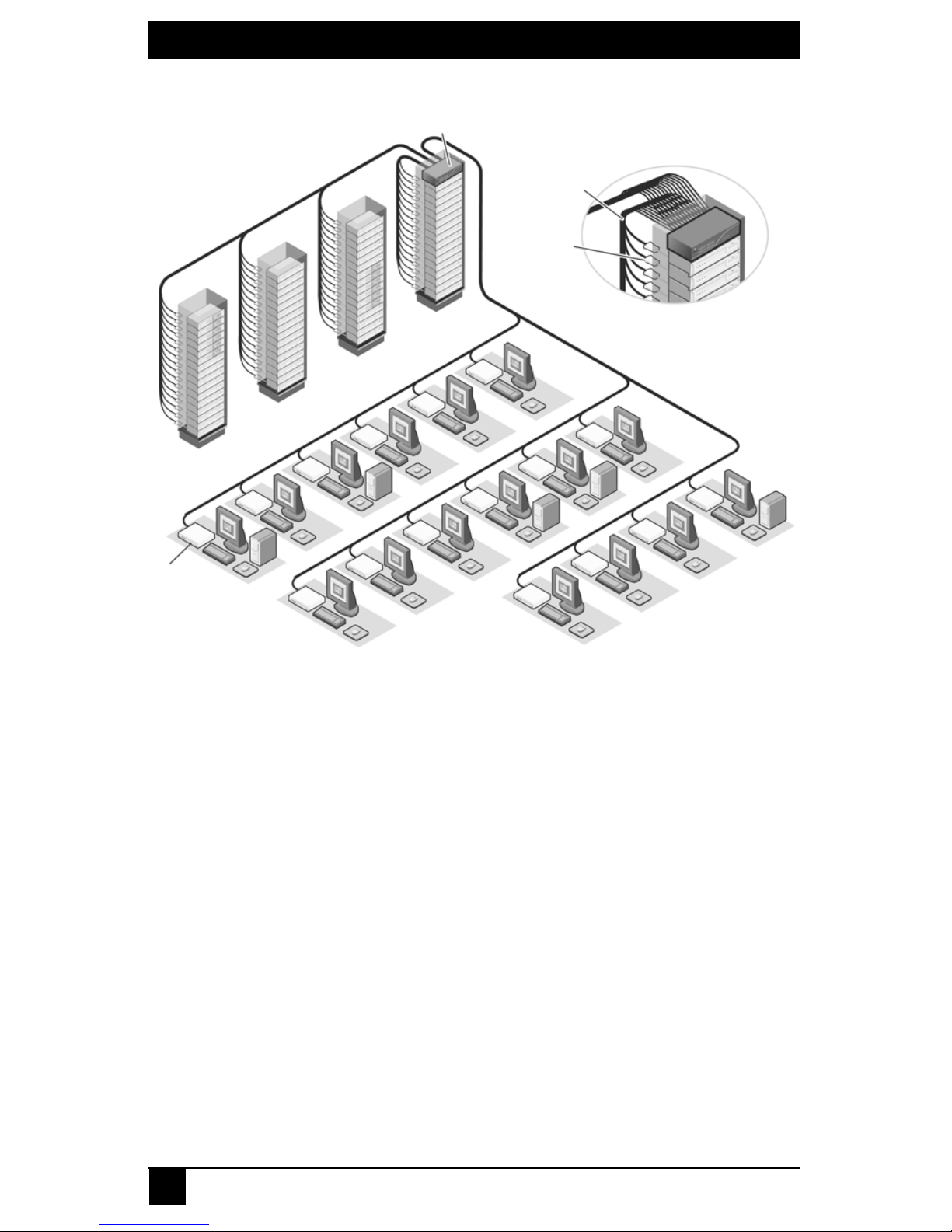
A typical Octet switching system configuration is illustrated in Figure 2-1.
SERVSWITCH™ OCTET INSTALLER/USER GUI DE
22
Figure 2-1. Typical Octet Switching System Configuration
The Octet switch
The Octet switch provides the framework for the Octet switching system and is available
in a variety of matrix sizes. Each Octet switch can be cascaded to create larger system
configurations. The Octet switch stor es a full database of user rights and server names and
communicates with the Octoware software through an IP (Internet Protocol) port.
The Octet user station
The Octet user station, the interface between the Octet switch and system users,
stores local (console) settings and provides connections for peripheral devices.
The user station also provides the OSD for target device selection and
administration.
The Octet switch Octet server access modules
The Octet server access module is the primary interface between an attached device
(KVM switch, serial device or PS/2, Sun or USB server) and the Octet switching system.
If the switch loses power, the target devices will continue to power the Octet server access
modules. This Keep Alive functionality ensures continued keyboard and mouse
operability and prevents data loss. Available in three types, Octet server access modules
also provide keyboard emulation, DDC (Digital Data Channel), and Octet switching
system support.
64 Servers
Octet Switch
Octet
User Station
UTP Cables
Octet
Server
Access
Module
16 Users

CHAPTER 2: PRODUCT OVERVIEW
23
• SAM module – a standard Octet server access module that connects a tar get device to
the switching system. SAM modules are available for PS/2, USB and Sun VGA or
13W3 interfaces.
• SAMDM module –a two-port Octet server access module that enables one server to
be shared between two Octet switches, increasing the number of users that can be
added to the switching system. The SAMDM module also enabl es the multimedia
feature (audio and serial data communication) when it is connected to a user station
that supports this feature. SAMDM modules are available as PS/2, USB and Sun
VGA interface modules.
• Serial SAM (serial) module – a DCE (Data Communication Equipment) device that
is the primary interface between a serial device and the Octet switching system. It
supports VT100 terminal emulation, break suppression and port history. See Chapter
6 beginning on page 89 for more information.
Octet server access modules are connected to the switching system with UTP cabling and
eliminate the need for additional cables or extra rack spaces. Each Octet server access
module has a factory-assigned unique number that identifies the attached target device
within the system.
UTP cables
You may use any combination of CAT 5, CAT 5e and CAT 6 cables in the Octet
switching system.
NOTE:
Throughout this manual, UTP refers to any CAT cable used by the Octet switching system.
2.4 Safety Precautions
To avoid potential video and/or keyboard problems when using Black Box products:
• If the building has 3-phase AC power, ensure that the server and monitor are on the
same phase. For best results, they should be on the same circuit.
To avoid potentially fatal shock hazard and possible damage to equipment, please observe
the following precautions:
• Do not use a 2-wire extension cord in any Black Box product configuration.
• Test AC outlets at the server and monitor for proper polarity and grounding.
• Use only with grounded outlets at both the server and monitor. When using a backup
Uninterruptible Power Supply (UPS), power the server, the monitor and the Octet
switch off the supply.
NOTE:
The AC inlet is the main disconnect.
DC installation safety considerations
As a safety precaution, install this product in an area with limited or controlled access. A
readily accessible disconnect device that is suitably approved and rated shall be
incorporated in the field wiring. Connect field wiring from earth ground to the screw
terminal marked with the ground symbol. Terminals will accommodate wiring from 26 to
12 AWG (up to 2.5 mm2 maximum cross section). Strip each wire, insert it in the square
opening in the terminal block and tighten the screw above it to a maximum of 70 ounceinches (0.5 Nm) using either a flat or Phillips-head screwdriver.

SERVSWITCH™ OCTET INSTALLER/USER GUI DE
24
Rack mount safety considerations
• Elevated Ambient Temperature: If installed in a closed rack assembly, the operation
temperature of the rack environment may be greater than room ambient. Use care not
to exceed the rated maximum ambient temperature of the unit.
• Reduced Air Flow: Installation of the equipment in a rack should be such that the
amount of airflow required for safe operation of the equipment is not compromised.
• Mechanical Loading: Mounting of the equipment in the rack should be such that a
hazardous condition is not ach ieved due to une ven mechanical loading.
• Circuit Overloading: Consideration should be given to the connection of the
equipment to the supply circuit and the effect that overloa ding of circuits might have
on overcurrent protection and supply wiring. Consider equipment nameplate ratings
for maximum current.
• Reliable Earthing: Reliable earthing of rack mounted equipment should be
maintained. Pay particular attention to supply connections other than direct
connections to the branch circuit (for example, use of power strips).

CHAPTER 3: INSTALLATION
25
3. Installation
3.1 Octet Switching Systems
Octet switching systems consist of an Octet switch or switches, user stations, target
devices, Octet server access modules and peripheral devices. See Figure 3.1 on page 26
and Figure 3-2 on page 27 for examples of switching system configurations.
3.2 Getting Started
Before installing your Octet switching system, make sure you have access to the
following items:
• The Octet switch and all of the items supplied with it. These items may include a
power cord, rack mounting brackets, a null modem cable, installation CDs and
help materials.
•
At least one user station for connecting to the Octet switch.
• UTP cables for each target device and user station you plan to attach to the
switching system.
• One SAM or SAMDM module for each server and one Serial SAM module for each
serial device.
• Octoware software, available by free download at www.blackbox.com or on the
installation CD included with the Octet switch.
SERVSWITCH™ OCTET INSTALLER/USER GUI DE
26
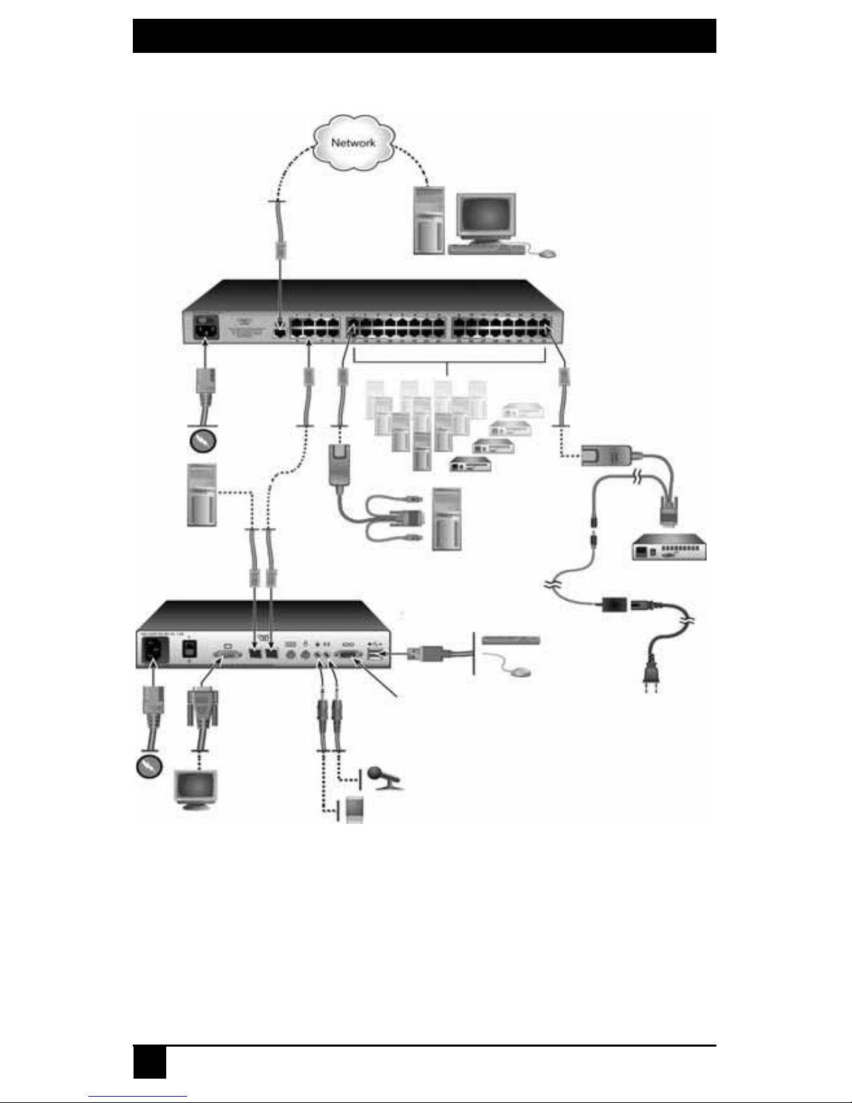
Figure 3.1 illustrates one possible switching sy stem configuration using SAM and
Serial SAM modules.
Figure 3.1: Octet Switching System Configuration with SAMs and Serial SAMs
Octet Switch (KV1701A/E Switch Shown)
Octet User Station
(KV1713 User Station Shown)
Serial SAM
Local PC
SAM
(PS/2 Shown)
Server with
Octoware Software
USB Keyboard
and Mouse
Serial Device
Stereo Speakers
and Microphone
Monitor
Target Devices
Serial Port

CHAPTER 3: INSTALLATION
27
Figure 3-2 illustrates another possible switching system configuration using SAMDM
modules, specialized Octet server access modules with dual port connectivity and audio
and serial connections.
Figure 3-2. Octet Switching System Configuration with SAMDMs
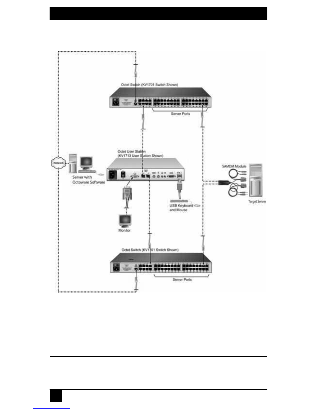
Figure 3-3 illustrates a switching system configuration where two Octet switches are
connected to a single user station, and target servers connected to both switches using
Octet Switch (KV1701A/E Switch Shown)
SAMDM
(PS/2 Shown)
Serial Port
Local Server
USB Keyboard
and Mouse
Monitor
Stereo Speakers
and Microphone
Server with
Octoware Software
Octet User Station
(KV1713 User Station Shown)
Target Devices
SERVSWITCH™ OCTET INSTALLER/USER GUI DE
28
SAMDM modules. By utilizing this connection method, you may benefit from switch
redundancy in the event of a single switch failover.
Figure 3-3. Octet Switching System Configuration with Redundancy
3.3 Rack Mounting an Octet Switch
A rack mounting kit is supplied with each Octet switch. You may either place the Octet
switch on the rack shelf or mount the switch directly into an Electronic Industries Alliance
(EIA) standard rack.
CAUTION: Rack Loading -
Overloading or uneven loading of racks may result in shelf or rack failure, causing damage to equipment
and possible personal injury. Stabilize racks in a permanent location before loading begins. Mount
 Loading...