

Page 1
Page 2

SERVSWITCH™ FAMILY
Welcome to the ServSwitch™ Family!
Thank you for purchasing a BLACK BOX® Octopus! We appreciate your business,
and we think you’ll appreciate the many ways that your new Octopus will save you
money, time, and effort.
That’s because our ServSwitch family is all about breaking away from the traditional,
expensive model of computer management. You know, the one-size-fits-all-even-if-it-
doesn’t model that says, “One computer gets one user station, no more, no less.” Why
not a single user station (monitor, keyboard, and mouse) for multiple computers—even
computers of different platforms? Why not a pair of user stations, each of which can
control multiple computers? Why not multiple user stations for the same computer?
With our ServSwitch products, there’s no reason why not. We carry a broad line of
robust solutions for all these applications. Do you have just two PCs, and need an
economical alternative to keeping two monitors, keyboards, and mice on your desk?
Or do you need to share dozens of computers, including a mix of IBM
RS/6000
®
, Apple® Macintosh®, Sun Microsystems®, and SGI™ compatibles among
multiple users with different access levels? Does your switch have to sit solidly on a
worktable and use regular everyday cables? Or does it have to be mounted in an
equipment rack and use convenient many-to-one cables? No matter how large or
small your setup is, no matter how simple or how complex, we’re confident we have
a ServSwitch system that’s just right for you.
®
PC,
The ServSwitch™ family from BLACK BOX—the one-stop answer for all your
KVM switching needs!
*
This manual will tell you all about your new ServSwitch Octopus, including how to
install, operate, and troubleshoot it. For an introduction to the ServSwitch Octopus,
see Chapter 2. The ServSwitch Octopus product codes covered in this manual are:
KV1701E KV1702E KV1710E
This manual also includes information about the ServSwitch Octopus software and
the Server Access Modules (SAM), which have their own manuals or installation
guides:
KV1720A KV1721A KV1722A
1
Page 3

SERVSWITCH™ OCTOPUS INSTALLER/USER GUIDE
FEDERAL COMMUNICATIONS COMMISSION AND
INDUSTRY CANADA
RADIO-FREQUENCY INTERFERENCE STATEMENTS
This equipment generates, uses, and can radiate radio-frequency energy and if not
installed and used properly, that is, in strict accordance with the manufacturer’s
instructions, may cause interference to radio communication. It has been tested and
found to comply with the limits for a Class A computing device in accordance with
the specifications in Subpart B of Part 15 of FCC rules, which are designed to
provide reasonable protection against such interference when the equipment is
operated in a commercial environment. Operation of this equipment in a residential
area is likely to cause interference, in which case the user at his own expense will be
required to take whatever measures may be necessary to correct the interference.
Changes or modifications not expressly approved by the party responsible for
compliance could void the user’s authority to operate the equipment.
This digital apparatus does not exceed the Class A limits for radio noise emission from
digital apparatus set out in the Radio Interference Regulation of Industry Canada.
Le présent appareil numérique n’émet pas de bruits radioélectriques dépassant les
limites applicables aux appareils numériques de la classe A prescrites dans le
Règlement sur le brouillage radioélectrique publié par Industrie Canada.
EUROPEAN UNION DECLARATION OF CONFORMITY
This equipment has been tested and found to comply with the limits for a Class A
computing device in accordance with the specifications in the European standard
EN55022. These limits are designed to provide reasonable protection against
harmful interference. This equipment generates, uses and can radiate radio-
frequency energy, and if not installed and used in accordance with the instructions,
might cause harmful interference to radio or television reception.
However, there is no guarantee that harmful interference will not occur in a
particular installation. If this equipment does cause interference to radio or television
reception, which can be determined by turning the equipment on and off, you can
correct the interference with one or more of the following measures:
a. Reorient or relocate the receiving antenna.
b. Increase the separation between the equipment and the receiver.
c. Connect the equipment to an outlet on a circuit different from that to which the
receiver is connected.
d. Consult the supplier or an experienced radio/TV technician for help.
2
Page 4

COMPLIANCE STATEMENTS
Shielded cables must be used with this equipment to maintain compliance with radio
frequency energy emission regulations and ensure a suitably high level of immunity
to electromagnetic disturbances. This equipment has also been found to comply with
European standards EN50082 and EN60950.
Japanese Compliance Statement
Other Agency Approvals
USA (UL, FCC)
Canada (cUL, ICES-003)
European Union (CE)
TRADEMARKS USED IN THIS MANUAL
®
BLACK BOX® and the logo are registered trademarks, and ServSwitch,
ServSelect, and ServSelect IP are trademarks of BLACK BOX Corporation.
Apple, Mac, and Macintosh are registered trademarks of Apple Computer, Inc.
IBM, PS/2, and RS/6000 are registered trademarks of International Business
Machines Corporation.
Microsoft, HyperTerminal, Windows, Windows NT, and Windows XP are
trademarks or registered trademarks of Microsoft Corporation in the United States
and/or other countries.
Sun and Sun Microsystems are registered trademarks of Sun Microsystems, Inc. in
the United States and other countries.
UL is a registered trademark of Underwriters Laboratories Inc.
Any other trademarks mentioned in this manual are acknowledged to be the property
of the trademark owners.
3
Page 5

SERVSWITCH™ OCTOPUS INSTALLER/USER GUIDE
Normas Oficiales Mexicanas (NOM)
Electrical Safety Statement
INSTRUCCIONES DE SEGURIDAD
1. Todas las instrucciones de seguridad y operación deberán ser leídas antes de
que el aparato eléctrico sea operado.
2. Las instrucciones de seguridad y operación deberán ser guardadas para
referencia futura.
3. Todas las advertencias en el aparato eléctrico y en sus instrucciones de
operación deben ser respetadas.
4. Todas las instrucciones de operación y uso deben ser seguidas.
5. El aparato eléctrico no deberá ser usado cerca del agua—por ejemplo, cerca de
la tina de baño, lavabo, sótano mojado o cerca de una alberca, etc.
6. El aparato eléctrico debe ser usado únicamente con carritos o pedestales que
sean recomendados por el fabricante.
7. El aparato eléctrico debe ser montado a la pared o al techo sólo como sea
recomendado por el fabricante.
8. Servicio—El usuario no debe intentar dar servicio al equipo eléctrico más allá a
lo descrito en las instrucciones de operación. Todo otro servicio deberá ser
referido a personal de servicio califi cado.
9. El aparato eléctrico debe ser situado de tal manera que su posición no interfi era
su uso. La colocación del aparato eléctrico sobre una cama, sofá, alfombra o
superfi cie similar puede bloquea la ventilación, no se debe colocar en libreros o
gabinetes que impidan el fl ujo de aire por los orifi cios de ventilación.
10. El equipo eléctrico deber ser situado fuera del alcance de fuentes de calor como
radiadores, registros de calor, estufas u otros aparatos (incluyendo
amplifi cadores) que producen calor.
11. El aparato eléctrico deberá ser connectado a una fuente de poder sólo del tipo
descrito en el instructivo de operación, o como se indique en el aparato.
12. Precaución debe ser tomada de tal manera que la tierra fi sica y la polarización
del equipo no sea eliminada.
13. Los cables de la fuente de poder deben ser guiados de tal manera que no sean
pisados ni pellizcados por objetos colocados sobre o contra ellos, poniendo
particular atención a los contactos y receptáculos donde salen del aparato.
14. El equipo eléctrico debe ser limpiado únicamente de acuerdo a las
recomendaciones del fabricante.
15. En caso de existir, una antena externa deberá ser localizada lejos de las lineas
de energia.
16. El cable de corriente deberá ser desconectado del cuando el equipo no sea
usado por un largo periodo de tiempo.
4
Page 6

NOM STATEMENT
17. Cuidado debe ser tomado de tal manera que objectos liquidos no sean
derramados sobre la cubierta u orifi cios de ventilación.
18. Servicio por personal califi cado deberá ser provisto cuando:
A: El cable de poder o el contacto ha sido dañado; u
B: Objectos han caído o líquido ha sido derramado dentro del aparato; o
C: El aparato ha sido expuesto a la lluvia; o
D: El aparato parece no operar normalmente o muestra un cambio en su
desempeño; o
E: El aparato ha sido tirado o su cubierta ha sido dañada.
5
Page 7

Contents
1. Specifications . . . . . . . . . . . . . . . . . . . . . . . . . . . . . . . . . . . . . . . . . . . . .8
2. Introduction . . . . . . . . . . . . . . . . . . . . . . . . . . . . . . . . . . . . . . . . . . . . . .12
2.1 Features and Benefits . . . . . . . . . . . . . . . . . . . . . . . . . . . . . . . . . . . . . . . . . . . . .12
2.2 Component Overview . . . . . . . . . . . . . . . . . . . . . . . . . . . . . . . . . . . . . . . . . . . . .13
2.3 Safety Precautions . . . . . . . . . . . . . . . . . . . . . . . . . . . . . . . . . . . . . . . . . . . . . . . .15
3. Installation . . . . . . . . . . . . . . . . . . . . . . . . . . . . . . . . . . . . . . . . . . . . . . .16
3.1 Getting Started . . . . . . . . . . . . . . . . . . . . . . . . . . . . . . . . . . . . . . . . . . . . . . . . . .16
3.2 Installing the Octopus System . . . . . . . . . . . . . . . . . . . . . . . . . . . . . . . . . . . . . .17
3.3 Installing a Tiered Octopus System . . . . . . . . . . . . . . . . . . . . . . . . . . . . . . . . . .22
3.4 Configuring the Octopus Database . . . . . . . . . . . . . . . . . . . . . . . . . . . . . . . . . . .24
3.5 FLASH Upgrading the Octopus System . . . . . . . . . . . . . . . . . . . . . . . . . . . . . .24
4. Basic Operations . . . . . . . . . . . . . . . . . . . . . . . . . . . . . . . . . . . . . . . . . .25
4.1 Power Up and LEDs . . . . . . . . . . . . . . . . . . . . . . . . . . . . . . . . . . . . . . . . . . . . . .25
4.2 User Operations . . . . . . . . . . . . . . . . . . . . . . . . . . . . . . . . . . . . . . . . . . . . . . . . .26
4.3 Octopus OSD Overview . . . . . . . . . . . . . . . . . . . . . . . . . . . . . . . . . . . . . . . . . . .27
4.4 Selecting Servers . . . . . . . . . . . . . . . . . . . . . . . . . . . . . . . . . . . . . . . . . . . . . . . . .29
4.5 Keyboard Translation . . . . . . . . . . . . . . . . . . . . . . . . . . . . . . . . . . . . . . . . . . . . .30
5. Advanced Operations . . . . . . . . . . . . . . . . . . . . . . . . . . . . . . . . . . . . . .32
5.1 User Maintenance . . . . . . . . . . . . . . . . . . . . . . . . . . . . . . . . . . . . . . . . . . . . . . . .32
5.2 Server Maintenance . . . . . . . . . . . . . . . . . . . . . . . . . . . . . . . . . . . . . . . . . . . . . .34
5.3 Console Maintenance . . . . . . . . . . . . . . . . . . . . . . . . . . . . . . . . . . . . . . . . . . . . .35
6. Terminal Operations . . . . . . . . . . . . . . . . . . . . . . . . . . . . . . . . . . . . . . .38
6.1 Accessing the Terminal Menu . . . . . . . . . . . . . . . . . . . . . . . . . . . . . . . . . . . . . .38
7. Troubleshooting . . . . . . . . . . . . . . . . . . . . . . . . . . . . . . . . . . . . . . . . . . 40
7.1 Calling Black Box . . . . . . . . . . . . . . . . . . . . . . . . . . . . . . . . . . . . . . . . . . . . . . . .40
7.2 Shipping and Packaging . . . . . . . . . . . . . . . . . . . . . . . . . . . . . . . . . . . . . . . . . . .40
7
Page 8

SERVSWITCH™ OCTOPUS INSTALLER/USER GUIDE
1. Specifications
During the course of this product’s lifetime, modifications might be made to its
hardware or firmware that could cause these specifications to change without notice.
Octopus 832 Product Specifi cations
Agency Approvals
EN55022 Class A, EN55024, EN61000-3-2, EN61000-3-3,
EN60950, FCC15 Class A, CSA C22.2 No. 60950, UL60950
third edition, VCCI Class A
Mechanical
Width: 17” (432 mm)
Depth: 11” (281 mm)
Weight: 8 lb (3.7 kg)
Environmental/Power
Power consumption: 75 W
AC input power: max 75 W
Heat dissipation: 270 Kj
Humidity: 10-95% non-condensing
Operating temperature: Ø° C-50° C
Storage temperature: -20° C-60° C
Operating voltage: 100-240 Vac
Power frequency: 50-60 Hz
Ports
Network number: 1, RJ45, Ethernet, 10 Base-T, 100 Base-T
Server ports: 32, RJ45 Octopus interconnect
User ports: 8, RJ45 Octopus interconnect
Terminal port: 1, DB9 male, RS232 serial
Height: 1U
8
Page 9

CHAPTER 1: SPECIFICATIONS
Octopus 1664 Product Specifi cations
Agency Approvals
EN55022 Class A, EN55024, EN61000-3-2, EN61000-
3-3, EN60950, FCC15 Class A, CSA C22.2 No. 60950,
UL60950 third edition, VCCI Class A
Mechanical
Height: 2 U
Width: 17” (432 mm)
Depth: 11” (281 mm)
Weight: 16 lb (7.27 kg)
Environmental/Power
Power consumption: 150 W
AC input power: max 150 W
Heat dissipation: 610 Kj
Humidity: 10-95% non-condensing
Operating temperature: Ø° C-50°C
Storage temperature: -20° C-60° C
Operating voltage: 100-240 Vac
Power frequency: 50-60 Hz
Ports
Network number: 1, RJ45, ethernet, 10 Base-T, 100 Base-T
Server ports: 64, RJ45 Octopus interconnect
User ports: 16, RJ45 Octopus interconnect
Terminal port: 1, DB9 male, RS232 serial
9
Page 10

SERVSWITCH™ OCTOPUS INSTALLER/USER GUIDE
Octopus 1710 Product Specifi cations
Agency Approvals
EN55022 Class A, EN55024, EN61000-3-2, EN61000-
3-3, EN60950, FCC15 Class A, CSA C22.2 No. 60950,
UL60950 third edition, VCCI Class A
Mechanical
Height: 1U
Width: 10.98" (27.9 cm)
Depth: 11.5" (29.2 cm)
Weight: 4.41 lb (2 kg)
Environmental/Power
Power consumption: 25 W
AC input power: max 25 W
Heat dissipation: 90 Kj
AC input current rating: 1A
Humidity: 10-95% non-condensing
Operating temperature: Ø° C-50° C
Storage temperature: -20° C-60° C
Operating voltage: 100-240 Vac
Power frequency: 50-60 Hz
Ports
Input Ports: 1, RJ45 Octopus interconnect
Output ports: 1 6-pin miniDIN, PS/2 keyboard, 1 6-pin
miniDIN, PS/2 mouse; 1 8-pin miniDIN, Sun keyboard and
mouse, 1 15HDD female, VGA video
Supported Hardware
Peripherals: PS/2 keyboard and mouse, Sun keyboard and
mouse
Video resolution: 1024 x 768 with 1,000 feet of UTP from
server to user, 1600 x 1200 with 100 feet of UTP from
server to user
Sync types: Separate horizontal and vertical; composite
sync on Sun monitors
10
Page 11

CHAPTER 1: SPECIFICATIONS
Octopus SAM (PS/2, USB, Sun HD15, Sun 13WSN) Product Specifi cations
Agency Approvals
EN55022 Class A, FCC15 Class A
Mechanical
Height: .83" (2.11 cm)
Width: 2.43" (6.17 cm)
Depth: 4.02" (10.21 cm)
Weight: .29 lb (.13 kg)
Environmental/Power
Power consumption: 130 mA
Humidity: 10-95% non-condensing
Operating temperature: 10° C-50° C
Storage temperature: -20° C-60° C
Power supply: 5 Vdc
Agency Ports
Input
ports for SAM-PS/ 2: 1 6-pin miniDIN, PS/2
keyboard, 1 6-pin miniDIN, PS/2 mouse; 1 15HDD
male, VGA Video, 1 RJ45 Octopus interconnect
Input
ports for SAM-VSN: 1 8-pin miniDIN, Sun keyboard
and mouse, 1 15HDD male VGA video
Input
ports for SAM-WSN: 1 8-pin miniDIN, Sun keyboard
and mouse, 1 13W3 male video
Input
ports for SAM-USB: 1 USB keyboard and mouse
(supports Intel, Sun, Macintosh), 1 15HDD male VGA video
Output ports: 1 RJ45 Octopus interconnect
Server Ports
Type: PS/2 keyboard and mouse, VGA video
Connectors: 2 6-pin miniDIN, 1 15HDD
Sync types: Separate horizontal and vertical, Sync on
Green (as used on SGI and HP9000); composite sync on
Sun monitors
Plug and Play: DDC2B
11
Page 12

SERVSWITCH™ OCTOPUS INSTALLER/USER GUIDE
2. Introduction
2.1 Features and Benefits
The BLACK BOX® ServSwitch™ Octopus Series of products allows multiple users
within the switching system to access and operate PC-compatible, USB and Sun
servers at the same time. A basic Octopus system consists of users and servers that
are all connected to one or more Octopus units. Any user in the system can access
any attached server by simply switching to it through an Octopus unit.
Multiplatform
The Octopus Series features multiplatform capabilities, enabling your switching
system to simultaneously support any combination of PC, USB or Sun servers. Switch
easily across platforms with a PS/2 or Sun keyboard and mouse. Operated through the
Octopus system, a PC keyboard and mouse can operate a Sun server as easily as a Sun
keyboard and mouse will operate an attached PC.
Multiuser
The Octopus Series allows “matrix switching,” enabling multiple users to have
simultaneous access to different servers in the system. For example, an Octopus
system with four users accessing four different servers is a 4 x 4 matrix. Eight users
accessing 10 different servers would be an 8 x 10 system.
Sharing
If two or more users need access to the same server, they can share access through
the Octopus Series units. Sharing enables multiple users to switch to the same server
at the same time. Everyone can see the server’s video, but only one user can enter
data at any given moment.
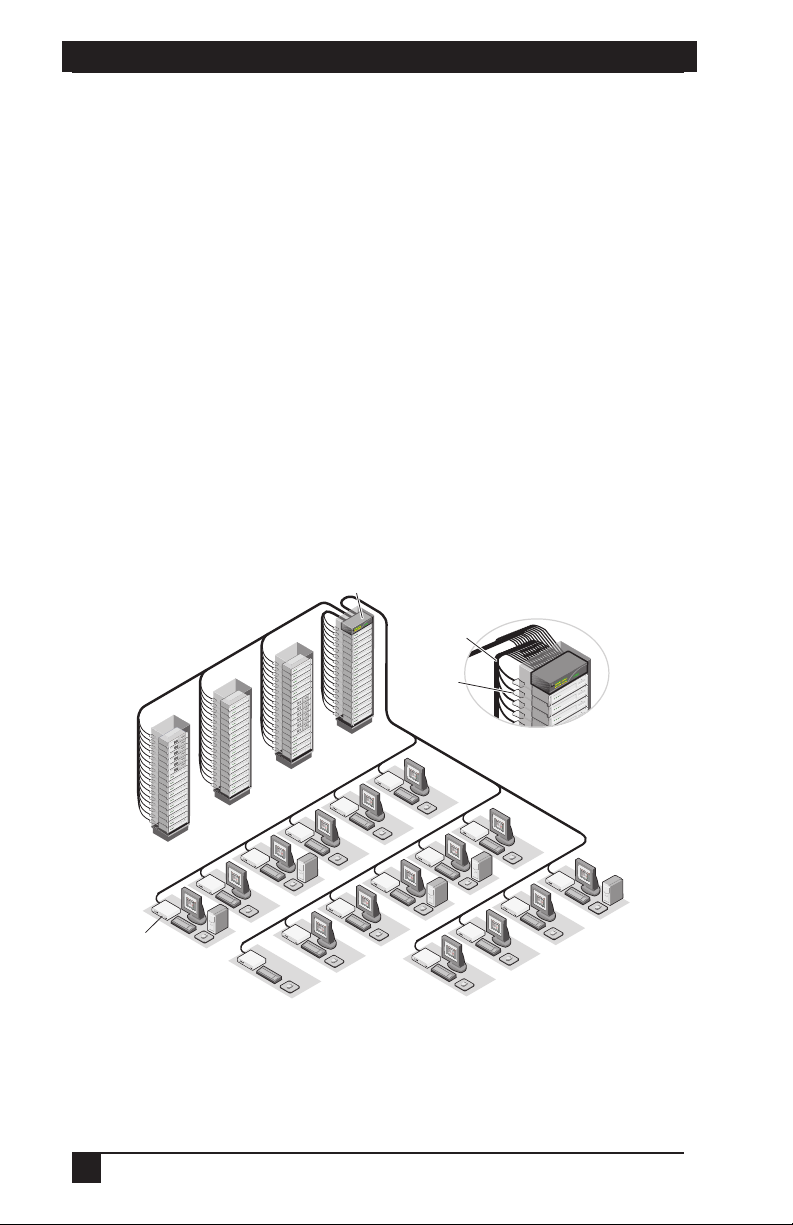
Expansion capability
If your total number of servers is greater than 32 or 64, you can connect multiple
Octopus Series units together to give dozens of users control of hundreds of servers
from one set of peripherals. For additional flexibility, you can attach other BLACK
BOX keyboard, video and mouse (KVM) switches to the Octopus as well.
Octopus OSD
Octopus switches are equipped with the Octopus OSD (On-Screen Display). The
Octopus OSD allows you to use your keyboard or mouse to select any attached
system computer. The Octopus OSD supports multilevel security with password
protection, allowing you to control how much access users have to each server in
your data center.
12
Page 13

CHAPTER 2: INTRODUCTION
For additional security, Octopus can be configured to log out after a user-defined
period of inactivity. When the time-out is reached, the current channel is deselected
and the screen goes blank. Users must log in again to access system servers.
The Octoware utility
Octoware is the standalone administration utility supplied with each Octopus that
allows you to assign names to attached servers and administer naming and access
information for attached users. Octoware can be used to configure Octopus
installations remotely, eliminating the need to configure each unit separately. In
addition, Octoware supports the ability to monitor and report on all system and
switching events and activities.
2.2 Component Overview
A BLACK BOX Octopus system consists of four main components:
• One or more Octopus units
• Octopus user station(s)
• Octopus Server Access Module (SAM)
• UTP cables
Octopus unit and Octopus matrix switch are used interchangeably in this user guide.
The quantity and type of components you receive depend on the specific
configuration you order.
NOTE:
The Octopus unit
The Octopus matrix switch (Octopus 832 or Octopus 1664), provides the framework
for the Octopus system. The Octopus 832 allows eight users to connect to up to 32
computers and occupies only 1U of rack space. The Octopus 1664 allows 16 users to
connect to up to 64 computers and occupies 2U of rack space. Both units can be
tiered to connect larger system configurations. The Octopus 832 and the Octopus
1664 store a full database of user rights and computer names and communicate with
the Octoware system management utility via an Internet Protocol (IP) port.
The Octopus user station
The Octopus 1710 user station is the interface between the Octopus switch and
system users. It provides the Octopus interface for server selection and
administration, as well as full compensation for video degradation. The Octopus user
station is housed in a desktop mounting unit that may also act as a monitor stand.
13
Page 14
SERVSWITCH™ OCTOPUS INSTALLER/USER GUIDE
The Octopus SAM
The Octopus SAM provides the primary interface between an attached device (KVM
switch or PS/2, Sun or USB server) and the Octopus system. It provides all Keep
Alive, keyboard emulation, DDC (Digital Data Channel) and Octopus support in a
server-powered convenient cable format. This eliminates the need for extra rack
space, power outlets or additional cables. For ease of installation, each Octopus
SAM has a factory-assigned unique number that identifies the attached server within
the system. The connection between the Octopus system and the Octopus SAM is
via industry standard UTP cabling.
UTP cables
The Octopus system uses video technologies that compensate for the losses that
occur in all UTP cables. These technologies make the Octopus compatible with most
UTP cable types and support Octopus use in environments where there are
combinations of UTP cable types and patch panels. The Octopus will function
correctly with any combination of CAT5, CAT5e and CAT6 cables. Throughout this
manual, the generic term UTP refers to any CAT cable used by the Octopus system.
Octopus 1664 Switch
64 Servers
Octopus 1710
User Station
16 Users
Figure 2-1. Typical O ctopus Configuration
14
UTP Cables
SAM
Page 15

CHAPTER 2: INTRODUCTION
2.3 Safety Precautions
To avoid potential video and/or keyboard problems when using these products:
• If the building has 3-phase AC power, ensure that the computer and monitor are
on the same phase. For best results, they should be on the same circuit.
• Use only BLACK BOX-recommended cable to connect computers and
KVM switches.
To avoid potentially fatal shock hazard and possible damage to equipment, please
observe the following precautions:
• Do not use a 2-wire extension cord in any BLACK BOX product confi guration.
• Test AC outlets at the computer and monitor for proper polarity and grounding.
• Use only with grounded outlets at both the computer and monitor. When using
a backup Uninterruptible Power Supply (UPS), power the computer, the monitor and the appliance off the supply.
The AC inlet is the main disconnect.
NOTE:
Rackmount safety considerations
• Elevated Ambient Temperature: If the equipment is installed in a closed rack
assembly, the operation temperature of the rack environment may be greater than
room ambient. Use care not to exceed the rated maximum ambient temperature of
the equipment.
• Reduced Air Flow: Installation of the equipment in a rack should be such that the
amount of airfl ow required for safe operation of the equipment is not compromised.
• Mechanical Loading: Mounting of the equipment in the rack should be such
that a hazardous condition is not achieved due to uneven mechanical loading.
• Circuit Overloading: Consideration should be given to the connection of the
equipment to the supply circuit and the effect that overloading of circuits might
have on overcurrent protection and supply wiring. Consider equipment nameplate ratings for maximum current.
• Reliable Earthing: Reliable earthing of rackmounted equipment should be
maintained. Pay particular attention to supply connections other than direct
connections to the branch circuit (for example, use of power strips).
15
Page 16

SERVSWITCH™ OCTOPUS INSTALLER/USER GUIDE
3. Installation
The Octopus system uses standard UTP cables to transmit KVM information
between users and attached servers.
3.1 Getting Started
Before installing your Octopus system, refer to the following lists to ensure that you
have all the items that shipped with the Octopus system as well as other items neces-
sary for proper installation.
Supplied with the Octopus system
• Octopus unit (Octopus 832 or Octopus 1664)
• An EU power cord
• Rackmounting brackets
• A null modem cable
• Octopus Series Installer/User Guide
• Octoware software and user guide on CD
• Octopus Series Quick Install Guide
Supplied with the Octopus user station
• Octopus 1710 user station
• An EU power cord
• Octopus Series Quick Install Guide
Supplied with the Octopus SAM
• Octopus SAM (PS/2, USB, Sun HD15 or Sun 13W3)
• Octopus SAM Quick Install Guide
Needed for installation
• UTP cables for each server and user station you plan to attach to the Octopus system
• One Octopus 1710 user station unit per user station
• One Octopus SAM per server
Optionally you may need:
• Octoware software available on the included CD and through download from
Black Box
16
Page 17

CHAPTER 3: INSTALLATION
3.2 Installing the Octopus System
Figure 3-1 illustrates one possible configuration for your Octopus unit. Follow
the detailed set of procedures following Figure 3-1 to install the Octopus system.
Octopus 832
SAM
Octopus 1710
User Station
Figure 3-1. Basic ServSwitch Octopus Configuration
CAUTION: Power Considerations
To r ed uc e t he risk of electric shock or damage to your equipment-
- Do not disable the power cord grounding plug. The grounding plug is an impor tant safet y feature.
- Plug the power cord into a grounded (earthed) outlet that is easily accessible at all times.
- Disconnect the power from the unit by unplugging the power cord from either the electrical
outlet or the unit.
17
Page 18

SERVSWITCH™ OCTOPUS INSTALLER/USER GUIDE
Installing the Octopus unit
The Octopus unit is the central hub of your Octopus system. All users and computers
are connected through it.
Figure 3-2. Octopus 832 Unit
33 34 35 36 37 38 39 40 41 42 43 44 45 46 47 48
49 50 51 52 53 54 55 56 57 58 59 60 61 62 63 64
910111213141516
Figure 3-3. Octopus 1664 Unit
Rackmounting your Octopus unit
You can either place your Octopus unit on your rack shelf or rackmount your unit
into an EIA standard rack.
A rackmounting kit is supplied with each Octopus. Before installing the switch and
other components in the rack, stabilize the rack in a permanent location. Start rack
mounting your equipment at the bottom of the rack, then work to the top. Avoid
uneven loading or overloading of the rack.
- Do not disable the power cord grounding plug. The grounding plug is an important safety feature.
To r ed uc e t he risk of electric shock or damage to your equipment-
- Plug the power cord into a grounded (earthed) outlet that is easily accessible at all times.
- Disconnect the power from the unit by unplugging the power cord from either the electrical
Connect only to the power source specifi ed on the unit. When multiple electrical components
are installed in a rack, ensure that the total component power ratings do not exceed circuit
capabilities. Overloaded power sources and extension cords present fi re and shock hazards.
CAUTION: Rack Loading
outlet or the unit.
CAUTION: Power Considerations
18
Page 19

CHAPTER 3: INSTALLATION
Figure 3-4. Octopus 832 Rackmounting Diagram
Figure 3-5. Octopus 1664 Rackmounting Diagram
To install the rack mounting bracket:
1. Remove the two side screws closest to the front from each side of your
Octopus unit.
2. Line up the holes in the brackets with the holes on the sides of the Octopus unit.
3. Using the screws supplied with the rackmounting bracket, thread one through
each of the holes in the sides of the rackmount brackets and into the Octopus
unit. Tighten them securely.
4. Install the Octopus unit into your rack using the approved method of your
rack manufacturer.
19
Page 20

SERVSWITCH™ OCTOPUS INSTALLER/USER GUIDE
To install a new single Octopus unit:
1. Plug the power cord into the back of the Octopus unit and then into an
appropriate power source.
2. Connect a terminal or PC running terminal emulation software (such as
HyperTerminal) to the terminal port on the front panel of the Octopus using the
supplied null modem cable. The terminal should be set to 9600 baud, 8 bits, 1
stop bit, no parity and no fl ow control.
3. When the power is switched on, the Power indicator on the front of the unit will
remain orange for approximately 30 seconds while performing a self-test, and
then change to green. This indicates a healthy condition.
4. Next, follow these instructions to set up the Terminal Applications menu. Refer
to Chapter 6 for more details.
a. You will be prompted to enter a username. The fi rst time you access the
switch, enter the username
to the Octopus Console menu, you can confi gure a password should you
wish to do so.
b. Once you have logged in to the Octopus, you will see the Octopus Console
menu with four options. Select option 1, Network Confi guration. This will
activate the Network Confi guration menu.
c. From the Network Confi guration menu, select option 1 to set the IP address.
d. Select options 2 and 3 to set your netmask and default gateway respectively.
e. After you have entered these settings, type
Console menu.
f. If all Octopus units in your installation are part of the same Octopus con-
fi guration, you may leave the confi guration ID set to
more than one Octopus confi guration within your subnet, you will need
designate the group to which this Octopus belongs. To do this, select option
2 to enter the confi guration ID for your Octopus unit. A confi guration ID
designates an Octopus unit as part of a unique installation. When change
commands are issued via Octoware, only units with the same confi gura-
tion ID as the Octoware will be affected. Refer to System Management in
Chapter 6 for more information on setting confi guration IDs.
g. After entering a confi guration ID, enter
h. Finally, select option 3 and follow the prompts to password protect your
Octopus terminal settings.
i. Press
Ø to exit the Octopus Console menu.
admin and press Enter. Once you have access
Ø to return to the Octopus
Ø. If you are running
to
Ø to return to the main menu.
To make a LAN connection:
Using a UTP cable, connect the Network port on the back of the Octopus to your LAN.
Both Octoware and Octopus must be on the same subnet in class A, B or C to function properly.
NOTE:
20
Page 21

CHAPTER 3: INSTALLATION
Connecting servers to the Octopus
Once the Octopus unit is installed, you may begin attaching servers and other
BLACK BOX KVM switches to it. Both are connected to the Octopus through the
use of the SAMs. For information on connecting other BLACK BOX KVM switches
to the Octopus, see Installing a Tiered Octopus System later in this chapter.
Network Port User Ports
Figure 3-6. Octopus 832 Rear Panel
Terminal Port
Network Port
Figure 3-7. Octopus 1664 Rear Panel
User Ports
Server Ports
Server Ports
To connect servers to the Octopus system:
1. Locate the SAM appropriate to the server you wish to attach.
2. Plug the SAM keyboard, monitor and mouse connectors into the appropriate
ports on the back of the selected server.
3. Connect one end of a UTP cable into the RJ45 port on your SAM. Route the
cable to your Octopus unit and connect the other end to one of the available
RJ45 server ports. Check the unique identifi er (UID) on the back of the SAM
and log it for future use. When the attached computer is powered and a valid
UTP connection is made to an Octopus switch, the green light on the SAM
will illuminate.
Repeat this procedure for every server that will be attached to your Octopus system.
21
Page 22

SERVSWITCH™ OCTOPUS INSTALLER/USER GUIDE
Connecting users to the Octopus
Once all servers are connected, you may begin to connect users. Users are connected
to the Octopus system through the Octopus 1710 user station.
AC Power Connection to
Octopus Unit
Figure 3-8. Octopus 1710 User Station
KVM Access
To connect users to the Octopus system:
1. Place the Octopus 1710 user station at the desired user station. The Octopus
1710 is desig ned to bear the weight of a monitor and can be used as a monitor stand.
2. Plug your keyboard, monitor and mouse cables into the appropriate ports on the
back of the Octopus 1710 user station.
3. Connect one end of a UTP cable into the RJ45 port on the Octopus 1710 user
station. Route the cable to your Octopus unit and connect the other end to one
of the available RJ45 user ports.
4. Locate the power cord that shipped with the Octopus 1710 user station. Plug it
into the power socket on the rear of the unit. Plug the other end into an
appropriate AC wall outlet.
Power d own the Octopus unit before servicing. Always disconnect the power cord from the
NOTE:
wall outlet.
3.3 Installing a Tiered Octopus System
Multiple KVM switches can be connected to provide access to additional servers.
Figure 3-9 illustrates one possible configuration for your Octopus. Follow the
detailed set of procedures following Figure 3-9 to successfully install your tiered
Octopus system.
22
Page 23

CHAPTER 3: INSTALLATION
Local Users
Octopus 1664
Octopus 1710
User Station
Octopus 832
Servers Servers Servers Servers
Figure 3-9. Tiered Octopus System
Octopus 832
Octopus 832
Servers Servers
Octopus 832
Octopus 832
Octopus 832
To install a tiered Octopus system:
1. Position the Octopus units that will be connected and select a unit to be the
primary hub.
2. Connect one end of a UTP cable into a server port on the primary hub. Route
the cable to the tiered Octopus unit and connect it to an available user port.
Continue this process until all eight user ports on the tiered Octopus unit have
been connected.
3. You may now connect servers to the tiered Octopus units. You may also use
these tiered Octopus units to tier another layer of Octopus units. Up to three
levels, or tiers, of Octopus units can be connected.
To cascade other BLACK BOX KVM switches from the Octopus unit:
1. Place the switches at the desired location as described above. Make sure that
they are turned off and unplugged.
2. Connect the keyboard, video and mouse connectors of the SAM to the
corresponding user ports on the tiered switch.
3. Route a UTP cable from the SAM to the primary Octopus unit and connect it to
an available server port.
For more information on tiering, see Chapter 4.
23
Page 24

SERVSWITCH™ OCTOPUS INSTALLER/USER GUIDE
When users switch to a port with an attached KVM switch that is not an Octopus unit, they will
need to activate the unit’s On-Screen Display (OSD) to continue the switch.
NOTE:
3.4 Configuring the Octopus Database
Once all users, servers and switches have been attached, configure the Octopus
database of servers and users. For information on configuring your Octopus through
the OSD, see Chapter 5. For more information on configuring your Octopus with
Octoware, see the Octoware Installer/User Guide.
When users switch to a port with an attached KVM switch that is not an Octopus unit, they will
need to activate the unit’s OSD to continue the switch
NOTE:
3.5 FLASH Upgrading the Octopus System
FLASH upgrades allow you to update the firmware of your Octopus unit and keep
current with the latest Octopus innovations. Please check the BLACK BOX web site
for the appropriate FLASH upgrade files. For more information on FLASH
upgrading, including how to verify your firmware version, please see your Octoware
Installer/User Guide.
The Octoware software is the only way to FLASH upgrade the Octopus.
NOTE:
24
Page 25

CHAPTER 4: BASIC OPERATIONS
4. Basic Operations
4.1 Power Up and LEDs
Octopus 832 or Octopus 1664
There are three groups of LEDs on the front panel of your Octopus. Each green LED
in the left group corresponds to a server port. Each LED illuminates when the
system or cascaded Octopus unit is attached and powered up.
The amber and green LEDs in the center group indicate the status of your LAN
connection. When a valid IP connection is made to the network port of the Octopus
unit, the green LINK LED blinks. The amber 100M LED indicates the speed of the
attached LAN. This LED illuminates when a 100M connection is made or remains
unlit when a 10M connection is made.
The green power (PWR) LED in the center group illuminates when the Octopus unit
is powered and will blink only during a FLASH upgrade.
33 34 35 36 37 38 39 40 41 42 43 44 45 46 47 48
49 50 51 52 53 54 55 56 57 58 59 60 61 62 63 64
910111213141516
Figure 4-1. Octopus Unit
Additional green LEDs in the right group correspond to each user port and
illuminate when the Octopus 1664 or cascaded Octopus unit is attached and powered
up. Additional green LEDs in the right group correspond to each user port and
illuminate when the Octopus or cascaded Octopus unit is attached and powered up.
Octopus user station
There are two blue LEDs on the Octopus user station. The top LED indicates the
power status and the lower LED flashes when the OSD is active.
Octopus SAM
The Octopus SAM features only one green LED. This indicator shows that the
attached computer is powered and a valid UTP connection has been made to an
Octopus unit. This LED blinks if a fault has been detected.
25
Page 26

SERVSWITCH™ OCTOPUS INSTALLER/USER GUIDE
4.2 User Operations
Controlling your system at the local port
The Octopus user station uses the BLACK BOX OSD, featuring intuitive menus to
configure your system and select servers.
When the Octopus user station is powered, users are prompted for their login name
and password. Once this is entered, the Octopus OSD is displayed. Users may
change their password at any time.
To access the OSD:
Press the hotkey sequence (default is
hotkey sequences, see the Console Maintenance section in Chapter 5. Throughout this
manual,
Ctrl+Ctrl or Print Screen is used as the default hotkey sequence.
To change your user password:
1. Press
2. When the Octopus OSD dialog box appears, click on the User tab.
3. Enter your new password and verify it in the fi elds provided.
Ctrl+Ctrl or Print Screen to launch the OSD.
Ctrl+Ctrl) to launch the OSD. For alternative
26
Page 27

CHAPTER 4: BASIC OPERATIONS
4.3 Octopus OSD Overview
The Octopus OSD consists of five main tabs: Target, User, Console, Admin and ?
Figure 4-2. OSD Startup Menu
Target
The Target tab lists the servers that may be accessed from your Octopus unit and the
available modes for these servers. Servers may be switched in Shared, Private, Scan
or Maintain modes.
Shared
If two or more users need to access the same server, they can share access to it through
the Octopus Series unit. Sharing means that multiple consoles can view a server
channel at the same time, but only one can enter data through the keyboard or mouse
at any given moment. When the active console stops all keyboard and mouse activity,
another console can take control of the server after a one second delay.
Private
When you select your server after clicking the Private radio button, no other user
station in the system can switch to your selected server. If another user initiates a
channel change to your private channel, access will be denied. You may take your
channel out of Private mode by switching to another server or reselecting the same
server in shared mode.
Scan
In Scan mode, multiple servers may be monitored in sequence. When keyboard or
mouse activity is detected, scanning stops, allowing users to operate an attached
device. For more information on scanning, see Selecting Servers later in this chapter.
27
Page 28

SERVSWITCH™ OCTOPUS INSTALLER/USER GUIDE
Maintain
Use Maintain mode when you wish to remain connected to a server while rebooting.
Once a server is selected in Maintain mode, it will not lose contact with the switch
when power is cycled.
Servers in Maintain mode cannot be shared.
NOTE:
User
The User tab provides the current user with options to log out, change scan dwell
times or change the password. Passwords must be at least six characters long. For
more information on passwords and user options, see User Maintenance in
Chapter 5.
Console
The Console tab is used to set local settings for the Octopus user station including
country specific keyboard layout, command line hotkey sequence, On-Screen
Display (OSD) hotkey sequence and logout time.
Entering a logout time will configure your Octopus to automatically log a user out
after a specified amount of keyboard and mouse inactivity.
You ma y choose to select an alternative hotkey sequence by selecting one of the five
options listed in the pull-down menu. The available command line hotkey
sequences are:
Ctrl+Ctrl
Alt+Alt
Shift+Shift
Print Screen
All
For more information, see Console Maintenance in Chapter 5.
Admin
This menu tab is only available to the Admin user.
Users Admin
The Users Admin button allows the Administrator to add, edit and delete users, and
assign rights to each server. For more information about user administration, see
Chapter 5.
28
Page 29

CHAPTER 4: BASIC OPERATIONS
Servers Admin
The Servers Admin button allows the Administrator to edit the server name.
Changes to the server name are propagated to the Octopus SAM immediately. For
more information on server administration, see Chapter 5.
?
The ? tab provides access to Octopus online help.
4.4 Selecting Servers
Use the Target tab in the Octopus SAM dialog box to connect to servers. When you
connect to a server, the Octopus reconfigures the keyboard and mouse to the
appropriate settings for the selected server.
To select a server:
1. Press
2. Click the Target tab and select the appropriate access mode: Shared, Private
3. Click on the server name.
4. Click the Connect button.
Ctrl+Ctrl or Print Screen to launch the OSD.
or Maintain.
To disconnect from a selected server, activate the OSD and click the Disconnect
button or switch to another server.
To scan an Octopus system:
1. Press
2. Select the Ta rget tab and click the Scan radio button.
3. Press and hold the
4. Click the Start button to begin scanning.
Once scanning is initiated, the Octopus will cycle through the selected servers in
alphabetical order. If the user has “full” access rights to the current server and the
Octopus user station detects keyboard or mouse activity, scanning is suspended. This
allows the user to work with the server. When mouse and keyboard activity stops,
scanning resumes with the next channel in sequence. If the user has “view only”
access rights to the current server, scanning will not be suspended if the user types on
Ctrl+Ctrl or Print Screen to launch the OSD.
Ctrl key while you individually select the servers that you
would like to scan. Alternately, if you wish to select a group of servers in
sequence, you can click on the fi rst server in the list, press and hold the
key and select the last server to highlight the list.
Shift
29
Page 30

SERVSWITCH™ OCTOPUS INSTALLER/USER GUIDE
the keyboard or moves the mouse. The length of time each server channel remains on
screen, or dwell time, is configurable and can be changed at any time. Default dwell
time is three seconds. To halt scanning, press
Ctrl+Ctrl and click the Stop button.
To set the scan dwell time:
1. Press
Ctrl+Ctrl or Print Screen to launch the OSD.
2. Click on the User tab.
3. In the box provided, enter the local scan dwell time.
4. Click Apply.
4.5 Keyboard Translation
The Octopus user station allows you to use PS/2 or Sun keyboards to operate any
type of attached computer. However, when crossing platforms, certain keys will
need to be remapped in order to provide all of the functions available on the
keyboard native to that platform.
For example, if you access a Sun workstation with a PS/2 keyboard, you will notice
that the PS/2 keyboard does not have the
keyboard. But, by turning
function as the Sun
Scroll Lock on, the F1 and F2 keys on the PS/2 keyboard
Stop and Again keys. With Scroll Lock off, F1 and F2 function
normally.
The following table shows the translations for a PS/2 keyboard to a Sun computer.
All mapped functions will only be valid when the
Stop and Again keys that are on a true Sun
Scroll Lock is on.
PS/2 Keyboard to Sun Computer
Key Sun Key Sun
F1 Stop F9 Find
F2 Again F10 Cut
F3 Props F11 Power
F4 Undo F12 Command
F5 Front keypad * Compose
F6 Copy NUMLOCK Help
F7 Open keyboard / Mute
F8 Paste keyboard - Vol -
keyboard + Vol +
30
Page 31

CHAPTER 4: BASIC OPERATIONS
Sun keyboards have a Power key used to power the workstation. PS/2 keyboards
may have a
Sleep key to place the computer in a stand-by or power saving mode.
Power/Sleep for USB Computers
Keyboard Peripheral Key Scroll Lock Computer
PS/2 Shift - F11 On Win 98/2000
F11 On Win 98/Mac
Sleep On Win 98/Mac
Sun Power On Win 98/2000
Power Off Win 98/Mac
To issue the Power/Sleep command:
Press
Scroll Lock - F11 (or Sleep key) on a PS/2 keyboard.
-or-
For a Sun computer, press the
Power key.
31
Page 32

SERVSWITCH™ OCTOPUS INSTALLER/USER GUIDE
5. Advanced Operations
5.1 User Maintenance
The Octopus system can be configured to support up to 128 users. Each user is
identified by a unique name and password and can be assigned full, view only or no
rights to servers attached to the Octopus. These actions, as well as deleting and
editing users once they are configured, are performed through the Admin menu and
require that the user be logged in under the Admin user.
To add a user:
1. Press
2. Click the Admin tab.
3. Click the Users Admin button.
4. Click the Add User button.
Ctrl+Ctrl or Print Screen to launch the OSD.
Console
Figure 5-1. Adding a User
5. Enter the name of the user in the Username fi eld.
6. Enter the user’s password and confi rm it in the provided fi elds.
7. Click OK.
To edit a user:
1. Press
2. Click on the Admin tab.
Ctrl+Ctrl or Print Screen to launch the OSD.
32
Page 33

CHAPTER 5: ADVANCED OPERATIONS
OSCAR
Target User Console
Figure 5-2. Editing a User
3. Click on the Users Admin button.
4. Click on the username that you wish to edit, then click the Edit User button.
Change the user’s name or password as needed.
5. When all changes are complete, click OK.
To delete a user:
1. Press
Ctrl+Ctrl or Print Screen to launch the Octopus OSD.
2. Click on the Admin tab.
3. Click on the Users Admin button.
4. Click the user you wish to delete, then click the Delete User button.
5. You will be prompted to complete the deletion. Click Yes or No to complete.
To set user access rights:
1. Press
Ctrl+Ctrl or Print Screen to launch the Octopus OSD.
2. Click on the Admin tab.
3. Click on the Users Admin button.
4. Click on the user that you wish to assign rights for and then click the User
Rights button.
5. To change a user’s access rights to a single server, click on the target from the list
of available servers. Select the appropriate access level: none, view or full.
-orTo change a user’s access rights to multiple servers, press the
Ctrl key and select
the targets from the list of available servers. Select the appropriate access level:
none, view
or
full
.
33
Page 34

SERVSWITCH™ OCTOPUS INSTALLER/USER GUIDE
The default setting for a user’s access rights is
NOTE:
none.
6. After confi guring all servers, click the OK button.
To enforce user login:
As a security measure, the Octopus can be configured to automatically force users to
log in.
1. Select the Admin tab and click the Users Admin button.
2. Select the Edit User button and enter your password. Click the Force User
Login box and click OK.
5.2 Server Maintenance
Through the use of SAM, the Octopus system automatically recognizes attached
servers by their unique ID numbers. With SAM, you can assign a name to each
server for more convenient identification.
Figure 5-3. Naming a Server
To name a server:
1. Press
Ctrl+Ctrl or Print Screen to launch the OSD.
2. Click on the Admin tab.
3. Click on the Servers Admin button.
4. A list of available servers will appear. Select the server UID or name that you
wish to alter and click Edit Server.
34
Page 35

CHAPTER 5: ADVANCED OPERATIONS
It is only possible to edit servers that are attached to the Octopus system and powered.
5. Enter the new name for the server.
6. If the selected SAM is attached to a Sun keyboard, select the appropriate
keyboard layout. This keyboard layout is stored in the SAM and will be
reported to the attached Sun server each time the server reboots.
7. Click the Apply button.
NOTE:
Available Sun Keyboard Layouts on the Octopus User Station
Sun Keyboard Layouts
US English Italy
Canada (French) Spain
UK Portugal
France Greece
Germany Japan
Netherlands Korea
Belgium Switzerland (German)
Denmark Switzerland (French)
Norway Russia
Sweden Taiwan
Finland
5.3 Console Maintenance
The Octopus has default settings for keyboard, logout time, hotkey and command
line hotkey sequences. These settings ensure that all keys pressed on the attached
keyboard display the correct character in the OSD. The Octopus can support
keyboard types from multiple countries and regions. In most cases, these will not
need to be changed.
35
Page 36

SERVSWITCH™ OCTOPUS INSTALLER/USER GUIDE
Console
Figure 5-4. The Console Tab
To adjust keyboard layout:
1. Press
2. Click on the Console tab.
3. The current keyboard layout will be displayed. Click on the double arrow to the
Ctrl+Ctrl or Print Screen to launch the OSD.
right of the keyboard layout to scroll through available options.
4. Select your new layout and click Apply.
Available Keyboard Layouts on the Octopus User Station
Keyboard Layouts
US English Finland
Canada (French) Italy
UK Spain
France Portugal
Germany Greece
Netherlands Japan
Belgium Korea
Denmark Switzerland (French)
Norway Switzerland (German)
Sweden
36
Page 37

CHAPTER 5: ADVANCED OPERATIONS
To change the OSD hotkey sequence:
1. Press
Ctrl+Ctrl or Print Screen to launch the OSD.
2. Click on the Console tab.
3. The current OSD hotkey sequence will be displayed. Click on the double arrow
to the right of the OSD hotkey sequence to scroll through available options.
4. Select your new sequence and click Apply.
To change the command line hotkey sequence:
1. Press
Ctrl+Ctrl or Print Screen to launch the OSD.
2. Click on the Console tab.
3. The current command line hotkey sequence will be displayed. Click on the
double arrow to the right of the command line hotkey sequence to scroll
through available options.
4. Select your new sequence and click Apply.
To change the logout time:
1. Press
Ctrl+Ctrl or Print Screen to launch the OSD.
2. Click on the Console tab. The current logout time will be displayed.
3. Enter your new logout time and click Apply.
37
Page 38

SERVSWITCH™ OCTOPUS INSTALLER/USER GUIDE
6. Terminal Operations
6.1 Accessing the Terminal Menu
Each Octopus 832 or Octopus 1664 can be configured at the unit level through the
configuration port on the front of the unit. All Terminal commands are accessed
through a terminal or PC running terminal emulation software.
To access the Terminal Applications menu:
1. Connect a terminal or PC running terminal emulation software (such as
HyperTerminal) to the confi guration port on the front panel of the Octopus 832
or Octopus 1664 using the supplied null modem cable. The terminal should be
set to 9600 baud, 8 bits, 1 stop bit, no parity and no fl ow control. The terminal
may be connected at any time, even when the unit is powered.
2. The fi rst time you access the switch, you are prompted to enter a username.
Enter the username
admin and press Enter. Once you have access to the Octopus
Console menu, you can confi gure a password should you wish to do so.
Terminal Applications menu commands
The Terminal Applications menu of the Octopus features four selections: Network
Configuration, System Management, Set/Change Password and Exit. Each is
discussed below.
Network Configuration
The Octopus is configured for network access through this option. When it is
selected, you will have access to the addressing that allows the Octopus to be
positioned in your network.
Both Octoware and Octopus must be on the same subnet in Class A, B or C to
NOTE:
function properly.
System Management
The Octopus uses IP to communicate with the Octoware software and synchronize
all Octopus databases. You must provide a unique ID for each configuration so that
multiple Octopus configurations can be connected to the same subnet and
administered from multiple Octoware installations on the same subnet.
All Octopus units that are part of the same Octopus confi guration MUST have the same
NOTE:
confi guration ID.
38
Page 39

CHAPTER 6: TERMINAL OPERATIONS
Set the configuration IDs of all Octopus configurations that will be connected to the
same subnet as shown in the following table. Continue this numbering system for all
other Octopus configurations connected to the same subnet.
Octopus Configuration ID
System Configuration ID
system 1 000001
system 2 000002
system 3 000003
Set/Change Password
You can set the Octopus to a secure mode so that the Terminal Operations menu
cannot be accessed without first entering a password.
To activate security:
1. Select the Set/Change Password menu option. You will be prompted to decide
if you wish to continue. Enter a
Y.
2. Type a password for this Octopus unit and press
Enter. This password may be
up to 14 characters long.
3. You will be prompted to re-type the password. Once you complete this step,
security will be active and you will not be able to access Octopus Terminal
Operations without the password.
To change the password:
1. Select the Set/Change Password menu option.
2. You will be prompted to type the old password and a new one.
3. Re-enter the new password to verify.
This password places your Octopus terminal in a secure mode. This password should be
guarded like any network password and care should be taken to avoid forgetting or misplacing
it. There are no means for recovering a lost password.
CAUTION:
Exit
This menu selection will return you to the ready prompt.
39
Page 40

SERVSWITCH™ OCTOPUS INSTALLER/USER GUIDE
7. TROUBLESHOOTING
7.1 Calling Black Box
If you determine that your ServSwitch Octopus is malfunctioning, do not attempt to
alter or repair the unit. It contains no user-serviceable parts. Refer to the table on the
following page for Black Box Technical Support information.
Before contacting Black Box Technical Support, make a record of the history of
the problem. We will be able to provide more efficient and accurate assistance if
you have a complete description, including:
• the nature and duration of the problem;
• when the problem occurs;
• the components involved in the problem;
• any particular application that, when used, appears to create the problem or
make it worse; and
• the results of any testing you’ve already done.
7.2 Shipping and Packaging
If you need to transport or ship your ServSwitch Octopus:
• Package it carefully. We recommend that you use the original container.
• If you are shipping the ServSwitch Octopus for repair, make sure you include
its power cord and the cables you’re using with it. If you are returning the
ServSwitch Octopus, make sure you include everything you received with it.
Before you ship, contact Black Box to get a Return Authorization (RA) number.
40
Page 41

CHAPTER 7: TROUBLESHOOTING
Black Box Technical Support
Country Web Site/E-Mail Phone Fax
Austria
Belgium
Denmark
Finland
France
Germany
Italy
Netherlands
Norway
Spain
Sweden
Switzerland
UK
Ireland
www.black-box.at
support@black-box.at
www.blackbox.be
support.nederlands@blackbox.be
support.french@blackbox.be
support.english@blackbox.be
www.blackbox.dk
blackbox@blackbox.dk
www.blackbox.fi
tuki@blackbox.fi
www.blackbox.fr
tech@blackbox.fr
www.blackbox.de
techsupport@black-box.de
www.blackbox.it
supporto.tecnico@blackbox.it
www.blackbox.nl
techsupport@blackbox.nl
www.blackboxnorge.no
support@blackboxnorge.no
www.blackbox.es
tecnico@blackbox.es
www.blackboxab.se
support@blackboxab.se
www.black-box.ch
support@black-box.ch
www.blackbox.co.uk
techhelp@blackbox.co.uk
www.blackbox.co.uk
techhelp@blackbox.co.uk
+43 1 256 98 56 +43 1 256 98 56
+32 2 725 85 50 +32 2 725 92 12
+32 2 725 85 50 +32 2 725 92 12
+35 201 888 800 +35 201 888 808
+33 1 45 606 717 +33 1 45 606 747
+49 811 5541 110 +49 811 5541 499
+39 02 27 404 700 +39 02 27 400 219
+31 30 241 7799 +31 30 241 4746
+47 55 300 710 +47 55 300 701
+34 9162590732 +34 916239784
+46 8 44 55 890 +46 08 38 04 30
+41 55 451 70 71 +41 55 451 70 75
+44 118 965 6000 +44 118 965 6001
+353 1 662 2466 +353 1 662 2477
41
Page 42

NOTES
43
Page 43

NOTES
44
Page 44

Doc. No. 590-342-001A
 Loading...