

Black Box KV1701E, KV1710E, KV1702E User Manual

SERVSWITCH™ FAMILY
Welcome to the ServSwitch™ Family!
Thank you for purchasing a BLACK BOX® Octopus! We appreciate your business,
and we think you’ll appreciate the many ways that your new Octopus will save you
money, time, and effort.
That’s because our ServSwitch family is all about breaking away from the traditional,
expensive model of computer management. You know, the one-size-fits-all-even-if-it-
doesn’t model that says, “One computer gets one user station, no more, no less.” Why
not a single user station (monitor, keyboard, and mouse) for multiple computers—even
computers of different platforms? Why not a pair of user stations, each of which can
control multiple computers? Why not multiple user stations for the same computer?
With our ServSwitch products, there’s no reason why not. We carry a broad line of
robust solutions for all these applications. Do you have just two PCs, and need an
economical alternative to keeping two monitors, keyboards, and mice on your desk?
Or do you need to share dozens of computers, including a mix of IBM
RS/6000
®
, Apple® Macintosh®, Sun Microsystems®, and SGI™ compatibles among
multiple users with different access levels? Does your switch have to sit solidly on a
worktable and use regular everyday cables? Or does it have to be mounted in an
equipment rack and use convenient many-to-one cables? No matter how large or
small your setup is, no matter how simple or how complex, we’re confident we have
a ServSwitch system that’s just right for you.
®
PC,
The ServSwitch™ family from BLACK BOX—the one-stop answer for all your
KVM switching needs!
*
This manual will tell you all about your new ServSwitch Octopus, including how to
install, operate, and troubleshoot it. For an introduction to the ServSwitch Octopus,
see Chapter 2. The ServSwitch Octopus product codes covered in this manual are:
KV1701E KV1702E KV1710E
This manual also includes information about the ServSwitch Octopus software and
the Server Access Modules (SAM), which have their own manuals or installation
guides:
KV1720A KV1721A KV1722A
1

SERVSWITCH™ OCTOPUS INSTALLER/USER GUIDE
FEDERAL COMMUNICATIONS COMMISSION AND
INDUSTRY CANADA
RADIO-FREQUENCY INTERFERENCE STATEMENTS
This equipment generates, uses, and can radiate radio-frequency energy and if not
installed and used properly, that is, in strict accordance with the manufacturer’s
instructions, may cause interference to radio communication. It has been tested and
found to comply with the limits for a Class A computing device in accordance with
the specifications in Subpart B of Part 15 of FCC rules, which are designed to
provide reasonable protection against such interference when the equipment is
operated in a commercial environment. Operation of this equipment in a residential
area is likely to cause interference, in which case the user at his own expense will be
required to take whatever measures may be necessary to correct the interference.
Changes or modifications not expressly approved by the party responsible for
compliance could void the user’s authority to operate the equipment.
This digital apparatus does not exceed the Class A limits for radio noise emission from
digital apparatus set out in the Radio Interference Regulation of Industry Canada.
Le présent appareil numérique n’émet pas de bruits radioélectriques dépassant les
limites applicables aux appareils numériques de la classe A prescrites dans le
Règlement sur le brouillage radioélectrique publié par Industrie Canada.
EUROPEAN UNION DECLARATION OF CONFORMITY
This equipment has been tested and found to comply with the limits for a Class A
computing device in accordance with the specifications in the European standard
EN55022. These limits are designed to provide reasonable protection against
harmful interference. This equipment generates, uses and can radiate radio-
frequency energy, and if not installed and used in accordance with the instructions,
might cause harmful interference to radio or television reception.
However, there is no guarantee that harmful interference will not occur in a
particular installation. If this equipment does cause interference to radio or television
reception, which can be determined by turning the equipment on and off, you can
correct the interference with one or more of the following measures:
a. Reorient or relocate the receiving antenna.
b. Increase the separation between the equipment and the receiver.
c. Connect the equipment to an outlet on a circuit different from that to which the
receiver is connected.
d. Consult the supplier or an experienced radio/TV technician for help.
2
COMPLIANCE STATEMENTS
Shielded cables must be used with this equipment to maintain compliance with radio
frequency energy emission regulations and ensure a suitably high level of immunity
to electromagnetic disturbances. This equipment has also been found to comply with
European standards EN50082 and EN60950.
Japanese Compliance Statement
Other Agency Approvals
USA (UL, FCC)
Canada (cUL, ICES-003)
European Union (CE)
TRADEMARKS USED IN THIS MANUAL
®
BLACK BOX® and the logo are registered trademarks, and ServSwitch,
ServSelect, and ServSelect IP are trademarks of BLACK BOX Corporation.
Apple, Mac, and Macintosh are registered trademarks of Apple Computer, Inc.
IBM, PS/2, and RS/6000 are registered trademarks of International Business
Machines Corporation.
Microsoft, HyperTerminal, Windows, Windows NT, and Windows XP are
trademarks or registered trademarks of Microsoft Corporation in the United States
and/or other countries.
Sun and Sun Microsystems are registered trademarks of Sun Microsystems, Inc. in
the United States and other countries.
UL is a registered trademark of Underwriters Laboratories Inc.
Any other trademarks mentioned in this manual are acknowledged to be the property
of the trademark owners.
3

SERVSWITCH™ OCTOPUS INSTALLER/USER GUIDE
Normas Oficiales Mexicanas (NOM)
Electrical Safety Statement
INSTRUCCIONES DE SEGURIDAD
1. Todas las instrucciones de seguridad y operación deberán ser leídas antes de
que el aparato eléctrico sea operado.
2. Las instrucciones de seguridad y operación deberán ser guardadas para
referencia futura.
3. Todas las advertencias en el aparato eléctrico y en sus instrucciones de
operación deben ser respetadas.
4. Todas las instrucciones de operación y uso deben ser seguidas.
5. El aparato eléctrico no deberá ser usado cerca del agua—por ejemplo, cerca de
la tina de baño, lavabo, sótano mojado o cerca de una alberca, etc.
6. El aparato eléctrico debe ser usado únicamente con carritos o pedestales que
sean recomendados por el fabricante.
7. El aparato eléctrico debe ser montado a la pared o al techo sólo como sea
recomendado por el fabricante.
8. Servicio—El usuario no debe intentar dar servicio al equipo eléctrico más allá a
lo descrito en las instrucciones de operación. Todo otro servicio deberá ser
referido a personal de servicio califi cado.
9. El aparato eléctrico debe ser situado de tal manera que su posición no interfi era
su uso. La colocación del aparato eléctrico sobre una cama, sofá, alfombra o
superfi cie similar puede bloquea la ventilación, no se debe colocar en libreros o
gabinetes que impidan el fl ujo de aire por los orifi cios de ventilación.
10. El equipo eléctrico deber ser situado fuera del alcance de fuentes de calor como
radiadores, registros de calor, estufas u otros aparatos (incluyendo
amplifi cadores) que producen calor.
11. El aparato eléctrico deberá ser connectado a una fuente de poder sólo del tipo
descrito en el instructivo de operación, o como se indique en el aparato.
12. Precaución debe ser tomada de tal manera que la tierra fi sica y la polarización
del equipo no sea eliminada.
13. Los cables de la fuente de poder deben ser guiados de tal manera que no sean
pisados ni pellizcados por objetos colocados sobre o contra ellos, poniendo
particular atención a los contactos y receptáculos donde salen del aparato.
14. El equipo eléctrico debe ser limpiado únicamente de acuerdo a las
recomendaciones del fabricante.
15. En caso de existir, una antena externa deberá ser localizada lejos de las lineas
de energia.
16. El cable de corriente deberá ser desconectado del cuando el equipo no sea
usado por un largo periodo de tiempo.
4

NOM STATEMENT
17. Cuidado debe ser tomado de tal manera que objectos liquidos no sean
derramados sobre la cubierta u orifi cios de ventilación.
18. Servicio por personal califi cado deberá ser provisto cuando:
A: El cable de poder o el contacto ha sido dañado; u
B: Objectos han caído o líquido ha sido derramado dentro del aparato; o
C: El aparato ha sido expuesto a la lluvia; o
D: El aparato parece no operar normalmente o muestra un cambio en su
desempeño; o
E: El aparato ha sido tirado o su cubierta ha sido dañada.
5

Contents
1. Specifications . . . . . . . . . . . . . . . . . . . . . . . . . . . . . . . . . . . . . . . . . . . . .8
2. Introduction . . . . . . . . . . . . . . . . . . . . . . . . . . . . . . . . . . . . . . . . . . . . . .12
2.1 Features and Benefits . . . . . . . . . . . . . . . . . . . . . . . . . . . . . . . . . . . . . . . . . . . . .12
2.2 Component Overview . . . . . . . . . . . . . . . . . . . . . . . . . . . . . . . . . . . . . . . . . . . . .13
2.3 Safety Precautions . . . . . . . . . . . . . . . . . . . . . . . . . . . . . . . . . . . . . . . . . . . . . . . .15
3. Installation . . . . . . . . . . . . . . . . . . . . . . . . . . . . . . . . . . . . . . . . . . . . . . .16
3.1 Getting Started . . . . . . . . . . . . . . . . . . . . . . . . . . . . . . . . . . . . . . . . . . . . . . . . . .16
3.2 Installing the Octopus System . . . . . . . . . . . . . . . . . . . . . . . . . . . . . . . . . . . . . .17
3.3 Installing a Tiered Octopus System . . . . . . . . . . . . . . . . . . . . . . . . . . . . . . . . . .22
3.4 Configuring the Octopus Database . . . . . . . . . . . . . . . . . . . . . . . . . . . . . . . . . . .24
3.5 FLASH Upgrading the Octopus System . . . . . . . . . . . . . . . . . . . . . . . . . . . . . .24
4. Basic Operations . . . . . . . . . . . . . . . . . . . . . . . . . . . . . . . . . . . . . . . . . .25
4.1 Power Up and LEDs . . . . . . . . . . . . . . . . . . . . . . . . . . . . . . . . . . . . . . . . . . . . . .25
4.2 User Operations . . . . . . . . . . . . . . . . . . . . . . . . . . . . . . . . . . . . . . . . . . . . . . . . .26
4.3 Octopus OSD Overview . . . . . . . . . . . . . . . . . . . . . . . . . . . . . . . . . . . . . . . . . . .27
4.4 Selecting Servers . . . . . . . . . . . . . . . . . . . . . . . . . . . . . . . . . . . . . . . . . . . . . . . . .29
4.5 Keyboard Translation . . . . . . . . . . . . . . . . . . . . . . . . . . . . . . . . . . . . . . . . . . . . .30
5. Advanced Operations . . . . . . . . . . . . . . . . . . . . . . . . . . . . . . . . . . . . . .32
5.1 User Maintenance . . . . . . . . . . . . . . . . . . . . . . . . . . . . . . . . . . . . . . . . . . . . . . . .32
5.2 Server Maintenance . . . . . . . . . . . . . . . . . . . . . . . . . . . . . . . . . . . . . . . . . . . . . .34
5.3 Console Maintenance . . . . . . . . . . . . . . . . . . . . . . . . . . . . . . . . . . . . . . . . . . . . .35
6. Terminal Operations . . . . . . . . . . . . . . . . . . . . . . . . . . . . . . . . . . . . . . .38
6.1 Accessing the Terminal Menu . . . . . . . . . . . . . . . . . . . . . . . . . . . . . . . . . . . . . .38
7. Troubleshooting . . . . . . . . . . . . . . . . . . . . . . . . . . . . . . . . . . . . . . . . . . 40
7.1 Calling Black Box . . . . . . . . . . . . . . . . . . . . . . . . . . . . . . . . . . . . . . . . . . . . . . . .40
7.2 Shipping and Packaging . . . . . . . . . . . . . . . . . . . . . . . . . . . . . . . . . . . . . . . . . . .40
7

SERVSWITCH™ OCTOPUS INSTALLER/USER GUIDE
1. Specifications
During the course of this product’s lifetime, modifications might be made to its
hardware or firmware that could cause these specifications to change without notice.
Octopus 832 Product Specifi cations
Agency Approvals
EN55022 Class A, EN55024, EN61000-3-2, EN61000-3-3,
EN60950, FCC15 Class A, CSA C22.2 No. 60950, UL60950
third edition, VCCI Class A
Mechanical
Width: 17” (432 mm)
Depth: 11” (281 mm)
Weight: 8 lb (3.7 kg)
Environmental/Power
Power consumption: 75 W
AC input power: max 75 W
Heat dissipation: 270 Kj
Humidity: 10-95% non-condensing
Operating temperature: Ø° C-50° C
Storage temperature: -20° C-60° C
Operating voltage: 100-240 Vac
Power frequency: 50-60 Hz
Ports
Network number: 1, RJ45, Ethernet, 10 Base-T, 100 Base-T
Server ports: 32, RJ45 Octopus interconnect
User ports: 8, RJ45 Octopus interconnect
Terminal port: 1, DB9 male, RS232 serial
Height: 1U
8

CHAPTER 1: SPECIFICATIONS
Octopus 1664 Product Specifi cations
Agency Approvals
EN55022 Class A, EN55024, EN61000-3-2, EN61000-
3-3, EN60950, FCC15 Class A, CSA C22.2 No. 60950,
UL60950 third edition, VCCI Class A
Mechanical
Height: 2 U
Width: 17” (432 mm)
Depth: 11” (281 mm)
Weight: 16 lb (7.27 kg)
Environmental/Power
Power consumption: 150 W
AC input power: max 150 W
Heat dissipation: 610 Kj
Humidity: 10-95% non-condensing
Operating temperature: Ø° C-50°C
Storage temperature: -20° C-60° C
Operating voltage: 100-240 Vac
Power frequency: 50-60 Hz
Ports
Network number: 1, RJ45, ethernet, 10 Base-T, 100 Base-T
Server ports: 64, RJ45 Octopus interconnect
User ports: 16, RJ45 Octopus interconnect
Terminal port: 1, DB9 male, RS232 serial
9

SERVSWITCH™ OCTOPUS INSTALLER/USER GUIDE
Octopus 1710 Product Specifi cations
Agency Approvals
EN55022 Class A, EN55024, EN61000-3-2, EN61000-
3-3, EN60950, FCC15 Class A, CSA C22.2 No. 60950,
UL60950 third edition, VCCI Class A
Mechanical
Height: 1U
Width: 10.98" (27.9 cm)
Depth: 11.5" (29.2 cm)
Weight: 4.41 lb (2 kg)
Environmental/Power
Power consumption: 25 W
AC input power: max 25 W
Heat dissipation: 90 Kj
AC input current rating: 1A
Humidity: 10-95% non-condensing
Operating temperature: Ø° C-50° C
Storage temperature: -20° C-60° C
Operating voltage: 100-240 Vac
Power frequency: 50-60 Hz
Ports
Input Ports: 1, RJ45 Octopus interconnect
Output ports: 1 6-pin miniDIN, PS/2 keyboard, 1 6-pin
miniDIN, PS/2 mouse; 1 8-pin miniDIN, Sun keyboard and
mouse, 1 15HDD female, VGA video
Supported Hardware
Peripherals: PS/2 keyboard and mouse, Sun keyboard and
mouse
Video resolution: 1024 x 768 with 1,000 feet of UTP from
server to user, 1600 x 1200 with 100 feet of UTP from
server to user
Sync types: Separate horizontal and vertical; composite
sync on Sun monitors
10

CHAPTER 1: SPECIFICATIONS
Octopus SAM (PS/2, USB, Sun HD15, Sun 13WSN) Product Specifi cations
Agency Approvals
EN55022 Class A, FCC15 Class A
Mechanical
Height: .83" (2.11 cm)
Width: 2.43" (6.17 cm)
Depth: 4.02" (10.21 cm)
Weight: .29 lb (.13 kg)
Environmental/Power
Power consumption: 130 mA
Humidity: 10-95% non-condensing
Operating temperature: 10° C-50° C
Storage temperature: -20° C-60° C
Power supply: 5 Vdc
Agency Ports
Input
ports for SAM-PS/ 2: 1 6-pin miniDIN, PS/2
keyboard, 1 6-pin miniDIN, PS/2 mouse; 1 15HDD
male, VGA Video, 1 RJ45 Octopus interconnect
Input
ports for SAM-VSN: 1 8-pin miniDIN, Sun keyboard
and mouse, 1 15HDD male VGA video
Input
ports for SAM-WSN: 1 8-pin miniDIN, Sun keyboard
and mouse, 1 13W3 male video
Input
ports for SAM-USB: 1 USB keyboard and mouse
(supports Intel, Sun, Macintosh), 1 15HDD male VGA video
Output ports: 1 RJ45 Octopus interconnect
Server Ports
Type: PS/2 keyboard and mouse, VGA video
Connectors: 2 6-pin miniDIN, 1 15HDD
Sync types: Separate horizontal and vertical, Sync on
Green (as used on SGI and HP9000); composite sync on
Sun monitors
Plug and Play: DDC2B
11

SERVSWITCH™ OCTOPUS INSTALLER/USER GUIDE
2. Introduction
2.1 Features and Benefits
The BLACK BOX® ServSwitch™ Octopus Series of products allows multiple users
within the switching system to access and operate PC-compatible, USB and Sun
servers at the same time. A basic Octopus system consists of users and servers that
are all connected to one or more Octopus units. Any user in the system can access
any attached server by simply switching to it through an Octopus unit.
Multiplatform
The Octopus Series features multiplatform capabilities, enabling your switching
system to simultaneously support any combination of PC, USB or Sun servers. Switch
easily across platforms with a PS/2 or Sun keyboard and mouse. Operated through the
Octopus system, a PC keyboard and mouse can operate a Sun server as easily as a Sun
keyboard and mouse will operate an attached PC.
Multiuser
The Octopus Series allows “matrix switching,” enabling multiple users to have
simultaneous access to different servers in the system. For example, an Octopus
system with four users accessing four different servers is a 4 x 4 matrix. Eight users
accessing 10 different servers would be an 8 x 10 system.
Sharing
If two or more users need access to the same server, they can share access through
the Octopus Series units. Sharing enables multiple users to switch to the same server
at the same time. Everyone can see the server’s video, but only one user can enter
data at any given moment.
Expansion capability
If your total number of servers is greater than 32 or 64, you can connect multiple
Octopus Series units together to give dozens of users control of hundreds of servers
from one set of peripherals. For additional flexibility, you can attach other BLACK
BOX keyboard, video and mouse (KVM) switches to the Octopus as well.
Octopus OSD
Octopus switches are equipped with the Octopus OSD (On-Screen Display). The
Octopus OSD allows you to use your keyboard or mouse to select any attached
system computer. The Octopus OSD supports multilevel security with password
protection, allowing you to control how much access users have to each server in
your data center.
12

CHAPTER 2: INTRODUCTION
For additional security, Octopus can be configured to log out after a user-defined
period of inactivity. When the time-out is reached, the current channel is deselected
and the screen goes blank. Users must log in again to access system servers.
The Octoware utility
Octoware is the standalone administration utility supplied with each Octopus that
allows you to assign names to attached servers and administer naming and access
information for attached users. Octoware can be used to configure Octopus
installations remotely, eliminating the need to configure each unit separately. In
addition, Octoware supports the ability to monitor and report on all system and
switching events and activities.
2.2 Component Overview
A BLACK BOX Octopus system consists of four main components:
• One or more Octopus units
• Octopus user station(s)
• Octopus Server Access Module (SAM)
• UTP cables
Octopus unit and Octopus matrix switch are used interchangeably in this user guide.
The quantity and type of components you receive depend on the specific
configuration you order.
NOTE:
The Octopus unit
The Octopus matrix switch (Octopus 832 or Octopus 1664), provides the framework
for the Octopus system. The Octopus 832 allows eight users to connect to up to 32
computers and occupies only 1U of rack space. The Octopus 1664 allows 16 users to
connect to up to 64 computers and occupies 2U of rack space. Both units can be
tiered to connect larger system configurations. The Octopus 832 and the Octopus
1664 store a full database of user rights and computer names and communicate with
the Octoware system management utility via an Internet Protocol (IP) port.
The Octopus user station
The Octopus 1710 user station is the interface between the Octopus switch and
system users. It provides the Octopus interface for server selection and
administration, as well as full compensation for video degradation. The Octopus user
station is housed in a desktop mounting unit that may also act as a monitor stand.
13
SERVSWITCH™ OCTOPUS INSTALLER/USER GUIDE
The Octopus SAM
The Octopus SAM provides the primary interface between an attached device (KVM
switch or PS/2, Sun or USB server) and the Octopus system. It provides all Keep
Alive, keyboard emulation, DDC (Digital Data Channel) and Octopus support in a
server-powered convenient cable format. This eliminates the need for extra rack
space, power outlets or additional cables. For ease of installation, each Octopus
SAM has a factory-assigned unique number that identifies the attached server within
the system. The connection between the Octopus system and the Octopus SAM is
via industry standard UTP cabling.
UTP cables
The Octopus system uses video technologies that compensate for the losses that
occur in all UTP cables. These technologies make the Octopus compatible with most
UTP cable types and support Octopus use in environments where there are
combinations of UTP cable types and patch panels. The Octopus will function
correctly with any combination of CAT5, CAT5e and CAT6 cables. Throughout this
manual, the generic term UTP refers to any CAT cable used by the Octopus system.
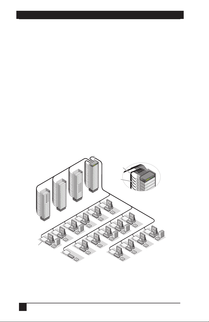
Octopus 1664 Switch
64 Servers
Octopus 1710
User Station
16 Users
Figure 2-1. Typical O ctopus Configuration
14
UTP Cables
SAM
 Loading...