

Black Box KV119A, KV119E, KV129A, KV129E Installer/user Manual
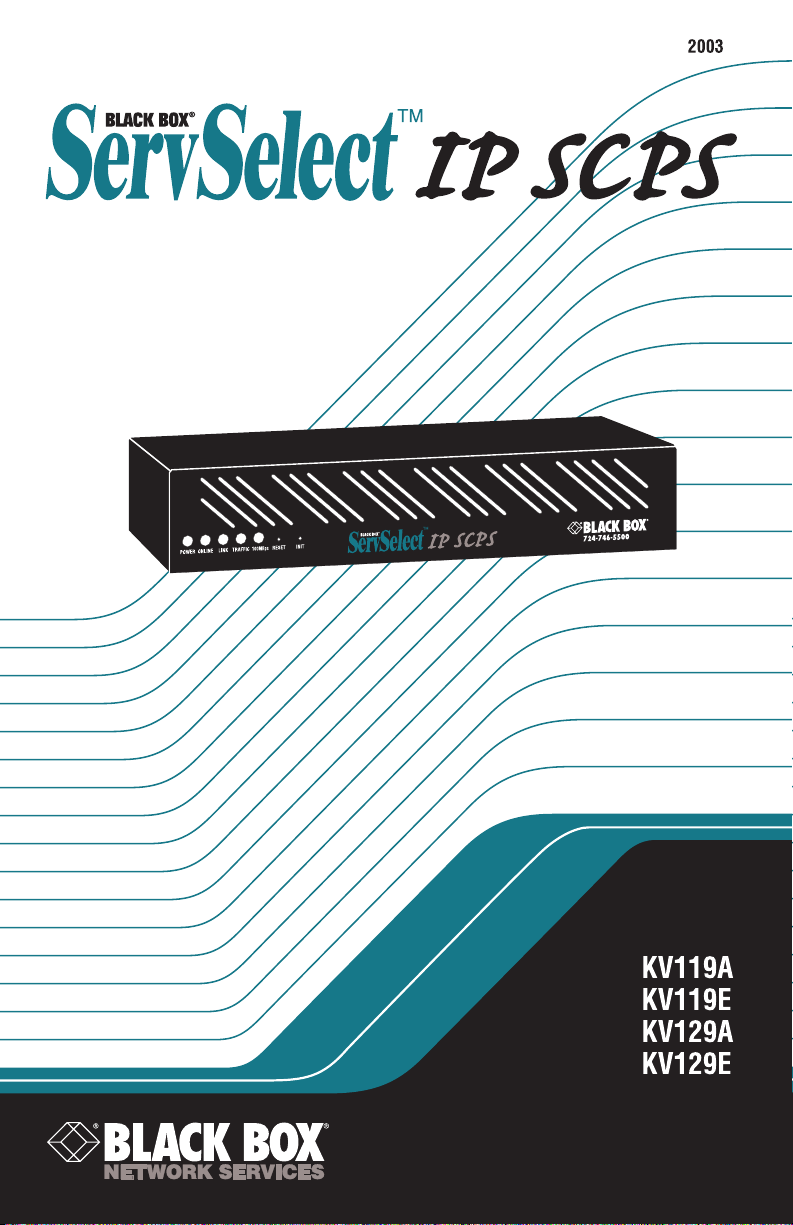

SERVSWITCH™ FAMILY
Welcome to the ServSwitch™ Family!
Thank you for purchasing a BLACK BOX® ServSwitch™ brand console port server!
We appreciate your business, and we think you’ll appreciate the many ways that this
product will save you money, time, and effort.
Our ServSwitch family is all about breaking away from the traditional, expensive
model of device management and display. You know, the one-size-fits-all-even-if-itdoesn’t model that says, “One computer gets one dedicated monitor or user station, no
more, no less.” Why not a single user station (monitor, keyboard, and mouse) or serial
console for multiple computers, routers, etc.—even computers of different platforms?
Why not a pair of user stations, each of which can control multiple computers? Why
not many monitors or user stations for the same computer? Why not access or display
any of your devices, anywhere in the world, with any of your user stations, monitors,
or consoles?
With our ServSwitch products, there’s no reason why not. We carry a broad line of
robust solutions for all these applications:
• Do you have just two PCs and need an economical alternative to keeping two
mice, keyboards, and monitors on your desk? Or do you need to share many
computers, including a mix of IBM® PC, RS/6000®, Apple® Macintosh®,
Sun Microsystems®, and SGI™ types among multiple worldwide users with
different access levels?
• Do you have to send video from one computer to two different local monitors? Or
do you need to send video from multiple computers to dozens of remote monitors?
• Do you need centralized terminal-based serial control over many sites?
• Does your switch have to sit solidly on a worktable and use regular everyday
cables? Or does it have to be mounted in an equipment rack, use convenient
many-to-one cables, and have a rackmounted user station that folds and slides
into 1U of space?
No matter how large or small your setup is, no matter how simple or how complex,
we’re confident we have a ServSwitch system that’s just right for you. Welcome to the
BLACK BOX ServSwitch™ family—the one-stop answer for all your video, serial
console, and KVM switching and extension needs!
This manual will tell you all about your new ServSelect IP SCPS, including how to
install and operate it. For an introduction to the SCPS, see Chapter 2. The Summit
product codes covered in this manual are:
KV119A KV119E KV129A KV129E
This manual also includes information about the ServSelect™ IP SCPS Rackmount
Kit, which has its own installation instructions:
*
RMK19I
1

SERVSELECT™ IP SCPS INSTALLER/USER GUIDE
FEDERAL COMMUNICATIONS COMMISSION AND
INDUSTRY CANADA
RADIO-FREQUENCY INTERFERENCE STATEMENTS
This equipment generates, uses, and can radiate radio-frequency energy and if not
installed and used properly, that is, in strict accordance with the manufacturer’s
instructions, may cause interference to radio communication. It has been tested and
found to comply with the limits for a Class A computing device in accordance with
the specifications in Subpart B of Part 15 of FCC rules, which are designed to
provide reasonable protection against such interference when the equipment is
operated in a commercial environment. Operation of this equipment in a residential
area is likely to cause interference, in which case the user at his own expense will be
required to take whatever measures may be necessary to correct the interference.
Changes or modifications not expressly approved by the party responsible for
compliance could void the user’s authority to operate the equipment.
This digital apparatus does not exceed the Class A limits for radio noise emission from
digital apparatus set out in the Radio Interference Regulation of Industry Canada.
Le présent appareil numérique n’émet pas de bruits radioélectriques dépassant les
limites applicables aux appareils numériques de la classe A prescrites dans le
Règlement sur le brouillage radioélectrique publié par Industrie Canada.
EUROPEAN UNION DECLARATION OF CONFORMITY
This equipment has been tested and found to comply with the limits for a Class A
computing device in accordance with the specifications in the European standard
EN55022. These limits are designed to provide reasonable protection against
harmful interference. This equipment generates, uses and can radiate radiofrequency energy, and if not installed and used in accordance with the instructions,
might cause harmful interference to radio or television reception.
However, there is no guarantee that harmful interference will not occur in a
particular installation. If this equipment does cause interference to radio or television
reception, which can be determined by turning the equipment on and off, you can
correct the interference with one or more of the following measures:
(a) Reorient or relocate the receiving antenna.
(b) Increase the separation between the equipment and the receiver.
(c) Connect the equipment to an outlet on a circuit different from that to which the
receiver is connected.
(d) Consult the supplier or an experienced radio/TV technician for help.
2

COMPLIANCE STATEMENTS
Shielded cables must be used with this equipment to maintain compliance with radio
frequency energy emission regulations and ensure a suitably high level of immunity
to electromagnetic disturbances. This equipment has also been found to comply with
European standards EN50082 and EN60950.
Japanese Compliance Statement
Other Agency Approvals
UL 1950, CSA C22. 2 No. 950, IEC 950
Republic of Korea EMI Standard Certificate Number: E-F900-01-2012 (A)
TRADEMARKS USED IN THIS MANUAL
BLACK BOX and the logo are registered trademarks, and ServSwitch,
ServSelect, and ServSelect IP are trademarks of BLACK BOX Corporation.
Apple, Mac, and Macintosh are registered trademarks of Apple Computer, Inc.
IBM, PS/2, and RS/6000 are registered trademarks of International Business
Machines Corporation.
Microsoft, HyperTerminal, Windows, Windows NT, and Windows XP are
trademarks or registered trademarks of Microsoft Corporation in the United States
and/or other countries.
Sun and Sun Microsystems are registered trademarks of Sun Microsystems, Inc. in
the United States and other countries.
UL is a registered trademark of Underwriters Laboratories, Inc.
Any other trademarks mentioned in this manual are acknowledged to be the property
of the trademark owners.
3

SERVSELECT™ IP SCPS INSTALLER/USER GUIDE
Normas Oficiales Mexicanas (NOM)
Electrical Safety Statement
INSTRUCCIONES DE SEGURIDAD
1. Todas las instrucciones de seguridad y operación deberán ser leídas antes de
que el aparato eléctrico sea operado.
2. Las instrucciones de seguridad y operación deberán ser guardadas para
referencia futura.
3. Todas las advertencias en el aparato eléctrico y en sus instrucciones de
operación deben ser respetadas.
4. Todas las instrucciones de operación y uso deben ser seguidas.
5. El aparato eléctrico no deberá ser usado cerca del agua—por ejemplo, cerca de
la tina de baño, lavabo, sótano mojado o cerca de una alberca, etc.
6. El aparato eléctrico debe ser usado únicamente con carritos o pedestales que
sean recomendados por el fabricante.
7. El aparato eléctrico debe ser montado a la pared o al techo sólo como sea
recomendado por el fabricante.
8. Servicio—El usuario no debe intentar dar servicio al equipo eléctrico más allá a
lo descrito en las instrucciones de operación. Todo otro servicio deberá ser
referido a personal de servicio califi cado.
9. El aparato eléctrico debe ser situado de tal manera que su posición no interfi era
su uso. La colocación del aparato eléctrico sobre una cama, sofá, alfombra o
superfi cie similar puede bloquea la ventilación, no se debe colocar en libreros o
gabinetes que impidan el fl ujo de aire por los orifi cios de ventilación.
10. El equipo eléctrico deber ser situado fuera del alcance de fuentes de calor como
radiadores, registros de calor, estufas u otros aparatos (incluyendo
amplifi cadores) que producen calor.
11. El aparato eléctrico deberá ser connectado a una fuente de poder sólo del tipo
descrito en el instructivo de operación, o como se indique en el aparato.
12. Precaución debe ser tomada de tal manera que la tierra fi sica y la polarización
del equipo no sea eliminada.
13. Los cables de la fuente de poder deben ser guiados de tal manera que no sean
pisados ni pellizcados por objetos colocados sobre o contra ellos, poniendo
particular atención a los contactos y receptáculos donde salen del aparato.
14. El equipo eléctrico debe ser limpiado únicamente de acuerdo a las
recomendaciones del fabricante.
15. En caso de existir, una antena externa deberá ser localizada lejos de las lineas
de energia.
16. El cable de corriente deberá ser desconectado del cuando el equipo no sea
usado por un largo periodo de tiempo.
4

NOM STATEMENT
17. Cuidado debe ser tomado de tal manera que objectos liquidos no sean
derramados sobre la cubierta u orifi cios de ventilación.
18. Servicio por personal califi cado deberá ser provisto cuando:
A: El cable de poder o el contacto ha sido dañado; u
B: Objectos han caído o líquido ha sido derramado dentro del aparato; o
C: El aparato ha sido expuesto a la lluvia; o
D: El aparato parece no operar normalmente o muestra un cambio en su
desempeño; o
E: El aparato ha sido tirado o su cubierta ha sido dañada.
5

SERVSELECT™ IP SCPS INSTALLER/USER GUIDE
Contents
1. Specifications . . . . . . . . . . . . . . . . . . . . . . . . . . . . . . . . . . . . . . . . . . . . . 7
2. Introduction . . . . . . . . . . . . . . . . . . . . . . . . . . . . . . . . . . . . . . . . . . . . . . .8
2.1 Features and Benefits . . . . . . . . . . . . . . . . . . . . . . . . . . . . . . . . . . . . . . . . . . . . . .8
2.2 Safety Precautions . . . . . . . . . . . . . . . . . . . . . . . . . . . . . . . . . . . . . . . . . . . . . . . . .9
3. Installation and Configuration . . . . . . . . . . . . . . . . . . . . . . . . . . . . . . .11
3.1 Hardware Overview . . . . . . . . . . . . . . . . . . . . . . . . . . . . . . . . . . . . . . . . . . . . . .11
3.2 Installing the SCPS . . . . . . . . . . . . . . . . . . . . . . . . . . . . . . . . . . . . . . . . . . . . . .12
3.3 Configuring the SCPS . . . . . . . . . . . . . . . . . . . . . . . . . . . . . . . . . . . . . . . . . . . . .12
3.4 Reinitializing the SCPS . . . . . . . . . . . . . . . . . . . . . . . . . . . . . . . . . . . . . . . . . . .16
4. Operations . . . . . . . . . . . . . . . . . . . . . . . . . . . . . . . . . . . . . . . . . . . . . . .17
4.1 Overview . . . . . . . . . . . . . . . . . . . . . . . . . . . . . . . . . . . . . . . . . . . . . . . . . . . . . . .17
4.2 Configuring Serial Port Settings . . . . . . . . . . . . . . . . . . . . . . . . . . . . . . . . . . . . .17
4.3 Connecting to Serial Devices . . . . . . . . . . . . . . . . . . . . . . . . . . . . . . . . . . . . . . .18
4.4 Managing Users . . . . . . . . . . . . . . . . . . . . . . . . . . . . . . . . . . . . . . . . . . . . . . . . .27
4.5 Using Authentication Modes . . . . . . . . . . . . . . . . . . . . . . . . . . . . . . . . . . . . . . .29
4.6 Managing the Port History Buffer . . . . . . . . . . . . . . . . . . . . . . . . . . . . . . . . . . .32
4.7 Managing SNMP Structures . . . . . . . . . . . . . . . . . . . . . . . . . . . . . . . . . . . . . . . .35
5. Using SCPS Commands . . . . . . . . . . . . . . . . . . . . . . . . . . . . . . . . . . . .39
5.1 Accessing the CLI . . . . . . . . . . . . . . . . . . . . . . . . . . . . . . . . . . . . . . . . . . . . . . . .39
5.2 Entering Commands . . . . . . . . . . . . . . . . . . . . . . . . . . . . . . . . . . . . . . . . . . . . . .39
5.3 Understanding Conventions . . . . . . . . . . . . . . . . . . . . . . . . . . . . . . . . . . . . . . . .40
5.4 Command Summary . . . . . . . . . . . . . . . . . . . . . . . . . . . . . . . . . . . . . . . . . . . . . .42
6. SCPS Commands . . . . . . . . . . . . . . . . . . . . . . . . . . . . . . . . . . . . . . . . . 45
6.1 Connect Command . . . . . . . . . . . . . . . . . . . . . . . . . . . . . . . . . . . . . . . . . . . . . . .45
6.2 Disconnect Command . . . . . . . . . . . . . . . . . . . . . . . . . . . . . . . . . . . . . . . . . . . . .45
6.3 Help Command . . . . . . . . . . . . . . . . . . . . . . . . . . . . . . . . . . . . . . . . . . . . . . . . . .45
6.4 Port Commands . . . . . . . . . . . . . . . . . . . . . . . . . . . . . . . . . . . . . . . . . . . . . . . . . .46
6.5 Quit Command . . . . . . . . . . . . . . . . . . . . . . . . . . . . . . . . . . . . . . . . . . . . . . . . . .52
6.6 Resume Command . . . . . . . . . . . . . . . . . . . . . . . . . . . . . . . . . . . . . . . . . . . . . . .52
6.7 Server Commands . . . . . . . . . . . . . . . . . . . . . . . . . . . . . . . . . . . . . . . . . . . . . . . .52
6.8 Show Commands . . . . . . . . . . . . . . . . . . . . . . . . . . . . . . . . . . . . . . . . . . . . . . . .63
6.9 User Commands . . . . . . . . . . . . . . . . . . . . . . . . . . . . . . . . . . . . . . . . . . . . . . . . .69
7. Traps . . . . . . . . . . . . . . . . . . . . . . . . . . . . . . . . . . . . . . . . . . . . . . . . . . . . 74
8. Device Cabling . . . . . . . . . . . . . . . . . . . . . . . . . . . . . . . . . . . . . . . . . . . . 77
9. Troubleshooting . . . . . . . . . . . . . . . . . . . . . . . . . . . . . . . . . . . . . . . . . . 78
9.1 Calling BLACK BOX . . . . . . . . . . . . . . . . . . . . . . . . . . . . . . . . . . . . . . . . . . . . .78
9.2 Shipping and Packaging . . . . . . . . . . . . . . . . . . . . . . . . . . . . . . . . . . . . . . . . . . .78
6

CHAPTER 1: PRODUCT OVERVIEW
1. Specifications
During the course of this product’s lifetime, modifications might be made to its
hardware or firmware that could cause these specifications to change without notice.
Agency Approvals
EN61000-3-3, EN60950, EN55024, ETL (UL1950),
CSA 22.2 No. 950
Server Ports
Number 8 (SCPS-8); 16 (SCPS-16)
Type Serial ports
Connectors Serial port RJ-45
Network Connection
Number 1
Type Ethernet: IEEE 802.3, 10BaseT
Fast Ethernet: IEEE 802.3U, 100BaseT
Connector RJ45
Other Characteristics
Dimensions (HxWxD) 4.45 x 22.23 x 20.32 cm 1U form factor
(1.75 x 8.75 x 8.00 in)
Weight 5 lbs (2.3 kg) without cables
Heat Dissipation 75 BTU/hr (SCPS-8); 102 BTU/hr (SCPS-16)
Airfl ow 2.5 cfm
Power Consumption 22 W (SCPS-8); 30 W (SCPS-16)
AC-input power 50 W maximum
AC-input maximum 90 to 267 VAC
AC-input current rating 0.5 A
AC-input cable 18 AWG three-wire cable, with a three-lead IEC-320
receptacle on the power supply end and a country
dependent plug on the power resource end
Frequency 50-60 Hz
Temperature Ø˚ to 40˚ Celsius (32˚ to 104˚ Fahrenheit) operating
-20˚ to 65˚ Celsius (-4˚ to 149˚ Fahrenheit) nonoperating
Humidity 10 to 90% noncondensing
FCC P15 Class A, EN55022, EN61000-3-2,
7
SERVSELECT™ IP SCPS INSTALLER/USER GUIDE
2. Introduction
2.1 Features and Benefits
The BLACK BOX® ServSelect™ IP SCPS is a serial over IP network appliance that
provides non-blocked access and control for multiplatform servers and serial devices
such as routers, power management devices and firewalls.
You may connect up to 8 serial devices to an SCPS-8, and 16 serial devices to an
SCPS-16. A single 10/100 Ethernet port provides network connectivity on each
SCPS. Two SCPS units may be mounted in 1U of vertical space in a standard 19
inch rack.
Figure 2-1. SCPS
Serial device access options
Access to attached serial devices is possible via a serial Command Line Interface
(CLI) connection, a PPP (Point to Point Protocol) dial-in connection to a serial CLI
modem or from a third-party Secure Shell (SSH) client.
User authentication and data security
The SCPS user database supports up to 64 user definitions, which include
usernames, passwords and/or keys, plus specifications of access rights to SCPS
ports and commands. User definitions may be changed at any time. You may choose
to have user access authenticated locally at the SCPS user database or at one or
more RADIUS (Remote Access Dial-In User Service) servers. Data security may be
enhanced via industry-standard SSH encryption methods.
Extensive command set
The SCPS offers a wide range of commands that allow administrators to easily
configure, control and display information about the SCPS operating environment,
including its ports, users and device access sessions. The user interface also offers
descriptive error message data and built-in command help information. On-board
TFTP support allows administrators to upload new functionality to SCPS units in
the field.
8
CHAPTER 2: INTRODUCTION
Device session history
Each SCPS port has a buffer that holds the most recent 64K bytes of session data. A
separate history command mode lets you navigate within a port’s current history file
and conduct tailored searches.
Managed Devices
TCP/IP
SCPS
Remote IP Connection
CAT5 Connection
Figure 2-2. Example SCPS Configuration
IP Connection
2.2 Safety Precautions
To avoid potential device problems:
• If the building has 3-phase AC power, ensure that a computer and its monitor (if
used) are on the same phase. For best results, they should be on the same circuit.
• Use only the supplied cable to connect appliances and devices. Warranties do
not apply to damage resulting from user-supplied cable.
9

SERVSELECT™ IP SCPS INSTALLER/USER GUIDE
To avoid potentially fatal shock hazard and possible damage to equipment, please
observe the following precautions:
• Do not use a 2-wire extension cord.
• Test AC outlets at the computer and monitor (if used) for proper polarity
and grounding.
• Use only with grounded outlets at both the computer and monitor. When using
a backup power supply (UPS), power the computer, the monitor and the SCPS
unit off the supply.
The AC inlet is the main disconnect.
NOTE:
Rackmount safety considerations
• Elevated Ambient Temperature: If installed in a closed rack assembly, the
operation temperature of the rack environment may be greater than room ambient. Use care not to exceed the rated maximum ambient temperature of the unit.
• Reduced Airfl ow: Installation of the equipment in a rack should be such that the
amount of airfl ow required for safe operation of the equipment is not compromised.
• Mechanical Loading: Mounting of the equipment in the rack should be such
that a hazardous condition is not achieved due to uneven
mechanical loading.
• Circuit Overloading: Consideration should be given to the connection of the
equipment to the supply circuit and the effect that overloading of circuits might
have on overcurrent protection and supply wiring. Consider equipment nameplate ratings for maximum current.
• Reliable Earthing: Reliable earthing of rack mounted equipment should be
maintained. Pay particular attention to supply connections other than direct
connections to the branch circuit (for example, use of power strips).
10

CHAPTER 3: INSTALLATION AND CONFIGURATION
3. Installation and Configuration
3.1 Hardware Overview
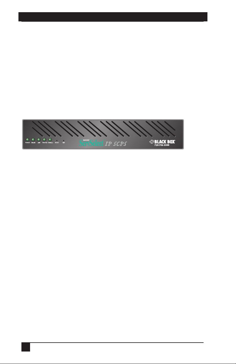
Figure 3-1 shows the front panel of an SCPS.
Figure 3-1. SCPS Front Panel
The lower left area of the front panel contains five LEDs and two buttons, which are
described in the following table.
SCPS LEDs
LED/Button Description
POWER The POWER LED illuminates when the SCPS is
connected to a power source.
ONLINE The ONLINE LED illuminates steadily (not blinking) when
the SCPS self-test and initialization procedures
complete successfully.
LINK The LINK LED illuminates when the SCPS establishes a
connection to the network.
TRAFFIC The TRAFFIC LED blinks when there is network traffi c.
100MBps The 100MBps LED illuminates when the SCPS is
connected to a 100 MBps LAN.
RESET The RESET button, when pressed, reboots the SCPS.
INIT The INIT button, when pressed, restores the SCPS to
factory defaults; for more information, see Reinitializing the
SCPS in this chapter.
As shown in Figure 3-2, the back of the SCPS contains 8 (SCPS-8) or 16 (SCPS-16)
RJ-45 connectors for serial cabling, a LAN connector for a 10BaseT or 100BaseT
interface cable and a power receptacle.
Figure 3-2. SCPS-16 Back Panel
11

SERVSELECT™ IP SCPS INSTALLER/USER GUIDE
3.2 Installing the SCPS
See Chapter 8 for device cabling information.
The power outlet should be installed near the equipment and should be easily accessible.
WARNING:
To install the SCPS hardware:
1. Locate the SCPS where you can connect cables between the serial devices and
the SCPS serial ports, and where you can connect a LAN interface cable
between the Ethernet hub or switch and the SCPS LAN connector.
If you are using an SCPS Rackmount Kit, follow the instructions included with
the kit.
2. Attach a 10BaseT or 100BaseT LAN interface cable to the LAN connector on the
back of the SCPS. The SCPS requires a CAT 5 cable for 100BaseT operation.
3. Insert the power cord into the back of the SCPS. Insert the other end of the
power cord into a grounded electrical receptacle.
4. Check that the POWER LED is illuminated. If not, check the power cable to
ensure that it is inserted snugly into the back of the SCPS. The ONLINE LED
will illuminate within one minute to indicate that the SCPS self-test is
complete. If the ONLINE LED blinks, contact Technical Support for assistance.
5. Check that the LINK LED is also illuminated. If not, check the Ethernet cable
to ensure that both ends are correctly inserted into their jacks. If the SCPS is
not correctly connected to an Ethernet hub or switch, you will not be able to
confi gure the SCPS for operation. If the SCPS is connected to a 100 MB
Ethernet hub, the 100MBps LED will also be illuminated.
6. Once the POWER, ONLINE and LINK LEDs are illuminated, remove power
from the SCPS and proceed with the confi guration process.
The SCPS and all attached devices should be p owered down before servicing the unit. Always
disconnect the power cord from the wall outlet.
WARNING:
3.3 Configuring the SCPS
To configure the SCPS, you must enter a unique IP address and the network’s subnet
mask. This information will be stored in the SCPS configuration database. During
initial login, you will specify a password for the Admin user.
12

CHAPTER 3: INSTALLATION AND CONFIGURATION
Configuring the IP address and subnet mask
You may use any of three methods to configure the SCPS IP address and subnet
mask: BootP, Telnet Command Line Interface (CLI) or the serial CLI on port 1.
These methods work as documented on most Windows and UNIX systems;
however, the actual implementation on your system may differ from the instructions
provided. Refer to your system administrator guide.
To confi gure the IP address and subnet mask using BootP:
1. Ensure that there is a BootP server on your network that is confi gured to
correctly respond to a BootP request from the SCPS. BootP servers require the
Ethernet MAC address of network devices. The SCPS Ethernet MAC address is
located on the back panel above the LAN connector. See your BootP server’s
system administrator guide for information about confi guring the BootP server.
2. After you have confi gured your network’s BootP server with the SCPS
Ethernet MAC address, IP address and subnet mask, restore power to the
SCPS and wait for the ONLINE LED to illuminate. Once this occurs, the
SCPS has completed the BootP protocol, obtained its IP address and subnet
mask and stored these in FLASH.
3. Yo u may verify that the BootP process was successful with a ping command,
which tests network connectivity. The ping command is entered as:
ping <ip_address>
For example, the following command tests the network connectivity of an SCPS
with the IP address 192.168.0.5.
ping 192.168.0.5
4. If the SCPS completes the BootP successfully, you will see a display similar to
the following.
Pinging 192.168.0.5 with 32 bytes of data:
Reply from 192.168.0.5: bytes=32 time<10ms TTL=128
Reply from 192.168.0.5: bytes=32 time<10ms TTL=128
Reply from 192.168.0.5: bytes=32 time<10ms TTL=128
Reply from 192.168.0.5: bytes=32 time<10ms TTL=128
If the SCPS did not successfully obtain its IP address with the BootP protocol,
you will see a display similar to the following.
Pinging 192.168.0.5 with 32 bytes of data:
Request timed out.
Request timed out.
Request timed out.
Request timed out.
13

SERVSELECT™ IP SCPS INSTALLER/USER GUIDE
In this case, check the MAC address and IP address provided to the BootP
server to confi rm they are correct. Verify that the Ethernet LAN adaptor cable
is correctly installed on the SCPS and the Ethernet hub.
After the IP address is configured successfully, launch a Telnet session to the SCPS
IP address. Then, see Initial SCPS login in this chapter.
To confi gure the IP address and subnet mask using a Telnet CLI:
1. Ensure that your server or workstation has a Telnet client and is located on the
same LAN segment as the SCPS.
2. Use the arp command to update the server or workstation with the SCPS IP
address and Ethernet MAC address. The SCPS Ethernet MAC address is
located on the back panel above the LAN connector. The arp command is
entered as:
arp -s <ip_address> <mac_address>
For example, the following command assigns the IP address 192.168.0.5 and
the Ethernet MAC address 00-80-7d-54-01-54 to the SCPS.
arp -s 192.168.0.5 00-80-7d-54-01-54
On a UNIX platform, the MAC address may require colons (:) instead of
dashes (-), for example, 00:80:7d:54:01:54.
3. You may verify that you entered the information correctly by using an arp
command with the -a option.
arp -a
This command shows all arp entries for the server or workstation. See your
system administrator guide if you need additional help with the arp command.
4. After the above arp command is entered correctly, launch a Telnet client to the
assigned IP address. Then, continue with Initial SCPS login in this chapter.
To confi gure the SCPS using the serial CLI:
1. By factory default, port 1 of the SCPS is confi gured for the serial CLI. To
access the serial CLI, attach a compatible device to port 1. The compatible
device types are: ASCII, VT52, VT100, VT102, VT220, VT320, IBM3151,
IBM5250 and WYSE50.
Chapter 8 lists the required cables and adaptors. You may also use any terminal
emulation program that is available on your system.
2. Confi gure your terminal or terminal emulation program as follows.
Baud rate 9600
Bits per character 8
14

CHAPTER 3: INSTALLATION AND CONFIGURATION
Parity None
Stop bits 1
Flow control None
3. Press the
Return or Enter key until a prompt appears, requesting your
username. If you do not receive a > prompt after pressing the key fi ve times,
check your cable and serial settings to be sure that they are correct.
4. Proceed to Initial SCPS login in this chapter.
After you complete the SCPS configuration, you may reconfigure the CLI on
another port or disable it completely and use port 1 with an attached device. For
more information, see Connecting to devices from the serial CLI port in Chapter 4.
Initial SCPS login
The SCPS ships with a single user defined in its user database. The first time you
connect to the SCPS via Telnet or serial CLI, you are prompted for a username.
To log in to the SCPS for the fi rst time:
1. At the Username prompt, type
user. At the password prompt, press
2. Once authentication completes, the SCPS prompts for any missing
confi guration values that are required for operation.
Admin. There is no password for the Admin
Return.
If you already provided the IP address and subnet mask, you will not be
prompted for those values again.
If you have not already provided the IP address and subnet mask, you will be
prompted for them. Enter the SCPS IP address and subnet mask using standard
dot notation.
3. You are prompted for a new Admin password. Passwords are case sensitive and
must contain 3-16 alphanumeric characters. You must enter the new password
twice to confi rm that you entered it correctly.
After you have provided the required configuration information, the following
message appears while the SCPS stores the values in its configuration database.
Configuration is being stored. Please wait.
IP Address is 192.168.0.5 with subnet mask 255.255.255.0 has
been set
New Admin password has been set
>
You have now completed the initial login, and you may enter additional commands
at the CLI prompt (>). To configure other SCPS ports, see Configuring Serial Port
Settings in Chapter 4.
15

SERVSELECT™ IP SCPS INSTALLER/USER GUIDE
3.4 Reinitializing the SCPS
Reinitializing the SCPS removes configured information. This may be useful when
reinstalling the SCPS at another location in your network.
The SCPS stores configuration information in FLASH databases. During reinitialization,
the FLASH erase has two phases. The first phase erases the SCPS configuration
database, which contains all nonvolatile data except the IP address. The second phase
erases the IP address and restores the SCPS to its factory default settings.
To reinitialize the SCPS:
1. Locate the recessed INIT button on the front of the SCPS. You will need a nonconductive, non-metallic tool that fi ts inside the recess.
2. Insert the tool in the recess, then depress and hold the button. The ONLINE
LED will blink, indicating an SCPS initialization has been requested. You have
approximately seven seconds to release the button before any action is taken.
After seven seconds, the ONLINE LED will blink more rapidly to confi rm that
the SCPS confi guration database has been erased. Continuing to hold the INIT
button for a few more seconds will erase the IP address as well. The ONLINE
LED will blink faster to confi rm the deletion.
If any portion of FLASH is erased, the SCPS reboots when the INIT button is released.
16

CHAPTER 4: OPERATIONS
4. Operations
4.1 Overview
The SCPS and its ports can be easily configured and managed to meet your
requirements for device connection, user authentication, access control, device
session information display and SNMP compliance for use with third-party network
management products. Support for SSH (Secure Shell) access via third-party clients
is also provided.
4.2 Configuring Serial Port Settings
By default, the SCPS ports are configured with the following settings.
Baud rate 9600
Bits per character 8
Parity None
Stop bits 1
Flow control None
Time-out 15 minutes
CLI access character ^D
To change serial port settings:
Issue a Port Set command. You may specify settings for one or all ports.
PORT [<port>|ALL] SET [BAUD=<baud_rate>] [SIZE=<size>]
[PARITY=<parity>] [STOP=<stop_bits>] [FLOW=<fl ow_ctrl>]
[TIMEOUT=<time-out>] [SOCKET=<socket>] [CHAR=^<cli_char>]
[TOGGLE=NONE|DTR]
For more information, see Port Set command in Chapter 6.
To display serial port settings:
Issue a Show Port command.
SHOW PORT [<port>|ALL]
The display includes configuration information plus transmit, receive and error
counts. When you request information about a single port and a user is currently
accessing that port, the display also includes the username, access rights and other
information about the current session. For more information, see Show Port
command in Chapter 6.
17

SERVSELECT™ IP SCPS INSTALLER/USER GUIDE
4.3 Connecting to Serial Devices
The SCPS offers several methods for connecting to attached serial devices: Telnet,
serial CLI, PPP and SSH.
The SCPS monitors data traffic when you are connected to an attached serial device.
You may specify a time-out value with the Server CLI command. You may also specify
a time-out value for each port with the Port Set command. When no data is received or
transmitted for the configured number of minutes, the connection is terminated.
The following time-out values are used:
• For a Telnet session, the Server CLI time-out value is used.
• For a serial port session, if the port’s confi gured time-out value is Ø, the Server
CLI time-out value is used, even if it is also Ø.
• For a serial port session, if the port’s confi gured time-out value is non-Ø, that
value is used.
Connecting to devices using Telnet
Each SCPS serial port has a unique Telnet socket number that provides a connection
to the attached serial device.
To connect to a device using Telnet:
Type
telnet, followed by the SCPS IP address and the port’s socket number, which
is 3000 plus the port number.
For example, the following Telnet command connects to the serial device attached
to port 7 of the SCPS.
telnet 192.168.0.5 3007
If an authentication method other than None has been configured for the SCPS, you
will be prompted for a username and password. Once authentication completes,
your connection is confirmed. When you successfully connect to the serial device,
you will see a display similar to the following.
Username: Myname
Password: ******
Authentication Complete
Connected to Port: 7 9600,8,N,1,XON/XOFF
Data entered at the Telnet client is written to the attached serial device. Any data
received by the SCPS from the serial device is output to your Telnet client.
18

CHAPTER 4: OPERATIONS
Connecting to devices from the serial CLI port
By factory default, port 1 of the SCPS is configured with the serial CLI, which
prohibits the use of port 1 with an attached serial device. You can configure a
different port with the serial CLI, but only one port may be configured as the serial
CLI port at one time. For example, if you attempt to enable the CLI interface on port
n, and it is already active on port p, then the CLI will automatically be disabled on
port p.
You may connect to one serial device at a time through the serial CLI port, using a
local terminal or a local PC using a terminal emulation program. If you connect an
external modem to the serial CLI port, you can also access devices through a remote
terminal or PC that can dial into the SCPS external modem. For information about
modem connections, see Configuring and using dial-in connections in this chapter
and Server CLI command in Chapter 6.
To confi gure a port for the serial CLI:
1. Issue a Server CLI command, using the Port parameter to specify the CLI port
and the Type parameter to specify the terminal type.
SERVER CLI PORT=<port> TYPE=<type>
2. To disable the CLI that was previously confi gured on a port, issue a Server CLI
command, indicating Type=Off.
For more information, see Server CLI command in Chapter 6.
To display CLI port information:
Issue a Show Server CLI command.
SHOW SERVER CLI
The display includes the CLI port number and terminal type, plus the CLI access
character. For more information, see Show Server CLI command in Chapter 6.
To connect to a device from the serial CLI port:
1. Issue a Server CLI command, using the Connect parameter to enable the use of
the Connect command from the serial CLI port.
SERVER CLI CONNECT=ON
2. Issue a Connect command to the desired port.
CONNECT <port>
19

SERVSELECT™ IP SCPS INSTALLER/USER GUIDE
3. To end a device session that was initiated with a Connect command, issue a
Disconnect command.
DISCONNECT
For more information, see Server CLI command, Connect Command and Disconnect
Command in Chapter 6.
Connecting to devices using PPP
The SCPS supports remote PPP access using an auto-answer modem that answers calls
and establishes the PPP protocol with a dial-in client.
The PPP dial-in can be used to access a remote SCPS that does not warrant a WAN
(Wide Area Network) link to the Ethernet interface. In this case, the PPP connection
allows a remote PC with Telnet capability to dial the SCPS and then establish a
Telnet connection to an SCPS port.
The PPP dial-in can also be used to access a subnet containing remote SCPS devices
in the event of a WAN link failure. In this case, the PPP provides an alternate path to
one or more remote SCPS devices.
Once the PPP connection is established, you must launch an application that
connects to the SCPS or to one of its ports. The PPP connection is only a
communications interface to the SCPS.
The SCPS implements a PPP server that uses CHAP (Challenge Authentication
Protocol). Passwords are not accepted in the clear on PPP connections.
To enable or disable a PPP server on the serial CLI port:
1. To enable a PPP server on the serial CLI port, issue a Show Server CLI
command to ensure that a serial CLI port has been defi ned.
SHOW SERVER CLI
2. Issue a Server PPP command with the Enable parameter.
SERVER PPP ENABLE LOCALIP=<local_ip> REMOTEIP=<rem_ip>
[MASK=<subnet>]
You must specify local and remote IP addresses to be used for the SCPS and
client ends of the PPP connection respectively. You are prompted to confi rm or
cancel the changes. Enter
3. To disable a PPP server, issue a Server PPP command with the
Disable parameter.
SERVER PPP DISABLE
Y to confi rm or N to cancel.
20

CHAPTER 4: OPERATIONS
For more information, see Show Server CLI command and Server PPP command in
Chapter 6.
To display PPP confi guration information:
Issue a Show Server PPP command.
SHOW SERVER PPP
For more information, see Show Server PPP command in Chapter 6.
Configuring and using dial-in connections
You can attach an external modem to the SCPS serial CLI port for dial-in serial CLI
access to the SCPS. This may be used as a backup connection if the SCPS is not
accessible from the network. It may also be used as a primary connection at remote sites
that do not have Ethernet network capability. The modem must be Hayes compatible.
To specify a modem initialization string:
1. Issue a Show Server CLI command to ensure that the port where the modem is
connected has been defi ned as the serial CLI port.
SHOW SERVER CLI
2. Issue a Server CLI command, using the Modeminit parameter to specify the
modem initialization string.
SERVER CLI MODEMINIT=“<string>”
The string must be enclosed in quotes and must include at least the command
settings ATV1 and SO=1, which cause the modem to issue verbose response
strings and to auto-answer the phone on the fi rst ring. For more information,
see Server CLI command in Chapter 6.
The modem initialization string is sent to the cabled modem when any of the
following conditions occur:
• SCPS initialization
• Detection of a transition of DSR from low to high
• Completion of a call when DCD changes from high to low
3. Upon successful modem connection, press the
prompt appears.
To display modem confi guration information:
Issue a Show Server CLI command.
SHOW SERVER CLI
Enter key until the login
21

SERVSELECT™ IP SCPS INSTALLER/USER GUIDE
For more information, see Show Server CLI command in Chapter 6.
Connecting to devices using SSH
The SCPS supports version 2 of the SSH (Secure Shell) protocol (SSH2). When
SSH is enabled, all connections to the SCPS must be made from a third-party SSH
client. Telnet cannot be used.
The SCPS SSH server operates on the standard SSH port 22. The shell for this
connection provides a CLI prompt as if you had established a Telnet connection on
port 23. The shell request for this connection is for CLI access.
The SSH server on port 22 permits TCP-IP forwarding requests (tunneling) to each
of the SCPS serial port connections and to Telnet port 23. When SSH is enabled,
Telnet connections to ports are not accepted from remote clients.
Additional SCPS SSH servers operate on TCP ports that are numbered with values
100 greater than the standard 30xx Telnet ports for the SCPS. For example, if port 7
is configured for Telnet access on port 3007, then port 3107 will be a direct SSH
connection for port 7. When SSH is enabled, Telnet port 23 connections will not be
accepted from other clients; however, connecting to Telnet port 23 can be tunneled
via a connection to SSH port 22.
SSH server keys
When SSH is enabled for the first time, all other sessions on the SCPS are
terminated and the SCPS generates an SSH server key. The key generation process
may take up to ten minutes. The key is computed at random and is stored in the
SCPS configuration database.
In most cases, the SSH server key should not be modified because most SSH clients
will associate the key with the IP address of the SCPS. During the first connection to a
new SSH server, the client will display the SSH server key and ask if you want to
store it on the SSH client. After the first connection, most SSH clients will validate the
key when connecting to the SCPS. This provides an extra layer of security because the
SSH client can verify the key sent by the server each time it connects.
When you disable SSH and later reenable it, you may either use the existing server
key or compute a new one. If you are reenabling the same server at the same IP
address, it is recommended that you use the existing key, as SSH clients may be
using it for verification. If you are moving the SCPS to another location and
changing the IP address, you may want to generate a new SSH server key.
Enabling or disabling SSH requires a reboot of the SCPS.
22

CHAPTER 4: OPERATIONS
Authenticating an SSH user
SSH is enabled and disabled with the Server SSH command. When you enable SSH,
you may specify the authentication method(s) that will be used for SSH connections.
The method may be a password, an SSH key or both. A user’s password and SSH
key are specified with a User Add or User Set command. All SSH keys must be
RSA keys. DSA keys are not supported.
The following table lists and describes the valid SSH authentication methods that
can be specified with a Server SSH command.
SSH Authentication Methods
Method Description
PW (default) SSH connections will be authenticated with a username/
password. With this method, a user’s defi nition must
include a valid password in order for that user to
authenticate an SSH session.
KEY SSH connections will be authenticated with an SSH key.
PW|KEY or KEY|PW SSH connections will be authenticated with either a
PW&KEY or KEY&PW SSH connections will be authenticated using both a
With this method, a user’s defi nition must include valid
SSH key information in order for that user to authenticate
an SSH session. For more information, see SSH user keys
in this chapter.
username/password or an SSH key. If a user has only a
password defi ned, that user must authenticate an SSH
session with a username/password. If a user has only an
SSH key defi ned, that user must authenticate an SSH
session using the key. If a user has both a password and
an SSH key defi ned, that user may use either a username/
password or the SSH key to authenticate an SSH session.
This method allows the SCPS administrator to defi ne how
each user will authenticate an SSH session based on
information provided in the User Add/Set command.
username/password and an SSH key. With this method,
a user’s defi nition must include a password and SSH key
information for that user to authenticate an SSH session.
A user’s access rights are determined from the authentication method used. SSH key
authentication always uses the access rights from the local user database. Depending
on the server authentication mode specified with the Server Security command, SSH
password authentication will use either the access rights from the local user database
or the values returned by the RADIUS server.
23

SERVSELECT™ IP SCPS INSTALLER/USER GUIDE
With either of the “or” methods (PW|KEY and KEY|PW), the user access rights are
determined from the authentication method used to authenticate the user.
With either of the “and” methods (PW&KEY and KEY&PW), the user access rights
are determined from the first method specified. If PW&KEY is specified, the access
rights from the password authentication will be used. If KEY&PW is specified, the
access rights from the key authentication will be used.
For more information, see Using Authentication Modes in this chapter.
SSH user keys
A user’s SSH key is specified in a User Add or User Set command. You may define a
key even if SSH is not currently enabled. The key can be specified in one of two ways:
• When using the SSHKEY and FTPIP keyword pair to defi ne the network location
of a user’s SSH key fi le, the SSHKEY parameter specifi es the name of the uuencoded (Unix to Unix encoded) public key fi le on an FTP server. The maximum
fi le size that can be received is 4K bytes. The FTPIP parameter specifi es the FTP
server’s IP address. When this method is specifi ed, the SCPS initiates an FTP
client request to the specifi ed IP address. The SCPS then prompts the user for
an FTP username and password for connection. When connected, the SCPS will
GET the specifi ed key fi le and the FTP connection will be closed. The SCPS then
stores the SSH key with the username in the SCPS user database.
• When using the KEY keyword to specify the SSH key, the KEY parameter
specifi es the actual uuencoded SSH key. This is for confi gurations that do
not implement an FTP server. The SCPS stores the specifi ed key in the
SCPS user database.
The SCPS processes a uuencoded SSH2 public key file with the format described in
the IETF document draft-ietf-secshpublickeyfile-02. The key must follow all format
requirements. The UNIX ssh-keygen2 generates this file format. The SCPS also
processes a uuencoded SSH1 public key file. The UNIX ssh-keygen generates this
file format.
To enable SSH session access to the SCPS:
1. Issue a Show Server Security command to ensure that you are using an
authentication method other than DS or None.
SHOW SERVER SECURITY
2. Issue a Server SSH command with the Enable parameter. You may also specify
an authentication method.
SERVER SSH ENABLE AUTH=<auth>
24

CHAPTER 4: OPERATIONS
If an authentication method is not specifi ed, the previous authentication
parameter will be used. The default value is AUTH=PW.
3. If you are enabling SSH for the fi rst time, you are advised that all other SCPS
sessions will be terminated. Enter
database is updated, you are prompted for a reboot. Enter
Y to continue or N to cancel. After the SCPS
Y to reboot or N to
cancel the reboot.
4. If you are reenabling SSH, you are prompted to use the existing SSH server
key or generate a new key. Enter
Y to use the existing key or N to generate a
new key. After the SCPS database is updated, you are prompted for a reboot.
Enter
Y to reboot or N to cancel the reboot.
For more information, see Server SSH command in Chapter 6.
To disable SSH session access to the SCPS:
1. Issue a Server SSH command with the Disable parameter.
SERVER SSH DISABLE
2. You are prompted for a reboot. Enter
Y to reboot or N to cancel the reboot.
When SSH is disabled, the SCPS operates in plain text mode.
To display SSH information:
Issue a Show Server Security command.
SHOW SERVER SECURITY
If SSH is enabled, the display will include SSH2. Regardless of whether SSH is
enabled, the display will indicate the authentication method that was specifi ed with
the Server SSH command.
CLI mode
While you are connected to an attached serial device, you may enter CLI mode and
enter SCPS commands.
To enter or exit CLI mode when connected to a serial device:
1. To enter CLI mode, type the CLI access character, which is
At the CLI prompt (>), you may enter SCPS commands.
2. To exit CLI mode and return to the session with the attached device, issue a
Resume command.
RESUME
For more information, see Resume Command in Chapter 6.
Ctrl-D by default.
25
 Loading...