

Page 1

KV104A-R3
KV108A-R3
For FREE Technical Support 24 hours a day, 7 days a week, call 724-746-5500.
Address: 1000 Park Dr., Lawrence, PA 15055-1018 • Phone: 724-746-5500 • Fax: 724-746-0746
World-Wide Web: www.blackbox.com • E-mail: info@blackbox.com
© Copyright 1999. Black Box Corporation. All rights reserved.
Customer Support Information:
FEBRUARY 1999
Page 2

1
THE SERVSWITCH™ FAMILY
Welcome to the ServSwitch
TM
Family!
Thank you for purchasing a BLACK BOX®ServSwitch™Brand KVM switch! We
appreciate your business, and we think you’ll appreciate the many ways that your
new ServSwitch keyboard/video/mouse switch will save you money, time, and
effort.
That’s because our ServSwitch family is all about breaking away from the
traditional, expensive model of computer management. You know, the one-sizefits-all-even-if-it-doesn’t model that says, “One computer gets one user station, no
more, no less.” Why not a single user station (monitor, keyboard, and mouse) for
multiple computers—even computers of different platforms? Why not a pair of
user stations, each of which can control multiple computers? Why not multiple
user stations for the same computer?
With our ServSwitch products, there’s no reason why not. We carry a broad line
of robust solutions for all these applications. Do you have just two PCs, and need
an economical alternative to keeping two monitors, keyboards, and mice on your
desk? Or do you need to share dozens of computers, including a mix of IBM
®
PC,
RS/6000
®
, Apple®Macintosh®, Sun Microsystems®, and SGI®compatibles among
multiple users with different access levels? Does your switch have to sit solidly on a
worktable and use regular everyday cables? Or does it have to be mounted in an
equipment rack and use convenient many-to-one cables? No matter how large or
small your setup is, no matter how simple or how complex, we’re confident we
have a ServSwitch system that’s just right for you.
The ServSwitch
™
family from Black Box—the one-stop answer for all your
KVM-switching needs!
*
This manual will tell you all about your new ServSelect™ unit, including how to
install, operate, and troubleshoot it. For an introduction to the ServSelect, see
Chapter 2. The ServSelect product codes covered in this manual are:
KV104A-R3
KV108A-R3
Page 3

2
SERVSELECT
™
TRADEMARKS USED IN THIS MANUAL
BLACK BOX and the logo are registered trademarks, ServSwitch and
ServSwitch Miscellaneous are trademarks, and “The World’s Source for
Connectivity” is a service mark, of Black Box Corporation.
Apple and Macintosh are registered trademarks of Apple Computer, Inc.
IBM, PC/AT, PS/2, and RS/6000 are registered trademarks, and PC/XT is a
trademark, of International Business Machines Corporation.
Logitech is a trademark of Logitech, Inc.
Microsoft and Windows are registered trademarks, and IntelliMouse is a
trademark, of Microsoft Corporation.
SGI is a registered trademark of Silicon Graphics, Inc.
Sun Microsystems is a registered trademark of Sun Microsystems, Inc.
Any other trademarks mentioned in this manual are acknowledged to be the property of the
trademark owners.
Page 4

3
FCC/IC STATEMENTS
FEDERAL COMMUNICATIONS COMMISSION
AND
INDUSTRY CANADA
RADIO FREQUENCY INTERFERENCE STATEMENTS
This equipment generates, uses, and can radiate radio frequency energy and if not
installed and used properly, that is, in strict accordance with the manufacturer’s
instructions, may cause interference to radio communication. It has been tested
and found to comply with the limits for a Class A computing device in accordance
with the specifications in Subpart J of Part 15 of FCC rules, which are designed to
provide reasonable protection against such interference when the equipment is
operated in a commercial environment. Operation of this equipment in a
residential area is likely to cause interference, in which case the user at his own
expense will be required to take whatever measures may be necessary to correct the
interference.
Changes or modifications not expressly approved by the party responsible for
compliance could void the user’s authority to operate the equipment.
This digital apparatus does not exceed the Class A limits for radio noise emission from digital
apparatus set out in the Radio Interference Regulation of Industry Canada.
Le présent appareil numérique n’émet pas de bruits radioélectriques dépassant les limites
applicables aux appareils numériques de la classe A prescrites dans le Règlement sur le
brouillage radioélectrique publié par Industrie Canada.
Page 5

4
SERVSELECT
™
NORMAS OFICIALES MEXICANAS (NOM)
ELECTRICAL SAFETY STATEMENT
INSTRUCCIONES DE SEGURIDAD
1. Todas las instrucciones de seguridad y operación deberán ser leídas antes de
que el aparato eléctrico sea operado.
2. Las instrucciones de seguridad y operación deberán ser guardadas para
referencia futura.
3. Todas las advertencias en el aparato eléctrico y en sus instrucciones de
operación deben ser respetadas.
4. Todas las instrucciones de operación y uso deben ser seguidas.
5. El aparato eléctrico no deberá ser usado cerca del agua—por ejemplo, cerca
de la tina de baño, lavabo, sótano mojado o cerca de una alberca, etc..
6. El aparato eléctrico debe ser usado únicamente con carritos o pedestales que
sean recomendados por el fabricante.
7. El aparato eléctrico debe ser montado a la pared o al techo sólo como sea
recomendado por el fabricante.
8. Servicio—El usuario no debe intentar dar servicio al equipo eléctrico más allá
a lo descrito en las instrucciones de operación. Todo otro servicio deberá ser
referido a personal de servicio calificado.
9. El aparato eléctrico debe ser situado de tal manera que su posición no
interfiera su uso. La colocación del aparato eléctrico sobre una cama, sofá,
alfombra o superficie similar puede bloquea la ventilación, no se debe colocar
en libreros o gabinetes que impidan el flujo de aire por los orificios de
ventilación.
10. El equipo eléctrico deber ser situado fuera del alcance de fuentes de calor
como radiadores, registros de calor, estufas u otros aparatos (incluyendo
amplificadores) que producen calor.
11. El aparato eléctrico deberá ser connectado a una fuente de poder sólo del
tipo descrito en el instructivo de operación, o como se indique en el aparato.
Page 6

5
NOM STATEMENT
12. Precaución debe ser tomada de tal manera que la tierra fisica y la polarización
del equipo no sea eliminada.
13. Los cables de la fuente de poder deben ser guiados de tal manera que no
sean pisados ni pellizcados por objetos colocados sobre o contra ellos,
poniendo particular atención a los contactos y receptáculos donde salen del
aparato.
14. El equipo eléctrico debe ser limpiado únicamente de acuerdo a las
recomendaciones del fabricante.
15. En caso de existir, una antena externa deberá ser localizada lejos de las lineas
de energia.
16. El cable de corriente deberá ser desconectado del cuando el equipo no sea
usado por un largo periodo de tiempo.
17. Cuidado debe ser tomado de tal manera que objectos liquidos no sean
derramados sobre la cubierta u orificios de ventilación.
18. Servicio por personal calificado deberá ser provisto cuando:
A: El cable de poder o el contacto ha sido dañado; u
B: Objectos han caído o líquido ha sido derramado dentro del aparato; o
C: El aparato ha sido expuesto a la lluvia; o
D: El aparato parece no operar normalmente o muestra un cambio en su
desempeño; o
E: El aparato ha sido tirado o su cubierta ha sido dañada.
Page 7

6
SERVSELECT
™
Contents
Chapter Page
1. Specifications ............................................................................................. 8
2. Introduction ............................................................................................. 10
3. Installation ................................................................................................ 13
3.1 Basic Installation ............................................................................... 13
3.2 Cascaded Installation ........................................................................ 15
3.3 Paired Installation ............................................................................. 17
3.3.1 Configuring the Slave ServSelect ........................................... 17
3.3.2 Configuring the Master ServSelect ........................................ 19
3.3.3 Installing the ServSelects and the User Station and
Their Cabling ..................................................................... 19
3.3.4 Connecting Computers and Power to the Paired System .... 20
3.3.5 Decoupling Paired Units (Uninstalling/Deactivating
Pairing) ............................................................................... 21
4. Operation ................................................................................................. 22
4.1 Operation Overview .......................................................................... 22
4.2 Operating the ServSelect with the Shared Keyboard ..................... 23
4.2.1 Keystroke Notation ................................................................. 23
4.2.2 Keyboard-Based Switching ...................................................... 24
4.2.3 Other Keyboard Commands .................................................. 25
4.3 Operating the ServSelect with Its On-Screen Display (OSD) ........ 27
4.3.1 Activating OSD ........................................................................ 27
4.3.2 The Main OSD Window .......................................................... 28
4.3.3 The Command Menu ............................................................. 29
4.3.4 Channel Maintenance ............................................................ 30
4.3.4.A Adding New Channels to a Single ServSelect ......... 30
4.3.4.B Adding New Channels to a Paired System .............. 31
4.3.4.C Adding New Channels to a Cascade ......................... 31
4.3.4.D Deleting an Existing Channel ................................... 32
4.3.4.E Changing Channel Names and Addresses ............... 32
4.3.5 The ID Window ....................................................................... 33
4.3.5.A Changing the Size, Color, and Position of the
ID Window ............................................................ 33
4.3.5.B Setting the ID Window’s Dwell Time ....................... 33
Page 8

7
TABLE OF CONTENTS
Chapter Page
4. Operation (continued)
4.3 Operating the ServSelect with Its OSD (continued)
4.3.6 Administrator Functions ......................................................... 34
4.3.6.A Creating the Administrator Password ...................... 35
4.3.6.B Setting the Administrator’s Logout Time ................ 35
4.3.6.C Setting Up Additional Users ..................................... 36
4.4 Scanning Channels ........................................................................... 37
4.4.1 Choosing a Scanning Method ................................................ 37
4.4.2 Turning Scanning ON and OFF ............................................ 38
4.4.2.A Turning Scanning ON and OFF Through OSD ...... 38
4.4.2.B Turning Scanning ON and OFF with the SELECT/
SCAN Button (Nonsecure Mode Only) .............. 38
4.4.2.C Turning Scanning ON and OFF with Keyboard
Hotkey Commands (System Administrator or
Nonsecure Mode Only) ....................................... 38
4.4.3 Setting the Scan Dwell Time (System Administrator or
Nonsecure Mode Only) ..................................................... 39
4.4.3.A Setting the Dwell Time for Sequential Scanning .... 39
4.4.3.B Setting the Dwell Time for Alphanumeric
Scanning ................................................................ 39
4.4.4 Scanning and Security ............................................................ 39
5. Troubleshooting ...................................................................................... 40
5.1 Common Problems ........................................................................... 40
5.2 Calling Black Box .............................................................................. 45
5.3 Shipping and Packaging ................................................................... 45
Appendix A: Problem Report ........................................................................ 46
Appendix B: Rackmounting the ServSelect .................................................. 49
Page 9

8
SERVSELECT
™
1. Specifications
Compliance — EMI/RFI: CE (EN55022, EN50082); FCC Part 15
Subpart J Class A, IC Class/classe A;
Electrical Safety: UL 1950, CSA 22.2 No. 950, EN60950
Standards — VGA, SVGA, XGA, or XGA-2 video
Interfaces — VIDEO port: VGA/SVGA; with adapter, XGA/XGA-2;
KBD and MSE ports: IBM PS/2 peripheral input;
Lettered channel ports: Proprietary composites of:
• IBM PC/AT or PS/2 keyboard;
• RS-232 or PS/2 mouse; and
• VGA, SVGA, XGA, or XGA-2 video
Resolution — At up to 75 Hz: Up to 1024 x 768 noninterlaced;
At up to 60 Hz: Up to 1280 x 1024 noninterlaced
Maximum
Distance — 30 ft. (9.1 m) to any attached CPU; the shared monitor,
keyboard, and mouse should be plugged directly into the
unit and should not be placed farther away than their
native cables can reach.
User Controls — On-screen function menu;
Keyboard commands;
(1) Rear-mounted ON/OFF rocker switch;
(1) Front-mounted SELECT/SCAN pushbutton;
KV104A-R3: (4) Front-mounted port-selection pushbuttons;
KV108A-R3: (8) Front-mounted port-selection pushbuttons
Indicators — On-screen display;
Front-mounted:
(2) SELECT/SCAN LEDs;
(2) STATUS LEDs;
KV104A-R3: (4) CPU Power LEDs, (4) Selected CPU
LEDs;
KV108A-R3: (8) CPU Power LEDs, (8) Selected CPU
LEDs
Page 10

9
CHAPTER 1: Specifications
Connectors — All rear-mounted:
(1) HD15 female for video;
(1) DB9 female reserved for future use;
(2) 6-pin mini-DIN female:
(1) for keyboard input,
(1) for mouse input
KV104A-R3: (4) DB25 male CPU ports;
KV108A-R3: (8) DB25 male CPU ports
Temperature
Tolerance — Operating: 41 to 104˚F (5 to 40 C);
Storage: –4 to 122˚F (–20 to 50 C)
Humidity
Tolerance — Up to 90% noncondensing
Enslosure — Steel
Power — Input: 100 to 240 VAC at 50 to 60 Hz from utility-power
outlet, through detachable power cord and IEC 320
male inlet, to internal transformer;
Consumption: 8 watts
Size — 1.7"H x 17.2"W x 6.5"D (4.5 x 43.7 x 16.5 cm)
Weight — 4.2 lb. (1.9 kg)
Page 11

10
SERVSELECT
™
2. Introduction
The ServSelect™ allows you to control as many as 64 PCs with one keyboard,
monitor, and mouse. Each computer can be up to 30 feet (9.8 m) away from the
ServSelect. The ServSelect works with IBM
®
PC/AT®and PS/2®systems and
100% compatible machines, with support for VGA, SVGA, XGA, and XGA-2 video.
Each unit of our 4-port model (product code KV104A-R2) and 8-port model
(product code KV108A-R2) can be directly attached to the corresponding number
of computers or subsidiary ServSelect™ or ServSwitch Multi™ units.
Here are some of the useful features of the ServSelect:
• Expansion for up to 64 computers. A ServSelect unit will support from one to
eight attached PCs (“channels”). If more than eight channels are needed,
multiple units can be cascaded together for expansion. Up to 2 tiers of units
can be connected for a total of 64 attached computers in one system.
• AutoBoot technology. The AutoBoot feature boots all attached servers during
initial power-up or after a power failure. PCs are booted transparently without
operator intervention, and may be powered up one at a time or all at once.
When the power stabilizes, a channel may be selected. The first available
channel is automatically selected upon power-up of the “base” (master)
ServSelect.
• On-screen display capability. Configure and control your ServSelect with on-
screen menuing! Name your computer channels anything you wish, then select
the desired computer from an easy-to-use menu. Secondary menus let you
configure and initiate channel scanning and other system features.
• Advanced security for total control over system access. Use the advanced
bi-level security feature to configure and control server access for every type of
user in the system. The administrator has full access privileges; individual users
can have viewing or viewing/editing capability for each attached server.
• IntelliMouse™. The ServSelect offers full support for the Microsoft
®
IntelliMouse.
• OSD Configuration Utility. The OSD Configuration Utility allows the
administrator to easily configure and download a channel list with defined
users and access privileges to the entire system. This utility will also read and
save your current configuration for extra security.
Page 12
11
CHAPTER 2: Introduction
• Pushbutton & keyboard switching. In addition to using the on-screen menus,
you can switch computer channels in one of three easy ways: with the
ServSelect channel pushbuttons, the SELECT/SCAN button, or a simple
sequence of keystrokes.
• Keep Alive feature. The “Keep Alive” feature allows attached servers to power
the ServSelect in case the ServSelect loses AC power. This prevents attached
PCs from locking up and keeps you from losing time and data.
• PS/2 mouse translation. For added compatibility with your current equipment,
ServSelect can “translate” the signals of your shared PS/2 mouse. Operated
through the ServSelect, your PS/2 mouse will work with any attached PC—
regardless of whether the computer is designed for a serial or PS/2 mouse!
• Built-in scanning capabilities. A built-in scanning feature allows you to
automatically “scan” (monitor) your PCs without intervention. When keyboard
activity is detected, scanning is suspended until all activity stops. Scanning then
resumes with the next channel in sequence.
• Status-indicator LEDs. Indicator LEDs give you constant readings on the status
of your ServSelect unit. Status, scanning, and channel LEDs take the guesswork
out of system operation and diagnostics.
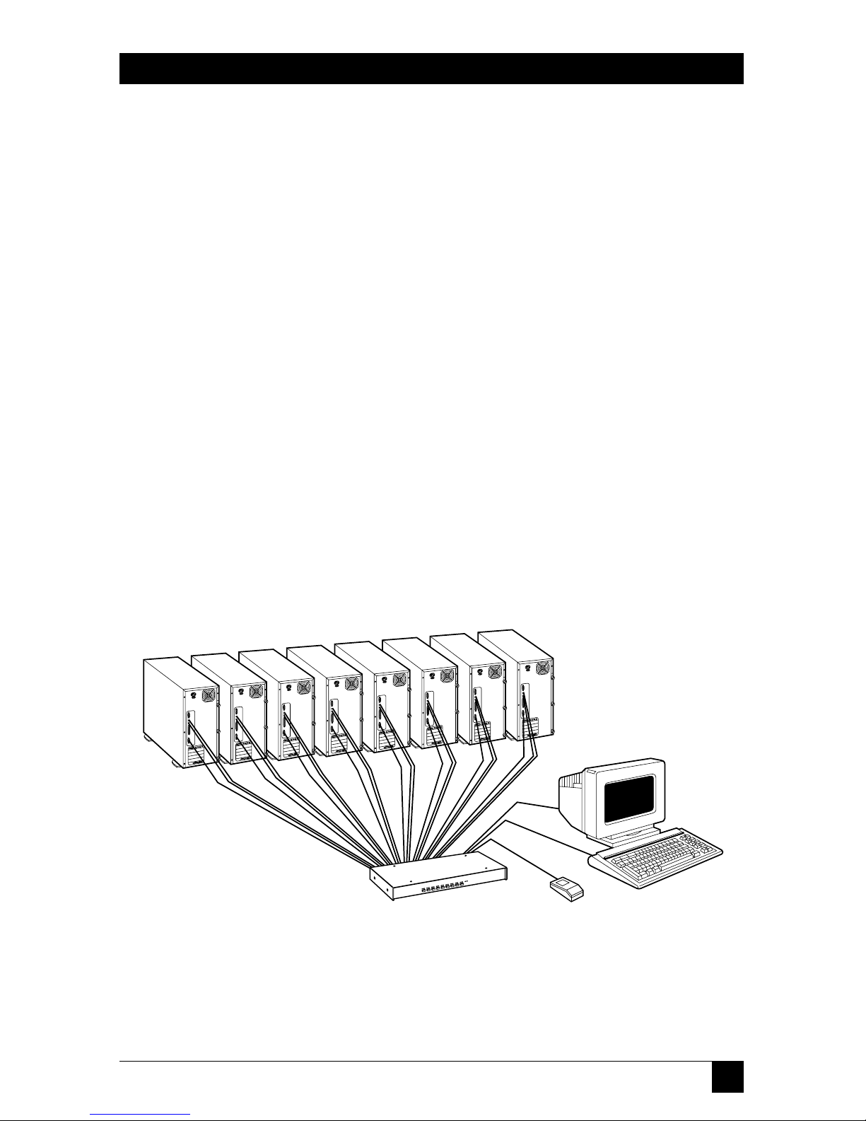
A typical ServSelect configuration is shown in Figure 2-1 below:
Figure 2-1. A KV108A-R2 in its maximum (eight-computer) single-unit
configuration.
Page 13

12
SERVSELECT
™
A few compatibility issues you should be aware of:
• Mouse/keyboard: The ServSelect requires a PS/2 style mouse and keyboard. It
is known to be compatible with these mice:
IBM PS/2 style
Microsoft serial and PS/2 style (switchable) mouse in PS/2 mode
Kensington™
Logitech
®
Trackman™
Logitech Mouseman™ (for PS/2)
Microsoft IntelliMouse
Other manufacturers’ mice might also work with the ServSelect. If you
experience problems using an untested mouse, contact Black Box Technical
Support with the manufacturer and model number of the mouse.
• Video: If you want to use XGA or XGA-II video, you will need to purchase a
special adapter; call Black Box Technical Support.
Page 14
13
CHAPTER 3: Installation
3. Installation
3.1 Basic Installation
To perform a basic (single-unit) ServSelect installation, take these steps:
1. Power down all computers that will be part of your ServSelect system.
2. Put your ServSelect, PS/2 keyboard, video monitor, and PS/2 mouse where
you want them to be.
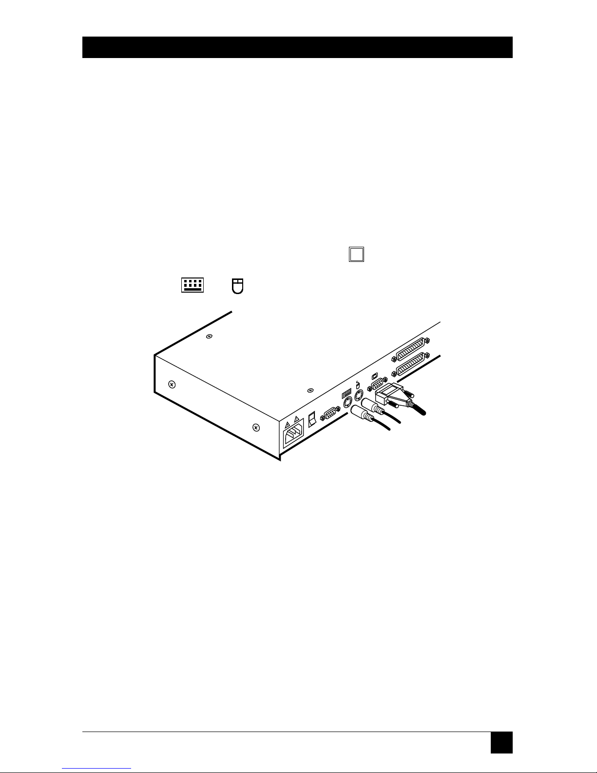
3. Plug your monitor cable into the port labeled on the back of your
ServSelect. Plug the cables from your PS/2 keyboard and mouse into the
ports labeled and respectively. Refer to Figure 3-1 below.
Figure 3-1. User-station connections.
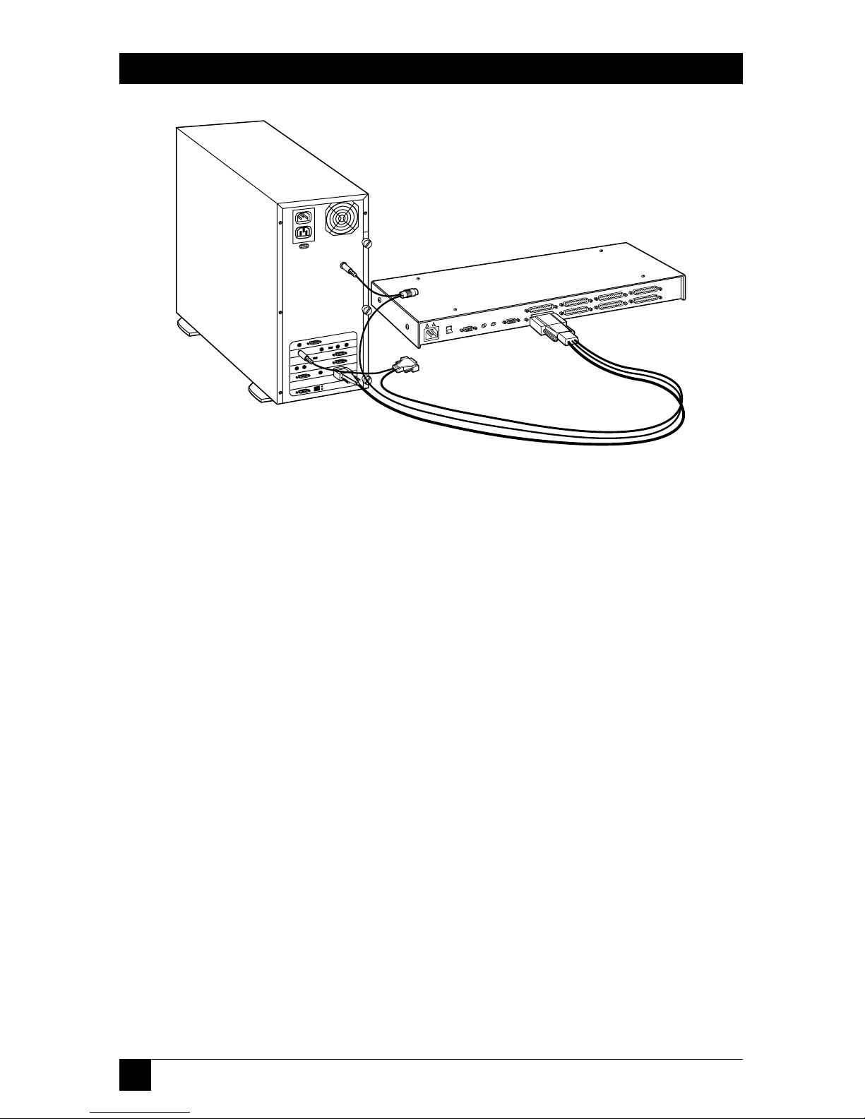
4. Get a computer-input cable (our product code EHN056). Plug the DB25
female connector at one end of this cable into any lettered channel port
on the rear of the ServSelect. The other end of the input cable will have five
connectors: an HD15 male connector for your video port, 5-pin DlN male
and 6-pin mini-DIN male connectors for your AT or PS/2 keyboard port
respectively, and DB9 female and 6-pin mini-DIN male connectors for your
serial or PS/2 mouse port respectively. (The 6-pin mini-DIN PS/2 mouse
connector is marked with a yellow band or mouse icon to distinguish it from
the 6-pin mini-DIN keyboard connector.) Plug these connectors into the
correpsonding ports; make sure to use only the keyboard and mouse
connectors that are appropriate for your PC, and leave the others
unconnected. Refer to Figure 3-2 on the next page.
Page 15
14
SERVSELECT
™
Figure 3-2. Computer connections.
5. Repeat step 4 until all computers are properly attached to the ServSelect.
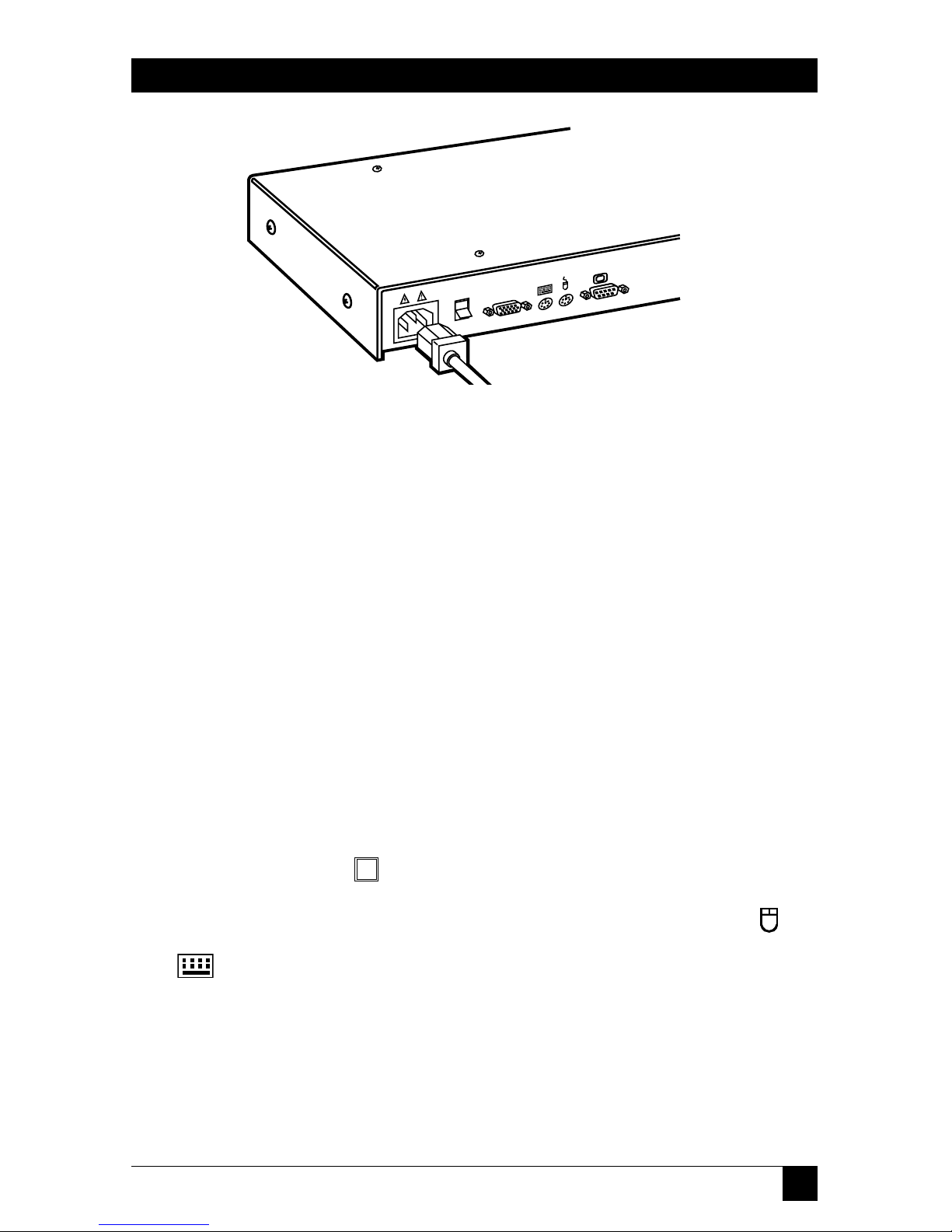
6. Get the power cord that came with your ServSelect unit. Plug it into the
power inlet on the ServSelect. Make sure that the ServSelect’s power switch is
off, then plug the other end of the power cord into an appropriate AC wall
outlet. This outlet should be near the equipment and easily accessible so that
you can quickly unplug the ServSelect should you need to move or service it.
Refer to Figure 3-3 on the next page.
7. Power up your ServSelect unit first, then all attached computers.
Your ServSelect system should be ready for continuous operation.
CAUTION!
Power down the ServSelect and all attached computers, and unplug the
ServSelect as well, before you move or service the unit.
Page 16
15
CHAPTER 3: Installation
Figure 3-3. Power connection.
3.2 Cascaded Installation
Take these steps to interconnect (cascade) multiple ServSelect units, using a
ServSelect’s CPU port each time, so that the ServSelects remain distinct from each
other and so that the system can be expanded beyond 16 ports (as opposed to
pairing units—see the next section):
1. Choose one of your ServSelects to be the “base unit” (the unit to which the
keyboard, mouse, and monitor will be attached). Follow steps 1 through 3 in
Section 3.1 for this unit.
2. All other ServSelects will be subsidiary “expansion units.” Place (one of) the
expansion unit(s) near the base unit (you can even stack it on top of the base
unit if you like).
3. Plug the DB25 connector of an EHN056 input cable into any available
lettered channel port on the rear of your base unit.
4. Into the port labeled on your expansion unit, plug the HD15 video connector on one of the other ends of the cable. Plug the 6-pin mini-DIN PS/2
mouse connector, designated by a yellow band or mouse icon, into the
port. Plug the remaining 6-pin mini-DlN keyboard connector into the
port. (The cable’s DB9 and 5-pin DIN connectors are not used for
cascading.) Refer to Figure 3-4 on the next page.
5. If you have other expansion units, repeat steps 2 through 4 for each of them.
Be careful to plug all expansion units into the base unit only. Do not attach
any expansion units to other expansion units.
Page 17

16
SERVSELECT
™
Figure 3-4. Cascade connection.
6. Follow steps 4 and 5 in Section 3.1 for each of your expansion units and your
base unit (if the base unit still has any free channel ports).
7. Follow step 6 in Section 3.1 for all of your ServSelect units.
8. Power up all of your ServSelect units first, then all attached computers.
Your ServSelect system should be ready for continuous operation.
CAUTION!
Power down all of the ServSelects and all attached computers, and
unplug the ServSelects as well, before you move or service any of the
units.
Page 18

17
CHAPTER 3: Installation
3.3 Paired Configuration/Installation
Rather than cascade units (see the previous section), you can take the steps
described in this section to serially interconnect (pair) two 4- or 8-port ServSelect
units—in any combination—without using any CPU ports, so that they function as
a single 8-, 12-, or 16-port box. First choose which of your ServSelects will be the
“master unit” and which will be the “slave unit.” Then configure the “slave” unit
(Section 3.3.1), configure the “master” (Section 3.3.2), permanently install both
units and the user station and cable them together (Section 3.3.3), and finally
connect your computers (Section 3.3.4). To add channels to your system later,
follow the directions in Section 4.3.4.B. To decouple paired ServSelects, see
Section 3.3.5.
IMPORTANT NOTE
Before installing a paired system, be aware that paired ServSelects can’t
be cascaded. They also can’t perform keyboard-based switching,
although all other keyboard commands and controls function normally.
This means that, in secure mode, you can only switch channels in a
paired system through the on-screen display (see Section 4.3.2).
3.3.1 C
ONFIGURING THE
S
LAVESERVSELECT
1. Plug your monitor cable into the port labeled on the back of your slave
ServSelect. Plug the cable from your PS/2 keyboard into the port labeled
. Refer to Figure 3-5 below.
Figure 3-5. User-station connections for configuring paired units.
2. Get the power cord that came with your slave ServSelect unit. Plug it into the
power inlet on the back of the ServSelect. Make sure that the ServSelect’s
power switch is off, then plug the other end of the power cord into an
appropriate AC wall outlet. Refer to Figure 3-3 on page 15.
3. Turn on the slave ServSelect and press the keyboard’s [Ctrl] (control) key
twice to activate the unit’s On-Screen Display system (see Section 4.3). The
Administrator Channel list will appear in a pop-up menu.
Page 19

18
SERVSELECT
™
4. Press the [Ctrl] key twice more to activate the Command Menu, as shown in
Figure 3-6 below.
Figure 3-6. The Command Menu.
5. Using the keyboard’s arrow keys, highlight “Administrator Functions”
and press [Enter]. This will bring up the Administrator Menu.
6. From here, highlight and select “Unit Configuration.”
7. Change the unit’s configuration to option 3, “Paired (Slave),” as shown
in Figure 3-7 below.
Figure 3-7. Setting the unit to a slave configuration.
Program Manager
ServSelect Control Panel
Command Menu
ENTER-accept ESC-previous
Select Unit Configuration
1: Tiered (default)
2: Paired (Master)
3: Paired (Slave)
Program Manager
ServSelect Control Panel
Command Menu
ENTER-accept ESC-previous
Channel Maintenance
Administrator Functions
Turn Scanning ON
Scanning Order
Sequential Scan Dwell Time
Reset Standard Mouse/Keyboard
Reset Wheel Mouse/Keyboard
Version Information
Page 20

19
CHAPTER 3: Installation
8. Press [Enter] to save your selection. Next, press the [Esc] key repeatedly
to exit from the OSD system.
9. Turn off the slave ServSelect and disconnect the keyboard and monitor
from it.
3.3.2 C
ONFIGURING THE
M
ASTERSERVSELECT
1. Do steps 2 through 7 of Section 3.3.1 with the master ServSelect instead of the
slave.
2. Change the configuration of the master unit to option 2, “Paired (Master).”
Press [Enter] to save your selection, then press the [Esc] key repeatedly to
exit from the OSD system again.
3. Turn off the master ServSelect and disconnect the keyboard and monitor
from it.
3.3.3 I
NSTALLING THESERVSELECTS AND THEUSERSTATION ANDTHEIRCABLING
1. Get a ServSelect Pairing Cable Kit (our product code EHN056-BOND). It will
include (1) video V-cable, with two HD15 male connectors and one HD15
female connector, and (1) DB9 male to DB9 male serial cable.
2. Plug each of the V-cable’s male connectors into one of the ServSelects’
ports: one into the master unit’s, the other into the slave unit’s. Attach a
monitor to the paired units by plugging the monitor cable into the V-cable’s
female connector. Refer to Figure 3-8 below.
Figure 3-8. Attaching the Pairing Cable Kit’s V-cable.
Page 21

20
SERVSELECT
™
3. Run the DB9 serial cable between the “SETUP” ports on the master and slave
units as shown in Figure 3-9 below.
Figure 3-9. Attaching the Pairing Cable Kit’s serial cable.
4. Attach a PS/2 keyboard to the paired units by plugging it into the port
on the master ServSelect. Attach a PS/2 mouse to the paired units by
plugging it into the port on the master ServSelect.
3.3.4 C
ONNECTINGCOMPUTERS ANDPOWER TO THEPAIREDSYSTEM
1. Do step 4 of Section 3.1 for each of your first eight computers, attaching them
to the master ServSelect.
2. Do step 4 of Section 3.1 for each of your remaining computers, attaching
them to the slave ServSelect.
3. Do step 6 of Section 3.1 for each of the paired ServSelects.
4. Power up your slave ServSelect first, then the master ServSelect, then all
attached computers.
Your ServSelect system should be ready for continuous operation.
CAUTION!
Power down the ServSelects and all attached computers, and unplug
the ServSelects as well, before you move or service either unit.
Page 22

21
CHAPTER 3: Installation
3.3.5 D
ECOUPLING
P
AIREDUNITS(UNINSTALLING/DEACTIVATINGPAIRING
)
If you need to decouple (separate) a paired ServSelect system, take these steps:
1. Press the keyboard’s [Ctrl] (control) key twice to activate the system’s
On-Screen Display system (see Section 4.3). The Administrator Channel list
will appear in a pop-up menu.
2. Press the [Ctrl] key twice more to activate the Command Menu, as shown
in Figure 3-6 on page 18.
3. Using the keyboard’s arrow keys, highlight “Administrator Functions”
and press [Enter]. This will bring up the Administrator Menu.
4. From here, highlight and select “Unit Configuration.”
5. Change the configuration to option 1, “Tiered.” (This will affect the master
unit only.)
6. Press [Enter] to save your selection and [Esc] to exit the OSD system.
7. Disconnect the Pairing Cable Kit cables from the formerly paired units.
8. Attach a monitor and keyboard directly to the slave unit.
9. Repeat steps 1 through 6 for the slave unit.
You can now use the two ServSelects separately or as part of a cascade. Please note
that after decoupling a ServSelect pair, if there were any computers attached to
your slave unit, you will need to modify the channel lists of both units according to
the basic Channel Maintenance instructions in Section 4.3.4.
Page 23

22
SERVSELECT
™
4. Operation
4.1 Operation Overview
You can operate your ServSelect in “nonsecure” mode (no password required) or
“secure” mode (password required). All units ship factory-set to the nonsecure
mode. For information on implementing password security, see Section 4.3.6.
You can power up the PCs attached to the ServSelect one at a time or all at once.
No operator intervention is required during booting. As the system stabilizes, each
occupied channel’s green LED will light, indicating that the attached computer is
powered on. The amber LED of the active computer’s channel will also light. A PC
may now be selected with the on-screen display menu or, if you are in nonsecure
mode, with the channel pushbuttons, the SELECT/SCAN button, or a keyboard
hotkey sequence.
The SELECT/SCAN pushbutton on the ServSelect’s front panel (which is shown
in Figure 4-1 below) has two LEDs over it. When you press and quickly release the
button to switch to the next computer in sequence, the amber LED will light
briefly during the channel switch. After you press and hold the button for a full
second to initiate channel scanning, the green LED will light while you are in scan
mode.
There are also two status LEDs on the unit’s front panel. The red LED lights if
one of the ServSelect’s internal components fails. The green LED will blink for
several seconds during power-up while the system performs a self-diagnostic. After
initialization, the green LED remains lit during normal operation and blinks only
when you are in Command Mode.
Figure 4-1. Front panel of the ServSelect.
Program Manager
ServSelect Control Panel
Configure Channel
Page 24

23
CHAPTER 4: Operation
4.2 Operating the ServSelect with the Shared Keyboard
4.2.1 K
EYSTROKENOTATION
Throughout the rest of this chapter, we use some “shorthand” to abbreviate certain
keystroke sequences and variables you can use to control the ServSelect switch
through the shared keyboard:
<CM> Enter Command Mode:
1. Press and hold down the keyboard’s [Num Lock] key.
2. Press and release the [–] (minus) key on the numeric keypad.
3. Release the [Num Lock] key.
Note: To choose an alternate hotkey sequence for entering
Command Mode, see Section 4.2.3.
[Enter] Press the keyboard’s Enter or Return key. Doing so will cause the
ServSelect to execute the command you just typed in and then exit
from Command Mode.
Addr The “address” of the computer you’re selecting. In single-unit
ServSelect systems, this address will correspond to the single letter
designation (“A” through “H”) of the channel port on the ServSelect
that the computer is attached to. For example, “D” is the address of
the computer attached to channel port D on a single ServSelect.
In paired systems this address will correspond to the letter
designation of the ServSelect (“A” for the master, “B” for the slave)
followed by the letter designation of the computer’s channel port.
For example, “BB” is the address of the computer attached to channel
port B on a slave paired ServSelect.
In cascaded systems this address will correspond to the letter
designation of the channel port on the base unit that the expansion is
attached to, followed by the designation of the channel port on the
expansion unit that the computer is attached to. For example, “AE” is
the address of a computer attached to channel port E of an
expansion ServSelect which in turn is attached to port A of the base
ServSelect.
[Esc] Press the keyboard’s Escape key. Doing so will cause the ServSelect to
exit from (abort) Command Mode without executing any instruction.
Page 25

24
SERVSELECT
™
4.2.2 K
EYBOARD
-B
ASEDSWITCHING
One of the ways to change the active channel in a non-secured, non-paired
ServSelect system is by entering a short sequence of keystrokes on the shared
keyboard. This is called “keyboard-based switching” or “hotkey switching,” and is
only available when the ServSelect is not paired (see Section 3.3) and is in its
default nonsecure state. For more information on secure versus nonsecure
operation, see the Section 4.3.6. To keyboard-switch channels, take these steps:
1. The first set of keystrokes (see the desription of <CM> in Section 4.2.1) places
your system in Command Mode. As long as you are operating in Command
Mode, whatever you type will be interpreted as channel-switching commands
until you press the Enter or Escape key to terminate Command Mode. None
of the keystrokes entered will be forwarded to the attached computer until
you exit Command Mode.
2. Next, enter the address (“Addr”—see the description in Section 4.2.1) for the
channel you wish to select.
3. Press [Enter] to accept the new channel.
All together, the proper format for keyboard switching to a new active channel
through the keyboard is “<CM>Addr[Enter]”. Below is a sample of a keyboard
switching session, with an accompanying explanation for each step:
1. Use “<CM>E[Enter]” to select channel E on the base unit as the active
channel.
2. Use “<CM>CF[Enter]” to access the expansion unit on channel C of the base
unit and select channel F on that expansion unit as the active channel.
3. Use “<CM>G[Enter]” to select channel G on the base unit as the active
channel.
4. Entering “<CM>BA[Esc]” gets you out of Command Mode without any
channel switch or other instruction being executed. When you press [Esc],
the “BA” you typed is ignored, and channel G remains selected as the active
channel.
Page 26

25
CHAPTER 4: Operation
4.2.3 O
THER
K
EYBOARDCOMMANDS
You can use these keyboard commands for system control and maintenance:
<CM>Kn[Enter] Sets the keyboard scan mode (1, 2, or 3). Scan mode 2 is
used by the vast majority of CPUs, and is also the default
state of all 101-key and PS/2 keyboards. Mode 1 is used
primarily by certain PS/2 CPUs. Mode 3 is used by RS/6000
®
CPUs, some other UNIX®based computers, and certain
specialized servers.
<CM>MR[Enter] If you hot-plug your mouse cable (insert it while the
ServSelect is operating), you may lose the mouse signal. Use
this command to restore the signal if you are using a PC with
a standard PS/2 mouse driver.
<CM>MW[Enter] If you hot-plug your mouse cable (insert it while the
ServSelect is operating), you may lose the mouse signal. Use
this command to restore the signal if you are using a PC with
a Microsoft IntelliMouse driver.
<CM>AV[Enter] Displays the current firmware version of the processors
inside your ServSelect unit. You must be either at a DOS
prompt or in a text editor or word processor to view this
information.
<CM>H1[Enter] Changes the Command-Mode hotkey sequence to the
default:
1. Press and hold down the [Num Lock] key.
2. Press and release the [–] (minus) key on the numeric
keypad.
3. Release the [Num Lock] key.
<CM>H2[Enter] Changes the Command-Mode hotkey sequence to the first
alternate:
1. Press and hold down the [Num Lock] key.
2. Press and release the [*] (asterisk) key on the numeric
keypad.
3. Release the [Num Lock] key.
<CM>H3[Enter] Changes the Command-Mode hotkey sequence to the
second alternate:
1. Press and hold down the [Ctrl] (control) key.
2. Press and release the [~] (tilde) key.
3. Release the [Ctrl] key.
Page 27

26
SERVSELECT
™
<CM>ZM[Enter] Use this command to resynchronize the mouse if it loses
synchronization, which can happen when you hot-plug a
device or computer (plug the device or computer into an
operating ServSelect system). Repeat, if necessary, until
synchronization is re-established.
Be careful: Using this command while the mouse is
operating correctly will cause the mouse to lose synchronization. (If this happens, send the command again until the
mouse works right.)
Page 28

27
CHAPTER 4: Operation
4.3 Operating the ServSelect with Its On-Screen Display (OSD)
4.3.1 A
CTIVATING
OSD
Activate on-screen display (OSD) by pressing either of the shared keyboard’s [Ctrl]
(control) keys twice within one second. In nonsecure mode, this brings up the
main OSD window titled “Administrator Channel List.”
In secure mode, activating OSD will bring up the “User Login” window. Type in
your user name and press [Enter]. The system administrator should login as
“Admin,” “Root,” or “Administrator.” If the user name is valid, the password
window will appear. Type your password and press [Enter]. This will bring up your
“Channel List.” If there is no keyboard activity, the login window will time out after
five minutes and go to a Black Box screen saver. Hit any key to restore the login
prompt.
NOTE
All ServSelect units ship from the factory set to the default nonsecure
state. For more information on secure versus non-secure operation, see
Section 4.3.6.
Page 29

28
SERVSELECT
™
4.3.2 T
HE
M
AIN
OSD W
INDOW
In nonsecure mode, this window, shown in Figure 4-2 below, lists all the named
channels in your ServSelect system. They will be listed alphabetically with their
channel addresses and access status beside them. In secure mode, only the
channels that are accessible to the logged-in user will be listed. (See Section 4.3.6
for more information.)
Figure 4-2. The main OSD window, “Administrator Channel List.”
Use your shared mouse or your shared keyboard’s up- and down-arrow keys and
page-up and page-down keys to select a channel. Move immediately to the top or
bottom of the list with the [Home] or [End] key respectively. If you press a letter
key on the keyboard when you are at this window, the highlight bar will move to
the first channel name beginning with that letter; press the letter repeatedly to
scroll from top to bottom through all channels that begin with that letter. When a
channel is highlighted, press [Enter] to switch to that channel. To exit this window
without changing channels, press the keyboard’s [Esc] (escape) key. To log out
manually when in secure mode, press the keyboard’s [F10] key.
Program Manager
Name
ServSelect Control Panel
Administrator Channel List
Address Access
Accounting F K
Engineering E K
Jene’s PC C VK
Mail Server A VK
Pam’s PC B VK
Shop Floor D K
F10-Logout
Page 30

29
CHAPTER 4: Operation
4.3.3 T
HE
C
OMMANDMENU
Once you have activated the main OSD window, you can open the Command
Menu (shown in Figure 4-3 below) with the shared keyboard by either typing
[Alt][M] or pressing either of the [Ctrl] (control) keys twice. Select from among
the Command Menu’s options in the same way as you would select channels in the
OSD window (see the previous section): Scroll the highlight bar up and down and
press [Enter] when your selection is highlighted.
Figure 4-3. The Command Menu.
If you are operating in nonsecure mode or are the system administrator, you will
have several options that do not appear in the user-level Command Menu:
“Channel Maintenance” (see Section 4.3.4), “Administrator Functions” (see
Section 4.3.6), and “Sequential Scan Dwell Time” (see Section 4.4).
If you lose the mouse signal while using the ServSelect, select one of two options
from this menu: either “Reset Standard Mouse/Keyboard” if the active PC is
running a standard mouse driver or “Reset Wheel Mouse/Keyboard” if the active
PC is running a Microsoft IntelliMouse driver. This will reset (and in most cases
restore) your mouse signal. These OSD commands are equivalent to the
“<CM>MR[Enter]” and “<CM>MW[Enter]” keyboard commands listed in
Section 4.2.3.
Choose the “Version Information” option to display on your monitor the current
version level of your ServSelect’s OSD firmware. Press the shared keyboard’s [Esc]
key to clear this information from your screen.
Program Manager
Game's
ServSelect Control Panel
Command Menu
ENTER-accept ESC-previous
Channel Maintenance
Administrator Functions
Turn Scanning ON
Scanning Order
Sequential Scan Dwell Time
Reset Standard Mouse/Keyboard
Reset Wheel Mouse/Keyboard
Version Information
Page 31

30
SERVSELECT
™
4.3.4 C
HANNEL
M
AINTENANCE
From the Command Menu (see the previous section), you can access the Channel
Maintenance Menu (shown in Figure 4-4 below) if you are operating in nonsecure
mode or if you are the system administrator. Here you can add, delete, or alter
individual channels, as described in the subsections on the following pages.
Figure 4-4. The Channel Maintenance Menu.
4.3.4.A Adding New Channels to a Single ServSelect
To add a new channel (that is, a newly attached computer) to a single-unit ServSelect
system, take these steps:
1. Select “Add Channel” from the Channel Maintenance Menu. Type in a new
channel name up to 14 characters long, then press [Enter].
2. Type in the channel letter for the PC you are naming (that is, the letter
designation “A” through “H” of the ServSelect channel port that the PC is
attached to), then press [Enter].
3. When prompted for another cascade level, type “N”, then press [Enter].
Press [Esc] at any point to exit this operation without adding the channel.
Game's
Program Manager
ServSelect Control Panel
Configure Channel
ENTER-accept ESC-previous
Add Channel
Change Channel Name
Change Channel Address
Dwell Time For ID window
Options For ID window
Alpha Scan Dwell Time
Page 32

31
CHAPTER 4: Operation
4.3.4.B Adding New Channels to a Paired System
To add a new channel to a paired ServSelect system, take these steps:
1. Select “Add Channel” from the Channel Maintenance Menu. Type in a new
channel name up to 14 characters long, then press [Enter].
2. Type in the letter of the ServSelect that the PC you’re naming is attached to—
“A” for the master unit, “B” for the slave—then press [Enter].
3. When prompted for another cascade level, type “Y”, then press [Enter].
4. Type in the channel letter for the PC you are naming (that is, the letter
designation “A” through “H” of the channel port on the ServSelect that the
PC is attached to), then press [Enter].
5. When you’re prompted for another level, type “N”, then press [Enter].
Press [Esc] at any point to exit this operation without adding the channel.
4.3.4.C Adding New Channels to a Cascade
To add a new channel to a cascaded ServSelect system, take these steps:
1. Select “Add Channel” from the Channel Maintenance Menu. Type in a new
channel name up to 14 characters long, then press [Enter].
2. Type in the channel letter for the expansion unit (that is, the letter
designation “A” through “H” of the channel port on the base unit that the
expansion unit is attached to), then press [Enter].
3. When prompted for another cascade level, type “Y”, then press [Enter].
4. Type in the channel letter for the PC you are naming (that is, the letter
designation “A” through “H” of the channel port on the expansion unit that
the PC is attached to), then press [Enter].
5. When you’re prompted for another level, type “N”, then press [Enter]. (If you
accidentally type “Y”, don’t panic; you can hit [Esc] to abort the procedure.
Even if you accidentally add a third-level address—which can cause the
ServSelect system to do very strange things when it’s trying to find a selected
channel—you can delete that address by following the procedure in
Section 4.3.4.D.)
Press [Esc] at any point to exit this operation without adding the channel.
Page 33

32
SERVSELECT
™
4.3.4.D Deleting an Existing Channel
To delete an existing channel, take these steps:
1. Go back to the main OSD window (see Section 4.3.2) and highlight the
channel you want to delete.
2. Type [Alt][M] or press either [Ctrl] key twice to access the Command Menu
(see Section 4.3.3).
3. Select “Channel Maintenance” from the Command Menu.
4. Choose the “Delete Channel” option.
5. Type “Y” to confirm or “N” to cancel the deletion, then press [Enter].
Press [Esc] at any point to exit this operation without deleting the channel.
4.3.4.E Changing Channel Names and Addresses
To change the name or address of an existing channel if you swap out or move a
PC, take these steps:
1. Go back to the main OSD window (see Section 4.3.2) and highlight the
channel whose information you want to change.
2. Type [Alt][M] or press either [Ctrl] key twice to access the Command Menu
(see Section 4.3.3).
3. Select “Channel Maintenance” from the Command Menu.
4. Choose the appropriate option (either “Change Channel Name” or “Change
Channel Address”).
5. Enter the new channel name or address, then press [Enter] to accept.
Press [Esc] at any point to exit this operation without saving the changes.
Page 34

33
CHAPTER 4: Operation
4.3.5 T
HE
ID W
INDOW
The ID Window appears when you change channels and displays the name of the
selected channel. At the Channel Maintenance Menu (see Section 4.3.4), you can
individually configure the characteristics of this window for each channel in your
system if you are operating in nonsecure mode or if you are the system
administrator.
4.3.5.A Changing the Size, Color and Position of the ID Window
Choose “Options for ID Window” from the Channel Maintenance Menu, then take
the appropriate steps:
• To move the ID Window:
Use the arrow keys or the mouse to move the ID Window’s position on the
monitor. If the window flickers but does not move, the window can’t go any
farther in the direction you’ve chosen; to position it somewhere else, move the
mouse in the opposite direction, or tap the opposite arrow key, until the
window starts moving again.
• To change the Window’s background color:
Press the [Pg Up] (page up) key to cycle through the available background
colors for the Window until your desired color appears.
• To change the Window’s text color:
Press the [Pg Dn] (page down) key to cycle through the available text colors
for the Window until your desired color appears.
• To change the Window’s width:
Use the [+] or [–] key to make the Window wider or narrower respectively.
When you’re finished, press [Enter] to accept and save the changes or press [Esc]
to exit the menu without saving the changes.
4.3.5.B Setting the ID Window’s Dwell Time
The ID Window’s “dwell time” is the length of time it remains on screen after you
switch channels. The default dwell time for all channels is five seconds, but you can
set the Window’s dwell time independently for each channel if you want to. To do
so, choose “Dwell Time for ID Window” from the Channel Maintenance Menu,
then enter a number from 0 (zero) to 255:
• Setting the dwell time to 0 disables the ID Window for the selected channel.
• Setting the dwell time to a value from 1 to 254 causes the ID Window to
remain on screen for that many seconds for the selected channel.
• Setting the dwell time to 255 causes the ID Window to remain on screen for
the entire time that the selected channel is active.
Page 35

34
SERVSELECT
™
4.3.6 A
DMINISTRATOR
F
UNCTIONS
You can access the Administrator Functions Menu by choosing—surprise!—the
“Administrator Functions” option from the Command Menu (see Section 4.3.3).
Here, you can create an administrator password, set a system logout time, or create
individual user logins with specific access privileges. You will only use this menu if you
operate the ServSelect in secure mode. To initiate secure mode, create an administrator
password at this menu. A lock symbol will appear to the right of the menu headings
to indicate secure operation. To keep your system in the default nonsecure mode
instead, return to the Command Menu without setting up an administrator
password here.
These are the differences between the secure and nonsecure modes:
• Administrator Password
Creating an administrator password places your system in secure mode.
Nonsecure systems do not use passwords. To return your system to the default
nonsecure mode, simply delete the administrator password. When the
administrator password is enabled, user passwords must also be created or the
switch will not be completely secure. The default password for users is actually
no password at all; users can simply hit the [Enter] key at the password
prompt.
• Logout Capability
In secure mode only, you have the option of automatically logging users out of
the system after an administrator-defined timeout period of inactivity. You can
set the timeout to any value from 0 to 60; values of 1 through 60 set the
timeout to the corresponding number of minutes, whereas a value of 0 (zero)
keeps the user logged in continuously. When the timeout is reached, the
current channel is deselected and the display goes to screen-saver mode. Users
must log in again to access system computers. This option is not available in
nonsecure mode.
• Multiple User Logins
In secure mode only, you can create up to four user logins in addition to the
system administrator’s login. Use these logins to configure and control server
access for every type of system user. The administrator has full access
privileges; additional users can have “viewing” or “viewing with keyboard and
mouse control” access to any particular server. This option is not available in
nonsecure mode.
• Channel Selection with Pushbuttons and Hotkeys
While in secure mode, all of the ServSelect’s front-panel pushbuttons and hotkey
channel-selection methods are disabled. All other hotkey commands are still
available, but to the administrator only. In nonsecure mode, all pushbuttons
and hotkey commands function normally.
Page 36

35
CHAPTER 4: Operation
4.3.6.A Creating the Administrator Password
To create an administrator password for your system, access the Administrator
Functions Menu and take these steps:
1. Select “Administrator Password.”
2. Type in your password and press [Enter]. (The password is not case-sensitive.)
3. Retype your password for confirmation.
CAUTION!
Security is enabled as soon as the password has been created. Store a
copy of your password in a safe place. If you lose or forget your
administrator password, the ServSelect will have to be hardware-reset;
call Black Box Technical Support.
You should now see the option “F10 - Logout” at the bottom of the main OSD
window and a lock symbol to the right of the menu headings.
4.3.6.B Setting the Administrator’s Logout Time
To set the logout time for the administrator (the time that must pass without
keyboard or mouse activity before the administrator is automatically logged out of
the ServSelect system), access the Administrator Functions Menu and take these
steps:
1. Select “Administrator Logout Time.”
2. Enter a logout time from 0 to 60. Values from 1 to 60 set the logout time
to the corresponding number of minutes. When the logout time is set to its
factory-default value of 0 (zero), the administrator is never logged out
(can remain logged on indefinitely).
Page 37

36
SERVSELECT
™
4.3.6.C Setting Up Additional Users
To set up “accounts” (names, passwords, access privileges, and logout times)
for other users, access the Administrator Functions Menu and take these steps:
1. Select “Setup User n” where n is the user number; we recommend starting
with User 1 and working your way up.
2. Choose “Name,” then enter the name for this user.
3. Choose “Password,” then enter and confirm the password for this user.
(Passwords are not case sensitive.)
4. Choose “Access.” In this submenu, you will see a listing of all attached servers
in the channel list. For each server, choose a level of access for this user by
selecting one of the function keys listed on the screen: [F5] for no access,
[F6] for video only, or [F7] for video and keyboard/mouse capability (full
access). The default setting is full access. All changes go into effect as soon as
they are made. Press [Enter] when you have completed your configuration.
5. Choose “Logout Time.” Enter a logout time from 0 to 60. Values from 1 to 60
set the user’s logout time to the corresponding number of minutes. When the
logout time is set to 0 (zero), the user is never logged out (can remain logged
on indefinitely). The default setting is 5 minutes.
6. Press [Enter] to accept and save your selections.
7. Repeat steps 1 through 6 for each remaining user.
Page 38

37
CHAPTER 4: Operation
4.4 Scanning Channels
4.4.1 C
HOOSING A
S
CANNINGMETHOD
The ServSelect’s scanning feature allows you to automatically “scan” (monitor in
sequence) your computer channels without intervention. When keyboard activity is
detected, scanning is suspended until all keyboard activity stops. Scanning then
resumes with the next channel in sequence. Mouse activity will not affect scanning
in any way. The “scan dwell time” (the length of time each channel remains on the
screen during scanning) is configurable and can be changed at any time.
There are two ways you can choose to scan through the channels in your
ServSelect system: by port order (“sequentially”) or by name (“alphanumerically”).
Scanning sequentially allows you to view each of your active channels in the order
in which they are physically attached to the ServSelect (port A, followed by port B,
followed by port C, and so on). The sequential scan dwell time is configurable but
is the same for all channels. Scanning alphanumerically allows you to scan all your
channels in the alphanumeric order in which they are named in the main OSD
window’s channel list (for example, “Archive PC,” followed by “Beta-Test 1,”
followed by “Beta-Test 2,” and so on). You can adjust the alphanumeric dwell time
independently for each channel, or even completely omit a channel from the
alphanumeric scan sequence.
Take these steps to choose the scanning method more appropriate for your
application:
1. From the main OSD window (see Section 4.3.2), either type [Alt][M] or press
either of the [Ctrl] (control) keys twice to access the Command Menu.
2. Choose “Scanning order.”
3. Select either “Sequential order” or “Alphanumeric order.”
4. Press [Enter].
Page 39

38
SERVSELECT
™
4.4.2 T
URNING
S
CANNING
ON
AND
OFF
4.4.2.A Turning Scanning ON and OFF Through OSD
Take these steps:
1. From the main OSD window (see Section 4.3.2), either type [Alt][M] or press
either of the [Ctrl] (control) keys twice to access the Command Menu.
2. Select “Turn scanning ON” or “Turn scanning OFF.” (This is a “toggle
option”—if scanning is currently OFF, only “Turn scanning ON” will appear
in the Command Menu; if scanning is currently ON, only “Turn scanning
OFF” will appear.)
3. Press [Enter].
4.4.2.B Turning Scanning ON and OFF with the SELECT/SCAN Button (Nonsecure Mode
Only)
In nonsecure mode, you can initiate scanning by pressing and holding the
ServSelect’s front-panel SELECT/SCAN pushbutton until the unit’s front-panel
SCAN LED lights, and you can halt scanning by selecting a channel or by pressing
the SELECT/SCAN button again. In secure mode, the SELECT/SCAN button is
disabled.
4.4.2.C Turning Scanning ON and OFF with Keyboard Hotkey Commands (System
Administrator or Nonsecure Mode Only)
In nonsecure mode, or if you are the system administrator, you can initiate
scanning by issuing the “<CM>SG[Enter]” (“Scan Go”) command at the shared
keyboard (see Section 4.2.3), and you can stop scanning by issuing the
“<CM>SH[Enter]” (“Scan Halt”) command. In secure mode, the ServSelect will
ignore these commands if they are issued by a non-administrator user.
Page 40

39
CHAPTER 4: Operation
4.4.3 S
ETTING THE
S
CANDWELLTIME(SYSTEMADMINISTRATOR ORNONSECUREMODEONLY
)
4.4.3.A Setting the Dwell Time for Sequential Scanning
Take these steps:
1. From the main OSD window (see Section 4.3.2), either type [Alt][M] or press
either of the [Ctrl] (control) keys twice to access the Command Menu.
2. Select “Sequential Scan Dwell Time” from the Command Menu. Type in a
number from 2 to 60; this will be the sequential dwell time, in seconds, for all
channels in the system.
3. Press [Enter].
4.4.3.B Setting the Dwell Time for Alphanumeric Scanning
Take these steps:
1. At the main OSD window (see Section 4.3.2), highlight the channel whose
alphanumeric dwell time you want to configure.
2. Either type [Alt][M] or press either of the [Ctrl] (control) keys twice to access
the Command Menu.
3. Select “Channel Maintenance.”
4. Choose “Alpha Scan Dwell Time.”
5. Enter a number from 0 to 255. Values from 1 to 255 will be the alphanumeric
dwell time, in seconds, for that channel; a value of 0 (zero) will cause the
ServSelect to skip that channel during alphanumeric scans.
6. Press [Enter].
4.4.4 S
CANNING ANDSECURITY
In nonsecure mode, you may scan your channels either alphanumerically
according to your channel list or sequentially through all attached servers. Note
that with sequential scanning, you will pause at every active channel, regardless of
whether that channel has been added to the channel list or not.
In secure mode, you will only scan through channels that appear on the channel
list, regardless of the scanning method chosen.
Page 41

40
SERVSELECT
™
5. Troubleshooting
5.1 Common Problems
If you are having difficulty, read through this section first to check for possible
solutions. If the information in this section doesn’t help, or if the problem persists,
call Black Box Technical Support (see Section 5.2).
Neither STATUS LED lights
Make sure that the ServSelect is plugged into a working AC outlet and is turned
ON. If it is, but the STATUS LEDs still don’t light, turn off the unit and check the
fuse located under the power-cord connector.
Red STATUS LED lit
One or more of the ServSelect’s internal components has failed. Call Black Box
Technical Support as described in Section 5.2.
Both amber and green SELECT/SCAN LEDs lit
If you press and hold the SELECT/SCAN pushbutton for longer than three
seconds, both LEDs will light momentarily and the unit will reset itself. In order to
initiate scanning, press the SELECT/SCAN button and quickly release it. If both
LEDs remain lit for an extended period of time, call Black Box Technical Support
as described in Section 5.2.
Green channel LED not lit
Make sure that both the ServSelect and the affected computer are plugged into a
working AC outlet and are turned ON.
If they are, check the cabling between the ServSelect and the computer.
If this is OK, check to see whether a keyboard functions when plugged into the
computer; if not, the computer is not providing power on its keyboard port
(consult with the computer’s manufacturer).
Page 42

41
CHAPTER 5: Troubleshooting
Unable to use hotkey commands to switch to a channel
Make sure that the ServSelect is not part of a paired system. You cannot switch
channels on paired ServSelects with keyboard hotkey commands.
Make sure the ServSelect is not in secure mode (if it is, it displays a lock symbol
on its OSD screens); in secure mode, only the system administrator can switch
channels using hotkeys.
If the ServSelect is not in secure mode, verify that no OSD windows are up on
your monitor; you must escape from all OSD menus to enable hot-key switching.
If OSD is not active, escape from command mode if you are already in it (if the
greeen STATUS LED is blinking) and try initiating command mode again.
Unable to use the front-panel pushbuttons to switch to a channel
Verify that the channel being selected has a computer (rather than an expansion
unit ot nothing at all) attached to it.
If this is not the case, make sure the ServSelect is not in secure mode (if it is, it
displays a lock symbol on its OSD screens); in secure mode, these pushbuttons are
disabled.
No video
Verify that the video strand of the cable between the PC and the ServSelect is
correctly connected at both ends, and that the monitor cable is correctly
connected at both ends.
If the cabling is OK, power down the computer, connect the monitor directly to
the computer, and power up again. If the monitor operates correctly when directly
connected to the computer, call Black Box Technical Support as described in
Section 5.2; if it doesn’t, try another monitor.
Mouse jumps or “hugs” screen
If the mouse has been hot-plugged during a Windows session (that is, plugged in
while the computer is ON and running WIndows), you might need to close and
restart Windows.
If this doesn’t help, and the ServSelect is in nonsecure mode or you are the
system administrator, try issuing the mouse-resynchronization command
<CM>ZM[Enter] (see Section 4.2.3).
Page 43

42
SERVSELECT
™
Mouse is inoperable on one computer channel
If the ServSelect is in nonsecure mode or you are the system administrator, try
issuing the mouse-reset command <CM>MR[Enter] (for a standard mouse) or
<CM>MW[Enter] (for an IntelliMouse) with the affected PC selected (see
Section 4.2.3).
If this doesn’t help, verify that the mouse strand of the cable from the affected
computer to the ServSelect is connected properly at both ends.
If the ServSelect is in secure mode, make sure that you have keyboard/mouse
privileges for that channel.
Verify that the mouse driver and application are configured properly for mouse
support.
Lastly, verify that the mouse works properly when directly connected to the
computer; if it doesn’t, try another mouse.
Mouse is inoperable on all computer channels
Verify that the mouse is, in fact, a supported brand of PS/2 style mouse (see
Chapter 2) and is plugged into the port on the back of the ServSelect.
If it is, and the ServSelect is in nonsecure mode or you are the system
administrator, try issuing the mouse reset command <CM>MR[Enter] (for a
standard mouse) or <CM>MW[Enter] (for an IntelliMouse) (see Section 4.2.3).
If this doesn’t help, verify that the mouse works when connected directly to a
computer; if it doesn’t, try another mouse.
If the mouse works fine when you attach it directly to a computer, cycle power
to the ServSelect. (You do not have to power down the attached computers.)
If the mouse remains inoperable, then as a last resort power down all attached
computers, cycle power on the ServSelect, then repower the computers. If the
mouse still doesn’t work through the ServSelect, call Black Box Technical Support
as described in Section 5.2.
Keyboard is inoperable on one computer channel
Verify that the keyboard strand of the cable from the affected computer to the
ServSelect is connected properly at both ends.
If the ServSelect is in secure mode, make sure that you have keyboard/mouse
privileges for that channel.
Lastly, verify that the keyboard works properly when directly connected to the
computer; if it doesn’t, try another keyboard.
Page 44

43
CHAPTER 5: Troubleshooting
Keyboard is inoperable on all channels
Verify that the keyboard is, in fact, a standard PS/2 style keyboard and is plugged
into the port on the back of the ServSelect.
If it is, access the OSD Command Menu (see Section 4.3.3) and select “Reset
mouse/keyboard.”
If this doesn’t help, verify that the keyboard works when connected directly to a
computer; if it doesn’t, try another keyboard.
If the keyboard works fine when you attach it directly to a computer, cycle power
to the ServSelect. (You do not have to power down the attached computers.)
If the keyboard remains inoperable, then as a last resort power down all attached
computers, cycle power on the ServSelect, then repower the computers. If the
keyboard still doesn’t work through the ServSelect, call Black Box Technical
Support as described in Section 5.2.
Keyboard is inoperable after switching channels
If the ServSelect is in secure mode, make sure that you have keyboard/mouse
privileges for the channel you’ve switched to. If you do, or if the unit is in
nonsecure mode, try issuing the <CM>Kn[Enter] command to change the
keyboard scan mode for that channel (see Section 4.2.3). If this doesn’t work, call
Black Box Technical Support as described in Section 5.2.
Characters on screen do not match keyboard input
If the ServSelect is in nonsecure mode or you are the system administrator, try
issuing the <CM>Kn[Enter] command to change the keyboard scan mode for that
channel (see Section 4.2.3).
No keyboard or mouse input or video output gets to or from an expansion unit,
but the base unit is functioning properly
Verify that the cable connecting the base unit to the expansion unit is properly
connected on both ends (refer to Section 3.2).
OSD menu does not pop up
You must press either of the keyboard’s [Ctrl] (control) keys twice within one second
in order to activate OSD.
Unable to change channels using OSD
Make sure that the computer on the channel you are trying to switch to is powered
ON.
If it is, check the address configured in OSD. If the address is correct, call Black
Box Technical Support as described in Section 5.2.
User password is lost or forgotten
Contact your system administrator.
Page 45

44
SERVSELECT
™
Administrator password is lost or forgotten
Call Black Box Technical Support as described in Section 5.2.
General keyboard/video problems
If the site has 3-phase AC power, make sure that the ServSelect, the shared
monitor, and all attached computers are on the same phase. For best results, keep
all equipment in the ServSelect system on the same circuit.
Use only Black Box EHN056 cable to connect the ServSelect to your computers.
Before you try to use some other cable or cables for this purpose, please be aware:
• We can’t guarantee that your ServSelect system will work properly with such
cable.
• We will not be able to support your ServSelect system if you use such cable.
•We will not be responsible if such cable damages the equipment connected to
your ServSelect.
Do not use a 2-wire extension cord with the ServSelect (or with any electronic
device, for that matter).
Test the AC outlets that the computers, ServSelect, and monitor are plugged
into. Make sure that they are properly grounded and have the proper polarity.
If you are using backup power supplies (BPS) or uninterruptible power supplies
(UPS), power the computers, ServSelect, and the monitor from the same BPS/UPS
if possible.
Paired system locks up
If the keyboard, mouse, and ServSelect pushbuttons don’t work, try to bring up the
OSD menu (see Section 4.3.1). If it comes up, reselect your channel and make sure
it functions normally; if it doesn’t, call Black Box Technical Support as described
in Section 5.2.
If the OSD menu doesn’t come up, make sure that the Pairing Cable Kit cables
(see Section 3.3.3) are securely attached to both units. If they are, try bringing up
the OSD menu again. If you still can’t, call Black Box Technical Support as
described in Section 5.2.
Page 46

45
CHAPTER 5: Troubleshooting
5.2 Calling Black Box
If you determine that your ServSelect is malfunctioning, do not attempt to alter or
repair the unit. It contains no user-serviceable parts. Contact Black Box Technical
Support at 724-746-5500.
Before you do, make a record of the history of the problem. We will be able to
provide more efficient and accurate assistance if you have a complete description,
including:
• the nature and duration of the problem.
• when the problem occurs.
• the components involved in the problem—that is, what type of PCs, what type
of keyboard, brand of mouse, make and model of monitor, etc.
• any particular application that, when used, appears to create the problem or
make it worse.
• the results of any testing you’ve already done.
Filling out a copy of the Problem Report in Appendix A should provide most of the
information we need to get started.
5.3 Shipping and Packaging
If you need to transport or ship your ServSelect:
• Package it carefully. We recommend that you use the original container.
• Before you ship the unit back to Black Box for repair or return, contact us to
get a Return Materials Authorization (RMA) number.
Page 47

46
SERVSELECT
™
Appendix A: Problem Report
If you should ever have trouble with your ServSelect system that you can’t solve, we
suggest that, before you call Black Box Technical Support, you make a photocopy
of this three-page problem report and fill it out completely. That way, you will have
all the information that we are liable to ask for up front ready and waiting,
especially if we need you to fax it to us. Thanks!
Company Name: ______________________________________________
Contact Name: ________________________________________________
Customer Number (if you’ve been assigned one; if you are the only person
who calls in from your company, this number should be in the blue box on the
back cover of your catalog): ______________________________________
Contact Number (if you haven’t been assigned a Customer Number; this can
also be found in the blue box on the back cover of your catalog):
________________________________
Service-Call Number (if you’ve been assigned one as a result of an earlier
call about this problem): _________________________________________
ServSelect Model #: __________ Serial #:____________ Revision: _______
Make and Model of Monitor: ______________________________________
Make and Model of Keyboard: _____________________________________
Make and Model of Mouse: _______________________________________
Firmware Summary (what the unit sends in response to the <CM>AV[Enter]
command—see Section 4.2.3):
Plus One = ______ N1 = ______ N2 = ______ N3 = ______ N4 = ______
Version Information (what the unit sends when you select this option from the
OSD Command Menu—see Section 4.3.3): ____________
Page 48

47
APPENDIX: Problem Report
List any equipment, other than the ServSelects, the computers themselves,
and the shared monitor, keyboard, and mouse, that is attached to your
ServSelect system: _____________________________________________
_____________________________________________________________
_____________________________________________________________
_____________________________________________________________
_____________________________________________________________
_____________________________________________________________
_____________________________________________________________
Describe the problem carefully, answering all the issues raised in
Section 5.2:
__________________________________________________
_____________________________________________________________
_____________________________________________________________
_____________________________________________________________
_____________________________________________________________
_____________________________________________________________
_____________________________________________________________
_____________________________________________________________
_____________________________________________________________
_____________________________________________________________
_____________________________________________________________
_____________________________________________________________
_____________________________________________________________
_____________________________________________________________
Page 49

48
SERVSELECT
™
Fill out this chart for every computer attached to the system. (If you have a
cascaded system with more than eight computers, make multiple copies of
this chart, or prepare your own version of it.)
Port Computer BIOS Operating Graphics Video
Mfr./ Mfr./ System Card Make/ Res./
Model Model Model Scan Rt.
A
B
C
D
E
F
G
H
Page 50

49
APPENDIX B: Rackmounting the ServSelect
Appendix B:
Rackmounting the ServSelect
Use a ServSelect Rackmount Kit (our product code RMK19K) to mount an
-R3 model of the ServSelect (KV104A-R3 or KV108A-R3) in a 19" rack. (To mount
an -R2 model of the ServSelect, use the ServSelect -R2 Rackmount Kit, RMK19H).
Each of these Kits consists of two rackmounting side brackets, a cable-support rod,
two press-on caps, and a set of tie wraps. To use a Kit to mount a ServSelect, take
these steps, referring to Figure B-1 below:
1. Remove the two screws that secure each side of the housing of the ServSelect.
2. Line up the holes in the “long side” of the Kit’s side brackets with the
screwholes in the ServSelect.
3. Thread the screws that you removed in step 1 through the holes in each
of the Kit’s side brackets and back into the screwholes on the ServSelect.
Completely tighten (but don’t overtighten) these screws.
4. Press one of the included caps onto one end of the cable-support rod. Slide
the rod through both brackets as shown below, then press the other cap onto
the other end of the rod.
5. Once the rackmount assembly is ready, match the holes in the “short side”
of each bracket to an appropriate set of matching holes on your equipment
rack, then screw the assembly to the rack using your own screws, bolts, or cage
nuts (not included). When you install your ServSelect cabling, you can use
the included tie wraps to secure cables to the cable-support rod.
Figure B-1. Attaching the rackmount brackets.
Page 51

NOTES
Page 52

NOTES
Page 53

NOTES
 Loading...