

Page 1
1000 Park Drive • Lawrence, PA 15055-1018 • 724-746-5500 • Fax 724-746-0746
© Copyright 2008. Black Box Corporation. All rights reserved.
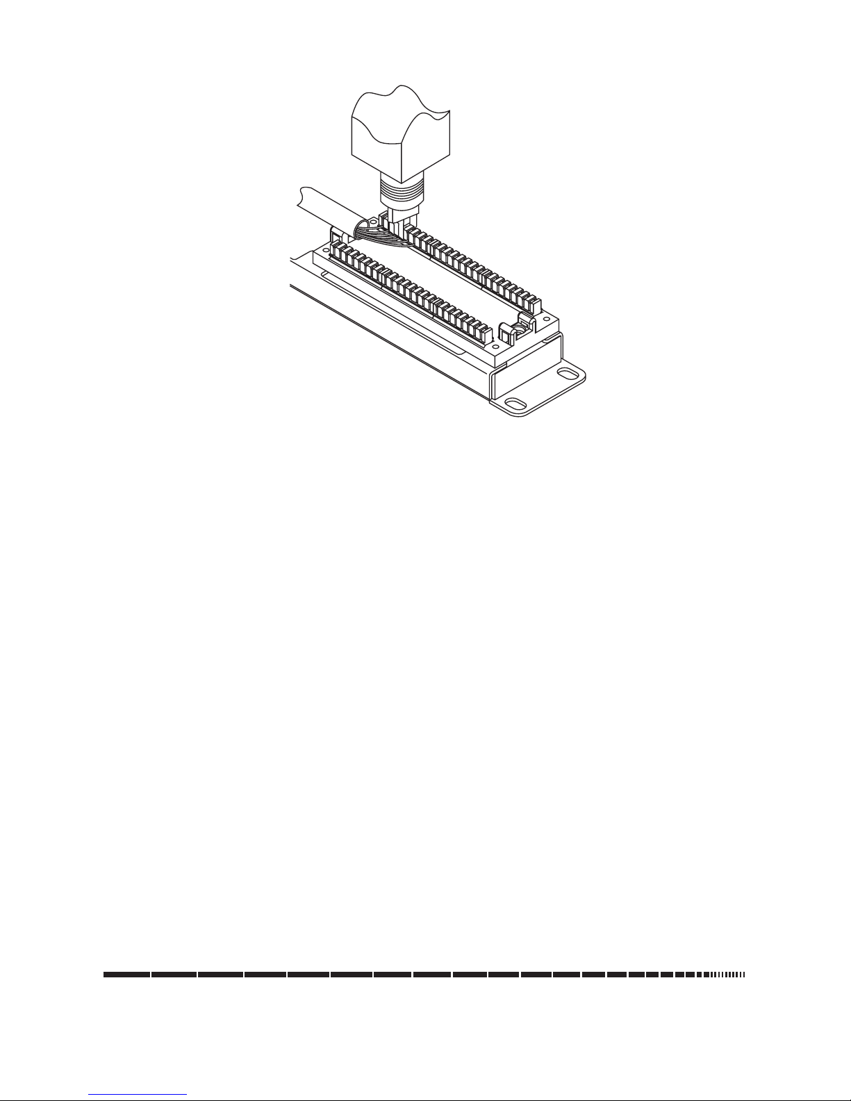
Figure 3. Terminating the wire conductors.
NOTE: For best performance, keep the untwisted part of the wire less than 0.5 inches (1.3 cm)
long.
Using a punchdown tool, terminate each wire. Push the 110 punchdown tool to the edge
of the 110 connector to trim the conductors. See Figure 3.
4. Optional: Place the stuffer caps on the terminated 110 blocks for added strain relief.
5. Finally, connect the patch cord. Plug the patch cord into the patch panel, then connect it
to the network equipment.
Installation is complete.
TRADEMARKS USED IN THIS MANUAL
Black Box and the Double Diamond logo are registered trademarks of BB Technologies,
Inc.
UL is a registered trademark of Underwriters Laboratories, Inc.
All other trademarks mentioned in this manual are acknowledged to be the property of the
trademark owners.
Page 2
CUSTOMER
SUPPORT
INFORMATION
Order toll-free in the U.S.: Call 877-877-BBOX (outside U.S. call 724-746-5500)
FREE technical support 24 hours a day, 7 days a week: Call 724-746-5500 or fax 724-746-0746
Mailing address: Black Box Corporation, 1000 Park Drive, Lawrence, PA 15055-1018
Web site: www.blackbox.com • E-mail: info@blackbox.com
NOVEMBER 2008
JPM624A
JPM648A
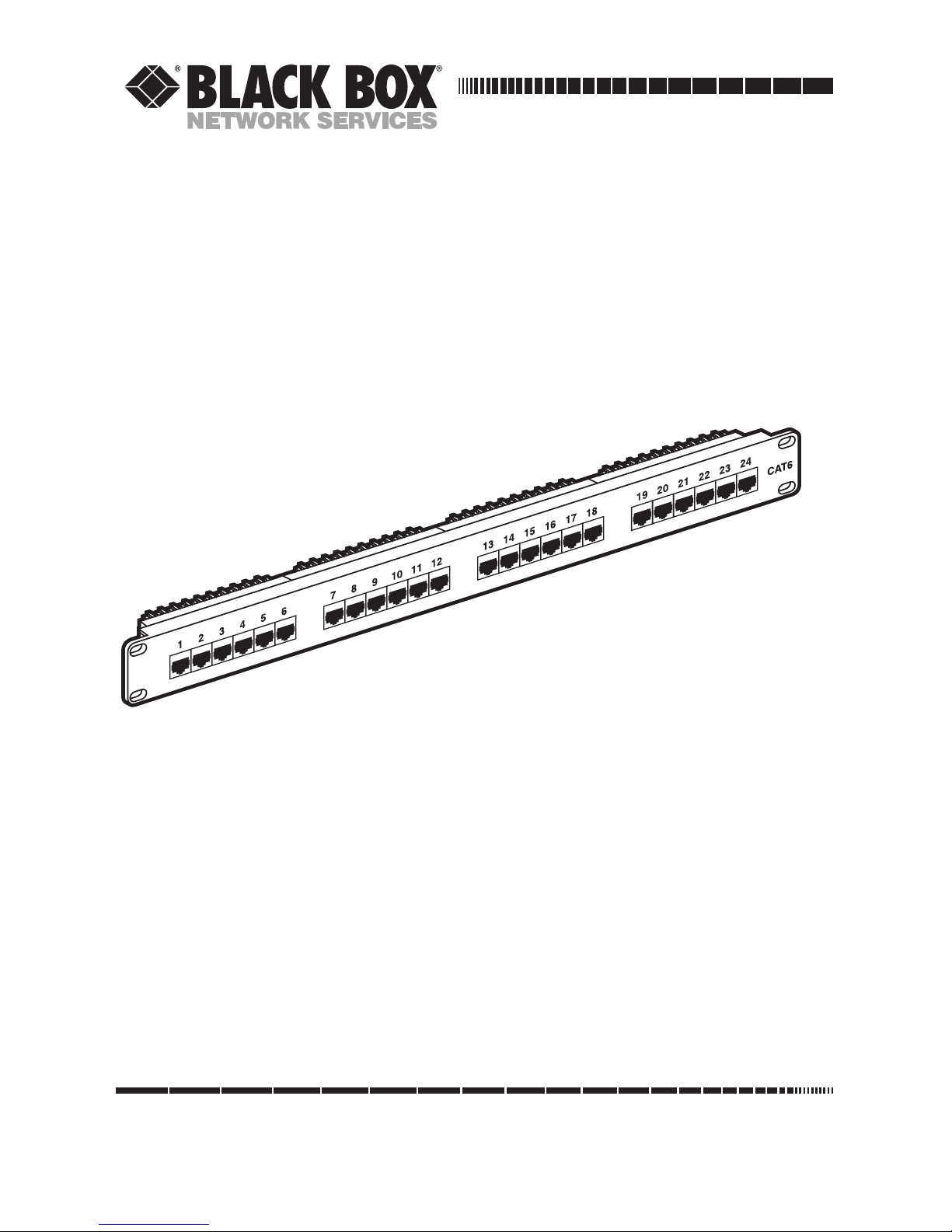
CAT6 Patch Panels
Page 3

2
CAT6 Patch Panels
Introduction
Use our CAT6 Patch Panels to consolidate cabling in wiring closets. These sturdy
panels meet Category 6 performance requirements, and their universal wiring
enables you to terminate each cable to either T568A or T568B wiring schemes.
Simply follow the color-coded guides on the panel; they identify the sequence of
cable pair terminations.
You should have received the following items:
• (1) CAT6 Patch Panel
• (8) or (16) cable ties
• (4) 10-32 cuphead screws
• (4) 12-24 cuphead screws
• (1) bag of stuffer caps
• This user's manual
If anything is missing or damaged, please contact Black Box at 724-746-5500.
You will also need a punchdown tool to terminate the horizontal cable to the patch
panel. The punchdown tool is not included with your patch panel.
Specifications
Standards: T568A and T568B
Connectors: JPM624A: (24) RJ-45, (24) 4-pair 110 punchdown;
JPM648A: (48) RJ-45, (48) 4-pair 110 punchdown
Electrical: Insulation Resistance: 500 MΩ;
Dielectric Withstanding Voltage: 1000V;
DC Current Rating: 1.5 Amps;
DC Resistance: 0.1 Ω;
Contact Resistance: 20 mΩ
Page 4

3
CAT6 Patch Panels
Material: High-impact UL® 94V-2 resin;
Spring wire: Phosphor bronze 5100W temper wire,
50-microinch gold over 100-microinch nickel undercoat;
IDC plastic: High-impact UL® 94V-2 resin;
IDC contact: Phosphor bronze tin over 60-microinch nickel
undercoat
Physical Characteristics: Insertion life: 750 mating cycles with FCC-
compliant RJ-45 plug;
IDC durability: 200 termination cycles;
Contact compatibility: Accommodates 22-24 AWG solid;
Operating temperature range: +14 to +140˚F (-10 to +60˚C)
Storage temperature range: -40 to +154˚F (-40 to 68˚C)
Humidity: 10% – 90%, relative
Size: JPM624A: 1.75"H (1U) x 19"W x 1.4"D (4.4 x 48.3 x 3.6 cm);
JPM648A: 3.5"H (2U) x 19"W x 1.4"D (8.9 x 48.3 x 3.6 cm)
Weight: JPM624A: 1.4 lb. (0.6 kg);
JPM628A: 2.5 lb. (1.1 kg)
Installation
1. Use the correct set of supplied screws on each of the four corners of the patch panel
and tighten them securely. If necessary, use a screwdriver to tighten each screw.
2. Prepare the cable by stripping about 2 inches (5.1 cm) of the cable jacket. Be careful
not to damage the twisted wire!
3. Next, punch down the cable. Place each wire pair next to the appropriate wiring color/
label. Refer to Figures 1 and 2 for T568A and T568B color codes.
Figure 1. Color codes on
the T568A side of the
wiring label.
Figure 2. Color codes on
the T568B side of the
wiring label
 Loading...