

Page 1
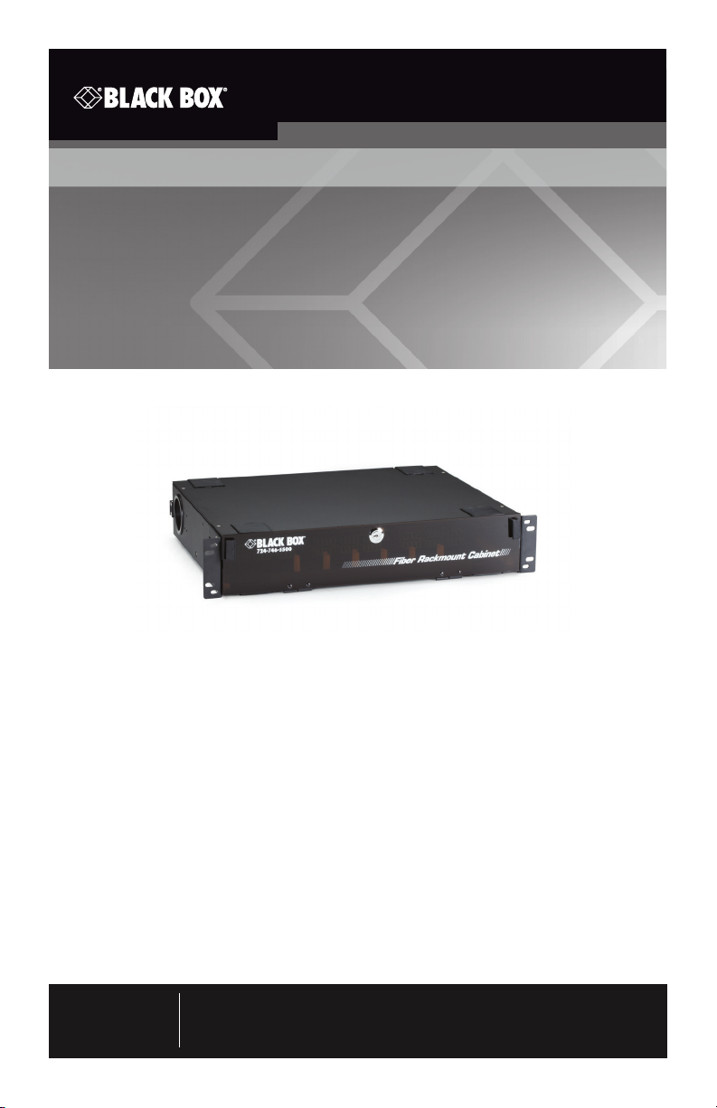
Fiber Rackmount Cabinet
Fits in a 19" or 23" rack, and supports
6 adapter panels or LGX cassettes.
JPM 418A- R5
Customer
Support
Information
Order toll-free in the U.S.: C all 877-877-BBOX (outside U. S. call 724-746 -5500)
FREE technical suppor t 24 hours a day, 7 days a week: C all 724-746-5500 or fax
724-746-0746 • Mailing address: Black Box Corporation, 100 0 Park Drive, Lawrence,
PA 15055-1018 • Web site: www.blackbox.com • E-mail: info@ blackbox.com
Page 2

Fiber Rackmount Cabinet
1. Specifications
Construction 16-gauge, cold-rolled steel
Finish Black powder coat
Dimensions Without rackmount ears: 3.5"H (2U) x 17"W x 13.8"D
(8.9 x 43.2 x 35.1 cm);
With rackmount ears: 3.5"H (2U) x 19"W x 13.8"D
(8.9 x 48.3 x 35.1 cm)
Weight 16.5 lb. (7.5 kg)
2. Overview
2.1 Introduction
The JPM418A-R5 is 2U high, fits in a 19" or 23" rack, and supports 6 adapter
panels or LGX Cassettes. Depending upon the number of fiber ports on the
adapter panel or cassette, you can have up to 144 fiber optic connections
in this rackmount enclosure. It supports standard fiber adapter panels or fiber
cassettes, depending upon the installer application.
The fiber rackmount cabinets are constructed of 16-gauge cold-rolled steel, which
is compact and rugged enough for many commercial applications. Its black
powder-coated finish provides a professional look for any data center and it‘s also
corrosion resistant. The cabinet has a front PLEXIGLAS
a front cable management bar and several entry/exit holes, cable distribution
rings, and Kevlar® clamps to support the installer’s needs. Sold separately, this
enclosure can support up to 4 splice trays inside the chassis. One splice tray can
accept up to 12 single-mode fiber splices.
®
locking door, a rear door,
2.2 What’s Included
Your package should include the following items. If anything is missing or
damaged, contact Black Box Technical Support at 724-746-5500.
• Fiber Rackmount Cabinet
• (4) 12-24 cuphead screws
• (4) 10-32 cup-head screws
• (30) 3" (7.6-cm) cable ties
• (4) 4" (10.2-cm) cable ties
• (6) rectangular plastic cable holders
Page 2
724-746-5500 | blackbox.com
Page 3

Fiber Rackmount Cabinet
• (2) pairs of black spool rings
• (1) “DANGER” sticker
• (1) locking PLEXIGLAS® door
• (2) mounting brackets
• (4) silver screws for mounting brackets
• (4) washers for mounting brackets
• (1) set of keys
• (1) identification label sticker
• This user’s manual
3. Installation
1. Attach the two mounting brackets to the cabinet, and secure them with the
four silver screws and four washers.
NOTES:
Choose front or center mounting, depending upon your application.
Choose 19" or 23" mounting by flipping the mounting brackets.
2. Using the 10-32 or 12-24 cuphead screws supplied, mount the Fiber Rackmount
enclosure to your cabinet.
3. Next, install the enclosure’s PLEXIGLAS locking front door. It attaches to the
enclosure at the bottom by the piano hinge. Then flip the door upward and use
the two plungers on each side to lock.
NOTE: If you require front patch cable management, install the rectangle plastic
holders on the front of the internal tray.
Installing Fiber in the Chassis
The installer can use Fiber Adapter Panels or LGX style cassettes in this chassis or a
combination of both. Typically, distribution cable is used with fiber adapter panels
or MTP® MPO-style connectors fiber trunk assembles are used for LGX cassettes.
LGX Style Cassettes
1. Open the front PLEXIGLAS door and slide the internal tray forward.
2. On an LGX-style cassette, pull back the two buttons for installation and choose
a location on the internal bracket where you want to install the cassette.
3. Load up to 6 LGX cassettes in the chassis depending upon your application.
724-746-5500 | blackbox.com
Page 3
Page 4

Fiber Rackmount Cabinet
4. Open the rear metal door with the two thumbscrews and let it hang
downward.
5. Connect the MTP MPO-style connectors trunk assembles to the cassette from
the rear of the chassis.
NOTE: Because of amount of fiber stands this enclosure can support, be sure to fit
your MTP MPO-style fiber connectors trunk assemblies to the cassette from
the rear.
6. Organize your trunk assemblies with the supplied cable ties.
7. Attach the identification label sticker to the rear door on the inside of the
cabinet.
Distribution Style Fiber Cable
1. Open the front PLEXIGLAS door and slide the internal tray forward.
2. On the fiber adapter panels, pull back the two buttons for installation and
choose a location on the internal bracket where you want to install them.
3. Load up to 6 fiber adapter panels in the chassis depending upon your
application.
4. Next, open the rear metal door with the two thumbscrews and let it hang
downward.
5. Route multi-strand distribution fiber cable (not included) through the
rectangular openings on the cabinet’s top or bottom, or through the rubber
grommets on the side.
6. Use the Kevlar clamp to secure the multi-strand distribution fiber to the cabinet.
Loosen the Kevlar clamp’s two screws and wrap the cable’s Kevlar yarn around
the clamp. Tighten the screws to secure the multi-strand distribution fiber to
the cabinet.
NOTE: The Kevlar clamp mounts on the left or right back of the cabinet.
7. Terminate the fiber optic connectors on the multi-strand distribution fiber cable,
or make the splice as needed. (See Figures 1 and 2 for a typical cable
installation.) Connect the fiber cable termination to the rear of the fiber adapters panel.
NOTE: If you need to make fiber splicing inside the chassis, use the Fiber Splice
Tray (sold separately).
8. Organize your trunk assemblies with the cable ties supplied and close the rear
door.
9. Attach the identification label sticker to the inside rear door of the cabinet.
Page 4
724-746-5500 | blackbox.com
Page 5
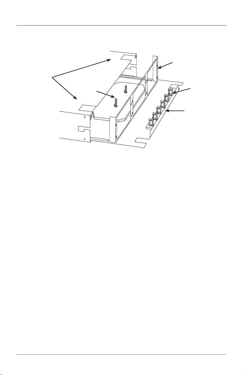
Rectangular
openings
Kevlar clamp
installed on the side
rear corner
Figure 1. Fiber Rackmount Cabinet with tray pulled out.
Splice tray
(optional)
Fiber Rackmount Cabinet
Install the fiber
adapters or
cassettes here
Rectangular cable
holders
Inside
tray
724-746-5500 | blackbox.com
Page 5
Page 6
Fiber Rackmount Cabinet
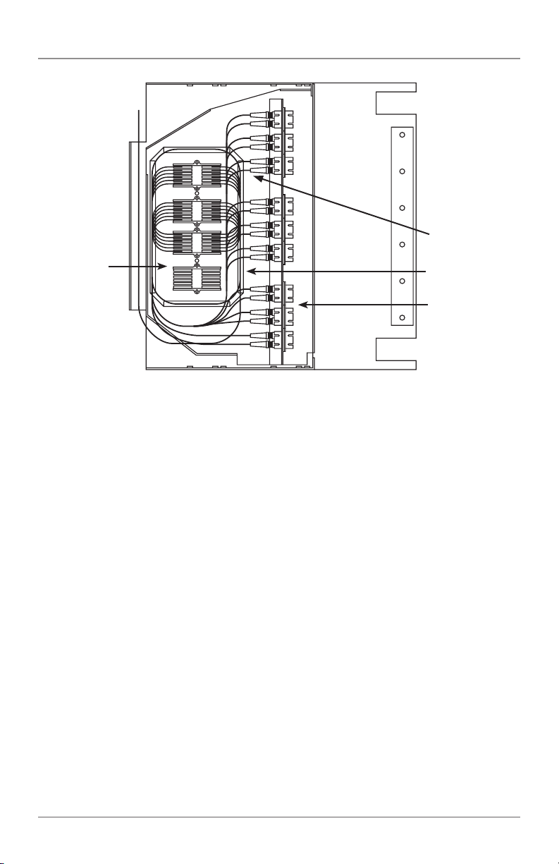
Fiber optic
Splice tray
(JPM440A, not
included)
Figure 2. The JPM418A-R5 with three fiber adapter panels visible (up to three
more can be stacked beneath the visible ones, for a total of 6 adapter panels).
The fiber cable is routed through the splice tray,
then terminated via the fiber optic connectors.
connectors
Fiber optic
cable
Fiber adapter panel
with 6 fiber optic
connectors installed
Page 6
724-746-5500 | blackbox.com
Page 7

NOTES
724-746-5500 | blackbox.com
Page 7
Page 8
Black Box Tech Support: FREE! Live. 24/7.
Tech support the
way it should be.
Great tech support is just 60 seconds away at
724-746-5500 or blackbox.com.
About Black Box
Black Box provides an extensive range of networking and infrastructure products.
You’ll find everything from cabinets and racks and power and surge protection
products to media converters and Ethernet switches all supported by free, live 24/7
Tech Support available in 60 seconds or less.
© Copyright 2014. Black Box Corporation. All rights reserved. Black Box® and the Double Diamond logo
are registered trademarks of BB Technologies, Inc. Kevlar
and Company. PLEXIGL AS
Conec Ltd. Any third -party trademarks appearing in this manual are acknowledged to be the property of their
respective owners.
JPM418A-R5, version 1
®
is a registered trademark of Roehm GmbH & CO. MTP is a registered trademark of US
®
is a registered trademark of E. I. du Pont de Nemours
724-746-5500 | blackbox.com
 Loading...