

Page 1
USER MANUAL
JPM 401A-R2
FIBER
WALLMOUNT
CABINET
24/7 TECHNICAL SUPPORT AT 1.877.877.2269 OR VISIT BLACKBOX.COM
Page 2

NEED HELP?
LEAV E TH E TEC H TO US
LIVE 24/7
TABLE OF CONTENTS
TECHNICAL
SUPPORT
1. 8 7 7. 8 7 7. 2 2 6 9
1. O V E R V I E W ................................................................................................................................................................................................. 3
1.1 Introduction .......................................................................................................................................................................................................... 3
1.2 What’s Included ................................................................................................................................................................................................... 3
2. I N S TA L L AT I O N ......................................................................................................................................................................................... 4
2.1 Installing the Cabinet and Cable ........................................................................................................................................................................ 4
2.2 Installing the Splice Trays (Optional) ................................................................................................................................................................. 4
2.3 Preparing the Cable ............................................................................................................................................................................................ 5
2.4 Routing the Fiber Patch Cables ......................................................................................................................................................................... 5
APPENDIX: DISCLAIMER/TRADEMARKS .................................................................................................................................................. 6
A.1 Disclaimer ............................................................................................................................................................................................................ 6
A.2 Trademarks Used in this Manual ....................................................................................................................................................................... 6
2
1. 87 7.8 7 7. 2 26 9 BLACKBOX.COM
Page 3

NEED HELP?
LEAV E TH E TEC H TO US
LIVE 24/7
CHAPTER 1: OVERVIEW
TECHNICAL
SUPPORT
1. 8 7 7. 8 7 7. 2 2 6 9
1.1 INTRODUCTION
This Fiber Wall Cabinet is used to extend indoor fiber optic distribution cable runs out from the data center to a remote wallmount area
in your building. The fiber wallmount enclosure allows the incoming bulk fiber optic distribution cable to break out and terminate to fiber
adapter panels in the enclosure where the user can use fiber duplex cable to connect to your equipment.
The fiber optic open style wall cabinet is perfect for non-secured fiber cabling. The open cabinet has one large door that covers both
internal compartments. The left internal compartment is the technician side and the right internal compartment is the user’s side. This
enclosure can accept up to four fiber adapter panels.
The cabinet’s rugged metallic housing is made of heavy-gauge steel with a powder coat finish. Bulk fiber cabling can enter the enclosure
from the top left or bottom left grommet opening. The rubber grommet is a thin membrane seal that prevents dust from settling inside.
In addition, the enclosure can accommodate an internal splice tray for fusion or mechanical splicing.
1.2 WHAT’S INCLUDED
Your package should include the following items. If anything is missing or damaged, please contact Black Box at 877-877-2269
or [email protected].
(1) Fiber Wall Cabinet, 4-Adapter Panel
(1) Warning label
(6) 1” (2.5-cm) stick-on rectangular cable holders
(4) Mounting screws
(30) 3” (7.6-cm) cable ties
(4) 4” (10.2-cm) cable ties
(1) cable management sticker
(1) set of ID labels (1, 2, 3, 4)
(2) semicircular cable holding rings (installed)
(1) set of replacement buttons
1. 87 7.8 7 7. 2 26 9 BLACKBOX.COM
3
Page 4
NEED HELP?
LEAV E TH E TEC H TO US
LIVE 24/7
CH AP TE R 2: IN STA LL ATI ON
2.1 INSTALLING THE CABINET AND CABLE
Follow these steps:
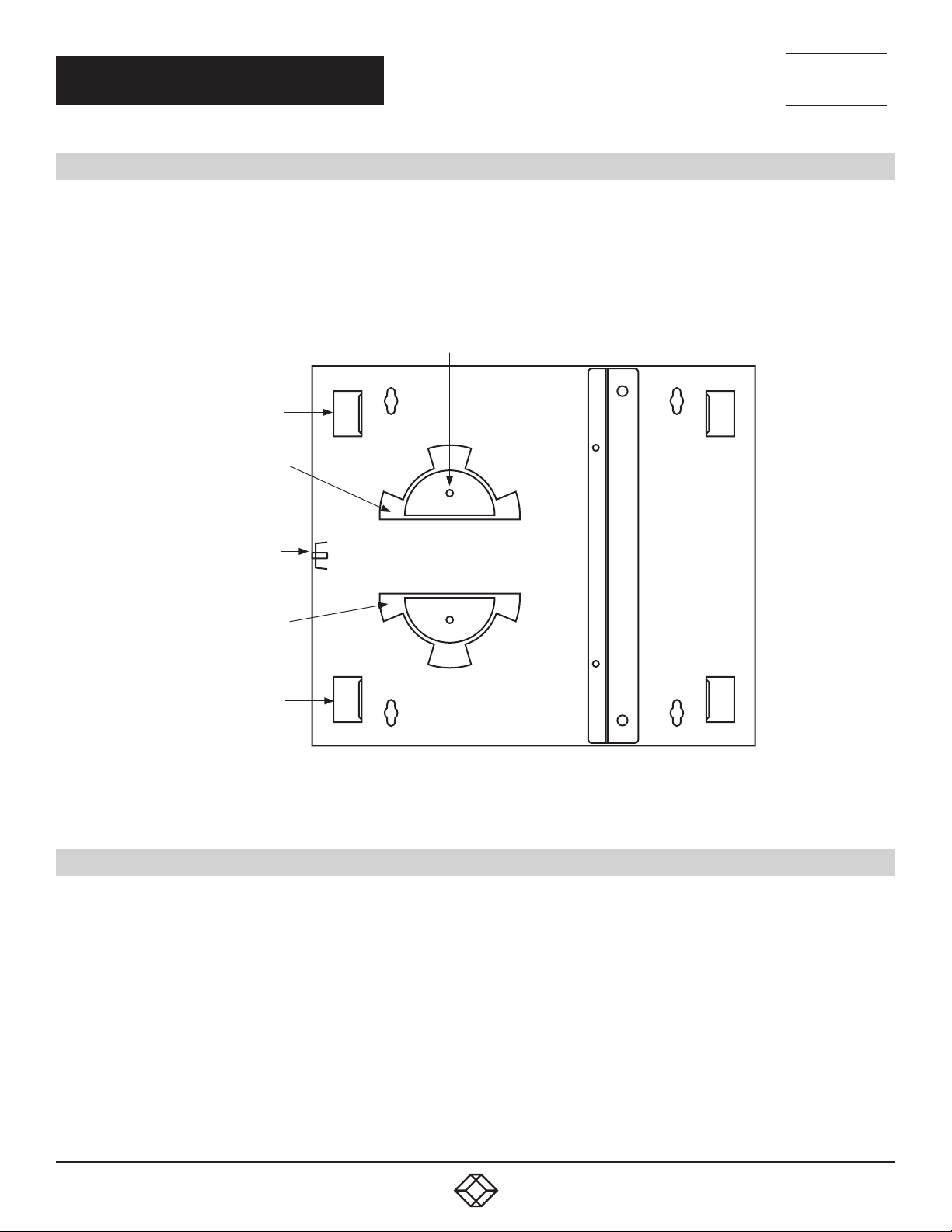
1. Open the cabinet’s doors and use a screwdriver to attach the cabinet to a wall with the four included mounting screws. Or, use your
own hardware to mount the cabinet on a block wall.
2. Bring in your bulk fiber cable in either the cabinet’s top left or bottom left on the enclosure.
3. Strip back the cable jacket on the incoming bulk fiber cable and use the cable ties to secure to the enclosure at the internal mounting
points. Make sure you anchor the fiber cable with the Kevlar yarn to the Kevlar clamp on the enclosure.
Wing nuts
Cable internal
mounting points
Semicircular
cable holding
ring
TECHNICAL
SUPPORT
1. 8 7 7. 8 7 7. 2 2 6 9
Kevlar clamp
Semicircular
cable holding
ring
Cable internal
mounting points
Compartment plate
for fiber adapters
Technician’s side
FIGURE 2-1. THE JPM401A-R2 CABINET’S INSIDE VIEW
2.2 INSTALLING THE SPLICE TRAYS (OPTIONAL)
1. Unfasten the two wing head nuts inside the cabinet. Remove the semi-circular take-up rings.
2. Place the splice tray through the threaded studs.
3. Make your fiber splices and re-install the tray cover.
4. Re-fasten the wing head nuts.
User’s side
4
1. 87 7.8 7 7. 2 26 9 BLACKBOX.COM
Page 5

NEED HELP?
LEAV E TH E TEC H TO US
LIVE 24/7
CH AP TE R 2: IN STA LL ATI ON
2.3 PREPARING THE CABLE
1. After the incoming bulk fiber cable is secured to the enclosure, wrap the excess individual fiber strands around the semi-circular rings.
2. Install the fiber adapter panels in the wallmount fiber enclosure.
3. Terminate each fiber strand with the fiber optic connector and attach it to the fiber adapter panel.
2.4 ROUTING THE FIBER PATCH CABLES
1. After all the individual strands are terminated and connected to the fiber adapter panels, use fiber patch cables and connect to the user
side of the adapter panels.
2. After the patch cords are terminated and connected to the fiber adapter panel, use the cable ties and stick-on rectangular cable
holders to organize your work.
TECHNICAL
SUPPORT
1. 8 7 7. 8 7 7. 2 2 6 9
1. 87 7.8 7 7. 2 26 9 BLACKBOX.COM
5
Page 6

NEED HELP?
LEAV E TH E TEC H TO US
LIVE 24/7
APPENDIX: DISCLAIMER/TRADEMARKS
TECHNICAL
SUPPORT
1. 8 7 7. 8 7 7. 2 2 6 9
A.1 DISCLAIMER
Black Box Corporation shall not be liable for damages of any kind, including, but not limited to, punitive, consequential or cost of cover
damages, resulting from any errors in the product information or specifications set forth in this document and Black Box Corporation
may revise this document at any time without notice.
A.2 TRADEMARKS USED IN THIS MANUAL
Black Box and the Black Box logo type and mark are registered trademarks of Black Box Corporation.
Any other trademarks mentioned in this manual are acknowledged to be the property of the trademark owners.
6
1. 87 7.8 7 7. 2 26 9 BLACKBOX.COM
Page 7

NOTES
__________________________________________________________________________________________________
__________________________________________________________________________________________________
__________________________________________________________________________________________________
__________________________________________________________________________________________________
_
_________________________________________________________________________________________________
__________________________________________________________________________________________________
NEED HELP?
LEAV E TH E TEC H TO US
LIVE 24/7
TECHNICAL
SUPPORT
1. 8 7 7. 8 7 7. 2 2 6 9
__________________________________________________________________________________________________\
__________________________________________________________________________________________________
__________________________________________________________________________________________________
__________________________________________________________________________________________________
__________________________________________________________________________________________________
_________________________________________________________________________________________________
__________________________________________________________________________________________________
__________________________________________________________________________________________________
__________________________________________________________________________________________________
__________________________________________________________________________________________________
__________________________________________________________________________________________________
__________________________________________________________________________________________________
1. 87 7.8 7 7. 2 26 9 BLACKBOX.COM
7
Page 8

NEED HELP?
LEAVE THE TECH TO US
LIVE 24/7
TECHNICAL
SUPPORT
1.87 7. 8 7 7. 22 6 9
© COPYRIGHT 2018. BLACK BOX CORPORATION. ALL RIGHTS RESERVED.
JPM401A-R2_USER_RE V1.PDF
 Loading...