

Page 1
USER MANUAL
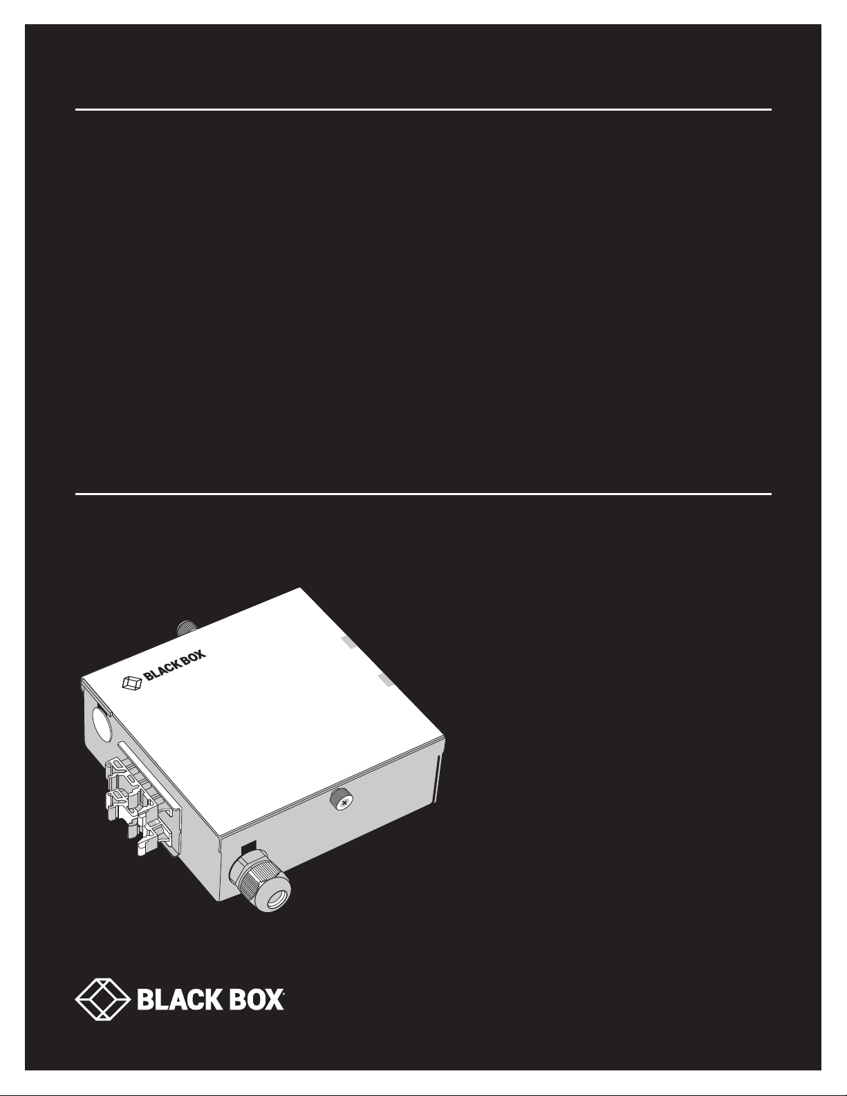
JPM397A, JPM398A
DIN RAIL
FIBER
ENCLOSURE
24/7 TECHNICAL SUPPORT AT 1.877.877.2269 OR VISIT BLACKBOX.COM
Page 2

NEED HELP?
LEAV E TH E TEC H TO US
LIVE 24/7
TABLE OF CONTENTS
TECHNICAL
SUPPORT
1. 8 7 7. 8 7 7. 2 2 69
1. SPECIFICATIONS ........................................................................................................................................................................... 3
2. OVERVIE W ...................................................................................................................................................................................... 4
2.1 Description ................................................................................................................................................................................................ 4
2.2 What’s Included ........................................................................................................................................................................................4
2.3 Part Numbers ...........................................................................................................................................................................................4
3. PRE-I NSTALLATION ...................................................................................................................................................................... 5
3.1 STEP 1: Enclosure Mounting ...................................................................................................................................................................5
STEP 1A: Optional Mounting Solutions ................................................................................................................................................................... 6
3.2 STEP 2: Bulk Fiber Cable Entry ...............................................................................................................................................................8
4. I NSTALLATION ............................................................................................................................................................................ 10
4.1 STEP 1: Mounting the Enclosure to the DIN Rail .................................................................................................................................. 10
4.2 STEP 2: Cabling and Securing the Bulk Fiber to the Enclosure .........................................................................................................10
4.3 STEP 3: Terminating the Fiber Cable .................................................................................................................................................... 11
2
1. 87 7. 8 7 7. 2 26 9 BL ACK BOX .COM
Page 3

CHAPTER 1: SPECIFICATIONS
TABLE 1. JPM398A SPECIFICATIONS
SPECIFICATION DESCRIPTION
Dimensions 2.01" H x 5.31" W x 5.51" D (5.1 x 13.5 x 14 cm)
Weight 1.15 lb. (0.52 kg)
Metal Thickness 18-gauge (1.0 mm)
Color Black
Cable Grommet Range 4.0 mm to 8.0 mm
Fiber Adapter Ports One
TABLE 2. JPM397A SPECIFICATIONS
SPECIFICATION DESCRIPTION
Dimensions 3.93" H x 5.31" W x 5.51" D (10.0 x 13.5 x 14 cm)
Weight 2.0 lb. (0.907 kg)
Metal Thickness 18-gauge (1.0 mm)
Color Black
Cable Grommet Range 4.0 mm to 8.0 mm
Fiber Adapter Ports Two
NEED HELP?
LEAV E TH E TEC H TO US
LIVE 24/7
TECHNICAL
SUPPORT
1. 8 7 7. 8 7 7. 2 2 69
1. 87 7. 8 7 7. 2 26 9 BL ACK BOX .COM
3
Page 4

NEED HELP?
LEAV E TH E TEC H TO US
LIVE 24/7
CHAPTER 2: OVERVIEW
2.1 DESCRIPTION
This inexpensive and very flexible DIN Rail Fiber Enclosure is an excellent choice when you need to run fiber terminations out on
an open external wall or in an open manufacturing floor environment. The DIN Rail Fiber Enclosure is small and made of steel.
It supports either one or two LGX fiber adapter panels with a side door that uses thumbscrews for easy access inside of the
enclosure. There are also many DIN rail mounting options around the enclosure, along with three bulk fiber points of entry, when
combined make this enclosure extremely flexible.
2.2 WHAT’S INCLUDED
Your package should include the following items for either the 1 or 2 port DIN Rail Fiber enclosure. If anything is missing or
damaged, contact Black Box Technical Support at 877-877-2269 or info @blackbox.com.
(1) DIN Rail Fiber Enclosure
(4) 1” x ½” stick-on cable organizers
(5) 4-inch cable ties
(10) 3-inch cable ties
(1) “L”-shaped rackmount bracket
TECHNICAL
SUPPORT
1. 8 7 7. 8 7 7. 2 2 69
4
1. 87 7. 8 7 7. 2 26 9 BL ACK BOX .COM
Page 5
NEED HELP?
LEAV E TH E TEC H TO US
LIVE 24/7
CH APTER 3: PRE-INSTAL L ATION
TECHNICAL
SUPPORT
1. 8 7 7. 8 7 7. 2 2 69
The pre-installation steps can be used for both the 1 and 2 ports DIN Rail enclosures. For illustration, we are only showing the 1 port
DIN Rail enclosure.
3.1 STEP 1: ENCLOSURE MOUNTING
First, determine where you wish to mount the enclosure. The DIN Rail Fiber Enclosures have several possible DIN rail mounting
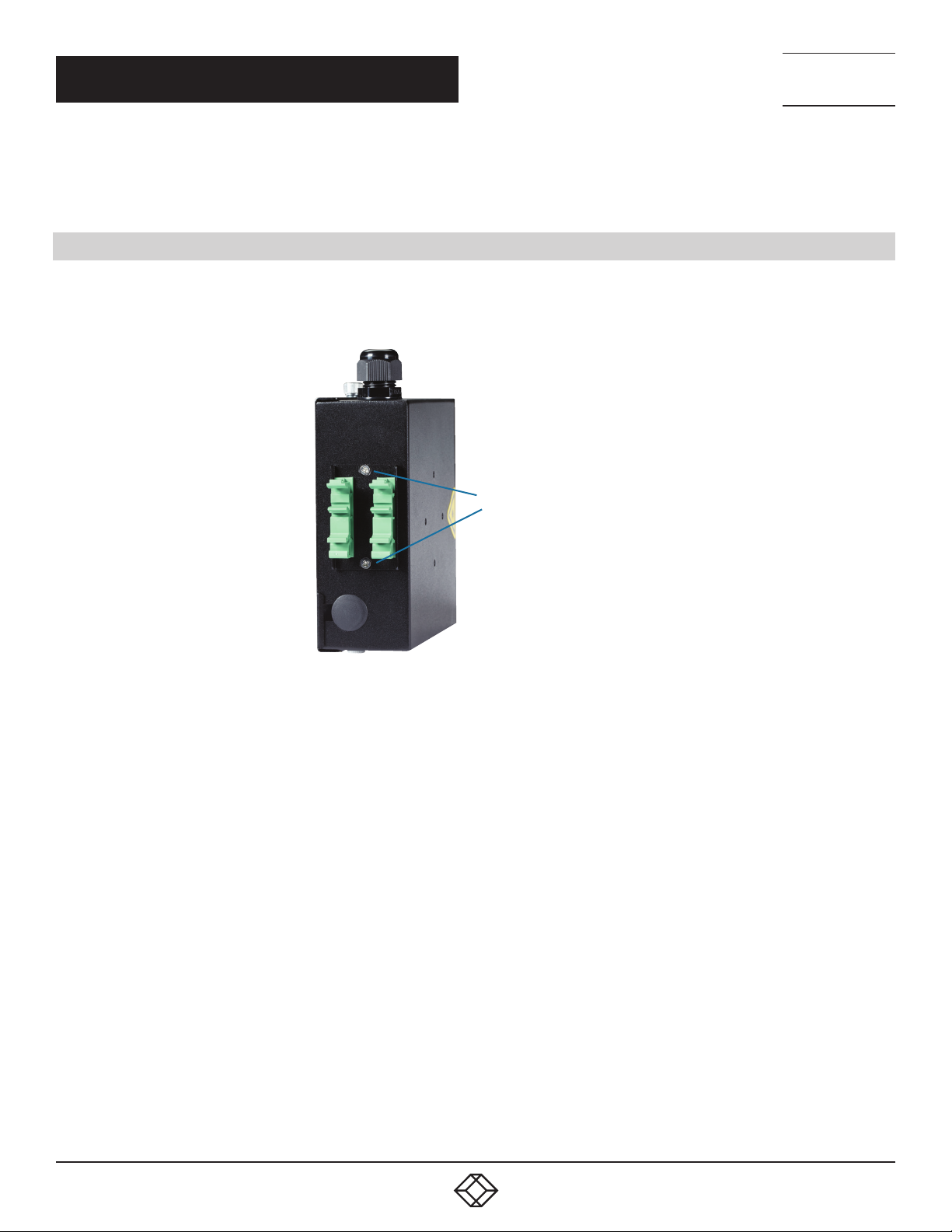
options that the user can select. From the factory, the DIN rail bracket is located on the rear of the enclosure (see photo).
(2) screws on the
DIN rail mounting plate
FIGURE 3-1. DIN RAIL BRACKET ON THE ENCLOSURE
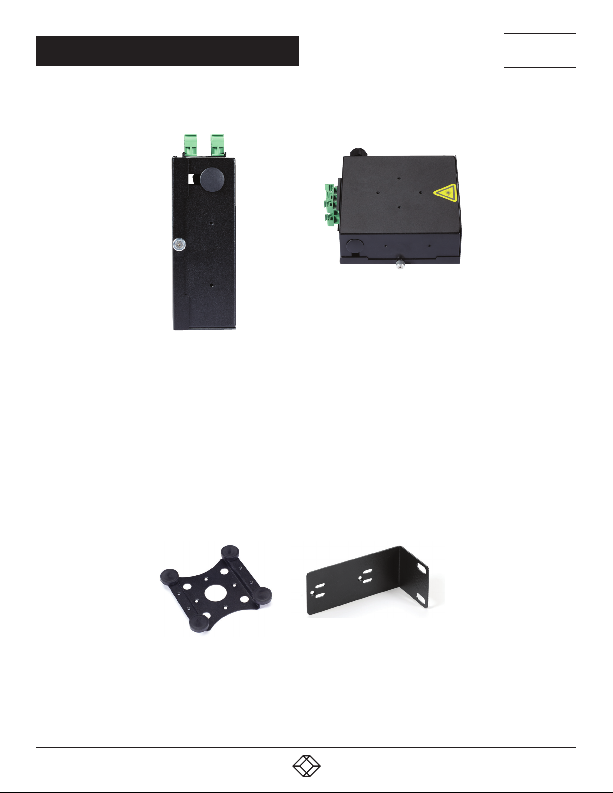
But, to mount the DIN Rail Fiber Enclosure in alternate locations, remove the screws on the DIN Rail mount plate and relocate it to
the new location. The alternate other mounting locations are on the top and bottom of the enclosure near the thumbscrews of the
door plate and the back side of the enclosure.
1. 87 7. 8 7 7. 2 26 9 BL ACK BOX .COM
5
Page 6
CH APTER 3: PRE-INSTALLATION
Back side
mounting locations
NEED HELP?
LEAV E TH E TEC H TO US
LIVE 24/7
TECHNICAL
SUPPORT
1. 8 7 7. 8 7 7. 2 2 69
Top and bottom
mounting locations
FIGURE 3-2. TOP AND BOT TOM AND BACK SIDE MOUNTING LOCATIONS
STEP 1A: OPTIONAL MOUNTING SOLUTIONS
The DIN Rail Fiber Enclosure has several other optional mounting solutions. There is an optional Magnetic Bracket (sold separately,
part number ACC-MAGBRKT) and an “L” shaped Adapter bracket (included with the DIN Rail Enclosure) that can be used for the other
non-DIN rail mounting installations. (See Photo below) These optional mounting solutions are supported on either the one or two
port Din Rail Fiber Enclosure.
included
part number
ACC-MAGBRKT
FIGURE 3-3. OPTIONAL MAGNETIC BRACKET AND “L”-SHAPED BR ACKET
6
1. 87 7. 8 7 7. 2 26 9 BL ACK BOX .COM
Page 7
NEED HELP?
LEAV E TH E TEC H TO US
LIVE 24/7
CH APTER 3: PRE-INSTALLATION
To use either one of these optional mounting solutions on your DIN Rail Fiber Enclosure, remove the green DIN Rail bracket from
the fiber enclosure. Choose either the magnetic bracket or the “L” shaped bracket for your application.
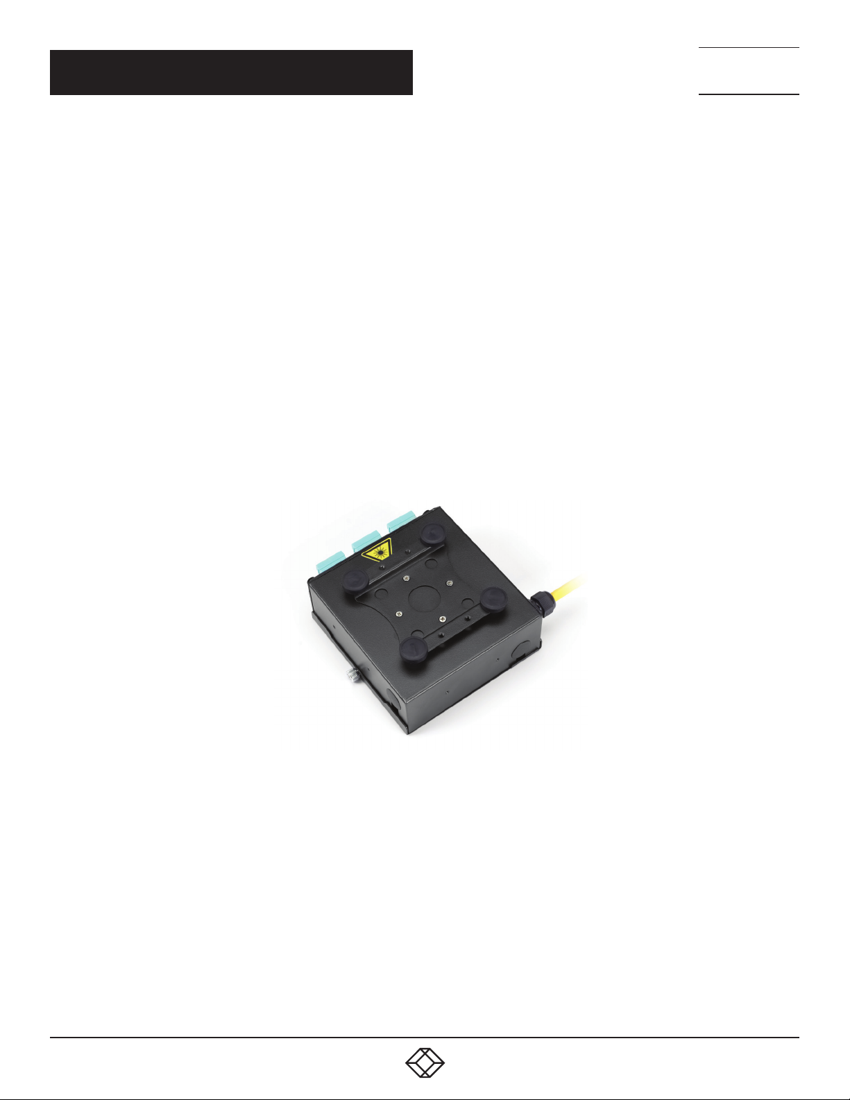
The Magnetic Bracket can be installed at the following locations on the DIN Rail Fiber Enclosure. Four screws must be used to
property mount the magnetic bracket to the enclosure.
One Port Enclosure – Only on the side for flush mounting
Two Port Enclosure – On the side for flush mounting and the rear side opposite the fiber ports
NOTE: The magnet bracket adapter uses four high-power rare earth magnets with a rubber coated base. These four magnets
together have tremendous holding power and should be used on metal surfaces where you may want to mount your DIN Rail Fiber
Enclosure.
CAUTION: Always use care when handling. Follow the precautions listed below.
Always wear safety goggles when handling large magnets.
Always wear gloves when handling magnets to prevent pinching.
Children should NEVER be allowed to play with Neodymium magnets.
WARNING: Keep magnets at least 7.9 inches (20 cm) away from devices such as sensitive electronic and storage devices,
mechanical watches, heart pacemakers, CRT monitors and televisions, credit cards, diskettes and other magnetically stored
media such as video tapes. These devices are all affected by powerful magnets.
TECHNICAL
SUPPORT
1. 8 7 7. 8 7 7. 2 2 69
FIGURE 3-4. APPLICATION #1, MAGNETIC BRACKET
The “L” Shaped Adapter Bracket can be installed at the following locations on the DIN Rail Fiber Enclosure. Two screws are used
for to correctly mount the “L” Shaped bracket to the enclosure. It has oversized cup head holes to allow the user some flexibility in
mounting to a wide range of relay racks or cabinets.
One Port Enclosure – On the side for flush mounting and the rear side opposite the fiber ports
Two Port Enclosure – On all sides of the enclosure in various locations
1. 87 7. 8 7 7. 2 26 9 BL ACK BOX .COM
7
Page 8
CH APTER 3: PRE-INSTALLATION
NOTE: The “L” Shaped Adapter Bracket will not install on the top or bottom of the one-port enclosure.
NEED HELP?
LEAV E TH E TEC H TO US
LIVE 24/7
TECHNICAL
SUPPORT
1. 8 7 7. 8 7 7. 2 2 69
FIGURE 3-5. APPLICATION #2, L-SHAPED BRACKET
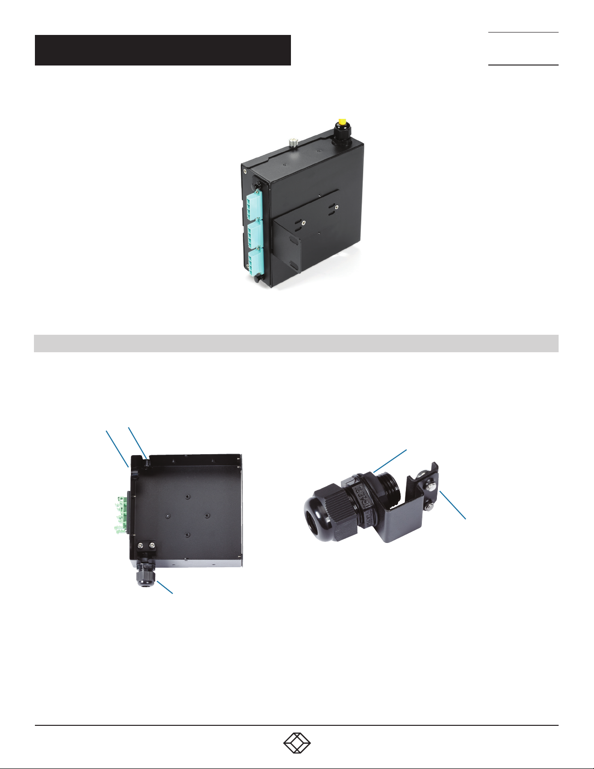
3.2 STEP 2: BULK FIBER CABLE ENTRY
There are several points of entry where the incoming bulk fiber cable can enter the enclosure. From the factory, the point of entry is
located at the bottom of the enclosure and the other access points are plugged. The bulk fiber cable is secured by a small angled
bracket with a hand-tighten grommet and Kevlar
angled bracket to another available position.
®
clamp. If an alternate bulk fiber point of entry is desired, you can relocate the
Bulk fiber entry
Grommet nut
Kevlar® clamp
Bulk fiber entry
FIGURE 3-6. BULK FIBER CABLE ENTRY LOCATIONS
8
1. 87 7. 8 7 7. 2 26 9 BL ACK BOX .COM
Page 9

CH APTER 3: PRE-INSTALLATION
To change the fiber point of entry:
1. Loosen the grommet nut and remove the angled bracket.
2. Find the new entry point and remove the plug cap and re-install the angled bracket.
3. Be sure to secure the angled bracket and re-install the plug cap in the previous location.
NOTE: Make sure that you do steps 1 and 2 first. This will make your installation easier.
NEED HELP?
LEAV E TH E TEC H TO US
LIVE 24/7
TECHNICAL
SUPPORT
1. 8 7 7. 8 7 7. 2 2 69
1. 87 7. 8 7 7. 2 26 9 BL ACK BOX .COM
9
Page 10
NEED HELP?
LEAV E TH E TEC H TO US
LIVE 24/7
CH APTER 4: INS TALL ATI ON
Now that you have made a DIN rail mounting and bulk fiber point of entry selection, you can begin to complete your installation.
Completing the installation will require mounting the enclosure to the DIN rail, cabling and securing the bulk fiber cable to the
enclosure, and making the fiber terminations.
4.1 STEP 1: MOUNTING THE ENCLOSURE TO THE DIN RAIL
1. Find a DIN rail bracket that is firmly secured to a wall.
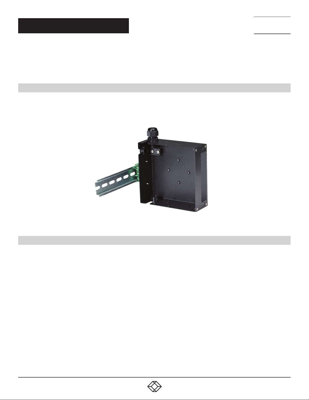
2. Snap in the enclosure to the DIN rail on the wall until you hear a click (see photo).
3. Check that both green DIN rail brackets are locked and that the enclosure is firmly mounted.
TECHNICAL
SUPPORT
1. 8 7 7. 8 7 7. 2 2 69
FIGURE 4-1. ENCLOSURE MOUNTING ON A DIN RAIL
4.2 STEP 2: CABLING AND SECURING THE BULK FIBER TO THE ENCLOSURE
Now that the enclosure is firmly mounted to the wall, you can finish the installation.
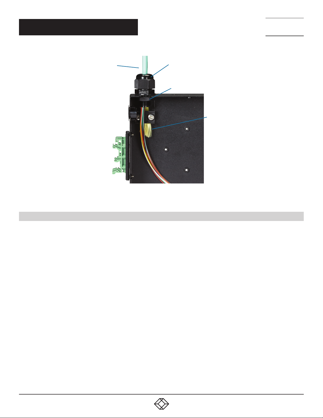
1. Remove the two screws on the Kevlar clamp and remove the large grommet nut outside the enclosure.
NOTE: Do this first (before you run bulk fiber cable in the enclosure).
2. Put the large grommet nut through the bulk fiber cable and feed the fiber cable end through the grommet on the enclosure.
3. Re-attach the large grommet nut to the grommet to firmly secure the fiber while you complete the installation. Make sure you
feed enough fiber cable through the enclosure so you can terminate the fiber connectors.
4. Next, strip the cable jacket back close to the tip of the grommet end. Trim back the Kevlar yarn so just enough is available to
firmly secure the Kevlar yarn to the clamp.
5. Attach the Kevlar yarn to the base and re-secure the 2 screws and tighten. This will hold the bulk fiber cable in the enclosure and
will not put any stress on the fiber connection inside the enclosure.
6. Repeat for any other bulk fiber cable points of entry.
10
1. 87 7. 8 7 7. 2 26 9 BL ACK BOX .COM
Page 11
CH APTER 4: INS TALL ATI ON
Bulk fiber
Big grommet nut
Grommet end tip
Kevlar yarn
NEED HELP?
LEAV E TH E TEC H TO US
LIVE 24/7
TECHNICAL
SUPPORT
1. 8 7 7. 8 7 7. 2 2 69
FIGURE 4-2. SECURING THE FIBER TO THE ENCLOSURE
4.3 STEP 3: TERMINATING THE FIBE R CABLE
Before you begin terminating the individual fiber strands, mount your fiber adapter panel to the front of the enclosure.
The DIN Rail Fiber Enclosure accepts only LGX style fiber adapter panels.
1. Install your LGX fiber adapter panel.
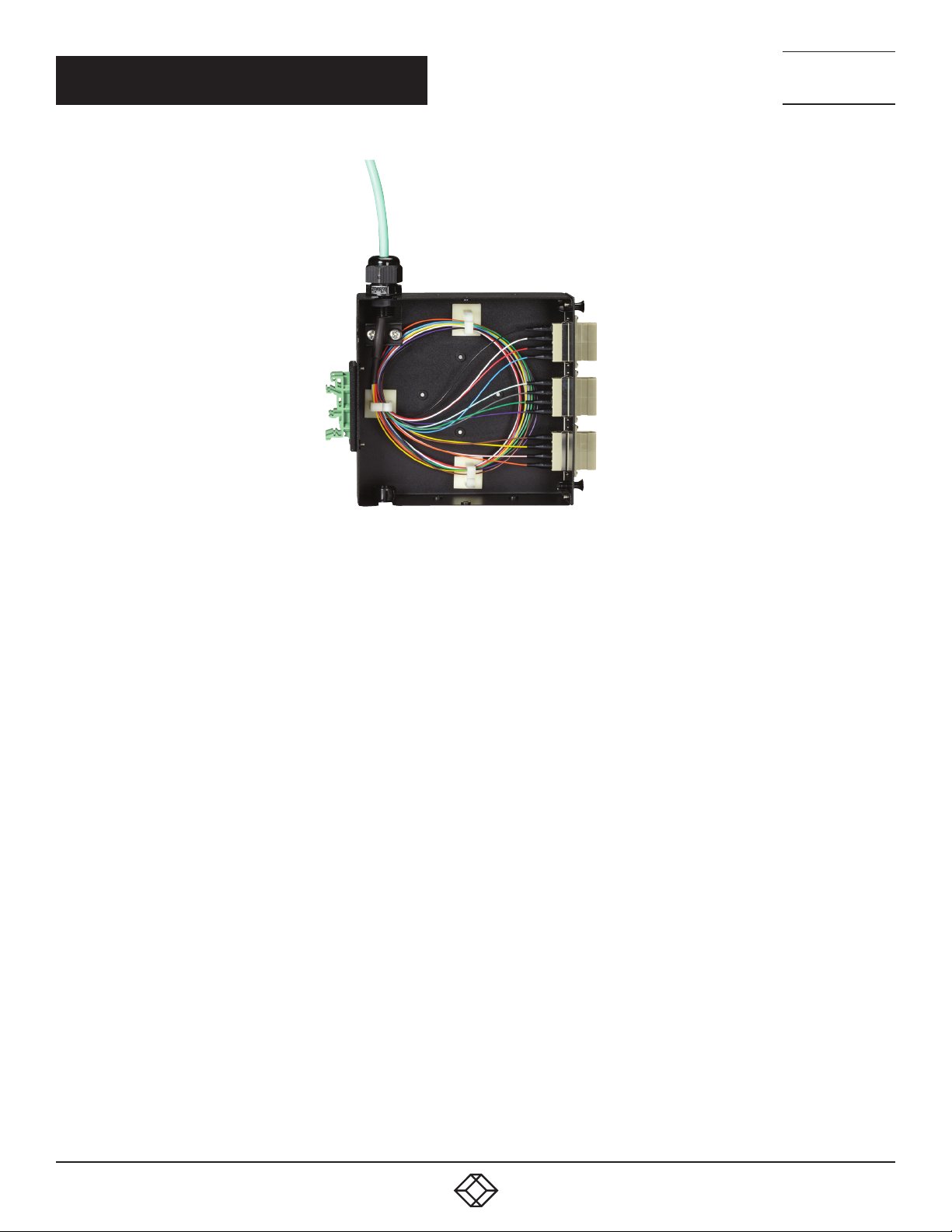
2. Begin to individually terminate each fiber strand. Make sure that you provide enough slack inside the enclosure. This is usually
done by providing a service loop.
3. Install and use the stick-on cable management organizers inside the enclosure to keep the fiber neat and manageable.
4. Terminate each fiber strand one at a time, dress the excess fiber with the stick-on cable organizers, and connect them to the
inside of the fiber adapter panel.
1. 87 7. 8 7 7. 2 26 9 BL ACK BOX .COM
11
Page 12
CH APTER 4: INS TALL ATI ON
NEED HELP?
LEAV E TH E TEC H TO US
LIVE 24/7
TECHNICAL
SUPPORT
1. 8 7 7. 8 7 7. 2 2 69
FIGURE 4-3. FIBER CABLE TERMINATED
12
1. 87 7. 8 7 7. 2 26 9 BL ACK BOX .COM
Page 13

NOTES
__________________________________________________________________________________________________
__________________________________________________________________________________________________
__________________________________________________________________________________________________
__________________________________________________________________________________________________
__________________________________________________________________________________________________
_
_________________________________________________________________________________________________
NEED HELP?
LEAV E TH E TEC H TO US
LIVE 24/7
TECHNICAL
SUPPORT
1. 8 7 7. 8 7 7. 2 2 69
__________________________________________________________________________________________________
__________________________________________________________________________________________________\
__________________________________________________________________________________________________
__________________________________________________________________________________________________
__________________________________________________________________________________________________
__________________________________________________________________________________________________
________________________________________________________________________________________________
__________________________________________________________________________________________________
__________________________________________________________________________________________________
__________________________________________________________________________________________________
__________________________________________________________________________________________________
__________________________________________________________________________________________________
1. 87 7. 8 7 7. 2 26 9 BL ACK BOX .COM
13
Page 14

NOTES
_
_________________________________________________________________________________________________
__________________________________________________________________________________________________
__________________________________________________________________________________________________\
__________________________________________________________________________________________________
__________________________________________________________________________________________________
__________________________________________________________________________________________________
NEED HELP?
LEAV E TH E TEC H TO US
LIVE 24/7
TECHNICAL
SUPPORT
1. 8 7 7. 8 7 7. 2 2 69
__________________________________________________________________________________________________
________________________________________________________________________________________________
__________________________________________________________________________________________________
__________________________________________________________________________________________________
__________________________________________________________________________________________________
__________________________________________________________________________________________________
__________________________________________________________________________________________________
_
_________________________________________________________________________________________________
__________________________________________________________________________________________________
14
__________________________________________________________________________________________________\
__________________________________________________________________________________________________
__________________________________________________________________________________________________
1. 87 7. 8 7 7. 2 26 9 BL ACK BOX .COM
Page 15

NOTES
_______________________________________________________________________________________________
__________________________________________________________________________________________________
__________________________________________________________________________________________________\
__________________________________________________________________________________________________
__________________________________________________________________________________________________
__________________________________________________________________________________________________
NEED HELP?
LEAV E TH E TEC H TO US
LIVE 24/7
TECHNICAL
SUPPORT
1. 8 7 7. 8 7 7. 2 2 69
__________________________________________________________________________________________________
________________________________________________________________________________________________
__________________________________________________________________________________________________
__________________________________________________________________________________________________
__________________________________________________________________________________________________
__________________________________________________________________________________________________
__________________________________________________________________________________________________
_
_________________________________________________________________________________________________
__________________________________________________________________________________________________
__________________________________________________________________________________________________\
__________________________________________________________________________________________________
=
1. 87 7. 8 7 7. 2 26 9 BL ACK BOX .COM
15
Page 16

NEED HELP?
LEAVE THE TECH TO US
LIVE 24/7
TECHNICAL
SUPPORT
1.877.877.2269
© COPYRIGHT 2018. BLACK BOX CORPORATION. ALL RIGHTS RESERVED.
JPM397A_JPM398A_USER_RE V2.PDF
 Loading...