

Page 1
Order toll-free in the U.S.: Call 877-877-BBOX (outside U.S. call 724-746-5500)
FREE technical support 24 hours a day, 7 days a week: Call 724-746-5500 or fax 724-746-0746
Mailing address: Black Box Corporation, 1000 Park Drive, Lawrence, PA 15055-1018
Web site: www.blackbox.com • E-mail: info@blackbox.com
CUSTOMER
SUPPORT
INFORMATION
SEPTEMBER 2005
JHN2110A
JHN2111A
1. Specifications
Impedance: 100 ohm unbalanced
Bandwidth: 12 MHz DC
Distance: Video over Category 5e UTP cable: 480p and
720p, up to 328 ft. (100 m) total length, device-to-device
Colors: JHN2110A: Electric ivory;
JHN2111A: Electric white
110-Type Signals: Pair 1: Y/Green; Pair 2: Pb/Blue;
Pair 3: Pr/Red; Pair 4: No connection
Connectors: (3) RCA (Y/Pb/Pr) female, (1) 110-type
rear punchdown
Size: 4.5"H x 2.7"W (11.4 x 6.9 cm)
Weight: 0.4 lb. (0.2 kg)
2. Overview
The Pure Home Networking Component Video (Y-PbPr) UTP Wallmount Module is available in two colors.
JHN2110A is electric ivory, and JHN2111A is electric
white. The module enables you to use one CAT5e or
CAT6 cable instead of three coax cables. This module
should be attached to a single-gang Impressa faceplate.
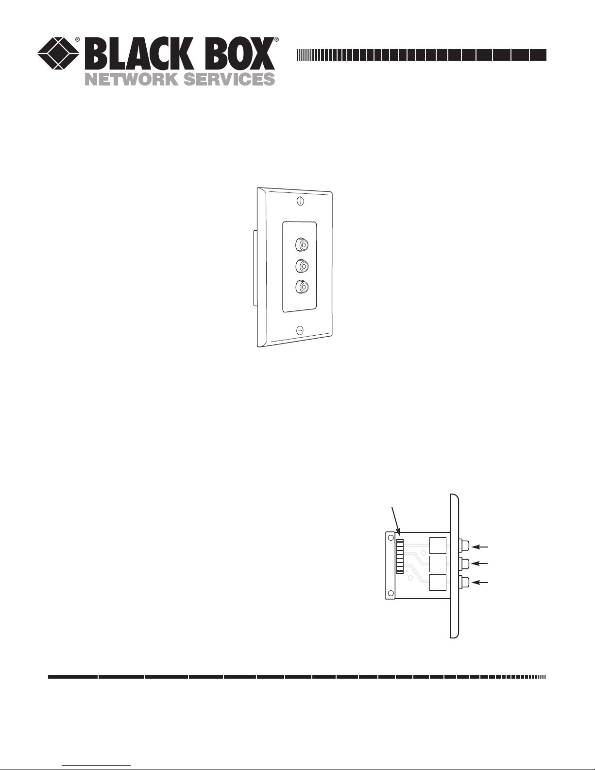
In-wall mounting eliminates external adapters. Figure
2-1 illustrates the module.
Figure 2-1. Component Video UTP Wallmount Module.
110-type
IDC
Green (Y)
Blue (Pb)
Red (Pr)
Pure Home Networking Component
Video (Y-Pb-Pr) UTP Wallmount Module
Page 2

1000 Park Drive • Lawrence, PA 15055-1018 • 724-746-5500 • Fax 724-746-0746
© Copyright 2005. Black Box Corporation. All rights reserved.
Any trademarks mentioned in this manual are acknowledged to be the property of the trademark owners.
3. Installation
3.1 Tools You’ll Need
• UTP termination tool
• Wire cutters
3.2 Cable Handling Guidelines
• Do not route telephone cables through the same
cable holes as the AC power cables.
• For safety, separate all telephone cables from
parallel AC power lines by at least 6 inches
(15.2 cm) whenever possible. Avoid kinking the
cable.
• Do not attach cable tie-downs too tightly. The
cable-fastening hardware should not compress
the cable sheath.
• Do not bend the cable sharply. Place the cables
properly in the cable management after passing
them through the holes, since the edges of the
hole can compress or damage the cable sheath.
• When installing an individual module in the Pure
Home Networking Box, place it above or below
the interfacing module (if possible). This will
eliminate excessive cable crossing.
• For your safety, do not use this or any electrical
product near water (unless it is specifically
designed for wet areas). Do not install wiring
during thunder and lightning storms.
• Use caution when handling or installing any
computer, telephone, video, or electrical devices.
3.3 Attaching a Module to a Wallmount Faceplate
1. Using the appropriate cable stripping tool, strip
approximately 2" (5.1 cm) of the cable jacket.
2. Separate the pairs according to color (whiteblue/blue, white-orange/orange, whitegreen/green, and white-brown/brown).
3. To terminate the connection, place each wire into
the insulation displacement contacts (IDC) by
matching the wire color with the applicable colors
on the punchdown block.
NOTE
We recommend untwisting the pairs no more than 1"
(2.5 cm) from the termination point.
4. If you are using a 110-type punchdown tool,
position the tool over each wire with the cutting
blade facing the outside of the IDC and punch
down firmly.
5. Repeat the process with each pair.
6. Install the included termination caps firmly onto
the IDC.
7. Fasten the insert and wallplate to an electrical box
using the supplied screws.
 Loading...